CAAS-8 eng.cdr - SONTEC Sensorbau GmbH
CAAS-8 eng.cdr - SONTEC Sensorbau GmbH
CAAS-8 eng.cdr - SONTEC Sensorbau GmbH

Create successful ePaper yourself
Turn your PDF publications into a flip-book with our unique Google optimized e-Paper software.
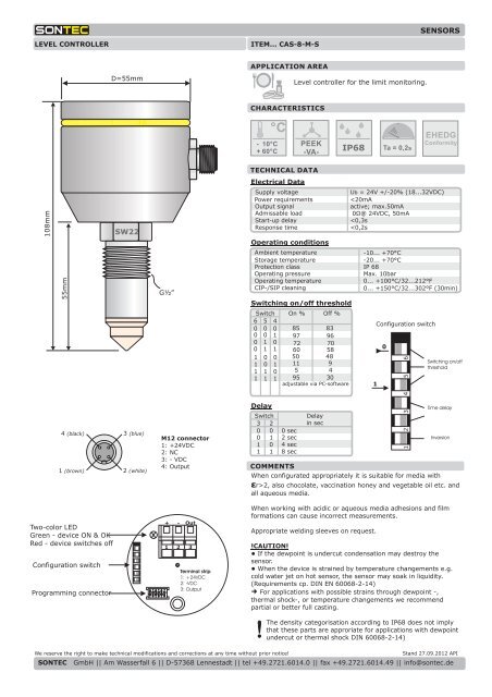
LEVEL CONTROLLER ITEM... CAS-8-M-S<br />
108mm<br />
55mm<br />
D=55mm<br />
SW22<br />
4 (black) 3 (blue)<br />
1 (brown)<br />
Two-color LED<br />
Green - device ON & OK<br />
Red - device switches off<br />
Configuration switch<br />
Programming connector<br />
2 (white)<br />
2 3 4 5 6<br />
1<br />
G½”<br />
M12 connector<br />
1: +24VDC<br />
2: NC<br />
3: - VDC<br />
4: Output<br />
+ - Out<br />
1 2 3<br />
Terminal strip<br />
1: +24VDC<br />
2: -VDC<br />
3: Output<br />
APPLICATION AREA<br />
CHARACTERISTICS<br />
°C<br />
- 10°C<br />
+ 60°C<br />
TECHNICAL DATA<br />
Electrical Data<br />
Level controller for the limit monitoring.<br />
PEEK<br />
-VA-<br />
Supply voltage<br />
Power requirements<br />
Output signal<br />
Admissable load<br />
Start-up delay<br />
Response time<br />
Operating conditions<br />
Ambient temperature<br />
Storage temperature<br />
Protection class<br />
Operating pressure<br />
Operating temperature<br />
CIP-/SIP cleaning<br />
Switching on/off threshold<br />
IP68<br />
Ta = 0,2s<br />
SENSORS<br />
EHEDG<br />
Conformity<br />
U b = 24V +/-20% (18...32VDC)<br />
LEVEL CONTROLLER MANUAL ITEM… CAS-8…<br />
Installation Instructions<br />
!<br />
4 (sw) 3 (bl)<br />
1 (br)<br />
Two-color LED<br />
Green Device ON & OK<br />
Red Device is switching<br />
Configuration switch<br />
Programming connector<br />
Configuration switch<br />
1<br />
0<br />
2 (ws)<br />
2 3 4 5 6<br />
1<br />
2 3 4 5 6<br />
1<br />
M12 plug<br />
1: +24VDC<br />
2: NC<br />
3: - VDC<br />
4: output<br />
1 2 3<br />
Terminal block<br />
1:+24 VDC<br />
2: - VDC<br />
3: output<br />
Switch-on threshold<br />
and switch-off threshold<br />
Delay time<br />
Inversion<br />
SENSOREN<br />
The choice of cable, the installation, protection and electrical connection must be conform to the corresponding special<br />
regulations or country regulations. The electrical connection must only be carried out by qualified personnel.<br />
�The<br />
device shall be protected from electrostatic discharge at the time of installation and operation.<br />
�The<br />
device is not suitable for the installation in explosion-hazard areas.<br />
�The<br />
device must be installed with a designated process adapter sleeve.<br />
�The<br />
connected load circuit must be fused to the maximum output current in order to prevent a defect in the output in<br />
case of a short circuit. Do not connect any additional loads to the terminals for the voltage supply of the device.<br />
�The<br />
two poles of the device shall be disconnected from the mains if live parts can be touched during operation.<br />
�The<br />
supply is not electrically isolated from the sensor ground<br />
�An<br />
incorrect installation and wrongly set parameters can interfere with the operation of the application or even cause<br />
damage. Therefore, independent safety devices should always be available and adjustments must only be carried out by<br />
qualified personnel.<br />
�Do<br />
not direct the spray jet to the electric outlet during external cleaning with a high-pressure cleaner.<br />
The DIN 61000-4-part-5:surge is not accomplished completely due to the product design. Therefore, an additional<br />
protective recommended (e.g. a varistor) or the supply by a protected 24V/DC switched-mode power supply for connecting<br />
Operation<br />
Depending on the sensor type, the electrical connection has to be carried out directly<br />
through the terminal block on the electronics or through the built-in M12 plug. The 24<br />
VDC supply voltage is connected according to the wiring diagram. The active PNP<br />
output must be connected exemplary to a processing control system.<br />
Note: The output voltage is proportional to the input voltage!<br />
Example: At a supply voltage of 20 VDC the output signal has a voltage of < 20 VDC.<br />
Please note that the output can only switch the positive side of the supply voltage<br />
(max. 50 mA). Switching load against ground is not possible!<br />
Settings<br />
The switching action of the sensor can be defined via the configuration switch. It is<br />
possible to adjust the logic, a delay time and the switching threshold. Additionally, the<br />
sensor can be connected to a software whereby the measured values can be<br />
monitored online. Thus, the switching thresholds can be adjusted individually<br />
according to the respective process requirements.<br />
Switch 1<br />
Setting 0: full detector, the output switches by the time the sensor tip is covered by a<br />
medium.<br />
Setting 1: empty detector, the output switches by the time the sensor tip is not<br />
covered by a medium (reverse performance).<br />
Switch 2-3<br />
As stated in the chart “delays”, a switch-on delay and switch-off delay of the output<br />
signal can be set (both times are equivalent respectively). The delay can be used<br />
perfectly whenn the medium does not cover the sensor tip permanently (debouncing).<br />
Example 4 sec: The output reacts only 4 seconds after the cover of the sensor tip is<br />
changed. Thereby, turbulent liquid water surfaces can be repressed.<br />
Switch 4-6<br />
The sensor can be set according to the respective medium via the switch-on and<br />
switch-off thresholds. The percentage measured value is non-dimensional. The switch<br />
setting “4, 5 and 6 = on” enables the parameterization of an user-specific switching<br />
threshold via the software of the PC. A hysteresis can be defined through the switchon<br />
and switch-off thresholds whereby secure switching operations can be achieved,<br />
e.g. in frothing media.<br />
Note: The measured value differs depending on the temperature or production<br />
method of the medium. Thus, the switching thresholds should be provided with<br />
tolerances.<br />
We reserve the right to make technical modifications and corrections at any time without prior notice! Stand 27.09.2012 API<br />
<strong>SONTEC</strong> <strong>GmbH</strong> || Am Wasserfall 6 || D-57368 Lennestadt || tel +49.2721.6014.0 || fax +49.2721.6014.49 || info@sontec.de
Connection<br />
M12 connection<br />
M<br />
Skintop - cable connection Ip68 V<br />
Type<br />
Standard<br />
S<br />
Ingold-Pharma Adaption (please specify details on your order) I<br />
Extended probe tip P<br />
Option<br />
Extended version (only at Standard)<br />
Neck pipe (only at Standard)<br />
e.g. CAS-8 M -S - -<br />
! Caution !<br />
“Extended version”(L) and “neck pipe” (H) cannot be combined in one product.<br />
Order references for sensors of the type CAS-8<br />
L<br />
H<br />
SENSORS<br />
We reserve the right to make technical modifications and corrections at any time without prior notice! Stand 27.09.2012 API<br />
<strong>SONTEC</strong> <strong>GmbH</strong> || Am Wasserfall 6 || D-57368 Lennestadt || tel +49.2721.6014.0 || fax +49.2721.6014.49 || info@sontec.de