Revision 1 to WCAP-14696-A, "Westinghouse Owners Group Core ...
Revision 1 to WCAP-14696-A, "Westinghouse Owners Group Core ...
Revision 1 to WCAP-14696-A, "Westinghouse Owners Group Core ...

You also want an ePaper? Increase the reach of your titles
YUMPU automatically turns print PDFs into web optimized ePapers that Google loves.
<strong>Westinghouse</strong> Non-Proprietary Class 3<br />
<strong>Westinghouse</strong> !<strong>Owners</strong><br />
<strong>Group</strong> <strong>Core</strong> Damage<br />
Assessment Guidance<br />
<strong>Westinghouse</strong><br />
s Electric Company LLC<br />
U ]
oA5004.doclb-112299<br />
WESTINGHOUSE NON-PROPRIETARY CLASS 3<br />
<strong>WCAP</strong>-<strong>14696</strong>-A, <strong>Revision</strong> 1<br />
<strong>Westinghouse</strong> <strong>Owners</strong> <strong>Group</strong><br />
<strong>Core</strong> Damage Assessment Guidance<br />
Robert J. Lutz<br />
July 1996<br />
November 1999 (<strong>Revision</strong> 1)<br />
Work Performed under<br />
Shop Order MUHP-1301 and MUHP-1302<br />
<strong>Westinghouse</strong> Electric Company LLC<br />
SP.O. Box 355<br />
Pittsburgh, PA 15230-055<br />
01999 <strong>Westinghouse</strong> Electric Company LLC<br />
All Rights Reserved
UNITED STATES<br />
j NUCLEAR REGULATORY COMMISSION<br />
D.C. mami<br />
September 2. 1999<br />
/WASMINGTON,<br />
Mr. Lou Uibera<strong>to</strong>rl Chairman<br />
<strong>Westinghouse</strong> <strong>Owners</strong> <strong>Group</strong> Steefn Committee<br />
Indian Point Unht 2<br />
Broadway & Bleakley Ave.<br />
Buhanan, NY 10511<br />
SUBJECT: SAFETY EVALUATION RELATED TO TOPICAL REPORT <strong>WCAP</strong>-14896,<br />
REVISION 1, 'WESTINGHOUSE OWNERS GROUP CORE DAMAGE<br />
ASSESSMENT GUIDANCE' ('AO NO. M97447)<br />
Dear Mr. LUbera<strong>to</strong>rl:<br />
By letter dated November 22, 1996. the <strong>Westinghouse</strong> <strong>Owners</strong> <strong>Group</strong> (WOG) submitted<br />
Topical Report <strong>WCAP</strong>.146, '<strong>Westinghouse</strong> <strong>Owners</strong> <strong>Group</strong> <strong>Core</strong> Dama Assessment<br />
Guidance.' for NRC review. There Is no proprietary version. In ie <strong>to</strong>pical report. a revised<br />
methodology was described tat would be used by licensee emergency response organization<br />
staff for estimating th extent of core damage that may have occurred during an accident at a<br />
<strong>Westinghouse</strong> nuclear power planL The revised methodology Is a revised calculational<br />
technique for estimating core damage which relies on real-time plant Indications rather han<br />
samples of plant fluids.<br />
The revised post-accident core damage assessment methodology In <strong>WCAP</strong>-<strong>14696</strong> replaces<br />
the methodology approved by the staff In 1984. The 1984 methodology was revised for two<br />
major reasons: (1) the current methodology relies on radionucide samples and does not<br />
effectively support emergency response decislonmakin due <strong>to</strong> the significant lime delay in<br />
obtaining and analy'ing thiese samples uing the post-accident Sampling system (PASS). and<br />
(2) the metuidology does not reflect the blest understaeding of fission product behavior.<br />
particularly the sequence-specIfic nature of fisson product retention and hydrogen holdup in the<br />
reac<strong>to</strong>r coolant isteam (RCS), and fission product deposition In I*e containment and sample<br />
ines. Also, as part of a separate request related <strong>to</strong> PASS. ft WOG has requested that the<br />
line commitment for obtaining and analyzing a radionuclide sample be erminated4 thereby<br />
rendering this Information potentially unavailable for use In assessing core damage. The<br />
proposed PASS relaxations, discussed In <strong>WCAP</strong>-14986-P. will be the subject of a separate<br />
staff review and letter.<br />
The NRC staff review of the revised guidance was Initiated In early 1999 following submittal of a<br />
plant-specific application of the guidance by a lead plant, Wolf Creek Generating Station. The<br />
staff met with representatives of the WOG and the licensee on February 24.1999, <strong>to</strong> discuss a<br />
number of comments and questions related <strong>to</strong> the revised guidance. The WOO provided<br />
formal responses <strong>to</strong> these Items Ina letter dated March 16.1999. Based on further review. th<br />
staff Issued a request for additional information (RAI) on March 25 1999. The WOG provided<br />
responses <strong>to</strong> the RAI by letter dated April 28.1999. and a subsequent revision (<strong>Revision</strong> 1) of<br />
the <strong>to</strong>pical report.<br />
The enclosed safety evaluation approves the use of the revised guidance In <strong>WCAP</strong>-<strong>14696</strong>,<br />
<strong>Revision</strong> 1. for core damage assessments for <strong>Westinghouse</strong> nuclear power plants. The staff<br />
RECEI v=:;<br />
S 21 IM<br />
WOG PROJECT OFFICE<br />
November 1999<br />
oAW504doclb-112999 <strong>Revision</strong> 1<br />
iii
L .bera<strong>to</strong>d -.2- September 2, 1999<br />
concludes that the re4sed core damage assessment guideline (CDAG) In Appendci A <strong>to</strong><br />
<strong>WCAP</strong>-1 4696 provides the capability <strong>to</strong> assess the degree of core damage with a sulficlent<br />
level of accuracy and timeliness <strong>to</strong> support emergency response decislonmaklng. The revised<br />
guideline represents an improvement over the existing methodology. It Is both simpler and<br />
more timely, and accounts for fission product and hydrogen retentlon/holdup In the RCS and<br />
fission product removal by containment sprays In an approximate manner. By making core<br />
damage Information available earlier In an event, such that It can be used <strong>to</strong> refine dose<br />
assessments and confirm or extend Initial protective action recommendations, Implementation<br />
of the revised CDAG should Increase the effectiveness of the emergency response<br />
organization. Based on its review, the staff finds the revised CDAG provided in <strong>WCAP</strong>-14690,<br />
<strong>Revision</strong> 1, <strong>to</strong> be an acceptable basis for meeting the NUREG-0737, II..3 requirement for a<br />
core damage assessment procedure.<br />
The NRC requests that the WOO publish an accepted version of the revised <strong>to</strong>pical report<br />
within 3 months of receipt of this letter. The accepted version shall Incorporate this letter and'<br />
the enclosed safety evaluation between the title page and the abstract, and add an -A<br />
(designating accepted) following the report Identification number (Le., <strong>WCAP</strong>-<strong>14696</strong>-A).<br />
If the NRC's criteria or regulations change so that Its conclusion in this letter, that the <strong>to</strong>pical<br />
report is acceptable, Is Invafldated, WOO andfor the applicant referencing the <strong>to</strong>pical report will<br />
be expected <strong>to</strong> revise and resubmit its respective documenta<strong>to</strong>n, or submit Justification for the<br />
continued applicability of the <strong>to</strong>pical report without revision of the respective documentation.<br />
Project No. 694<br />
Enclosure: Safety Evaluation<br />
cc=wenck See next page<br />
Sincerely.<br />
- eohen Dembek. Chief. Section 2<br />
Project Direc<strong>to</strong>rate IV & Decommissioning<br />
Division of Ucensing Project Management<br />
Office of Nuclear Reac<strong>to</strong>r Regulation<br />
iv
OW WLUWITED STATES<br />
NUCLEAR REGULATORY COMMISSION<br />
WASHINGTON. DX.. 8O-.U<br />
SAFETY EVALUATION BY THE OFFICE OF NUCLEAR REACTOR REGULATION<br />
RELATED TO <strong>WCAP</strong>-<strong>14696</strong>. "WESTINGHOUSE OWNERS GROUP CORE DAMAGE<br />
1.0 INTRODuaT!N<br />
ASSESSMENT GUIDANCE: REVISION I<br />
WESTINGHOUSE OWNERS GROUP<br />
By letter dated November 2Z 1996. the <strong>Westinghouse</strong> <strong>Owners</strong> <strong>Group</strong> (WOG) submitted<br />
Topical Report <strong>WCAP</strong>-<strong>14696</strong>, <strong>Westinghouse</strong> <strong>Owners</strong> <strong>Group</strong> <strong>Core</strong> Damage Assessment<br />
Guidance" for NRC review [Reference 1]. This report provides revised guidance for use by<br />
licensee emergency response organization staff In estimating the amount of core damage that<br />
might have occurred duing an accident at a <strong>Westinghouse</strong> nuclear power plant. The<br />
requirement for such guidance was established by the Nuclear redula<strong>to</strong>ry Commission (NRC)<br />
following the Three Mile Island (TMO) 2 accident The rvised guidance Is Intended <strong>to</strong> replace<br />
the post accident core damage assessment methodology (PACDAM) submitted by WOG and<br />
approved by the staff in 1984 (Reference 2].<br />
The WOG proposed a revision of PACDAM for two major reasons. (1) the current methodology<br />
relies on radionuclide samples, and does not effectively support emergency response decision<br />
making due <strong>to</strong> the significant time delay in obtaining and analyzing these samples using the<br />
post-accident sampling system (PASS). and (2) the methodology does not reflect the latest<br />
understanding of fission product behavior, particularly the sequence-specific nature of fission<br />
product retention and hydrogen holdup In the reac<strong>to</strong>r coolant system (RIS), and fission product<br />
deposition In the containment, and sample lines. Also, as part of a separate request related <strong>to</strong><br />
PASS, the WOG has requested that the time commitment for obtaining and analyzing a<br />
radionuclide sample be eliminated, thereby rendering this Information potentially unavailable for<br />
use in assessing core damage. The proposed PASS relaxations, discussed in <strong>WCAP</strong>-14986-P.<br />
are the subject of a separate staff review.<br />
The NRC staff review of the revised PACDAM guidance was initiated In early 1999 following the<br />
submittal of a plant-specific application of the guidance by a lead plant. Wolf Creek Generating<br />
Station. The staff met with representatives of the WOG and the licensee on February 24.1999,<br />
<strong>to</strong> discuss a number of comments and questions related <strong>to</strong> the revised guidance. The WOG<br />
provided formal responses <strong>to</strong> these Items In a letter dated March 16. 1999 [Reference 3].<br />
Based on further review, the staff Issued a request for additional Information (RAI) on March 25.<br />
1999. The WOG provided responses <strong>to</strong> the RAI by letter dated April 28,1999 [Reference 4],<br />
and submitted a subsequent revision of the <strong>to</strong>pical report (<strong>WCAP</strong>-<strong>14696</strong>. <strong>Revision</strong> 1). This<br />
safety evaluation addresses the acceptability of the revised guidance In <strong>WCAP</strong>-<strong>14696</strong>,<br />
<strong>Revision</strong> I (<strong>WCAP</strong>-<strong>14696</strong>) for core damage assessment at a <strong>Westinghouse</strong> nuclear power<br />
plant<br />
ENCLOSURE<br />
November 1999<br />
o:\5004-doclb-112999 <strong>Revision</strong> I<br />
V
2.0 DISUSION<br />
-2<br />
As pat of the TMI Action Plan Requirements (NUREG-0737), NRC required licensees <strong>to</strong><br />
provide a procedure for relating radionuclide concentrations <strong>to</strong> a realistic estimate of core<br />
damage. The primary interest was In being able <strong>to</strong> differentiate between four major fuel<br />
condiltions; no damage, cladding failures, fuel overheating, and core melL The requirement for<br />
a core damage assessment procedure was considered <strong>to</strong> be an element of NUREG-0737<br />
Item n.B.3, Criterion 2 (a). which states:<br />
The licensee shal istabish an onsie radological and chemical anasyls<br />
capab1y <strong>to</strong> provide, within the 3-hour time frame estabrished above. -.<br />
quanta<strong>to</strong>n ofthe foHowOn<br />
(a) Cetain radlonuclldes In the reac<strong>to</strong>r coolant and containment<br />
atmosphere that may be kindca<strong>to</strong>rs of the degree of core damage<br />
(a.g, noble gases, iodkmes and ceslums and non-volatile<br />
iso<strong>to</strong>pes)<br />
The curret WOO Post Accident <strong>Core</strong> Damage Assessment Metiodolog" (PACDAM) was<br />
approved In 1984 based on satisfying this criterion [Reference 53.<br />
The PACDAM relies primarily on radlonuclide analysis <strong>to</strong> establish the extent of core damage.<br />
The core damage estimates derived from radionuclide Information are confirmed using auxiliary<br />
Indica<strong>to</strong>rs, including containment hydrogen concentration, core exit thermocouples (CETs).<br />
reac<strong>to</strong>r vessel level Instrumentation system (RVUS). and containment radiation moni<strong>to</strong>rs.<br />
Because of the significant delays In obtaining and analyzing radionuclide samples, estimates of<br />
core damage based on PACDAM are not generally available <strong>to</strong> support emergency response<br />
decislonmaking, unti about three hours after the decision <strong>to</strong> take these samples.<br />
In <strong>WCAP</strong>-<strong>14696</strong>, the WOO has proposed a revised core damage assessment methodology<br />
that would provide core damage estimates earlier than the present methodology. The report<br />
includes a characterization of how PASS is currently used In <strong>Westinghouse</strong> plants, a detailed<br />
discussion of core damage accident characteristics and the use of Instrument Indications <strong>to</strong><br />
diagnose and evaluate core damage, and a revised methodology for assessing core damage.<br />
The actual "core damage assessment guideline" (CDAG) is provided In Appendix A ofthe<br />
<strong>to</strong>pical report The CDAG setpoints and the background for the guideln are provided In<br />
Appendices B and C, respectively. As part of plant-specific Implementation. licensees would<br />
develop a plant-specifc version of the CDAO based on the information contained In Appendices<br />
A through C.<br />
The COAG relies on fixed plant instrumentation. The extent of core damage is estimated from<br />
containment radiation moni<strong>to</strong>rs and CETe. The core damage estimates are compared <strong>to</strong><br />
indications from hydrogen moni<strong>to</strong>rs, RVUS, hot leg resistance temperature detec<strong>to</strong>rs (RTDs)<br />
and the source range moni<strong>to</strong>r (SRM) <strong>to</strong> confirm that the core status and extent of damage<br />
suggested by the containment radiation moni<strong>to</strong>rs and CET are consistent with these other<br />
indica<strong>to</strong>rs. The CDAG considers fission product and hydrogen retean<strong>to</strong>nfholdup In the RCS.<br />
and the Impact of containment sprays on the arbonme fission product inven<strong>to</strong>ry. The reliance<br />
on radionuclide samples from PASS. which is the primary means of assessing core damage In<br />
vi
-3<br />
PACOAM, Is eliminated In the CDAG. By relying on fixed plant Instrumcftelion and eliminatng<br />
the dependence on PASS, the time required <strong>to</strong> develop a core damage estimate would be<br />
significantly less than with the current methodology (within minutes using the CDAG, versus<br />
about 3 hours using PACDAM/PASS). Earlier availability of core damage Information in an<br />
event would enable licensees <strong>to</strong> use this Information <strong>to</strong> supplement their current emergency<br />
response decaslonmaklng process, thereby Improving the capability <strong>to</strong> protect the public health<br />
and safety. A summary description of the core damage assessment process is provided In the<br />
next section.<br />
8.0 CORE DAMAGE ASSESSMENT PROCESS<br />
In the CDAG provided in Appendix A <strong>to</strong> <strong>WCAP</strong>-<strong>14696</strong>, the status of the core is Itl classffied<br />
based on CET and containment radiation moni<strong>to</strong>r Indications. <strong>to</strong>gether with RCS pressure and<br />
containment spray system status. The status of the core is assigned <strong>to</strong> one of three categories<br />
- no core damage. possible dad damage, possible fuel over-temperature damage. If clad or<br />
fuel over-temperature damage is Indicated, the user is directed <strong>to</strong> corresponding steps (Step A<br />
or Step B of the CDAG, respectively) where more detailed assessments and comparisons am<br />
performed.<br />
If dad damage Is Indicated the percent of core damage Is estimated separately based on<br />
containment radiation and CET irdcations. These estimates are compared with the expected<br />
response from the containment hydrogen moni<strong>to</strong>r, RVUS, hot leg RTD, and source range<br />
moni<strong>to</strong>r, and compared with each other. If the expected response is not obtained (Le.. a<br />
difference in core damage estimates from containment radiation and CETs of less than 60<br />
percent of the estimate using the containment radiation monl<strong>to</strong>r), possible causes for the<br />
deviation are considered.<br />
rf ftJel ave-temperature damage Is suspected, the process Is similar except a more detailed<br />
evaluation of hydrogen concentration Information is performed for over-temperature damage.<br />
The percent of core damage is estimated separately based on containment radiation and CET<br />
Indications. These estimates are compared with the expected response from RVUS, hot leg<br />
RTD, and source range moni<strong>to</strong>r, and compared with each other (wih the expectation Ihat the<br />
difference In core damage estimates from containment radiation and CETs would be less than<br />
60 percent of the estimate using the containment radiation moni<strong>to</strong>r). An estimate of core<br />
damage is also obtained based on lhe containment hydrogen concentration, with consideration<br />
of ROS pressure and vessel reflood. That estimate is not expected <strong>to</strong> deviate from the<br />
estimates developed from the containment radiation and CET indications by more than 25<br />
percent core damage. If the expected response is not obtained, possible causes for the<br />
deviation are considered.<br />
Plant-speelfic curves are used <strong>to</strong> establish the containment radiation level that would be<br />
detected at the containment radiation monl<strong>to</strong>rs as a function of time for 100 percent dad<br />
damage and for 100 percent fuel over-emperature damage. Separate curves are developed<br />
for events with high and low RCS pressure and for events with and without sprays operating. In<br />
developing the plant-specffic curves, adjustments are made <strong>to</strong> account for the effects of fission<br />
product retention In the RCS and fission product removal by spray on the containment radiation<br />
levels. The extent of clad or fuel over-temperature damage Is determined by comparing the<br />
containment radiation moni<strong>to</strong>r reading with the expected value from the corresponding curve.<br />
November 1999<br />
o:\5004doc:b-11299 <strong>Revision</strong> I<br />
vii
.4<br />
In parallel, the extent of dad or fuel over-temperature damage Is determined as the fraction of<br />
CETe that exceed the temperature setpoint value associated with either clad damage or fuel<br />
over-temperature damage. Temperature differentials between CETs and dad are accounted<br />
for in establishing setpoints. in cases where core damage is limited <strong>to</strong> dad damage, a different<br />
CET setpoint value is used <strong>to</strong> denote dad damage depending on whether the RCS is at high or<br />
low pressure.<br />
Auxollaly Indica<strong>to</strong>rs are used <strong>to</strong> confirm the Initial classification of core status, and the extent of<br />
core damage as indicated by CETs and containment radiation moni<strong>to</strong>rs. For core damage that<br />
Is limited <strong>to</strong> clad damage the expected response of the awllay kindica<strong>to</strong>rs Is: no significant<br />
hydrocen detected, reac<strong>to</strong>r vessel water level In a range where only limited clad heatup may<br />
occur, hot leg RTDs less than a value corresponding <strong>to</strong> extensive dad heatup, and source<br />
range moni<strong>to</strong>r count rate corresponding <strong>to</strong> core uncovery. For core damage that Involves fuel<br />
over-temperature damage the expected response of the awdHtWy indica<strong>to</strong>rs is: reac<strong>to</strong>r vessel<br />
water level below an elevation corresponding <strong>to</strong> extensive dad heatup, hot leg RTDs greater<br />
ta a value associated with extensive dad heatup, source range moni<strong>to</strong>r count rate<br />
corresponding <strong>to</strong> core uncovery, and significant hydrogen detected.<br />
4.0 EVALUATION<br />
The scope of the staffs review Included: (1) the rationale for revising the core damage<br />
assessment methodology, and the acceptability of eliminating dependence on PASS. (2) the<br />
appropriateness of control room Indications used <strong>to</strong> assess core damage, (3) the approach for<br />
relating Instrumentation readings <strong>to</strong> core damage estimates, and (4) the consistency of fission<br />
product/hydrogen assumptions and setpolnt values with the current understanding of severe<br />
accident progression and fission product behavior. The staffs assessment Is provided below.<br />
The current core damage assessment methodology does not account for fission product and<br />
hydrogen retentlon/holdup in the RCS, and fission product deposition In the containment, and<br />
sample lines. Information provided In support of the revised guidance indicates that these<br />
mechanisms can be significant In certain sequences. Because they are neither precluded by<br />
PASS design nor accounted for In the current methodology, these mechanisms can bias the<br />
radionuclide and hydrogen concentration samples obtained from PASS, and lead <strong>to</strong> under<br />
estimates of the extent of core damage. The revised methodology includes an explicit, albeit<br />
approximate, accounting of these mechanisms. In addition, by eliminating the current reliance<br />
of the core damage estimate on obtaining and analyzing a radionuclide sample, the timeliness<br />
of the core damage estimate Is substantially Improved. On these bases, the staff considers<br />
modifications <strong>to</strong> the current methodology <strong>to</strong> be warranted.<br />
The CDAG reles on the Indications from the safety-related containment radiation moni<strong>to</strong>rs and<br />
CETs, <strong>to</strong>gether with the RCS pressure and containment spray system status, <strong>to</strong> arrive at an<br />
Initial estimate of core damage. In subsequent steps these indications are further evaluated <strong>to</strong><br />
arrive at an estimate of core damage, and several additional Indica<strong>to</strong>rs are used <strong>to</strong><br />
Independently confirm the core damage estimate, including the safety-retated containment<br />
hydrogen moni<strong>to</strong>r, RVLS, RTDs, and SRM. The staff concludes that the use of fixed plant<br />
instruments in fh manner described In the CDAG provides an acceptable alternative <strong>to</strong><br />
radlochemistry analysis of a radionuclide sample <strong>to</strong> obtain an approximate estimate of the<br />
extent of core damage during the transient phase of an accident The array of Instrument<br />
Vliii
parameters on which the CDAG Is based provide the most direct Indication of the onset and<br />
extent of core damage. These Instrumeants, Include the key indca<strong>to</strong>rs that would be used by<br />
NRC <strong>to</strong> evaluate the extent of core damage during an operattionial event (Responise Technical<br />
Manual. NUREGIBR-0150), as well as several additional indica<strong>to</strong>rs such as RTID and SRM<br />
readings <strong>to</strong> confirm core status. There Is reasonable assurance that these instrumnents.<br />
spedc*fcaly the CEUs. containment radiation moni<strong>to</strong>rs, and hydrogen moni<strong>to</strong>rs, will be available.<br />
since they are Identified as Category I Instruments In Regula<strong>to</strong>ry Gulde 1.97. and as such, are<br />
environmentally qualified, redundant, and powered from batteries In the event of a loss of AC<br />
power'. The process and priorities established In the CDAG for using these Instruments (Le.,<br />
the primary reliance on containment radiation moni<strong>to</strong>rs and CETs. with conflirmation from other<br />
less direct Indica<strong>to</strong>rs) Is commeansurate with the value of the various Instruments In estimnatin<br />
core damage.<br />
The approach for con"Vetn Instrument readings in<strong>to</strong>~core damage estimates Is consistent with<br />
the current understanding of clad and fuel damage characteristics, and accounts for fission<br />
product and hydrogen retentiorv~vdup In an approxdmate fashion. Specifically, containment<br />
radiation moni<strong>to</strong>r readings are compared <strong>to</strong> plant-specific radiation levels for 100 percent clad<br />
damage or fuel over-temperature damage. CET readings are compared <strong>to</strong> values typically<br />
associated with cdad damage and fuel over-temperature damage. and containment hydrogen<br />
coincentration bs compared <strong>to</strong> amount expected In containment for 100 percent over<br />
temperature damage. (CET readings that exceed the selpoints or the operating limits of the<br />
thermocouples are Interpreted as core damage In that region of the core.) The CDAG Includes<br />
a step where the core damage estimates derived separately from different Indica<strong>to</strong>rs<br />
(containment radiation, CET, and containment hydrogen concentration readings) are compared<br />
and reconciled, thereby Irnproving the confidence In the core damage estimate.<br />
The CDAG provides recommended assumptions; regarding fission product release from the fuel<br />
and Msention of fission products within the RCS. These assumptions would be used by<br />
licensees In developing plant-specific curves relating containment radiation readings <strong>to</strong> core<br />
damage. For events limited <strong>to</strong> clad damage (Step A of the guideline). the CDAG assumes the<br />
NUREG-1465 gap release source term Is released <strong>to</strong> the ROS. For events Involvng fuel over<br />
temperature damage (Step B of the guidleline), the WDAG assumes the NUREG-1465 source<br />
term for gap release plus eariy in-essel release Is released <strong>to</strong> the RCS. The in-vessel<br />
releases are adrjusted <strong>to</strong> account for retention of fission products within the RCS. For events<br />
limited <strong>to</strong> clad damage, the COAG assumes 50 percent of noble gases and 2 percent of all<br />
other fission products released lo the ROS are subsequently released <strong>to</strong> the containment In<br />
high pressure sequences, and assumes 100 percent of noble gases and 50 percent of all other<br />
fission products released <strong>to</strong> the 605 are subsequently released <strong>to</strong> containment in low pressure<br />
sequences. For events involvng fuel Over-temperature damage. the WDAG assumes 50<br />
percent of noble gases and 5 percent of all other fission products released <strong>to</strong> the ROS are<br />
subsequently released <strong>to</strong> the containment in high pressure sequences. and assumes no further<br />
reduction In low pressure sequences.<br />
'Thre are about 50 CETs Insa typWca <strong>Westinghouse</strong> reac<strong>to</strong>r, with each thermocouple<br />
representing about 2 percent of She core. There are a minimum of two containment area radiation - high<br />
range moni<strong>to</strong>rs. instflied at widely separated locations. Continuous Indication of contalinmeint hydrogen<br />
concentration Is provided by redundant, sadetyrlated, hydrogen moni<strong>to</strong>rs.<br />
November 1999<br />
o:\5004oclb-112999 <strong>Revision</strong> 1<br />
ix
-6<br />
Additional credit for fission product retention in high pressure sequences is appropriate since<br />
the NUREG-1465 source terms were chosen <strong>to</strong> be representative of sequences with low<br />
pressure In the RCS at the time of core degradation. I-,gh pressure sequences allow for longer<br />
residence time of aerosols released from the core, increased retention of aerosols within the<br />
RCS, and lower releases In<strong>to</strong> containment than provided for In the NUREG.1465 source terms.<br />
A substantial quantity of fission products (as well as hydrogen) is also held-up within the RCS<br />
as compressed vapor. Credit for fission product retention Is reasonable for estimating clad<br />
damage in low pressure sequences since no credit for RCS holdup Is assumed in the NUREG<br />
1465 gap reles source term. In contrast, the NUREO-1465 early In-vessel release source<br />
term accounts for in-vessel fission product retention. Thus, no further reduction I fission<br />
rzwewhxt releases are assumed In the CDAG in estimating fuel over-temperature damage In low<br />
pressure sequences.<br />
The CDAG also assumes al airborne fission products except noble gases ae reduced by a<br />
fac<strong>to</strong>r of 100 for sequences with sprays operating. No reduction of containment fission product<br />
Inven<strong>to</strong>ry Is assumed when sprays are not operating. Existing studies (e.g., OA Simplified Model<br />
of Aerosol Removal by Containment Sprays," NUREG/CR-5966) show that typical pressurized<br />
water reac<strong>to</strong>r containment spray systems are capable of rapidly reducing the concentration of<br />
airborne actvity by about two orders of magnitude within about 30 minutes. Thus, the staff<br />
considers this assumption reasonable.<br />
In response <strong>to</strong> a staff request regarding the bases for the recommended fission product<br />
assumptions, WOO provided results from modular accident analysis program (MAMP)<br />
calculations for several high pressure and low pressure core melt scenarios, with and without<br />
sprays. This information shows the fraction of the fission products predicted <strong>to</strong> reside In the<br />
core, RCS, and containment at various times, including the fraction of fission products that ae<br />
abbome and deposited within the containment The staff considered this Information, as well as<br />
Mhe results from source term code package calculations, the NUREG.1 150 expert ellcitation<br />
process for source term Issues, and more recent MELCOR calculations in Judging the<br />
reasonableness of the hokup/retention assumptions. It should be noted that fission product<br />
releases and distributions vary considerably from sequence <strong>to</strong> sequence, since release and<br />
deposition mechanisms are dependent on sequence specifis, such as core heatup rate,<br />
temperature d1stribnons within the core and RCS, and operation of engineered safety features.<br />
Even for the same sequence, significant differences in predicted fission product behavior are<br />
not uncommon due <strong>to</strong> differences In models and assumptions. Although better unders<strong>to</strong>od<br />
than at the time of the TMI accident, fission product behavior Is complex and the uncertainties<br />
In fission product calculations remain large. As a result, the airborne fission product Inven<strong>to</strong>ry<br />
"seen' by the contalnment radiation moni<strong>to</strong>rs can, realistically, only be related <strong>to</strong> a level of core<br />
damage in an approximate sense. Based on the staff's review, the recommended assumptions<br />
in the <strong>WCAP</strong> provide a reasonable characterization of fission product retention in the RCS for<br />
high and low pressure sequences, within the uncertainties inherent in these parameters. While<br />
the selected values do not bound al1 conceivable scenarios, they would generally lead <strong>to</strong><br />
conservative estimates (Le., over-estimates) of core damage.<br />
The approach taken In the CDAG for translating hydrogen concentration readings In<strong>to</strong> core<br />
damage Involves comparison of the measured containment hydrogen concentration with the<br />
maximum concentration of hydrogen expected for an in-vessel core damage event. The<br />
concentration of hydrogen that is expected in containment Is established for four different<br />
X
categories based on a characterization of results from MAAP calculations. These categories<br />
reflect whether the RCS Is at high or low pressure (which Impacts the quantity of hydrogen<br />
produced as well as retained In the ROS). and whether water has been Injected <strong>to</strong> the core<br />
(which Impacts the quantity of hydrogen produced). The hydrogen selpolnt values are<br />
established for Ice condenser containments as well as large dry containments, with the note<br />
that containment hydrogen concentration would only be a reliable measure of fuel over<br />
temperature for accident sequences In which the hydrogen Igniters were not In operation.<br />
-7<br />
Consideration of water Injection and RCS pressure as distinguishing characteristics Impacting<br />
containment hydrogen concentration Is appropriate since these two fac<strong>to</strong>rs am the slngle-most<br />
Important fac<strong>to</strong>rs Impacting hydrogen production and release. The staff considered the<br />
assumptions recommended In the CDAG for establishing the plant-specfic hydrogen<br />
concentration selpoint values for each of these categories. Silnlar <strong>to</strong> the situation regarding<br />
fission product behavior, hydrogen production and release Is sequence specific. and predicted<br />
hydrogen concentrations can differ slgnificantly from code <strong>to</strong> code. Nevertheless. for purposes<br />
of relating the measured hydrogen concentration <strong>to</strong> an approximate level of core damage. the<br />
assumptions provided In the CWAG provide a reasonable characterization of the extent of<br />
hydrogen produced and retained In the ROS for each of the four categories considered.<br />
As part of the review the staff Identified three areas requiring further ju-tification. These<br />
Include: (1) omission of PASS radionucride samples as a means of confirming core damage<br />
estimates, (2) consistency of clad damage criteria with best estimate burst strain correlations,<br />
and (3) the effect of additional fission product removal mechanisms beyond those considered in<br />
CDAG, specircally, deposition In containment by natural processes. The resolution of these<br />
Issues Is summarized below<br />
The basic question regarding the omission of PASS concerns whether certain elements of the<br />
current methodology should be retalned such that a radionuclide sample could be used <strong>to</strong><br />
confirm the core damage estimate derived from fixed plant instrumentation. The staff<br />
concludes that the methodology can serve Its Intended purpose of classifying the extent of core<br />
damage without relying on PASS. Accordingly, PASS need not be Incorporated as an element<br />
of CDAG.<br />
For purposes of estimating whether clad damage has occurred. the CWAG originally<br />
recommended a CET value of 16000F If ROS pressure exceeds 1600 psig and a CET of<br />
1200"F If RCS pressure Is below 1600 pslg. The staff questioned the consistency of these<br />
temperature/pressure values with best-estimate burt strain correlations. In response. the<br />
WOG provided additional information regarding best-estimate versus conservative calculations.<br />
and results of further evaluations assuming higher bumup fuel. Based on further evaluation.<br />
the WOG reduced the failure criteria (for the high ROS pressure) from 1600"F <strong>to</strong> 1400"F <strong>to</strong><br />
account for lower failure temperatures with higher fuel bumup. The staff concludes that the<br />
revised pressureftemperature setpoint values provide a reasonable measure for assessing the<br />
extent of dad damage.<br />
Fially, the WDAG considers fission product retention In the ROS and removal by containment<br />
sprays, but does not specifically account for fission product deposition i containment by natural<br />
processes. In response <strong>to</strong> a staff request, the WOG provided the results of additional MAAP<br />
calculations showing the fraction of fission products In containment that are airborne and<br />
November 1999<br />
o:\5004.doclb-112999 <strong>Revision</strong> 1<br />
xi
-8<br />
deposited. Based on a review of this Information as well as NRC-sponsored work related <strong>to</strong><br />
aerosol removal (NUREG/CR-61 89). the staff concludes that the impact of natural processes is<br />
within the margin of eor of the CDAG (Le. within the sequence <strong>to</strong> sequence variability in<br />
releases from RCS), and need not be expllclty considered.<br />
In reviewing <strong>WCAP</strong>-14898, the staff also considered the guidance contained In a "Post<br />
Accident Sampling Guide for Preparation of Procedure <strong>to</strong> Estimate <strong>Core</strong> Damage"<br />
[Reference 6]. This document was developed by thO staff and forwarded <strong>to</strong> licensees In the<br />
1982-1983 time-frame. The document (1) discussed fac<strong>to</strong>rs that should be considered In<br />
estimating core damage, and (2) suggested categories of fuel damage. an example of a<br />
wrocess for estimating core damage from radlonucide Informat<strong>to</strong>n, sample locations and their<br />
role, and use of auxilrary Indications <strong>to</strong> confirm core damage estimates derived from<br />
radlonuclide measurements.<br />
The Sampling Guide suggested four broad categories of core damage (no damage, cladding<br />
failure, fuel overheating, and core melt), with the degree of core damage in each category<br />
further delineated. The CDAG enables the degree of core damage <strong>to</strong> be classified In<strong>to</strong> the first<br />
three of these categories, but does not attempt <strong>to</strong> distinguish between extensive fuel<br />
overheating and core meL Recognizing the large uncertainties In accident progression as well<br />
as the role of the core damage assessment methodology In emergency response<br />
dedsaonmaking, such refinement Is not necessary <strong>to</strong> support the decslonmaldng process, and<br />
Implies a greater level of knowledge than Is Justified. As ilustrated by the TU experience. the<br />
extent of core damage and melting was not fully unders<strong>to</strong>od until years after the accident.<br />
Finally. with the shift from reliance on PASS <strong>to</strong> reliance on fixed plant instrumentation, the<br />
specific provisions set forth In the Sampling Guide regarding sampling from the RCS,<br />
containment sump, and containment atmosphere awe no longr relevant <strong>to</strong> the revised<br />
methodology.<br />
5.0 QLCL.USIOH<br />
The staff concludes that the revised CDAG provides the capability <strong>to</strong> assess the degree of core<br />
damage with a sufficient level of accuracy and timeliness <strong>to</strong> support emergency response<br />
decislonmaking at a <strong>Westinghouse</strong> nuclear power plant The revised guideline represents an<br />
Improvement over the existing methodology. It Is both simpler and more timely, and accounts<br />
for fission product and hydrogen retention/holdup In the RCS and fission product removal by<br />
containment sprays In an approximate manner. By making core damage information available<br />
earlier In an event, such that At can be used <strong>to</strong> refine dose assessments and confirm or extend<br />
Initial protective action recommendations, implementation of the revised CDAG should increase<br />
the effectiveness of the emergency response organization. Based on Its review as discussed<br />
above. the staff finds the revised CDAG provided In <strong>WCAP</strong>.14698. <strong>Revision</strong> 1, <strong>to</strong> be an<br />
acceptable basis for meeting the NUREG-0737, 11B.3 requirement for a core damage<br />
assessment procedure.<br />
Principal Conbu<strong>to</strong>n. Ft. Palle<br />
Date: September 2. 1999<br />
xii
o:AS004.doclb-112999<br />
1. <strong>WCAP</strong>-<strong>14696</strong>, <strong>Westinghouse</strong> <strong>Owners</strong> <strong>Group</strong> <strong>Core</strong> Damage Assessment Guidance,<br />
<strong>Westinghouse</strong> Electric Coporation, July 1996.<br />
-9<br />
2. <strong>Westinghouse</strong> <strong>Owners</strong> <strong>Group</strong> letter dated March 23,1984. transmitting <strong>Westinghouse</strong><br />
<strong>Owners</strong> <strong>Group</strong> Post Accident <strong>Core</strong> Damage Assessment Methodology. <strong>Revision</strong> 1,<br />
March 1984.<br />
3. <strong>Westinghouse</strong> <strong>Owners</strong> <strong>Group</strong> letter. OG-99.016. L Ubera<strong>to</strong>rl <strong>to</strong> P. Won. Transmftal of<br />
Responses <strong>to</strong> NRC Comments from the February 24. 1999 <strong>Core</strong> Damage Assessment<br />
Meeting,* March 16, 1999.<br />
4. <strong>Westinghouse</strong> <strong>Owners</strong> <strong>Group</strong> letter. OG-99-040, L Ubera<strong>to</strong>r! <strong>to</strong> Document Control<br />
Desk, "Response <strong>to</strong> NRC Request for Additional Information on <strong>WCAP</strong>-<strong>14696</strong>,"<br />
April, 28, 1999.<br />
5. S. Varga, NRC. <strong>to</strong> J. Sheppard, <strong>Westinghouse</strong> <strong>Owners</strong> <strong>Group</strong>, "Generic <strong>Westinghouse</strong><br />
<strong>Owners</strong> <strong>Group</strong> <strong>Core</strong> Damage Assessment Methodology NUREG-0737, Item ILB.3 Post<br />
Accident System," April 10. 1984.<br />
6. D. Vassallo, NRC, <strong>to</strong> E. Utley, Carolina Power and Ught Company. "Request for<br />
Additional Information, Post Accident Sampling System (NUREG-0737, I.B.$3)," Oc<strong>to</strong>ber<br />
29. 1983.<br />
xiil<br />
November 1999<br />
<strong>Revision</strong> I
TABLE OF CONTENTS<br />
LIST OF TABLE ........................................................................................................................................<br />
LIST OF FIGURES .................................................................................................................................. xvii<br />
EXECUTIVE SUMMARY ................................................................................................................ xxi<br />
1 BACKGROUND ....................................................................................................................... 1-1<br />
1.1 REGULATORY BASIS ................................................................................................ 1-1<br />
1.2 THE EXISTING WOG CORE DAMAGE ASSESSMENT METHODOLOGY ...... 1-2<br />
1.3 RELATIONSHIP OF CORE DAMAGE ASSESSMENT TOEMERGENCY<br />
PLANNING ................................................................................................................... 1-3<br />
2 CHARACTERIZATION OF CORE DAMAGE ACCIDENTS ......... .......... 2-1<br />
2.1 CORE BEHAVIOR DURING AN ACCIDENT ...................................................... 2-1<br />
2.2 FISSION PRODUCT INVENTORIES AND BEHAVIOR ........................................ 2-4<br />
2.2.1 Fission Product Behavior in the <strong>Core</strong> ..................... 2-5<br />
2.2.2 Fission Product Behavior in the RCS and Containment ......................... 2-7<br />
3 DIAGNOSIS OF CORE DAMAGE ..................................................................... .. 3-1<br />
3.1 CORE DAMAGE INDICATORS .......................................................................... . 3-1<br />
3.2 INFORMATION AVAILABILITY AND RELIABILITY ..................... 3-3<br />
4 EVALUATION OF DIAGNOSIS REQUIREMENTS ..................................................... 4-1<br />
5 EVALUATION OF INSTRUMENT INDICATION DURING A CORE<br />
DAM AGE ACCIDENT ............................................................................................................. 5-1<br />
5.1 RESPONSE DURING AN ACCIDENT ..................................................................... 5-1<br />
5.2 SUMMARY - INDICATIONS FOR PREDICTING CORE DAMAGE ................. 5-15<br />
6 METHODOLOGY FOR ASSESSING CORE DAMAGE ............................ 6-1<br />
6.1 INTERPRETATION OF INDICATIONS ................................................................... 6-1<br />
6.2 SUMMARY OF DIAGNOSTIC INDICATIONS ........................... 6-11<br />
6.3 CORE DAMAGE ASSESSMENT GUIDELINE ............................. -12<br />
6.4 PLANT SPECIFIC IMPLEMENTATION OF CORE DAMAGE<br />
ASSESSMENT GUIDANCE .................................. 6-14<br />
7 SUMMARY AND CONCLUSIONS ................................................................................... 7-1<br />
8 REFERENCES ............................<br />
. . .... ........<br />
APPENDIX A CORE DAMAGE ASSESSMENT GUIDELINE<br />
APPENDIX B CORE DAMAGE ASSESSMENT GUIDELINE SETPOINTS<br />
APPENDIX C CORE DAMAGE ASSESSMENT GUIDELINE BACKGROUND<br />
DOCUMENT<br />
APPENDIX D WOG/NRC CORRESPONDENCE<br />
November 1999<br />
o.\5004doc:b-120399 <strong>Revision</strong> 1<br />
xiv
Table 1<br />
Table 2<br />
Table 3<br />
Table 4<br />
Table 5<br />
Table 6<br />
Table 7<br />
o:ASO4.doclb-120199<br />
LIST OF TABLES<br />
Expected <strong>Core</strong> Behavior During an Accident ........................................................... 2-2<br />
Symp<strong>to</strong>ms of <strong>Core</strong> Damage ........................................................................................ 3-2<br />
Comparison of Hydrogen in the RCS and Containment ................................... 5-8<br />
Comparison of Cesium Iodide in the RCS and Containment .............................. 5-10<br />
Potential Candidates for Diagnosing and Assessing <strong>Core</strong> Damage .................... 5-16<br />
Comparison of Source Term Bases ....................................................................... 6-7<br />
Summary of <strong>Core</strong> Damage Indica<strong>to</strong>rs ................. ........... -11<br />
November 1999<br />
<strong>Revision</strong> I<br />
Xv
Figure 1<br />
Figure 2a<br />
Figure 2b<br />
Figure 2c<br />
Figure 2d<br />
Figure 3a<br />
Figure 3b<br />
Figure 3c<br />
Figure 3d<br />
Figure 4<br />
Figure 5<br />
Figure 6<br />
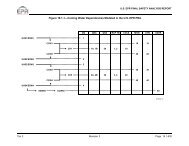
Figure 7<br />
o:\5004.doclb-120199<br />
LIST OF FIGURES<br />
<strong>Core</strong> Exit Thermocouples for a Typical 4 Loop Plant .............................................. 3-4<br />
Fuel Temperature Large LOCA - 1250 Seconds ....................................................... 5-3<br />
Fuel Temperature Large LOCA - 1500 Seconds ....................................................... 5-3<br />
Fuel Temperature Large LOCA - 1750 Seconds .................................................. 5-4<br />
Fuel Temperature Large LOCA - 2000 Seconds ..................................................... 5-4<br />
Fuel Temperature Transient - 11,000 Seconds .......................................................... 5-5<br />
Fuel Temperature Transient - 11,000 Seconds ......................................................... 5-5<br />
Fuel Temperature Transient - 12,000 Seconds ........................................................ 5-6<br />
Fuel Temperature Transient- 13,000 Seconds ......................................................... 5-6<br />
Comparison of <strong>Core</strong> Damage Source Terms ......................... 6-5<br />
Fuel Pellet and Gap Releases High Pressure <strong>Core</strong> Damage Sequence .................. 6-9<br />
Fuel Pellet and Gap Releases Low Pressure <strong>Core</strong> Damage Sequence ................... 6-9<br />
Impact of Decay on Source Terms ............................................................................ 6-10<br />
xvii<br />
November 1999<br />
<strong>Revision</strong> 1
<strong>Westinghouse</strong> <strong>Owners</strong> <strong>Group</strong> Severe Accident Management Guidance<br />
COPYRIGHT 1999 by <strong>Westinghouse</strong> Electric Corporation. All Rights reserved. Printed in the<br />
United States of America. Except as permitted under the Copyright Act of 1976, no part of this<br />
publication may be reproduced or distributed in any form or by any means, without the prior<br />
written permission from <strong>Westinghouse</strong> Electric Company.<br />
These reports bear a <strong>Westinghouse</strong> copyright notice. You as a member of the <strong>Westinghouse</strong><br />
<strong>Owners</strong> group are permitted <strong>to</strong> make the number of copies of the information contained in this<br />
report which are necessary for your internal use in connection with your implementation of the<br />
report results for your plant(s) in your normal conduct of business. Should implementation of<br />
this report involve a third party, you are permitted <strong>to</strong> make the number of copies of the<br />
information contained in this report which are necessary for the third party's use in supporting<br />
your implementation at your plant(s) in your normal conduct of business, recognizing that the<br />
appropriate agreements must be in place <strong>to</strong> protect the proprietary information for the<br />
proprietary version of the report. All copies made by you must include the copyright notice in<br />
all instances if the original was identified as proprietary.<br />
o:5004.doclb-112299<br />
xix<br />
November 1999<br />
<strong>Revision</strong> I
xx<br />
LEGAL NOTICE<br />
This report was prepared by <strong>Westinghouse</strong> as an account of work sponsored by the<br />
<strong>Westinghouse</strong> <strong>Owners</strong> <strong>Group</strong> (WOG). Neither the WOG, any member of the WOG,<br />
<strong>Westinghouse</strong>, nor any person acting on behalf of any of them:<br />
(A) Makes warranty or representation whatsoever, express or implied, (I) with respect <strong>to</strong> the<br />
use of any information, apparatus, method, process, or similar item disclosed in this<br />
report, including merchantability and fitness for a particular purpose, (I) that such does<br />
not infringe on or interfere with privately owned rights, including any party's<br />
intellectual property, or (M) that this report is suitable <strong>to</strong> any particular user's<br />
circumstance; or<br />
(B) Assumes responsibility for any damages or other liability whatsoever (including<br />
consequential damages, even if the WOG or any WOG representative has been advised<br />
of the possibility of such damages) resulting from any selection or use of this report or<br />
any information, apparatus, method, process or similar item disclosed in this report.<br />
WOG <strong>Core</strong> Damage Assessment Guidance<br />
o:\.004.doclb-120199<br />
November 1999<br />
<strong>Revision</strong> I
EXECUTIVE SUMMARY<br />
One of the new regula<strong>to</strong>ry requirements following the Three Mile Island 2 accident was <strong>to</strong><br />
develop and maintain the ability <strong>to</strong> estimate the amount of core damage that might have<br />
occurred during an accident. NUREG-0737, where this requirement is contained, links the<br />
estimation of core damage <strong>to</strong> the declaration of Emergency Action Levels (EALs) which are<br />
linked <strong>to</strong> the implementation of offsite radiological protective actions. To assist utilities in<br />
estimating the amount of core damage, the <strong>Westinghouse</strong> <strong>Owners</strong> <strong>Group</strong> (WOG) funded a<br />
program <strong>to</strong> develop a generic methodology for <strong>Westinghouse</strong> NSSS design plants that, after<br />
NRC review and approval, was used <strong>to</strong> develop the required plant specific capabilities. This<br />
<strong>Core</strong> Damage Assessment Methodology, or CDAM, was based on the knowledge of severe<br />
accidents in the early 1980's and relied heavily on the results of analyses of the radioactive<br />
content of samples of plant fluids.<br />
During the development of the WOG generic Severe Accident Management Guidance (SAMG),<br />
which was completed in 1994, it was noted that the 1984 WOG CDAM did not reflect current<br />
knowledge and understanding of severe accidents. As a result, the WOG authorized a program<br />
<strong>to</strong> revise the 1984 CDAM <strong>to</strong> reflect a current technical basis. During the current program, it was<br />
realized that a simple revision <strong>to</strong> the 1984 methodology was not possible based on substantial<br />
differences in the way that fission products are modeled <strong>to</strong> behavior during a severe accident<br />
over the past 10 years. Thus, the <strong>Core</strong> Damage Assessment Guideline contained in this report is<br />
a <strong>to</strong>tally new approach <strong>to</strong> estimating core damage, compared <strong>to</strong> the previous methodology.<br />
The core damage assessment is intended for use in the Technical Support Center (TSC) or the<br />
Emergency Offsite Facility (EOF) at a nuclear power station. In keeping with the engineering<br />
support philosophy of the emergency response capabilities in the TSC and EOF and recognizing<br />
that substantial variations can occur in the progression of a core damage accident, the new core<br />
damage assessment was developed as GUIDANCE, as opposed <strong>to</strong> a procedure or a cookbook<br />
methodology. This results in a knowledge-based assessment rather than a rigid, rule-based<br />
estimation of core damage.<br />
The core damage assessment guidance contained in this report was developed <strong>to</strong> satisfy the<br />
intent of the new accident prevention, mitigation and assessment regula<strong>to</strong>ry requirements (as<br />
contained in the NRC's NUREG-0737 report) that originated after the Three Mile Island Unit 2<br />
accident. The fundamental need for a method <strong>to</strong> estimate the type and degree of core damage<br />
stems from the need <strong>to</strong> provide timely recommendations with respect <strong>to</strong> offsite radiological<br />
protective measures that should be implemented <strong>to</strong> protect the health and safety of the public.<br />
To satisfy this need, it was recognized that the use of samples of plant fluids would not provide<br />
timely information regarding the condition of the core during the period in the accident<br />
progression where the core condition is changing. Thus, the core damage assessment had <strong>to</strong><br />
rely solely on installed plant instrumentation.<br />
The core damage assessment guidance contained in this report relies on two primary indica<strong>to</strong>rs<br />
for assessing the type and degree of core damage: the core exit thermocouples and the<br />
containment high range radiation moni<strong>to</strong>r. Using these two indications, the user can assess the<br />
condition of the reac<strong>to</strong>r core according <strong>to</strong> three categories that are important for offsite<br />
November 1999<br />
o:\5004.doc:lb-112299 <strong>Revision</strong> 1<br />
xxi
xxii<br />
radiological protection activities: a) no fission product releases from the fuel rods, b) release of<br />
fission product gases from the gap space between the fuel rod cladding and the fuel pellets due<br />
<strong>to</strong> loss of fuel rod cladding integrity, or c) release of significant fission products from the core<br />
due <strong>to</strong> core overheating. Since there can be substantial variations in the conditions that the two<br />
primary indica<strong>to</strong>rs would measure during a core damage accident (primarily due <strong>to</strong> the<br />
possible variations in the progression of a core damage accident), a number of confirma<strong>to</strong>ry<br />
indications are also identified in the core damage assessment guidance. The user is expected <strong>to</strong><br />
use the primary indica<strong>to</strong>rs <strong>to</strong> make a quantitative estimate of the type and degree of core<br />
damage and then use knowledge and judgment <strong>to</strong> determine whether the estimates are<br />
supported by the confirm<strong>to</strong>ry indications.<br />
Since the core damage assessment guidance contained in this report is a generic product that is<br />
applicable <strong>to</strong> all WOG member utility plants, most numerical values in the guidance need <strong>to</strong> be<br />
developed on a plant specific basis. To aid each utility in developing plant specific core damage<br />
assessment guidance, this report also contains a section describing the basis and method for<br />
calculating the plant specific values. Also included in this report is a background document<br />
describing the basis and intent of each of the guideline steps.<br />
The development of plant specific core damage assessment guidance based on the information<br />
contained in this report will result in the capability <strong>to</strong> make an assessment of core damage<br />
based on current knowledge and understanding of core damage accidents and fission product<br />
behavior.<br />
The generic core damage assessment guidance contained in this report has been reviewed and<br />
approved for plant specific application by the Nuclear Regula<strong>to</strong>ry Commission (NRC).<br />
WOG <strong>Core</strong> Damage Assessment Guidance<br />
ox\504.doc2b-i20199<br />
November 1999<br />
<strong>Revision</strong> I
1 BACKGROUND<br />
Why do we need core damage assessment? During and shortly following the accident at Three Mile<br />
Island in 1979, the emergency response team had problems interpreting all of the available<br />
information in terms of predicting the state of the plant and the core in relation <strong>to</strong> both onsite<br />
and offsite emergency response activities. One the "lessons learned" from the Three Mile Island<br />
accident was the need <strong>to</strong> have a method <strong>to</strong> correlate plant information in such a way as <strong>to</strong><br />
provide meaningful recommendations <strong>to</strong> onsite and offsite emergency response functions<br />
(references 1 and 2).<br />
1.1 REGULATORY BASIS<br />
The need for a methodology <strong>to</strong> assess the degree of core damage was part of the US. Nuclear<br />
Regula<strong>to</strong>ry Commission's changes in licensing and operating requirements after the Three Mile<br />
Island accident, as described in NUREG-0737 (reference 3). More specifically, the requirement<br />
for a core damage assessment methodology was issued by the NRC in March 1982 in a<br />
document (reference 4) entitled "Post Accident Sampling Guide for Preparation of a Procedure<br />
<strong>to</strong> Estimate <strong>Core</strong> Damage" which was a supplement <strong>to</strong> NUREG-0737.<br />
The March 1982 NRC requirement in reference 4 required that, in the event of an accident, the<br />
licensee should have some means of realistically differentiating between four major fuel<br />
considerations: no damage, cladding failure, fuel overheating and core melt.<br />
This NRC requirement was closely tied <strong>to</strong> other post TMI-requirements. Specifically, the NRC<br />
post-TMI-2 action plan called for an emergency classification scheme which required the<br />
diagnosis of failure of the fission product boundaries and, in particular, the fuel rod cladding.<br />
The requirement for an emergency classification scheme is contained in 10 CFR 50.47 (b)(4):<br />
"A standard emergency classification and action level scheme, the bases of which include facility<br />
system and effluent parameters, is in use by the nuclear<br />
facility licensee<br />
and 50.47(b)(9):<br />
"Adequate methods, systems, and equipment for assessing and moni<strong>to</strong>ring actual or potential<br />
offsite consequences of a radiological emergency condition are in use."<br />
The emergency classification scheme that was used by most plants in the 198OYs and early 1990's<br />
is based on information in Appendix 1 of NUREG/CR-0654 (reference 5). The emergency<br />
classification scheme detailed in NUREG/CR-0654 depends, in part, on the diagnosis of failures<br />
of the fission product boundaries, including the fuel rod cladding. In the early 1990's the<br />
Nuclear Energy Institute (NEI)Q sponsored the development of an updated emergency<br />
NEI was formerly known as the Nuclear Management and Resources Council, Inc., or NUMARC.<br />
WOG <strong>Core</strong> Damage Assessment Guidance November 1999<br />
o:M,04.doclb-113099 <strong>Revision</strong> I<br />
1-1
1-2<br />
classification scheme (reference 6). This updated emergency classification scheme also relies on<br />
the identification of a loss of the fuel rod cladding integrity as part of the classification criteria.<br />
The NRC requirements for post accident sampling system capabilities are contained in 10 CFR<br />
Part 5034(f)(2)(viii) for plants that did not have a construction permit at the time of the TMI-2<br />
accident However, none of the existing WOG operating plants fall under the requirements of<br />
this section of 10 CFR Part 50.34. For those plants that had a construction permit or operating<br />
license at the time of the TMI-2 accident (all of the existing WOG operating plants), the<br />
applicable post accident sampling criteria are contained in NUREG-0737, Criteria ILB3:<br />
"A design and operational review of the radiological spectrum analysis facilities shall be<br />
performed <strong>to</strong> determine the capability <strong>to</strong> promptly quantify (in less than 2 hours) certain<br />
radionudides that are indica<strong>to</strong>rs of the degree of core damage. Such radionudides are noble gases<br />
(which indicates daddingfailure), iodines and cesiums (which indicate high fuel temperatures),<br />
and nonvolatile iso<strong>to</strong>pes (which indicate fuel melting)-.<br />
Thus, there is no requirement for a core damage assessment methodology in 10 CFR Part 50.<br />
The only regula<strong>to</strong>ry requirements related <strong>to</strong> the ability and methods <strong>to</strong> perform core damage<br />
assessments following an accident are contained in NUREG-0737 and its supplements. On a<br />
plant specific basis, there may also be requirements contained in Technical Specifications<br />
and/or Operating license conditions which will vary on a plant specific basis.<br />
1.2 THE EXISTING WOG CORE DAMAGE ASSESSMENT METHODOLOGY<br />
In 1983 the <strong>Westinghouse</strong> <strong>Owners</strong> <strong>Group</strong> (WOG) initiated a program <strong>to</strong> develop a generic<br />
methodology for assessing core damage for <strong>Westinghouse</strong> PWRs. The WOG <strong>Core</strong> Damage<br />
Assessment Methodology, or CDAM, was released for NRC review and comment in February<br />
1984 and was finalized after two revisions dictated by NRC questions and comments. The final<br />
document is entitled '<strong>Westinghouse</strong> <strong>Owners</strong> <strong>Group</strong> Post Accident <strong>Core</strong> Damage Assessment<br />
Methodology" (reference 7). The WOG <strong>Core</strong> Damage Assessment Methodology was found<br />
acceptable <strong>to</strong> the NRC and a Safety Evaluation Report was issued by the NRC in April of 1984<br />
(reference 25).<br />
The WOG CDAM relied on measurement of fission product concentrations in the reac<strong>to</strong>r<br />
coolant system and containment These measurements were <strong>to</strong> be obtained using the post<br />
accident sampling system, or PASS. It is based on the release of fission products <strong>to</strong> the reac<strong>to</strong>r<br />
coolant system when insufficient cooling is provided <strong>to</strong> the fuel elements. Those fission<br />
products contained in the fuel pellet - fuel cladding interstices were presumed completely<br />
released upon failure of the cladding. Additional fission products were assumed <strong>to</strong> be released<br />
from the fuel pellet during overtemperature and fuel melt conditions. These measurements,<br />
<strong>to</strong>gether with auxiliary readings from the core exit thermocouples, water level in the reac<strong>to</strong>r<br />
vessel, containment radiation moni<strong>to</strong>rs, and hydrogen sampling were then used <strong>to</strong> develop an<br />
estimate of the kind and extent of fuel damage.<br />
The 1984 WOG CDAM was based on the knowledge of the progression of a core damage<br />
accidents and the fission product behavior that was available prior <strong>to</strong> 1984. Thus the WOG<br />
WOG <strong>Core</strong> Damage Assessment Guidance November 1999<br />
o\5004.docAb113099<br />
<strong>Revision</strong> I
CDAM placed nearly equal reliance on the measurement of specific fission products iso<strong>to</strong>pes,<br />
including xenon, kryp<strong>to</strong>n, iodine, cesium, tellurium, strontium, and barium. The methodology<br />
used the auxiliary indica<strong>to</strong>rs as a confirmation that core damage had occurred, but not <strong>to</strong><br />
provide a useful estimate of the degree of core damage. The WOG CDAM also provided a<br />
number of correction fac<strong>to</strong>rs <strong>to</strong> account for non-equilibrium core fission product inven<strong>to</strong>ries.<br />
1.3 RELATIONSHIP OF CORE DAMAGE ASSESSMENT TO EMERGENCY<br />
PLANNING<br />
At the initiation of the 1995 WOG program <strong>to</strong> revise the 1984 <strong>Core</strong> Damage Assessment<br />
Methodology (CDAM), a survey of the WOG utilities was undertaken <strong>to</strong> determine how the<br />
present CDAM was used and what ties existed <strong>to</strong> the utility's Site Emergency Plan (E-Plan) or<br />
other emergency response functions. The following is a generalized summary of the findings<br />
regarding the linking of core damage assessment <strong>to</strong> other emergency planning functions.<br />
Although all utilities have implemented a core damage assessment methodology, these<br />
generalized findings do not represent any particular plant. In the range of responses, some<br />
plants did not routinely exercise the CDAM in emergency drills and exercises while others use<br />
it very rigorously. The generalized summary is meant <strong>to</strong> represent the majority of the WOG<br />
utilities.<br />
The ability <strong>to</strong> globally assess the amount of core damage is generally tied <strong>to</strong> several other<br />
Emergency Planning functions:<br />
1. <strong>Core</strong> damage assessment is used <strong>to</strong> determine ifthefuel barriers are breached in the determination<br />
of the appropriate<br />
emergency action levels.<br />
Reference 5 suggests that an Unusual Event should be based on "failed fuel moni<strong>to</strong>r<br />
(PWR) indicates increase greater than 0.1% equivalent fuel failures within 30 minutes".<br />
Further, reference 5 suggests an Alert condition based on "failed fuel moni<strong>to</strong>r (PWR)<br />
indicates increase greater than 1% fuel failures within 30 minutes or 5% <strong>to</strong>tal fuel<br />
failures" or "a very high coolant activity sample (e.g., 300 t.i/cc equivalent of 1-131)".<br />
Reference 5 suggests a Site Emergency based on "degraded core with possible loss of<br />
coolable geometry (indica<strong>to</strong>rs should include instrumentation <strong>to</strong> detect inadequate core<br />
cooling, coolant activity and/or containment radioactivity levels)". However, no specific<br />
values are suggested in reference 5 for the Site Emergency criteria.<br />
Reference 6 suggests an emergency classification scheme that is based on loss (or<br />
potential loss) of fission product barriers, namely the fuel rod cladding, the reac<strong>to</strong>r<br />
coolant pressure boundary and containment fission product boundary. Reference 6<br />
suggests that a loss of fuel clad barrier should be based on one or more of the following<br />
indications: a) primary coolant activity level greater than 300 pCi/cc 1-131 equivalent, or<br />
b) core exit thermocouple readings in excess of 1200 0 F. In addition, reference 6 suggests<br />
that a loss of both RCS and fuel clad barrier should be based on a containment radiation<br />
moni<strong>to</strong>r reading which indicates escape of noble gases and iodine <strong>to</strong> containment that is<br />
equivalent <strong>to</strong> 300 pCi/cc 1-131 equivalent. Reference 6 suggest that the 300 pCi/cc 1-131<br />
equivalent is well above that expected for iodine spikes and corresponds <strong>to</strong> about 2 <strong>to</strong><br />
WOG <strong>Core</strong> Damage Assessment Guidance November 1999<br />
o:\Soo4doclb-113o99<br />
<strong>Revision</strong> 1<br />
1-3
14<br />
5% fuel clad damage. In addition, reference 6 suggests that a containment radiation<br />
level equivalent <strong>to</strong> 20%/6 fuel rod clad damage should be used <strong>to</strong> provide indication of<br />
potential loss of containment barrier.<br />
2. <strong>Core</strong> damage assessment is used <strong>to</strong> select the source term for use in the offsite dose assessment<br />
function whih, in turn, supports the utility recommendations for offsite protective actions.<br />
A number of utilities use the core damage assessment <strong>to</strong> determine the source term that<br />
should be used in the offsite dose projection methodology. The offsite dose projection is<br />
used <strong>to</strong> make realistic offsite emergency protective action recommendations <strong>to</strong> the<br />
appropriate governmental agencies as identified in the utility Site Emergency Plan. In<br />
determining the proper source term <strong>to</strong> use in the offsite dose projection, the containment<br />
inven<strong>to</strong>ry of the various radionuclides in the offsite dose projection are determined from<br />
the amount of clad damage, core overtemperature fission product release and core<br />
melting. Each utility uses the core damage assessment input differently. At one end of<br />
the spectrum, the input <strong>to</strong> the offsite dose projection can be a continuum of core damage<br />
conditions ranging from fuel cladding gap release <strong>to</strong> melting of the entire core and<br />
subsequent failure of the reac<strong>to</strong>r pressure vessel. At the other end of the spectrum, the<br />
offsite dose projection input from the core damage assessment is limited <strong>to</strong> determining<br />
whether clad damage and/or core melting has occurred.<br />
3. <strong>Core</strong> damage assessment is used <strong>to</strong> predict the radiation protection actions that should be<br />
consideredJor long term recovery activities.<br />
Many utilities use the core damage assessment <strong>to</strong> provide input <strong>to</strong> the onsite operations<br />
support activities, although no formal procedures are developed at many of the plant<br />
sites. There are several specific issues where input from the core damage assessment<br />
provides information for operational support decision making.<br />
The <strong>Westinghouse</strong> <strong>Owners</strong> <strong>Group</strong> Emergency Response Guidelines (reference 10)<br />
provides "cautions" and "notes" in a number of the individual procedures related <strong>to</strong><br />
potential radiation levels in specific plant areas if the reac<strong>to</strong>r coolant system isolation is<br />
defeated following an SI signal. For example, at the point where the guidelines<br />
recommend that reac<strong>to</strong>r coolant system letdown be re-established (as at ES-1.1 SI<br />
Termination, step 13 of the HP Version) following the attainment of a safe, stable core<br />
configuration after an SI signal, the procedure cautions that potentially dangerous<br />
radiation levels could exist at some in-plant locations if core damage had occurred. The<br />
same type of caution is noted when long term heat removal using the residual heat<br />
removal system is established following an SI signal (as at step 1 of ES-1.3 Transfer <strong>to</strong><br />
Cold Leg Recirculation). While the generic WOG ERGs refer <strong>to</strong> high reac<strong>to</strong>r coolant<br />
activity levels, many utilities use the core damage assessment <strong>to</strong> satisfy assess these<br />
cautions.<br />
The core damage assessment can also provide input <strong>to</strong> the radiation protection activities<br />
during an accident. By knowing the degree of core damage, the amount of radiation<br />
protection and radiation survey information that should be anticipated can be<br />
WOG <strong>Core</strong> Damage Assessment Guidance<br />
o:\500Mdoclb-123099<br />
November 1999<br />
<strong>Revision</strong> I
determined. For example, if only fuel rod cladding damage is suspected, the radiation<br />
levels in various plant areas can be estimated and the appropriate radiation surveys and<br />
radiation protection for workers can be forecast before the actual radiation surveys are<br />
initiated. This can save radiation exposure <strong>to</strong> the plant health physics staff.<br />
Lastly, when fully implemented by December of 1998, the <strong>Westinghouse</strong> Severe<br />
Accident Management Guidance (WOG SAMG) (reference 11) suggests that an<br />
assessment of the radiation levels in various plant areas can provide input <strong>to</strong> decisions<br />
regarding the recovery and repair of unavailable equipment that could be used <strong>to</strong><br />
manage a core damage accidente. As a minimum, some of cladding damage will have<br />
occurred prior <strong>to</strong> entry in<strong>to</strong> the WOG SAMG from the ERGs. The core damage<br />
assessment can be useful in providing information regarding the degree of core damage<br />
and the resultant radiation levels in various plant areas.<br />
4. <strong>Core</strong> damage assessment is used <strong>to</strong> satisfy inquiries from local and federal government<br />
agencies and provides supportive evidence that the utility knows the plant conditions.<br />
Once a plant emergency is declared and offsite authorities are notified, one of the<br />
questions that will be asked is the status of the core. The utility's ability <strong>to</strong> quickly and<br />
accurately respond <strong>to</strong> these information requests will enable the appropriate offsite<br />
radiation protection actions <strong>to</strong> be carried out efficiently and effectively. The bot<strong>to</strong>m line<br />
is that if the utility emergency response organization can provide a confident estimate of<br />
the status of the core, the appropriate offsite emergency protective actions are likely <strong>to</strong><br />
be implemented rather than extreme measures based on lack of confidence in the utility<br />
assessment.<br />
For example, the NRC's RTM-96 (reference 12) specifies that the NRC emergency<br />
response activities should be based on the degree of core damage. RTM-96 contains a<br />
methodology for estimating the status of the core from plant instrumentation readings<br />
and analysis of samples of plant fluids provided by the utility. However, the<br />
methodology in RTM-96 is very general. The refinement of the core damage estimation<br />
based on utility input can be valuable in assessing whether the offsite emergency<br />
protective actions recommended based on the RTM-96 estimates are appropriate.<br />
2 A severe accident, as defined in the WOG SAMG, is one where the core exit thermocouple indications ae greater<br />
than 12008F and no actions can be taken <strong>to</strong> mitigate dhe core overheating event. Sometimes "seve accident" and<br />
"core damage accident" are used interchangeably. However, core damage accidents include hose events which<br />
approach severe accident status but are mitgatcd before oeaching the severe accident stage.<br />
WOG <strong>Core</strong> Damage Assessment Guidance November 1999<br />
o:\04.docIb-l13099 <strong>Revision</strong> I<br />
1-5
2 CHARACTERIZATION OF CORE DAMAGE ACCIDENTS<br />
This section presents a summary of the current understanding of core damage accidents as it<br />
relates <strong>to</strong> the assessment of core damage. The overall core behavior during a core damage<br />
accident is briefly discussed, followed by a summary of the fission product release from the core<br />
and then the fission product behavior after release from the fuel matrix. It is very important <strong>to</strong><br />
establish the basis for the progression of a core damage accident and the behavior of the core<br />
and fission products before attempting <strong>to</strong> formulate the characteristics of core damage in terms<br />
of measurable parameters. The following information represents the current knowledge and<br />
understanding of core and fission product behavior during a core damage accident.<br />
2.1 CORE BEHAVIOR DURING AN ACCIDENT<br />
The fuel rods in a <strong>Westinghouse</strong> PWR are constructed of a zirconium tube (called fuel rod<br />
cladding) with caps on each end. The fuel rods contain uranium dioxide fuel pellets. The gas<br />
space inside the fuel rod cladding is initially pressurized with helium and during normal<br />
operation, the internal pressure of the fuel rod increases as a result of the heat generated by the<br />
fissioning of the uranium and the migration of some of the fission products, primarily xenon <strong>to</strong><br />
the gap space. Thus during normal operation, there is a slight negative pressure inside the fuel<br />
rod with respect <strong>to</strong> the reac<strong>to</strong>r coolant system. The fuel rod cladding serves two primary<br />
purposes: a) <strong>to</strong> keep the fuel pellets in a geometry that assures a controlled and efficient fission<br />
process, and b) <strong>to</strong> contain radioactive fission products, thereby preventing their release in<strong>to</strong><br />
plant systems or the atmosphere.<br />
There are four types of core damage that can occur during an accident in a <strong>Westinghouse</strong> PWR:!<br />
1. Loss of fuel rod integrity without the loss of the water coolant surrounding the fuel rod,<br />
2. Loss of fuel rod integrity without chemical reactions of the zirconium fuel rod cladding,<br />
3. Loss of fuel rod integrity without melting of the fuel rod cladding and/or fuel pellets,<br />
and<br />
4. Loss of fuel rod integrity accompanied by fuel melting.<br />
The second through fourth damage types are similar <strong>to</strong> the core damage classifications<br />
described in NUREG-0737 (reference 4): a) fuel rod cladding failure, b) fuel pellet overheating,<br />
and c) core melting. However, for the purposes of the following discussions, the four types of<br />
core damage listed above will be used since it better describes the core damage accident<br />
progression and the physical and chemical processes that occur as core damage progresses.<br />
The overall expected core behavior during an accident is dictated by the fuel rod cladding<br />
temperature and fuel pellet temperatures in individual fuel rods in the core. A summary of the<br />
behavior, taken from reference 13, is provided in Table 1. This information is consistent with<br />
WOG <strong>Core</strong> Damage Assessment Guidance November 1999<br />
o=504.doclb-11399 <strong>Revision</strong> 1<br />
2-1
2-2<br />
the core behavior modeled by best estimate accident codes such as MAAP 3.OB and MAAP 4.0<br />
(references 14 and 15 respectively).<br />
With these temperatures in mind, the four basic types of fuel damage can now be discussed.<br />
The first type of core damage is the failure of the fuel rod cladding due <strong>to</strong> rapid temperature<br />
and pressure transients in the fuel pellets. In this type of event, the reac<strong>to</strong>r coolant still<br />
surrounds the outside of the fuel rod cladding, but heat transfer <strong>to</strong> the water cannot prevent<br />
heating of the fuel pellets and cladding. For example, in the event of a rapid power excursion as<br />
a result of an accident (e.g., rod ejection accident) the energy buildup inside the fuel pellets can<br />
result in the localized failure of the fuel rod cladding due <strong>to</strong> mechanical (swelling of the fuel<br />
pellet) and thermal stresses (localized heating of the fuel rod gas and cladding). Due <strong>to</strong> the<br />
control rod design in a <strong>Westinghouse</strong> PWR, this type of core damage is generally localized in<br />
nature affecting less than 1% fuel rods 3 .<br />
Table I Expected <strong>Core</strong> Behavior During an Accident<br />
<strong>Core</strong> Temperature <strong>Core</strong> Behavior<br />
5400(F<br />
4800OF<br />
4200 0 F<br />
36000 F<br />
30000P<br />
2400 0 F<br />
1800 0 F<br />
1200OF<br />
Melting of fuel pellets<br />
While the FSAR analyses show that as much as 10% of the rods may undergo DNB for rod ejection and rod<br />
witdrwal accidents using €onservaive assumptions, the acumal damage is expected <strong>to</strong> be limited <strong>to</strong> less ta 1% of<br />
the fud rods.<br />
WOG <strong>Core</strong> Damage Assessment Guidance<br />
o:\5OUdoc:Ib-113099<br />
a<br />
Release of all volatile fission products from fuel<br />
Possible formation of uncoolable core<br />
Fuel pellets dissolve in melt components<br />
Very rapid release of volatile fission products from fuel pellets<br />
Very rapid Zirc water reaction; formation of hydrogen and failure of<br />
fuel rod cladding<br />
Possible fuel cladding burst - release of fission products in gap space<br />
Little possibility of fuel cladding rupture<br />
November 1999<br />
<strong>Revision</strong> I
The second core damage type is damage <strong>to</strong> the integrity of the fuel rod cladding that occurs as a<br />
result of a combination of thermal and mechanical stresses acting on the fuel rod due <strong>to</strong> the loss<br />
of coolant surrounding the fuel rod cladding for a limited time period. A number of analyses<br />
(reference 17, for example) are available <strong>to</strong> show that high core temperatures normally<br />
associated with core damage (e.g., greater than 1800 *F) are not required <strong>to</strong> cause failure of the<br />
fuel rod cladding in some of the fuel rods in the core. A small LOCA or a large LOCA, where<br />
the emergency core cooling system operates as designed, can result in temperatures in the core<br />
which are only above the normal operating temperatures for a short period of time. This results<br />
in the heatup of the fuel pellets as heat removal is severely limited when the upper portion of<br />
the fuel rods are uncovered, followed by a cooldown as the cold safety injection water recovers<br />
the fuel rods. However, the combination of these temperatures, which also results in an<br />
increased pressure differential across the fuel rod claddin& and mechanical stresses in the fuel<br />
rod, due for example <strong>to</strong> cold water injection, can result in localized failures of the fuel rod<br />
cladding. This type of fuel rod failure can be widespread throughout the core, depending on<br />
actual conditions.<br />
The third type of core damage is the loss of fuel rod integrity accompanied by sustained high<br />
fuel rod cladding and pellet temperatures resulting in the oxidation of a significant fraction of<br />
the fuel rod cladding. In this type of event, the decay heat in the fuel pellets cannot be<br />
effectively removed due <strong>to</strong> the lack of coolant on the outer surface of the fuel rods. As a result,<br />
the fuel pellet and fuel rod cladding continues <strong>to</strong> heatup until the temperature of the fuel rod<br />
cladding is great enough that the zirconium cladding begins <strong>to</strong> react with the steam<br />
surrounding the outer surface of the fuel rod cladding. It is worthwhile <strong>to</strong> note that this<br />
behavior begins <strong>to</strong>ward the <strong>to</strong>p of the core and near the highest power region prior <strong>to</strong> the<br />
accident. The reaction of the zirconium cladding and the steam in the reac<strong>to</strong>r coolant system is<br />
exothermic (the reaction produces additional heat) and produces hydrogen. The reaction,<br />
whose rate is a function of the zirc temperature, which can be described by:<br />
Zr+I1O -+ ZrO+-1+heat<br />
Analyses with thermal hydraulic computer codes have shown that the heat addition from the<br />
zirc - steam reaction can be many times the decay heat over the time of significant zirc reactions.<br />
Since most of the heat of reaction is retained in the zirc oxide, this chemical reaction accelerates<br />
the fuel pellet heatup rate and melting temperatures can be approached in tens of minutes<br />
(reference 17).<br />
The fourth and final type of core damage is one in which the original core geometry is<br />
drastically changed as a result of melting and downward relocation of the core and cladding<br />
materials. This begins <strong>to</strong> occur when the fuel pellet and cladding temperatures approach about<br />
4000TF. At this temperature, a eutectic' is formed between the uranium oxide fuel pellets and<br />
the zirc cladding. This eutectic has a melting temperature slightly greater than 4000 0 F, which is<br />
4 A anectic is a chemical solution or alloy that has a lower melting point than any of its const.uent pmu.<br />
WOG <strong>Core</strong> Damage Assessment Guidance November 1999<br />
o:5004.doclb-113099 <strong>Revision</strong> 1<br />
2-3
2-4<br />
significantly lower than the melting temperature of either UCz, Zr or ZrO. Once formed, the<br />
molten eutectic begins <strong>to</strong> relocate downward in the core where is may resolidify on cooler<br />
surfaces.<br />
Based on the fission product behavior in the fuel, there are two distinct phases <strong>to</strong> the fuel<br />
melting phase of core damage: in-vessel core melting and ex-vessel core melting.<br />
As core melting progresses and core material continues <strong>to</strong> relocate <strong>to</strong> lower levels of the reac<strong>to</strong>r<br />
vessel, all of the gaseous and volatile fission products will be released from the fuel. However,<br />
the tellurium (which is a volatile fission product) will chemically combine with urreacted<br />
zirconium and will not be released as long the core material remains inside the reac<strong>to</strong>r vessel.<br />
For the non-volatile fission products there is no physical or chemical process that would cause<br />
their release from the molten fuel mass as long as the core material remains inside the reac<strong>to</strong>r<br />
vessel.<br />
If cooling cannot be established in the core region prior <strong>to</strong> the time that molten core material<br />
begins <strong>to</strong> drain in<strong>to</strong> the lower hemispherical head of the reac<strong>to</strong>r vessel, the molten core material<br />
will begin <strong>to</strong> accumulate in the reac<strong>to</strong>r vessel lower head. Heat transfer between the molten<br />
core material and the steel wall of the lower head will result in heat up of the lower head. If this<br />
heatup is not mitigated, failure of the lower head will eventually occur and permit the molten<br />
core material <strong>to</strong> enter the reac<strong>to</strong>r cavity region of the containment. At this time, there are<br />
several phenomena that can result in the release of the tellurium and a small portion of the non<br />
volatile fission products from the molten core mass. The phenomena responsible for this<br />
additional release includes core-concrete interactions, steam explosions', and debris transport<br />
out of the cavity region.<br />
2.2 FISSION PRODUCT INVENTORIES AND BEHAVIOR<br />
Before getting in<strong>to</strong> the diagnosis of core damage, we need <strong>to</strong> establish some basic information<br />
regarding fission product inven<strong>to</strong>ries and behavior.<br />
Radioactive fission products can be divided in<strong>to</strong> 6 broad groups, based on their chemical<br />
properties and their potential for health effects (reference 8):<br />
* .Noble gas - These radioactive species exist as a pure gas at all accident conditions and<br />
do not react with other materials <strong>to</strong> form new compounds.<br />
* -Iodine - These radioactive species exist as cesium iodide in the fuel matrix. Cesium<br />
iodide is a volatile substance with a melting point of about 1150*F and is quite volatile at<br />
temperatures over 2000F. A small amount of the cesium iodide can also react with<br />
Steam explosion, as used hem refers <strong>to</strong> the nondestructive steam explosions that can occur and result in<br />
fragwmntaon and transport of core debris and associated fission products. The large destructive steam explosions<br />
once thought <strong>to</strong> contribute <strong>to</strong> contaihinmet ure have been shown <strong>to</strong> be physically impossible <strong>to</strong> achieve (ref. ITn)<br />
WOG <strong>Core</strong> Damage Assessment Guidance<br />
oc\5004.doclb-l13099<br />
November 1999<br />
<strong>Revision</strong> I
organic substances <strong>to</strong> form various organic iodide comp6unds which can be extremely<br />
volatile under accident conditions.<br />
*-Cesium - These radioactive species exist as cesium iodide and cesium uranate in the fuel<br />
matrix. Under oxidizing conditions, the cesium uranate would become cesium<br />
hydroxide. Both of these are volatile species under accident conditions with cesium<br />
hydroxide having a melting point of about 525 0 F.<br />
-Tellurium - These radioactive species may exist as a solid in the fuel matrix or as cesium<br />
telluride. In either case, tellurium combines with metallic zirconium at accident<br />
temperatures. As the zirconium is oxidized the tellurium is libezated and it <strong>to</strong>o oxidizes<br />
<strong>to</strong> form a tellurium oxide. Tellurium oxide has a low volatility under most accident<br />
conditions.<br />
-Strontium - These radioactive species exist as a solid in the fuel matrix and are known <strong>to</strong><br />
be volatilized under accident conditions. They readily oxidized <strong>to</strong> form strontium oxide<br />
which has a low volatility under accident conditions.<br />
* .Ruthenium - These radioactive species exist as a solid in the fuel matrix and have a<br />
very low volatility under accident conditions. The very small amount that might be<br />
volatilized under accident conditions will oxidized in the steam environment and the<br />
resultant oxide is would likely exist only as an aerosol 6 .<br />
2.2.1 Fission Product Behavior in the <strong>Core</strong><br />
The gaseous and volatile radioactive species exist primarily within the solid ceramic fuel pellets<br />
during normal operation. However, a small fraction of these species exist in the gap space<br />
between the fuel pellets and the fuel rod cladding as a result of migration of these volatile<br />
fission products out of the fuel pellet matrix. On the other hand, almost 100% of the non<br />
volatile species are retained within the ceramic fuel pellet matrix during normal operation.<br />
During normal operation, a small amount of the volatile fission products in the fuel rod gap<br />
space can be released <strong>to</strong> the reac<strong>to</strong>r coolant system if a small defect in the fuel rod cladding<br />
occurs. It has also been observed that if there are one or more fuel rods in the core with defects,<br />
a significant change in the reac<strong>to</strong>r coolant iodine and cesium fission product concentrations<br />
occurs anytime the reac<strong>to</strong>r is tripped or the reac<strong>to</strong>r coolant system is depressurized<br />
(reference 9). While this latter phenomena is termed iodine spiking, the reac<strong>to</strong>r coolant system<br />
noble gas and cesium concentrations also increase upon depressurization of the reac<strong>to</strong>r coolant<br />
system.<br />
An aerosol is a micron sized solid particle of a chenical compound and is equivalent <strong>to</strong> the older ission product tem<br />
"particulate".<br />
WOG <strong>Core</strong> Damage Assessment Guidance November 1999<br />
o:50044ocIb-1l3099 <strong>Revision</strong> 1<br />
2-5
2-6<br />
The current understanding of fission product behavior during an accident is not significantly<br />
different than that given in reference 8. NUREG-1465 (reference 24) provides the most recent<br />
regula<strong>to</strong>ry understanding of fission product behavior in the core and, <strong>to</strong>gether with reference 8,<br />
provides the basis for the discussion below.<br />
During an accident, if a failure of the fuel rod cladding on one or more fuel rods occurs, the<br />
gaseous and some of the volatile fission products in the fuel rod gap space will be released<br />
(termed gap release) <strong>to</strong> the reac<strong>to</strong>r coolant system. In addition, some gaseous and volatile<br />
fission products that reside in the fuel pellet near the outer periphery will also be released with<br />
or shortly after the fission products in the cladding gap space (called embedded gas release).<br />
The overall release has been termed burst release. For noble gases, the burst release can be<br />
between 1% and 25% of the <strong>to</strong>tal rod inven<strong>to</strong>ry of noble gases. Cladding failure would result in<br />
0.04 <strong>to</strong> 5 % of the rod iodine inven<strong>to</strong>ry and 0.02 <strong>to</strong> 5% of the rod cesium inven<strong>to</strong>ry being<br />
released <strong>to</strong> the reac<strong>to</strong>r coolant system as a burst release. The iodine and cesium release<br />
quantities are highly dependent on the pre-accident operating characteristics of the rods and the<br />
temperatures experienced just prior <strong>to</strong> rod burst. The other fission products discussed above<br />
would not be expected <strong>to</strong> be released <strong>to</strong> the reac<strong>to</strong>r coolant system in significant quantities for<br />
fuel rod cladding failures. With respect <strong>to</strong> the burst release of noble gases, iodines and<br />
cesiums, NUREG-1465 recognizes an immediate burst release of 3% of the rod inven<strong>to</strong>ry that is<br />
assumed <strong>to</strong> occur occurs at the time of fuel rod failure and an additional long term release of 2 %<br />
of the rod inven<strong>to</strong>ry over the next 30 minutes.<br />
Further, if the fuel pellets begin <strong>to</strong> overheat during an accident, additional gaseous and volatile<br />
fission products may be released from the fuel pellet matrix, through the ruptured fuel rod<br />
cladding and in<strong>to</strong> the reac<strong>to</strong>r coolant system. This phenomena is termed diffusional release.<br />
When the fuel pellet temperature exceeds approximately 2465 0 F, the noble gases, iodines and<br />
cesiums accumulated at the grain boundaries of the fuel pellets will begin <strong>to</strong> be released. For<br />
fuel rods operating at low power levels during the pre-accident period of operation, fuel rod<br />
temperatures as high as 3250 0 F might be required <strong>to</strong> effect the grain boundary release. As much<br />
as 100% of the rod inven<strong>to</strong>ry of noble gases, iodines and cesiums may be released via this<br />
mechanism.<br />
At the completion of the burst, diffusional and grain boundary releases, very little of the rod<br />
inven<strong>to</strong>ry of noble gases, iodines and cesiums may still remain in the fuel pellet grains. Release<br />
from the grains is insignificant at clad burst temperatures (e.g., 1400 <strong>to</strong> 2000T), but the release<br />
rate is a strong function of temperature. At about 3650 0 F, the release rate can be as high as 10%<br />
of the remaining inven<strong>to</strong>ry per minute. At this rate, the release of noble gases, iodines and<br />
cesiums from the fuel pellets is nearly 100% complete by the time the fuel reaches its melting<br />
temperature of 4000°F. The low volatility fission products would not be released in significant<br />
quantities from the fuel grains <strong>to</strong> the reac<strong>to</strong>r coolant system, even after fuel melting has been<br />
initiated, due <strong>to</strong> their low volatility.<br />
From the perspective of potential offsite releases of fission products and the need <strong>to</strong> recommend<br />
offsite protective actions, there are only three levels of core damage that are important: no<br />
damage, fuel rod cladding damage and fuel overtemperature damage. The majority of the<br />
noble gas and volatile fission products are already released from the fuel prior <strong>to</strong> the onset of<br />
WOG <strong>Core</strong> Damage Assessment Guidance<br />
o\5004.docb-113099<br />
November 1999<br />
<strong>Revision</strong> I
core melting. These are also the most important fission produds (i.e., noble gases, iodines and<br />
cesiums) from an offsite radiological protection perspective. The small quantities of nonvolatile<br />
fission products that may be released only at core melting are not as important with respect <strong>to</strong><br />
offsite protective actions. Thus, the diagnosis of core melting as specified in reference 4 will not<br />
be developed as part of this core damage assessment. The NUREG-0737 requirement cannot be<br />
justified based on the current knowledge of fission product behavior during a core damage<br />
accident.<br />
2.2.2 Fission Product Behavior in the RCS and Containment<br />
A more detailed description of the behavior of fission products after their release from the fuel<br />
rod is provided in reference 8; the information below is extracted from that source.<br />
As fission products are released from the fuel rod cladding or the fuel pellets, they are swept<br />
from the active core region by the circulation of gases in the reac<strong>to</strong>r vessel. The circulation of<br />
the superheated gases in the reac<strong>to</strong>r vessel, which are primarily steam and hydrogen, moves the<br />
fission products <strong>to</strong> the upper plenum region of the reac<strong>to</strong>r vessel. As the gases carrying the<br />
fission products enter the upper plenum, they mix with cooler gases from other regions of the<br />
core. Since the metal structures in the upper plenum region are cooler than the fission product<br />
laden gases, heat transfer occurs from the hot gases <strong>to</strong> the cooler metal surfaces. This gives rise<br />
<strong>to</strong> either condensation of the volatile and nonvolatile fission products on<strong>to</strong> the metal surfaces or<br />
condensation in the gas phase on nucleation sites. The noble gas fission products are unaffected<br />
by these removal processes. Condensation on the metal surfaces effectively immobilizes some<br />
fission products while those that condense in the gas phase form aerosols that remain<br />
suspended in the gas and can be carried out of the upper plenum region. There are a number of<br />
removal processes that can remove the aerosol fission products from the gas stream; the<br />
primary mechanism is gravitational settling on surfaces, both in the reac<strong>to</strong>r coolant loop and in<br />
the containment. The exact accident scenario will determine the relative amounts of aerosol<br />
fission products in each location.<br />
Once fission products have been removed from the gas stream and deposited on a surface<br />
(either in the reac<strong>to</strong>r vessel, the reac<strong>to</strong>r coolant loop, or the containment), there are several<br />
mechanisms that can result in their re-introduction in<strong>to</strong> the gas stream. Within the reac<strong>to</strong>r<br />
vessel and reac<strong>to</strong>r coolant system, if the decay heat from the deposited fission products cannot<br />
be absorbed by the surface where they are located, the fission product material will begin <strong>to</strong><br />
heat up. For the volatile fission products, this can result in their revaporization. The fission<br />
products will again be in the gas stream where they can again condense on colder surfaces or<br />
form aerosols. For those fission products that have formed aerosols and deposited on surfaces,<br />
the aerosols can be re-entrained in the gas flow if the velocity of the gas flow is sufficient.<br />
Finally, if water is washed across the surface on which the fission products are deposited, the<br />
fission products can be entrained in the water flow. Thus for example, if the RCS is refilled with<br />
water <strong>to</strong> recover a degraded core or if containment sprays are operated <strong>to</strong> depressurize the<br />
containment, deposited fission products will be washed off of the surfaces on which they are<br />
adhering and will be present in the water as suspended aerosols.<br />
WOG <strong>Core</strong> Damage Assessment Guidance November 1999<br />
o\5004.docIb-I3099<br />
<strong>Revision</strong> 1<br />
2-7
2-8<br />
The point of the above discussion is that all fission products are quite mobile within the reac<strong>to</strong>r<br />
vessel and reac<strong>to</strong>r coolant loops during a core damage accident. Remember that during core<br />
overheating, the coolant loops are filled with steam and hydrogen and the flow from the reac<strong>to</strong>r<br />
vessel is due only <strong>to</strong> the boiling off of the remaining water and, in the case of an intact RCS,<br />
natural circulation. These flows are relatively weak compared <strong>to</strong> the break flow from a LOCA<br />
and allow a significant residence time for volatile and nonvolatile fission products <strong>to</strong> deposit in<br />
the upper reac<strong>to</strong>r vessel and coolant loops. To illustrate, the results of several MAAP runs, as<br />
documented in reference 15, are discussed below. For an accident sequence in which the reac<strong>to</strong>r<br />
coolant system remains at the pressurzer PORV setpoint during the time that fission products<br />
are being released from the fuel rods, upwards of 98% of the core inven<strong>to</strong>ry of iodines and<br />
cesiums are deposited on the internal surfaces of the reac<strong>to</strong>r coolant system. Perfect<br />
measurement for iodine and cesium in the containment would only "see" 2%0 of the iodine and<br />
cesium core inven<strong>to</strong>ry for a completely melted core. However, if the control room opera<strong>to</strong>rs<br />
had opened the pressurizer PORV at the time fission products were being released from the<br />
core, as much as 50% of the iodines and cesiums would be transported <strong>to</strong> the containment. In<br />
the hypothetical case of a hot leg large LOCA, as much as 98% of the iodines and cesiums<br />
would be transported <strong>to</strong> the containment while for a cold leg LOCA, the release <strong>to</strong> containment<br />
is on the order of 10% <strong>to</strong> 50%. Thus, the amount of volatile fission products in the containment<br />
vs. the reac<strong>to</strong>r coolant system is a strong function of the size and location of openings in the<br />
RCS at the time fission products are released from the fuel rods.<br />
WOG <strong>Core</strong> Damage Assessment Guidance<br />
o:\5004.doc:Ib-13099<br />
November 1999<br />
<strong>Revision</strong> I
3 DIAGNOSIS OF CORE DAMAGE<br />
Following an accident, information concerning the status of the plant can be available from<br />
fixed instrumentation, sampling of plant fluids, portable instrumentation and local<br />
observations. This section provides an overview of the availability and reliability of these<br />
sources of information relative <strong>to</strong> assessing the possible degree of core damage that results from<br />
the accident. The discussion that follows is based on a typical <strong>Westinghouse</strong> PWR licensed in<br />
the US-A. with a minimum of instrumentation available. Some plants may have additional<br />
information sources that are not considered in this generic discussion. For example, if an area<br />
radiation moni<strong>to</strong>r in containment (e.g. the seal table room radiation moni<strong>to</strong>r) has sufficient<br />
range capability, it may be useful as an information source <strong>to</strong> check of the reasonableness of the<br />
high range containment radiation moni<strong>to</strong>r reading. Any additional information sources should<br />
be considered on a plant by plant basis for inclusion in the assessment of core damage following<br />
an accident.<br />
3.1 CORE DAMAGE INDICATORS<br />
The possible indica<strong>to</strong>rs of core damage were reviewed as part of the development of the WOG<br />
Severe Accident Management Guidance (reference 11). The core damage indica<strong>to</strong>rs used in the<br />
WOG SAMG were developed from information contained in the EPRI Severe Accident<br />
Management Technical Basis Report, Volume I (reference 17). The EPRI TBR classifies core<br />
damage in three stages: oxidized, badly damaged and ex-vessel. The definition of each category<br />
is:<br />
Oxidized: <strong>Core</strong> significantly oxidized, but intact. Clad ballooning or collapse may have<br />
occurred but none of the core structural materials (fuel clad and steel) are molten<br />
Badly Damaged: <strong>Core</strong> significantly oxidized and not intact. <strong>Core</strong> structural materials<br />
(fuel clad and steel) have melted and are relocating downward.<br />
* Ex-Vessel: <strong>Core</strong> debris relocated <strong>to</strong> reac<strong>to</strong>r containment building. Reac<strong>to</strong>r pressure<br />
vessel is failed.<br />
The EPRI TBR provides a high level, semi-quantitative description of the plant indica<strong>to</strong>rs for<br />
each of the stages of core damage as summarized in Table 2. In Table 2, the major groupings for<br />
core damage from reference 4 are used with the EPRI designation of the degree of core damage<br />
shown parenthetically for continuity with reference 17. However, since the purpose of the<br />
material in reference 17 was <strong>to</strong> provide indication for core melt accidents, the classification<br />
structure is not adequate for the core damage assessment required for evaluation of potential<br />
offsite radiological protective actions as defined by the Emergency Action Levels. In particular,<br />
the first recognized category (oxidized) in reference 17 is significantly forward of the time at<br />
which fuel rod cladding damage would first be expected <strong>to</strong> occur. However, the indications<br />
developed in reference 17 were the result of significant investigations and are appropriate as a<br />
starting point for core damage assessment, recognizing that the values for the indica<strong>to</strong>rs have <strong>to</strong><br />
WOG <strong>Core</strong> Damage Assessment Guidance November 1999<br />
o:\0044doclb-113099 <strong>Revision</strong> 1<br />
3-1
3-2<br />
be adjusted <strong>to</strong> reflect the levels of core damage that are important <strong>to</strong> the core damage<br />
assessment<br />
In addition <strong>to</strong> the indications shown in Table 2, analysis of samples of reac<strong>to</strong>r coolant,<br />
containment sump water and containment atmosphere for specific radionuclides could be<br />
useful in estimating the degree of core damage.<br />
Table 2 Svmp<strong>to</strong>ms of <strong>Core</strong> Damame<br />
Indication<br />
(1)The RVLUS design at some plants does not measure water level below the <strong>to</strong>p of the upper core plate and thus these<br />
symp<strong>to</strong>ms are impossible <strong>to</strong> observe.<br />
(2)Hydrogen is not a useful measure in ice condenser containment plants due <strong>to</strong> the presence of igniters that are<br />
designed <strong>to</strong> maintain the containment hydrogen inven<strong>to</strong>ry at very low levels.<br />
WOG <strong>Core</strong> Damage Assessment Guidance<br />
oA\504.doc:1b-113099<br />
<strong>Core</strong> Damage State<br />
Cladding Failure<br />
w/ Possible Melting <strong>Core</strong> Melt <strong>Core</strong> Melt<br />
(Oxidized) (Badly Damaged) (Ex-Vessel)<br />
<strong>Core</strong> Exit Thermocouples <strong>Core</strong> outlet temperature <strong>Core</strong> outlet temperature N/A<br />
(where appropriate) > (where appropriate) ><br />
1200 0 F 2000 0 F<br />
Reac<strong>to</strong>r Vessel Water Collapsed water height at Collapsed water height at N/A<br />
Level Instrumentation or below core mid-plane or below 40% core height<br />
System (RVUS)<br />
for more than 10 minutes<br />
<strong>Core</strong> Nuclear External core power External core power N/A<br />
Instrumentation moni<strong>to</strong>rs increasing moni<strong>to</strong>rs increasing<br />
Hot Leg Thermocouples Considerable superheat N/A N/A<br />
(> 200*F above Tsat)<br />
Containment Hydrogen Some or increasing Increasing hydrogen Substantial hydrogen<br />
Inven<strong>to</strong>ry hydrogen measured in measured in measured in containment<br />
containment( 2 ) containment( 2 ) (equivalent <strong>to</strong> > 20% Zr<br />
water reaction)<br />
Containment Radiation<br />
Moni<strong>to</strong>r<br />
Limited radiation in High radiation in<br />
containment perhaps due containment<br />
Rapid increase in<br />
radiation levels in<br />
<strong>to</strong> reac<strong>to</strong>r coolant activity,<br />
spiking and release of<br />
fuel rod gap activity<br />
containment<br />
(1)<br />
November 1999<br />
<strong>Revision</strong> I
3.2 INFORMATION AVAILABILITY AND RELIABILITY<br />
Each of these indica<strong>to</strong>rs of core damage must be looked at in terms of the potential availability<br />
and reliability of the measurements following an accident. Just because an indica<strong>to</strong>r of core<br />
damage has been identified, does not necessarily mean that the information related <strong>to</strong> that<br />
indica<strong>to</strong>r is available <strong>to</strong> those performing the core damage assessment. Further, even if a<br />
measurement is available, it cannot be assumed that the measured value is reliable without a<br />
further understanding of the ways in which the accident progression can influence the<br />
measured values. To understand the information availability related <strong>to</strong> each of the indica<strong>to</strong>rs,<br />
the method in which the information is gathered and the reliability of the information must be<br />
considered. The following paragraphs provide an overview of the availability of information<br />
related <strong>to</strong> the core damage assessment indica<strong>to</strong>rs. This information is taken from two previous<br />
investigations of the behavior of plant instrumentation during core damage accidents, as<br />
documented in Section 9.1 of the WOG SAMG (reference 11) and the results of an EPRI program<br />
reported in reference 18.<br />
<strong>Core</strong> Temperature<br />
The core temperature is one of the most direct indications of the status of the core although it<br />
does not directly provide an indication of the integrity of the fuel rods.<br />
The core temperature is most directly measured by the core exit thermocouples (CETs). In a<br />
<strong>Westinghouse</strong> PWR, the number of core exit thermocouples is dependent on the size of the core.<br />
A typical 4 loop plant has over 60 core exit thermocouples arranged throughout the core.<br />
Typically, the CEr pattern in the horizontal core plane is not symmetrical since it is designed <strong>to</strong><br />
provide information concerning fuel temperatures during startup and normal operation.<br />
However, the typical pattern does provide complete coverage of the core. For simplicity in the<br />
following discussions, an idealized core pattern that is symmetric will be used, as shown in<br />
Figure 1.<br />
The thermocouples are installed at the <strong>to</strong>p of the core <strong>to</strong> measure the temperature of the fluid<br />
exiting a fuel assembly. Analyses performed for the WOG ERGs for indication of inadequate<br />
core cooling concluded that the temperature indicated by the core exit thermocouples,<br />
especially during transient heatup conditions, is always several hundred degrees lower than the<br />
fuel rod cladding temperatures. Thus, an indicated temperature of 1200°F can be translated <strong>to</strong> a<br />
peak cladding temperature on the order of 1400 0 F. Since the core exit thermocouples measure<br />
the fluid conditions exiting the fuel assembly where it is installed, interpolation is required <strong>to</strong><br />
estimate fuel temperatures at locations between the core exit thermocouple locations (i.e., at fuel<br />
assemblies not having a core exit thermocouple). References 11 and 18 conclude that the core<br />
exit thermocouple indications should be reliable up <strong>to</strong> core temperatures in the neighborhood of<br />
160(rF and are not expected <strong>to</strong> experience failures until temperatures over 2200°F. The upper<br />
indicated range in the control room for the thermocouples is generally in the neighborhood of<br />
2100 0 F.<br />
WOG <strong>Core</strong> Damage Assessment Guidance November 1999<br />
o:\OO4.doclb-U13099 <strong>Revision</strong> I<br />
3-3
3-4<br />
Figure 1 <strong>Core</strong> Exit Thermocouples for a Typical 4 Loop Plant<br />
WOG <strong>Core</strong> Damage Assessment Guidance<br />
o\5004.doclb-l3099<br />
12T3 4 15 6 7 8 9 10 11 12 13 41<br />
a X X X<br />
b<br />
C x x X X X X X<br />
d<br />
e x x X X X X X<br />
fl X X X X X<br />
h X X<br />
j x x x x x x x<br />
k<br />
Ix x x x x x x<br />
n X X X X X<br />
P r X x X x x<br />
NOVemDeY 1Y<br />
NovensIon 19%<br />
<strong>Revision</strong> 1
<strong>Core</strong> temperature can also be measured from the hot leg RTDsI For those plants which have<br />
eliminated the RTD bypass, the hot leg RTDs provide a direct measurement of the fluid<br />
conditions in the hot leg during an accident that could result in core damage 7 . For those plants<br />
in which the hot leg RTD is located in the bypass manifold, the indicated hot leg temperature<br />
will only be reliable if there is sufficient flow through the bypass manifold during the accident.<br />
In the case of those plants with RTDs in the bypass manifold, there are wide range RTDs in the<br />
hot leg although they are not used as part of the plant safety instrumentation. References 11<br />
and 18 conclude that the hot leg RTD indications would be reliable up <strong>to</strong> hot leg fluid<br />
temperatures in the neighborhood of 1900*F. However, the displayed measurement range in<br />
the control room is generally limited <strong>to</strong> about 700°F or less. Thus, the displayed indications<br />
from the hot leg RTDs would therefore not be available <strong>to</strong> allow the diagnosis of several<br />
hundred degrees of superheat as presented in Table 2 entry related <strong>to</strong> indication of core<br />
damage. Also, the indicated temperature transmitted from the hot leg RTDs is the bulk hot leg<br />
temperature based on the flow through all fuel assemblies in the core. High temperatures from<br />
a small number of fuel assemblies will be masked by the average core conditions.<br />
Reac<strong>to</strong>r Coolant Water Inven<strong>to</strong>ry<br />
The reac<strong>to</strong>r coolant water inven<strong>to</strong>ry, as measured from the reac<strong>to</strong>r vessel level instrumentation<br />
system (RVLIS) can provide an indirect indication of inadequate core cooling. The WOG ERGs<br />
(reference 10) have selected a collapsed reac<strong>to</strong>r vessel water level of less than 30% of the active<br />
core elevation as an indication of inadequate core cooling (see setpoint for inadequate core<br />
cooling critical safety function status tree, F-02 The EPRI TBR (reference 17) suggests that core<br />
damage may be initiated when the collapsed level in the core decreases <strong>to</strong> an elevation<br />
equivalent <strong>to</strong> 500/6 of the active core height, based on a methodology <strong>to</strong> estimate core damage in<br />
BWRs. As described in Section 9.1 of reference 11, only the <strong>Westinghouse</strong> RVLIS design is<br />
capable of measuring reac<strong>to</strong>r vessel water heights below the <strong>to</strong>p of the upper core plate. Since<br />
RVLIS is an indirect indica<strong>to</strong>r of core damage and not all WOG plants have the <strong>Westinghouse</strong><br />
RVLIS design, no further assessment of the reliability of the RVLIS indication <strong>to</strong> estimate core<br />
damage will be carried out<br />
Nuclear Instruraentation<br />
The core power level morti<strong>to</strong>rs located outside the reac<strong>to</strong>r vessel can provide indication of the<br />
loss of water inven<strong>to</strong>ry in the reac<strong>to</strong>r vessel. An evaluation of the usefulness of the ex-vessel<br />
nuclear instrumentation for detecting core damage is documented in Section 9.1 of reference 11.<br />
Since the ex-vessel detec<strong>to</strong>rs are ionization chambers that are "tuned" <strong>to</strong> neutron detection at the<br />
appropriate neutron flux of the indica<strong>to</strong>r (e.g., source range, intermediate range and power<br />
range detec<strong>to</strong>rs are "tuned" <strong>to</strong> measuring neutron fluxes that are orders of magnitude different),<br />
they can also detect changes in gamma flux at the same location. However, the indicated<br />
measurements on the control room instrumentation would not show the gamma flux. Thus,<br />
Sdigon conditions in the coolant loop, the RTD may measui: the pipe wall temperature rather the gas<br />
temperamtre.i pipe wal temperature may be significantly lower than the gas tempenature in the pipe during soni<br />
phases of the accidenL<br />
WOG <strong>Core</strong> Damage Assessment Guidance November 1999<br />
o:\5004.doclb-413099<br />
<strong>Revision</strong> 1<br />
3-5
3-6<br />
the source / intermediate range output must be measured at the instrument cabinet. The<br />
assessment in reference 11 concludes that the source and intermediate range detec<strong>to</strong>rs could<br />
provide a gross indication of the loss of water from the reac<strong>to</strong>r vessel.<br />
Hydrogen Inven<strong>to</strong>ry<br />
The measurement of hydrogen in the reac<strong>to</strong>r coolant system or in the containment can provide<br />
an indication of the degree of core damage.<br />
The measurement of the hydrogen inven<strong>to</strong>ry in the reac<strong>to</strong>r coolant system is generally<br />
performed using the post accident sampling system (PASS). Using the PASS, a sample of<br />
reac<strong>to</strong>r coolant is drawn and then analyzed <strong>to</strong> determine the hydrogen concentration in the<br />
reac<strong>to</strong>r coolant system. The process of drawing a representative sample of reac<strong>to</strong>r coolant and<br />
then analyzing the sample (not all plants have on-line analysis capability for reac<strong>to</strong>r coolant<br />
samples) means that the resultant measurement is tens of minutes <strong>to</strong> hours in arrears with<br />
respect <strong>to</strong> current conditions. Analyses with the MAAP code indicate that an uncovered core<br />
can proceed from a point just prior <strong>to</strong> the onset of significant hydrogen generation (e.g., all fuel<br />
rod cladding temperatures less than 1800°F) <strong>to</strong> core melting in a matter of 30 minutes. Thus,<br />
this measurement of reac<strong>to</strong>r coolant system hydrogen is not useful in estimating core damage in<br />
a transient situation. The measurement of reac<strong>to</strong>r coolant system hydrogen for estimating core<br />
damage would only be useful after the core has been recovered and a long term stable state has<br />
been achieved.<br />
The measurement of hydrogen in the containment can be made using the on-line containment<br />
hydrogen moni<strong>to</strong>r or the containment atmosphere post accident sampling capability. The<br />
typical on-line containment hydrogen moni<strong>to</strong>r draws a continuous sample of gas from the<br />
containment atmosphere and processes the gas through a hydrogen analyzer located<br />
somewhere in the auxiliary building of the station. The post accident containment atmosphere<br />
sampling capability is not in continuous use and a longer period of time is required <strong>to</strong> draw<br />
representative sample and obtain analysis results. The on-line containment hydrogen moni<strong>to</strong>r<br />
and post accident sampling analysis of containment atmosphere samples for hydrogen<br />
concentration suffer from the same time lag difficulties discussed above for measurement of<br />
reac<strong>to</strong>r coolant hydrogen. Since the on-line moni<strong>to</strong>r is available at all WOG plants and provides<br />
a faster estimate of containment hydrogen concentration, only its potential usefulness in<br />
estimating core damage will be further evaluated'. The on-line containment hydrogen moni<strong>to</strong>rs<br />
installed at <strong>Westinghouse</strong> PWRs have an indicated range of at least 10 volume percent<br />
hydrogen. Since the moni<strong>to</strong>rs generally rely on continuously drawing a sample of containment<br />
atmosphere and the actual equipment is located outside of the containment, reference 11<br />
concluded that the measurement should be reliable for all core damage conditions in which the<br />
core is still within the reac<strong>to</strong>r vessel. If reac<strong>to</strong>r vessel failure occurs as a result of significant core<br />
On a plant specific basis, the use of containment hydrogen samples in place of the on-ln cotainmen hydroge<br />
moni<strong>to</strong>r would be =axpable if the overA ability <strong>to</strong> perform the core damage assessmen is not degraded.<br />
WOG <strong>Core</strong> Damage Assessment Guidance<br />
oc\504.doclb-113099<br />
November 1999<br />
<strong>Revision</strong> I
damage, the availability of the hydrogen moni<strong>to</strong>r may be challenged due <strong>to</strong> plugging of the<br />
sampling lines by containment aerosols that are expected <strong>to</strong> be produced at that time.<br />
The on-line containment hydrogen moni<strong>to</strong>r was designed <strong>to</strong> provide indication of containment<br />
hydrogen under conditions where the hydrogen concentration is stable or very slowly<br />
increasing (e~g., design basis LOCA analyses of sump water radiolysis and containment zinc /<br />
aluminum corrosion. The operating manual from the manufacturer of one type of hydrogen<br />
moni<strong>to</strong>r used by some plants suggests that an initial waiting period should be used during<br />
calibration <strong>to</strong> permit the reading <strong>to</strong> stabilize and an additional much smaller waiting period<br />
should be used when calibration settings (which are step changes) are changed. These waiting<br />
periods are used during calibration <strong>to</strong> accurately align the moni<strong>to</strong>ring channel. In a core<br />
damage accident such instantaneous step changes are not likely and the hydrogen moni<strong>to</strong>r<br />
should be able <strong>to</strong> adequately trend the hydrogen concentration with no delay for readings <strong>to</strong><br />
stabilize. Even in the event of a step change in containment hydrogen concentration during a<br />
core damage accident, the moni<strong>to</strong>r would be expected <strong>to</strong> trend the step change with only a<br />
slight, unspecified delay for the moni<strong>to</strong>r response. This delay cannot be derived from<br />
calibration testing due <strong>to</strong> potential differences in the timing and/or magnitude of any step<br />
change.<br />
Another exception <strong>to</strong> the reliability of the containment hydrogen concentration for estimation of<br />
core damage (as opposed <strong>to</strong> the reliability of the reading itself) is the ice condenser containment<br />
plants. In these plants, the operation of the hydrogen igniters will result in very low<br />
containment hydrogen concentrations that are not indicative of the degree of core damage.<br />
Radioactivity<br />
Radioactivity can be one of the most accurate means of determining the degree of core damage.<br />
As discussed previously, as different phases of core damage occur, the amount of radioactivity<br />
released from the fuel rods can be estimated and the subsequent measurement of this<br />
radioactivity can provide a means <strong>to</strong> estimate the degree of core damage. There are two<br />
principal ways <strong>to</strong> measure radioactivity released from the fuel rods: radiation moni<strong>to</strong>rs and<br />
sampling of plant fluids.<br />
The containment radiation moni<strong>to</strong>r measures the gross activity levels in the containment,<br />
principally in the containment atmosphere. The containment radiation moni<strong>to</strong>rs typically have<br />
a range up <strong>to</strong> 107 rad /hr or more and the output is displayed in the control room. Evaluations<br />
in references 11 and 17 conclude that the containment radiation moni<strong>to</strong>rs should provide<br />
reliable indications of radioactivity in the containment atmosphere during a core damage<br />
accident. A complete core melt accident is estimated <strong>to</strong> result in a containment atmosphere of<br />
less than 107 rad Ar while a failure of the fuel rod cladding of all of the fuel rods in the core<br />
would be expected <strong>to</strong> result in a containment radiation level less than 104 rad /hr. Since the<br />
containment radiation moni<strong>to</strong>r is a gross gamma detec<strong>to</strong>r, it cannot discriminate between the<br />
radioactive species in the containment atmosphere (e.g., xenon, kryp<strong>to</strong>n, iodine, cesium, etc.)<br />
Thus, interpretation of the indicated containment radiation levels must be based on assumed<br />
mixtures of the various radioactive species that might be present in the containment<br />
WOG <strong>Core</strong> Damage Assessment Guidance November 1999<br />
o\O04.doclIb-13099<br />
<strong>Revision</strong> 1<br />
3-7
3-8<br />
atmosphere. This will be discussed further in the evaluation of the containment radiation<br />
moni<strong>to</strong>r for estimating core damage.<br />
Sampling of plant fluids for radiation analyses is the other potential means of detecting and<br />
estimating core damage. The Post Accident Sampling System (PASS) provides the capability <strong>to</strong><br />
sample radioactive fluids from the reac<strong>to</strong>r coolant system, the containment sump and the<br />
containment atmosphere under core damage conditions. The samples are then analyzed for<br />
specific radionuclides, using gamma spectroscopy or a similar methods. Since the PASS<br />
capability is part of the NUREG-0737 requirements, the reliability is assumed <strong>to</strong> be adequate for<br />
use as a core damage assessment method.<br />
Drawing samples from the reac<strong>to</strong>r coolant system, containment sump or containment<br />
atmosphere cannot provide instantaneous information regarding the radionuclide content of<br />
the plant fluids. There is a wide variation in the PASS methodology among the WOG member<br />
plants. A few plants have "on-line" capability whereby once started, a continuous sample can<br />
be drawn and au<strong>to</strong>matically processed by the installed equipment with no further interaction<br />
by plant personnel. At the other end of the spectrum, a sample is drawn in<strong>to</strong> a container when<br />
requested and subsequently transported <strong>to</strong> the plant radiochemistry labora<strong>to</strong>ry for analysis. In<br />
either case, the initiation of the sampling process requires a considerable time period <strong>to</strong> assure a<br />
representative sample (e.g., circulating fluid through the sample lines prior <strong>to</strong> sampling /<br />
analysis). The specification for the sampling for radioactivity content of plant fluids generally9<br />
requires that the first sample results must be available within three hours of the decision <strong>to</strong><br />
obtain a sample. There is no requirement regarding the time frequency for results of<br />
subsequent samples. Thus, the process of drawing a representative sample and then analyzing<br />
the sample means that the resultant measurement is tens of minutes <strong>to</strong> hours in arrears with<br />
respect <strong>to</strong> current conditions. Analyses with the MAAP code (e.g. reference 16) indicate that an<br />
uncovered core can proceed from a point just prior <strong>to</strong> the onset of significant hydrogen<br />
generation (e.g., all fuel rod cladding temperatures less than 1800 0 F) <strong>to</strong> core melting in a matter<br />
of 30 minutes. Thus, the measurement of radioactivity in plant fluids via sampling is not useful<br />
in estimating core damage in a transient situation.<br />
There may also be some limitations presented by core damage accident conditions on the ability<br />
<strong>to</strong> use the PASS, such as pressure and temperature of the plant stream from which the sample is<br />
being drawn. For example, if containment pressure during a core damage accident exceeds the<br />
containment design pressure, samples of containment atmosphere may not be able <strong>to</strong> be drawn<br />
due <strong>to</strong> the pressure capability of the sampling lines and associated equipment. Also, the reac<strong>to</strong>r<br />
coolant samples generally require an RCS pressure of several hundred psi in order <strong>to</strong> obtain<br />
adequate flow rates in the sample lines. Thus, for some LOCAs and other events where the<br />
reac<strong>to</strong>r coolant system is depressurized, it would not be possible <strong>to</strong> obtain a reac<strong>to</strong>r coolant<br />
sample. In the latter case, a sample from the containment sump would be representative of the<br />
reac<strong>to</strong>r coolant system radioactivity for LOCA events where the reac<strong>to</strong>r coolant is spilling <strong>to</strong> the<br />
containment sump. However, in many plants the containment sump sample is drawn from the<br />
9 Based on a survey of the technical specifications for a limited number of WOG member utility planM<br />
WOG <strong>Core</strong> Damage Assessment Guidance<br />
o:\5004.doc:lb-3099<br />
November 1999<br />
<strong>Revision</strong> I
low pressure Emergency <strong>Core</strong> Cooling System (ECCS) recirculation line that is not likely <strong>to</strong> be<br />
in-service if core damage is occurring. After recovery from a core damage accident where ECCS<br />
recirculation is in-service, containment sump samples may be obtained. Therefore, these<br />
samples would only be useful for assessing the degree of damage in a recovered core, many<br />
hours after the potential danger from radioactivity releases from the plant have passed.<br />
WOG <strong>Core</strong> Damage Assessment Guidance<br />
o.5004.doc=lb-4M<br />
3-9<br />
November 1999<br />
<strong>Revision</strong> I
4 EVALUATION OF DIAGNOSIS REQUIREMENTS<br />
The preceding sections provide basic data for performing an evaluation of the new core damage<br />
assessment requirements, based on the 1995 understanding of core damage accidents and the<br />
regula<strong>to</strong>ry and utility requirements that use core damage assessment as information for<br />
decision making.<br />
The information developed in the preceding sections may be summarized as a series of<br />
statements:<br />
The current regula<strong>to</strong>ry requirements for core damage assessment are contained in<br />
NUREG-0737 and require a core damage assessment based on samples of plant fluids.<br />
* The Emergency Action Levels (EALS) require an assessment of the integrity of the fuel<br />
rods and escalation of the EAL when certain levels of fuel rod integrity are lost (i.e., 1%<br />
and 5%) as well as when core melting begins <strong>to</strong> occur.<br />
0 The utilities routinely (in drills and exercises) use the core damage assessment <strong>to</strong><br />
determine the appropriate source term for offsite dose projections.<br />
0 Many utilities use (in drill and exercises) the core damage assessment as input <strong>to</strong><br />
determining the appropriate health physics requirement and as input in setting repair<br />
priorities during an accident.<br />
0 The use of sampling for core damage assessment cannot provide timely information for<br />
any accident situations where the plant is in a transient state, such as during the time<br />
that core damage is occurring. Sampling can only provide timely data after a quasi<br />
equilibrium plant condition is achieved.<br />
0 Plant instrumentation is the only means of providing information for core damage<br />
assessment when the plant is in a transient condition, such as when core damage is<br />
occurring and progressing due <strong>to</strong> core uncovery and overheating.<br />
The generalized core damage assessment requirements and plant capabilities for making the<br />
core damage assessment, as presented above, lead <strong>to</strong> the obvious conclusions that there is a<br />
need for a short term <strong>Core</strong> Damage Assessment Methodology (CDAM) that is independent of<br />
samples of plant fluids. There may also be a need for a long term CDAM based on analysis of<br />
samples of plant fluids, but not <strong>to</strong> meet the intent of the regula<strong>to</strong>ry requirements in NUREG<br />
0737.<br />
The present CDAM (reference 7), as implemented at most plants, relies on an accumulation of<br />
information from fixed in-plant instrumentation and analysis of samples of fluids drawn from<br />
the plant. However, due <strong>to</strong> the time delay in obtaining and analyzing a sample, only the<br />
information from the fixed moni<strong>to</strong>ring systems can used <strong>to</strong> assess core damage in the short term<br />
or during transient plant conditions. The sampling information can only be used <strong>to</strong> assess core<br />
WOG <strong>Core</strong> Damage Assessment Guidance November 1999<br />
0A50o0oclb-113099<br />
<strong>Revision</strong> 1<br />
4-1
4-2<br />
damage conditions in a long term steady state plant configuration since the information from<br />
analysis of samples may be as much as several hours old.<br />
Thus, there is a need for a short term, transient CDAM that relies only on fixed plant moni<strong>to</strong>rs<br />
and instrumentation. This could satisfy the present Emergency Plan links described above (i.e.,<br />
fuel barriers breached and offsite dose assessment). Since all of the present emergency planning<br />
requirements are short term needs, a longer term steady state CDAM that relies on analysis of<br />
samples of plant fluids is not useful in fulfilling the Emergency Plan links. The NUREG-0737<br />
requirements for a core damage assessment based on samples of plant fluids does not have a<br />
valid basis using the current understanding of fission product behavior and the progression of<br />
core damage accidents.<br />
Further, the generalized plant CDAM requirements indicate that it is not necessary <strong>to</strong> develop a<br />
CDAM that gives precise estimates (e.g., 37% dad damage). There are specific values that are<br />
presently used for EAL classification (2% and 5% dad damage) that could be derived from fixed<br />
plant instrumentation. The remaining EAL value for RCS activity can only be determined from<br />
analysis of coolant samples. The EAL on coolant activity will probably never be limiting since<br />
another EAL criterion should always escalate the event <strong>to</strong> the appropriate Emergency Action<br />
Level before the reac<strong>to</strong>r coolant sample analysis is finished.<br />
Other than these specific EAL values, utility personnel have reported that broad ranges of core<br />
damage assessment are just as useful as precise estimates (e.g., for input <strong>to</strong> offsite dose<br />
evaluation and onsite utility emergency response planning). The feedback from the utility<br />
personnel, based on experience in drills and exercises, indicates that conservatism in estimating<br />
core damage (i.e., overestimating core damage is better than underestimating) is preferred as<br />
long as the correct range is predicted. For example, using the current core damage assessment<br />
methodology based on reference 7, each core damage indica<strong>to</strong>r will tend <strong>to</strong> predict a different<br />
absolute value for core damage. The range from the highest <strong>to</strong> lowest estimate may be quite<br />
significant. Also, there tends <strong>to</strong> be a cluster of values from the various estimation parameters<br />
whose range is relatively small. In using and reporting the core damage estimates, the utility<br />
emergency response organization tends <strong>to</strong> use the upper value from the duster of values <strong>to</strong><br />
assure that the core damage is not underestimated. Realistically, there is little difference in the<br />
emergency response recommendations or decisions whether the upper or lower bound of the<br />
duster of values is used. Therefore, we can conclude that precise estimates of core damage (e.g.,<br />
37% 6dad damage with less than 79/6 core melting) are not required.<br />
The usefulness of the core damage estimation is in knowing if fuel rod cladding damage or fuel<br />
rod melting is occurring and <strong>to</strong> what relative degree it is occurring.<br />
WOG <strong>Core</strong> Damage Assessment Guidance<br />
a:\504.doclb-113099<br />
November 1999<br />
<strong>Revision</strong> I
5 EVALUATION OF INSTRUMENT INDICATION DURING A<br />
CORE DAMAGE ACCIDENT<br />
This section examines the core damage accident progression and its impact on the behavior of<br />
the parameters that might be used <strong>to</strong> determine the degree of core damage. While the reliability<br />
of the measurements has already been discussed in a previous section, that assessment only<br />
dealt with the ability of the detection method <strong>to</strong> provide a reliable and accurate parameter<br />
value, assuming that the detection environment was representative of the plant conditions.<br />
This section provides an assessment regarding whether the detection environment is<br />
representative of the plant conditions.<br />
5.1 RESPONSE DURING AN ACCIDENT' 0<br />
This section describes the response of the fixed instrumentation <strong>to</strong> the progression of a range of<br />
core damage accidents. This provides the foundation for the development of a set of guidance<br />
for interpreting the instrument indications in diagnosis and quantifying core damage.<br />
<strong>Core</strong> Temperature<br />
During a core damage accident, the indication from the core exit thermocouples can provide an<br />
indirect measurement of the core temperatures in each of the fuel assemblies containing a core<br />
exit thermocouple location, subject <strong>to</strong> the limitations discussed in this section. Once the core<br />
uncovers, the core exit thermocouples will see a steam / hydrogen environment with increasing<br />
temperatures until the core is recovered with water and cooling begins. Soon after the<br />
initiation of significant zirconium - water reactions in the fuel assembly where a thermocouple<br />
resides (fuel rod cladding temperature in excess of about 2000*F), the temperatures of the steam<br />
/ hydrogen mixture measured by the thermocouples will exceed the point at which reliability of<br />
the thermocouples is high. This is approximately the same temperature as the upper range of<br />
indicated core exit thermocouple temperatures in the control room (or on the Safety Parameter<br />
Display System, or SPDS). While the thermocouple will continue <strong>to</strong> send back a signal after the<br />
upper indicated range is exceeded, it can only be read at the instrument cabinets with a pico<br />
ammeter and a calibration curve. If fuel is not arrested and further heatup occurs, the reliability<br />
of the core exit thermocouples decreases and at some point, thermocouple junction will melt.<br />
Once the thermocouple junction melts, new junctions will be formed. However, it is unclear<br />
what the new thermocouple junctions will be measuring and thus the information cannot be<br />
considered useful. If the reac<strong>to</strong>r vessel is reflooded at some point in time, the indicated<br />
temperature from the core exit thermocouples should begin <strong>to</strong> decrease as both the fuel rods<br />
and the surrounding structures begin <strong>to</strong> cool. This should be the case even if new thermocouple<br />
junction have formed as these new junctions will be reading either fuel temperatures, reac<strong>to</strong>r<br />
vessel water temperatures or reac<strong>to</strong>r vessel structural material temperatures, depending on<br />
where the new junctions have formed. Only in the case of a failure in the signal transmission<br />
portion of the instrumentation might this indication be <strong>to</strong>tally erroneous. However, once the<br />
10 Also see eferences 26 and 27.<br />
WOG <strong>Core</strong> Damage Assessment Guidance November 1999<br />
o:A5004.doclb-l13099 <strong>Revision</strong> 1<br />
5-1
5-2<br />
reac<strong>to</strong>r vessel has been refilled with water, further core damage should be prevented and the<br />
need for accurate core exit thermocouple indication is not required.<br />
The radial temperature profile in the core during an accident that involves core heatup is shown<br />
as a series of plots in Figures 2 and 3 which were derived from analyses of core damage<br />
accidents using the MAAP 4.0 computer code for a reference 4 loop <strong>Westinghouse</strong> PWR.<br />
Figure 2 depicts the core heatup for a large LOCA in which the reac<strong>to</strong>r coolant system is<br />
depressurized and steam generation from boil-off of the reac<strong>to</strong>r vessel water inven<strong>to</strong>ry goes<br />
directly <strong>to</strong> the containment. Figure 3 depicts the core heatup for a transient event (non-LOCA)<br />
in which the reac<strong>to</strong>r coolant system pressure remains at or near the pressurizer relief / safety<br />
valve setpoint and the boil-off of the reac<strong>to</strong>r vessel water inven<strong>to</strong>ry goes <strong>to</strong> maintaining reac<strong>to</strong>r<br />
coolant system pressure with some relief <strong>to</strong> the containment<br />
For the large LOCA shown in Figure 2, the heatup of the fuel rods in the various fuel assemblies<br />
is quite uneven. This can be caused by two primary fac<strong>to</strong>rs: the pre-accident core power<br />
distribution, and the effect of heat sinks. The core heatup is generally greatest in the region of<br />
the core that had the highest local power density just prior <strong>to</strong> the accident due <strong>to</strong> the greater<br />
inven<strong>to</strong>ry of decay heat generating fission products in this region. Although the local power<br />
densities change throughout the life of a core cycle, the highest power densities are generally<br />
found near the center of the core and the lowest power densities are generally found near the<br />
periphery of the core. With regard <strong>to</strong> heat sinks, near the center of the core, all of the fuel<br />
assemblies are nearly the same temperature and pre-accident power level so that there is little<br />
heat sink impact on the core heatup rate. On the other hand, near the periphery of the core,<br />
heat transfer <strong>to</strong> the core baffle / barrel can be significant. This accounts for the highly peaked<br />
core exit thermocouple response shown in Figure 2.<br />
The impact of natural circulation within the reac<strong>to</strong>r vessel after core uncovery is shown in<br />
Figure 3. After the core is uncovered and the central fuel assemblies become very hot, a strong<br />
natural circulation flow can be set up within the reac<strong>to</strong>r vessel if the reac<strong>to</strong>r coolant system<br />
pressure is maintained near the pressurizer safety valve setpoint. The natural circulation flow is<br />
upward in the center of the core and downward near the core periphery. Under these<br />
conditions, the core exit thermocouples near the periphery of the core may indicate the<br />
temperature of the downward recirculation flow rather than upward steam flow from the fuel<br />
assemblies. When the response for a large LOCA (Figure 2) is compared <strong>to</strong> that from a transient<br />
event (Figure 3), the impact on the indication from the outer core exit thermocouples becomes<br />
apparent. For the transient case, the core exit thermocouples are not measuring the temperature<br />
of the steam flow from the outer fuel assemblies, but rather the natural circulation flow through<br />
the core.<br />
Another fac<strong>to</strong>r which can impact the reliability of the core exit thermocouple indications is the<br />
occurrences of blockages between fuel rodi and between fuel assemblies as the <strong>to</strong>p portion of<br />
the core begins <strong>to</strong> melt and relocate downward in the reac<strong>to</strong>r vessel As molten core material<br />
relocates downward, it can resolidify on cooler surfaces such as fuel rods and assembly grids in<br />
the lower regions of the core. This can create blockages of the normally open space between<br />
fuel rods and the steam generated by decay heat removal from any portion of the fuel rods that<br />
are still submerged in water will flow through any regions that are still unobstructed. Modeling<br />
WOG <strong>Core</strong> Damage Assessment Guidance<br />
o54.doc1Ib-113099<br />
November 1999<br />
<strong>Revision</strong> I
1ý
5-4<br />
WOG <strong>Core</strong> Damage Assessment Guidance<br />
c.\5004.doc:lb-113099<br />
Fuel Temperature Large LOCA- 1730 seconds<br />
I I I<br />
R R R R R<br />
R I- R 0 0 I<br />
R R R RR<br />
.R R R I R R<br />
I I<br />
RR<br />
L2GJDk I - c 140P~ It. 14001.- 2WP00PO 20001- 4OWP. M ~4000<br />
R<br />
Fiure 2d<br />
Fuel Temperature Large LOCA - 2000 seconds<br />
R R IR<br />
R R O 0 0 R R<br />
0 o 01 01 0 0 0<br />
O 0 M M M 0 0<br />
O 0 M M M 0 0<br />
o 0 01 0 01 0 10<br />
R 0 0 0 R R<br />
R R R<br />
LEGEND, lec 14IP Its 140VFP- 2OWT1020001- 'W. Me:,40C01F<br />
R<br />
November 1999<br />
<strong>Revision</strong> I
WOG <strong>Core</strong> Damage Assessment Guidance<br />
OA5004.doclb-113099<br />
FFF~FR<br />
FIgue 3a<br />
Fuel Temperature<br />
Transient 11000 seconds<br />
LEED F F1W;R1WFF2T02OF40TM34r<br />
R<br />
Figure 3b<br />
Fuel Temperature Transfent. 11,00 seconds<br />
R R~ R I F<br />
R R R R<br />
RF R R RI<br />
LIGEND. 1 C14OWrFRf. 140 Y-2W"0.;20"Y.40"Y3M .,,4o<br />
November 1999<br />
<strong>Revision</strong> 1<br />
5-5
5-6<br />
WOG <strong>Core</strong> Damage Assessment Gudance<br />
o:A5004doc:ib-IM"<br />
Figure 3c<br />
Fuel Temperature<br />
Transient - 12,000 seconds<br />
R R TR<br />
0M M M 0 0<br />
R - -I R<br />
0 M O 0 0<br />
R 0 I<br />
LEGIND - 1400 1 ; R 14OO*. 2OOO';O.. 2O -40O1F;M. - 40007<br />
Figure 3d<br />
Fuel Temperature<br />
Transient 13,000 seconds<br />
0 0<br />
o0o M 0<br />
10 101-M M M 0 1<br />
MM M M 0<br />
0---------M - M M------<br />
01 0<br />
IO<br />
M M M<br />
M O<br />
0 0<br />
S0 0<br />
7-0:------ 1----0--01 0<br />
LECD I. 1
of the impact of core degradation shows that as core melting progresses in the center of the core<br />
region, the superheated steam from the center of the core is forced <strong>to</strong> the peripheral regions due<br />
<strong>to</strong> these blockages. Thus after core relocation begins, the core exit steam temperatures seen by<br />
the core exit thermocouples in the peripheral regions of the core are not representative of the<br />
fuel cladding temperatures in that region.<br />
Thus, core exit thermocouples provide an indication of fuel rod cladding temperatures in the<br />
range from normal operating temperatures up <strong>to</strong> approximately the onset of significant<br />
zirconium water reactions. Within that range, they can provide indication of the radial<br />
temperature distribution of the fuel assemblies in the core. Once the core exit thermocouple<br />
indicated temperature exceeds 2000 0 F, the indication for that region of the core may be<br />
unreliable for the purposes of core damage estimation.<br />
Coidainment Hydrogen"l<br />
Analyses of core damage accidents, as documented in reference 16 for example, indicate that<br />
most of the hydrogen generated in the core region during a core damage accident is quickly<br />
released <strong>to</strong> the containment. A chronological comparison of hydrogen generation and the<br />
hydrogen mass in the RCS and containment is provided in Table 3 which is derived from the<br />
same MAAP 4.0 analyses as those used <strong>to</strong> depict the core exit thermocouple response. In the<br />
case of a core damage accident in which there is a breach in the reac<strong>to</strong>r coolant system (e.g., a<br />
LOCA), almost 100% of the hydrogen generated is released <strong>to</strong> the containment at the same rate<br />
it is being generated in the core by zirconium water reactions; very little of the hydrogen is<br />
retained in the reac<strong>to</strong>r vessel or reac<strong>to</strong>r coolant system. For a transient event where there is no<br />
breach of the reac<strong>to</strong>r coolant system, the action of the pressurizer relief or safety valves will<br />
result in a significant fraction of the hydrogen generated in the core region not being released <strong>to</strong><br />
the containment. Most transient events go <strong>to</strong> core damage because the steam genera<strong>to</strong>r heat<br />
sink is lost (i.e., the steam genera<strong>to</strong>rs dry-out). When this occurs, the core decay heat goes <strong>to</strong><br />
raising the pressure and temperature of the RCS water until the pressurizer relief or safety<br />
valves open and discharge reac<strong>to</strong>r coolant system inven<strong>to</strong>ry <strong>to</strong> the containment (via the<br />
pressurizer relief tank). Analyses of core damage accidents show that the pressurizer relief or<br />
safety valves continuously modulate open and closed prior <strong>to</strong> and after core damage has<br />
occurred. This results in the continual release of hydrogen <strong>to</strong> the containment but as much as<br />
50% of the hydrogen generated in the reac<strong>to</strong>r vessel by zirconium water interactions is trapped<br />
in the reac<strong>to</strong>r coolant system.<br />
n Also s referentces 26 and 27<br />
WOG <strong>Core</strong> Damage Assessment Guidance November 1999<br />
o:\S004doclb?-IL3M<br />
<strong>Revision</strong> 1<br />
5-7
5-8<br />
Table 3 Comparison of Hydrogen in the RCS and Containment<br />
5-8<br />
Time (1)<br />
(minutes) Large LOCA Transient<br />
Produced RCS Containment Produced RCS Containment<br />
(Ibm) Inven<strong>to</strong>ry<br />
(Ibm)<br />
Inven<strong>to</strong>ry<br />
(Ibm)<br />
(ibm) Inven<strong>to</strong>ry<br />
(Ibm)<br />
Inven<strong>to</strong>ry<br />
(Ibm)<br />
0 0 0 0 0 0 0<br />
5 40 10 30 30 15 15<br />
10 77 12 65 50 25 25<br />
15 111 11 100 70 35 35<br />
20 147 12 135 120 60 60<br />
25 173 3 170 600 300 300<br />
30 173 2 171 1300 600 700<br />
35 174 1 173 1450 550 900<br />
40 175
Containment Radiation Moni<strong>to</strong>r' 3<br />
Since the containment radiation moni<strong>to</strong>r is a gross gamma detec<strong>to</strong>r, it cannot discriminate<br />
between the radioactive species in the containment atmosphere (e.g., xenon, kryp<strong>to</strong>n, iodine,<br />
cesium, etc.) Thus, interpretation of the indicated containment radiation levels must be based<br />
on assumed mixtures of the various radioactive species that might be present in the<br />
containment atmosphere.<br />
The fission product behavior after its release from the fuel matrix is dependent on a large<br />
number of fac<strong>to</strong>rs that can result in large variations in fission product inven<strong>to</strong>ries in the RCS<br />
and the containment during and following a core damage accident. Fundamental fission<br />
product behavior information shows that the noble gases are not affected by any physical and<br />
chemical processes. Like hydrogen, the noble gases will be released <strong>to</strong> the containment<br />
following its release from the fuel matrix, except for core damage accidents involving a steam<br />
genera<strong>to</strong>r tube rupture or a LOCA outside of the containment. The other volatile and<br />
nonvolatile radionuclides present a markedly contrasting picture. There is such a dependency<br />
between the fission product transport / deposition and the details of the accident scenario that<br />
no prediction of the fission product inven<strong>to</strong>ry at any location in the plant can be made without<br />
also specifying the accident scenario. For example, the results of analyses of the cesium iodide<br />
inven<strong>to</strong>ry in the RCS and the containment during a core damage accident are presented in<br />
reference 16. For the station blackout accident scenario with no opera<strong>to</strong>r intervention, 92% of<br />
the <strong>to</strong>tal core inven<strong>to</strong>ry of cesium iodide is retained in the reac<strong>to</strong>r coolant system and 8% is<br />
released <strong>to</strong> the containment. A sensitivity case was also reported in reference 16 whereby the<br />
control room opera<strong>to</strong>rs opened the pressurizer PORVs at the time the lead core exit<br />
thermocouple reached 1200*F. In this case, over 40% of the core inven<strong>to</strong>ry of cesium iodide was<br />
released <strong>to</strong> the containment and just under 60%/e was retained in the reac<strong>to</strong>r coolant system. The<br />
situation is even more confusing if external reac<strong>to</strong>r vessel cooling is included in the core<br />
damage scenario. In this case, which is also presented in reference 16 as a delayed reac<strong>to</strong>r<br />
vessel failure case, the cesium iodide is continually released from the reac<strong>to</strong>r coolant system <strong>to</strong><br />
the containment due <strong>to</strong> revaporization of cesium iodide that was deposited on metal surfaces<br />
inside the reac<strong>to</strong>r coolant system. For the large LOCA, over 80% of the cesium iodide is<br />
released <strong>to</strong> the containment for a hot leg break location and over 80% is retained in the reac<strong>to</strong>r<br />
coolant system for a cold leg break location.<br />
Table 4 provides a time his<strong>to</strong>ry of the cesium iodide inven<strong>to</strong>ry in the plant for a large LOCA<br />
and transient case based on MAAP 4.0 analyses that were used <strong>to</strong> generate the core exit<br />
thermocouple and hydrogen information presented previously; the results of these analyses are<br />
consistent with those described above from other literature sources.<br />
13 See also re'eences 26 and 27<br />
WOG <strong>Core</strong> Damage Assessment Guidance November 1999<br />
o:\0ocIab-4U09<br />
<strong>Revision</strong> I<br />
5-9
5-10<br />
Table 4 Comvarison of Cesium Iodide in the RCS and Containment<br />
Time (1) Large Hot Leg LOCA Transient<br />
(minutes) Mass Mass<br />
Mass Mass Fraction in Mass Mass Fraction in<br />
Fraction Fraction Containment Fraction Fraction Containment<br />
in <strong>Core</strong> in RCS Atmosphere in <strong>Core</strong> in RCS Atmosphere<br />
0 1.0 0.0 0.0 1.0 0.0 0.0<br />
10 < 0.01 .90 .10 < 0.01 .95 .05<br />
20 > 0.01 .82 .18 < 0.01 .95 .05<br />
30 < 0.01 .80 .20 < 0.01 .95 .05<br />
40 < 0.01 .77 .23 < 0.01 .95 .05<br />
50 < 0.01 .76 .24 < 0.01 .94 .06<br />
60 < 0.01 .76 .24 < 0.01 .94 .06<br />
70 < 0.01 .76 2.4 < 0.01 .93 .07<br />
80 < 0.01 .75 i25 < 0.01 .93 .07<br />
90 < 0.01 .75 .25 < 0.01 .92 .08<br />
100 < 0.01 .75 .25 < 0.01 .92 .08<br />
110 < 0.01 .75 .25 < 0.01 .92 .08<br />
2 < 0.01 .75 .2 < 0.01 .92 .08<br />
(1) Time is relatve <strong>to</strong> the onset od signuicanx zu- water reacum a-i- can ocwur - Wu<br />
S ar&<br />
shutdown for a large LOCA while for a trnsient the onset of significant zirc-water reaction may<br />
be delayed by many hous<br />
WOG <strong>Core</strong> Damage Assessment Guidance<br />
:.\5004.doc:1b4.13099<br />
November 1999<br />
<strong>Revision</strong> 1
In addition <strong>to</strong> the fact that iodine, cesium and other volatile and nonvolatile fission products are<br />
released <strong>to</strong> containment in differing amounts for different accident sequences, they are also<br />
subject <strong>to</strong> removal from containment atmosphere by different mechanisms which can be a<br />
function of the accident scenario. For example, most of the cesium in containment will exist as a<br />
cesium hydroxide, which is a hygroscopic' 4 species. Its removal from the containment is<br />
therefore impacted by the amount of steam in the containment. For accident sequences in<br />
which the containment is cooled by sprays or fan coolers, the amount of cesium hydroxide in<br />
the containment atmosphere may be much higher than for a sequence in which the containment<br />
remains pressurized by steam (either intentionally per the Severe Accident Management<br />
Guidance, or due <strong>to</strong> the unavailability of all containment heat removal systems). Other details<br />
of the accident sequence also impact the removal rate of other fission product species from the<br />
containment atmosphere. Thus, the contribution of the volatile and nonvolatile fission products<br />
<strong>to</strong> the containment radiation moni<strong>to</strong>r indication cannot be predicted for accident sequences<br />
without knowing details of the accident scenario.<br />
Also, from the information presented earlier concerning the behavior of the core exit<br />
thermocouples during core overheating leading <strong>to</strong> core damage, there can be considerable<br />
overlap between the three phases of core damage within the reac<strong>to</strong>r vessel (i.e., fuel rod<br />
cladding rupture leading <strong>to</strong> gap release, fuel pellet overheating leading <strong>to</strong> grain boundary<br />
release, and fuel pellet melting). Referring <strong>to</strong> Figures 2 and 3, if it is assumed that gap release<br />
occurs at a core exit thermocouple indication of 1400 0 F and grain boundary release occurs just<br />
after the core exit thermocouple indication exceeds 25007F, the peripheral fuel assemblies would<br />
not be at a high enough temperature <strong>to</strong> experience fuel rod clad rupture when the central fuel<br />
rods are close <strong>to</strong> their melting temperatures. Thus, in a core damage accident such as this, a<br />
portion of the core would contribute fission products from fuel rod melting, a portion of the<br />
core from grain boundary release, a portion of the core from gap release and a portion of the<br />
core would contribute no release at all. On <strong>to</strong>p of this, the fuel rods with the highest power<br />
density prior <strong>to</strong> the accident would also be likely <strong>to</strong> be those that have the first gap release,<br />
grain boundary release, etc. These highest power density fuel rods would also have a<br />
proportionately higher fission product inven<strong>to</strong>ry compared <strong>to</strong> the lower power density rods.<br />
However, the inven<strong>to</strong>ry of noble gas fission products released from the fuel rods during gap<br />
release, grain boundary release and melting are unaffected by the physical and chemical<br />
processes accompanying the accident. Given realistic fission product inven<strong>to</strong>ries that might be<br />
airborne in the containment during a core damage accident, the noble gases make up the<br />
dominant radiation that is measured by the containment radiation moni<strong>to</strong>r. This is significantly<br />
different than the "design basis" situation where the noble gases made only a few percent<br />
contribution <strong>to</strong> the <strong>to</strong>tal radiation level inside containment due <strong>to</strong> the high iodine inven<strong>to</strong>ry<br />
assumed for accident sequences with no containment spray (see for example reference 19). A<br />
realistic assessment of the radiation levels inside containment shows that nearly all of the noble<br />
gases released from the fuel rods would be present in the containment atmosphere while the<br />
iodine and cesium airborne containment inven<strong>to</strong>ry may range from 25% of the core inven<strong>to</strong>ry<br />
14 A hygoscopic compound is one th readily absorbs water and is tberefort affected by the presence of moisum<br />
WOG <strong>Core</strong> Damage Assessment Guidance November 1999<br />
o:\04.doc:Ib-1130U9<br />
<strong>Revision</strong> I<br />
5-11
5-12<br />
immediately after the onset of core melting for a large LOCA <strong>to</strong> less than 2% of the core<br />
inven<strong>to</strong>ry for a non-LOCA core damage scenario where most of the iodine and cesium is<br />
deposited inside the reac<strong>to</strong>r coolant system piping. However, the difference in overall radiation<br />
level for these two cases is less than a fac<strong>to</strong>r of 3. For comparison, a 10% gap release for a large<br />
LOCA would yield a containment radiation level of about 103 Rad/hr, a 100% gap release yields<br />
10' Rad /hr and a <strong>to</strong>tal core melt release would yield a radiation level in the neighborhood of<br />
10' <strong>to</strong> 107 rad/hr. Comparing this difference in contribution due <strong>to</strong> the iodine and cesium<br />
radionuclides <strong>to</strong> the difference in overall radiation level from the various levels of core damage<br />
leads <strong>to</strong> the conclusion that broad ranges of core damage can be ascertained using the<br />
containment radiation moni<strong>to</strong>r, but due <strong>to</strong> the uncertainty in iodine and cesium release and<br />
deposition in containment, the uncertainty is significant<br />
In conclusion, since the core damage scenario and the related physical and chemical processes<br />
have such a large impact on the quantities of cesium iodide and other volatile and nonvolatile<br />
fission products released <strong>to</strong> the containment, the use of the containment radiation moni<strong>to</strong>r must<br />
be carefully considered in estimating the degree of core damage that has occurred. On the other<br />
hand, the containment radiation moni<strong>to</strong>r can be useful in determining the onset of core damage<br />
and the broad classification of core damage for accident scenarios where at least some of the<br />
reac<strong>to</strong>r coolant inven<strong>to</strong>ry is transferred <strong>to</strong> the containment (e.g., all accident scenarios except<br />
steam genera<strong>to</strong>r tube ruptures and LOCAs outside containment).<br />
Sampling<br />
Sampling of plant fluids and subsequent radionuclide analysis for determining core damage is<br />
subject <strong>to</strong> several accident phenomena that can have a considerable impact on the results.<br />
Sampling of plant fluids using the Post Accident Sampling System (PASS) can provide<br />
information on the radioactive content of Fluids in the reac<strong>to</strong>r coolant system, containment<br />
sump and containment atmosphere. The impact of the core damage accident on the radioactive<br />
content of the samples can be broken down in<strong>to</strong> two time phases: (a) during core degradation<br />
and core damage, and (b) after the core has been recovered.<br />
During core degradation, the reac<strong>to</strong>r coolant system will not contain water, but rather a steam<br />
and hydrogen mixture along with radioactive gases and aerosols. Some water may be present<br />
as the steam genera<strong>to</strong>rs and reac<strong>to</strong>r coolant system piping drain the remaining water liquid<br />
film. During this time, any sample of the reac<strong>to</strong>r coolant system will contain only the fission<br />
products that are still in the reac<strong>to</strong>r coolant system and which have not deposited on reac<strong>to</strong>r<br />
coolant system piping. As discussed in the previous section related <strong>to</strong> containment radiation<br />
moni<strong>to</strong>rs, this includes only a small fraction of the noble gases but a quite variable amount of<br />
iodines and cesiums. Results of analyses discussed previously show that the iodine and cesium<br />
inven<strong>to</strong>ry in the reac<strong>to</strong>r coolant system may range from less than 10% <strong>to</strong> over 90%/ of the <strong>to</strong>tal<br />
core inven<strong>to</strong>ry. During the transport of the iodines and cesiums <strong>to</strong> the sample station (through<br />
small diameter lines that may or may not be heat traced), much of the iodine and cesium would<br />
be expected <strong>to</strong> deposit in the sample lines (see reference 20 on plugging of lines with aerosols).<br />
The deposition of iodine and cesium in the sample lines would be expected irrespective of heat<br />
tracing since the heat tracing does not raise the line temperature <strong>to</strong> the point where<br />
revaporization of the cesium iodide would occur (revaporization requires temperatures in the<br />
WOG <strong>Core</strong> Damage Assessment Guidance November 1999<br />
ox\5004.doc=b-113M99<br />
<strong>Revision</strong> I
ange of 800 <strong>to</strong> 1000°). A second point related <strong>to</strong> use of the RCS samples during the time that<br />
the core is overheating and damage is progressing is that significant aerosol concentrations may<br />
exist in the RCS during these times (not only radioactive aerosols but other metal-based aerosols<br />
from overheating the core and reac<strong>to</strong>r internals). As described in reference 20, the aerosol<br />
deposition in small diameter piping has the potential for plugging the line, thereby rendering<br />
the sample line unavailable for all future times. Thus, RCS samples taken during the time that<br />
core damage is occurring would not be expected <strong>to</strong> provide any useful information on noble<br />
gas, iodine or cesium inven<strong>to</strong>ries released from the fuel rods and may result in its unavailability<br />
at times after the core is recovered.<br />
Containment airborne samples for determining the inven<strong>to</strong>ry of fission products released from<br />
the fuel rods may provide some useful information related <strong>to</strong> noble gas inven<strong>to</strong>ries, but is<br />
expected <strong>to</strong> provide little or no useful information related <strong>to</strong> the other volatile and nonvolatile<br />
radionuclides. As discussed previously in the section on the containment radiation moni<strong>to</strong>r, for<br />
all core damage accident sequences except steam genera<strong>to</strong>r tube rupture and LOCA outside<br />
containment, the noble gases are predicted <strong>to</strong> be released <strong>to</strong> the containment at approximately<br />
the same rate as they are released from the fuel rods during core damage. However, like<br />
hydrogen, as much as 50% of the noble gases may be held up in the reac<strong>to</strong>r coolant system for<br />
events that occur at a high reac<strong>to</strong>r coolant system pressure. Thus, knowing the containment<br />
noble gas fission product inven<strong>to</strong>ry may provide a key <strong>to</strong> estimating the amount of core.<br />
damage that has occurred. On the other hand, there is a large dependence on the details of the<br />
accident sequence when looking at the other volatile and nonvolatile fission products. In<br />
addition <strong>to</strong> deposition of these radionuclides in the reac<strong>to</strong>r coolant system, there is significant<br />
deposition processes that take place in the containment. Deposition of fission products in the<br />
containment does not guarantee that they will be transported <strong>to</strong> the containment sump as some<br />
of the processes are independent of steam condensation that is required <strong>to</strong> carry these deposited<br />
fission products <strong>to</strong> the containment sump. In addition, it is expected that there would be<br />
significant deposition of these volatile and nonvolatile fission products in the sample lines<br />
which, in turn: (a) results in the sample analysis not being representative of the containment<br />
atmosphere inven<strong>to</strong>ry, and (b) can lead <strong>to</strong> plugging of the sample line by deposited aerosols<br />
which would render the sample line unavailable for future use.<br />
Sampling of the containment sump for determination of the radionuclide inven<strong>to</strong>ries is not<br />
expected <strong>to</strong> provide any useful information for making assessment of the degree of core<br />
damage. The containment sump water is not expected <strong>to</strong> contain any noble gases and the<br />
iodine and cesium inven<strong>to</strong>ry in the sump water, as explained earlier, is highly dependent of the<br />
accident scenario. For example, if significant iodine and cesium is deposited on the internal<br />
surfaces of the reac<strong>to</strong>r coolant system, they would not be carried in<strong>to</strong> the containment sump.<br />
Also, for this reason it is difficult <strong>to</strong> attempt <strong>to</strong> identify the iodine and cesium in the reac<strong>to</strong>r<br />
coolant system, containment atmosphere and containment sump and then estimate the degree<br />
of core damage based on the <strong>to</strong>tal identified iodine and cesium. Thus, radionudlide analysis of<br />
samples of containment sump water is not expected <strong>to</strong> provide any useful details for assessing<br />
core damage.<br />
The second phase of a core damage accident, from the perspective of core damage assessment<br />
from radionuclide analysis of samples of plant fluids, begins after the reac<strong>to</strong>r vessel is reflooded<br />
WOG <strong>Core</strong> Damage Assessment Guidance November 1999<br />
c:5004.doclb-113099<br />
<strong>Revision</strong> I<br />
5-13
5-14<br />
and the reac<strong>to</strong>r coolant system is water filled. In the case of a LOCA where the reac<strong>to</strong>r coolant<br />
system cannot be refilled, sampling (provided that it can be accomplished at low reac<strong>to</strong>r<br />
coolant system pressures) is expected <strong>to</strong> provide no representative information on radionuclide<br />
inven<strong>to</strong>ries due <strong>to</strong> the large uncertainties concerning what the sample represents. Assuming<br />
that the reac<strong>to</strong>r coolant system is refilled with water, most of the volatile and non-volatile<br />
radionuclides deposited in the RCS would be expected <strong>to</strong> be dissolved (in the case of ionic<br />
compounds) or suspended (in the case of aerosols) in the water. Provided that enough time has<br />
passed for the water <strong>to</strong> thoroughly mix the radionuclides, the samples may yield some<br />
information regarding the inven<strong>to</strong>ry of iodines and cesiums that were deposited in the reac<strong>to</strong>r<br />
coolant system. However, the process of reflooding the core after core damage by injection of<br />
cold water on<strong>to</strong> an overheated core may result in additional cladding failure (due <strong>to</strong> thermal<br />
shock) and the subsequent release of additional gap activity. In the end, the question of the<br />
usefulness of the information obtained from these samples must be asked. Given the large<br />
uncertainties in iodine and cesium fission product behavior during the accident (deposited in<br />
the reac<strong>to</strong>r coolant system vs. airborne in containment vs. in containment sump water vs.<br />
deposited on containment surfaces), these samples of reac<strong>to</strong>r coolant system water, at best, can<br />
only be used <strong>to</strong> confirm the order of magnitude core damage estimates reached by other means.<br />
For accident scenarios involving a breach in the reac<strong>to</strong>r coolant system, recovery of the core by<br />
refilling the reac<strong>to</strong>r vessel will result in some of the fission products that were deposited in the<br />
reac<strong>to</strong>r coolant system being washed out in<strong>to</strong> the containment sump. Thus, interpretation of<br />
the results of samples of containment sump water for volatile and nonvolatile fission product<br />
inven<strong>to</strong>ries suffers from the same uncertainties as the interpretation of sample results of reac<strong>to</strong>r<br />
coolant water after core recovery.<br />
Therefore it can be concluded that, with the exception of the containment noble gases, analysis<br />
of samples for radionuclide inven<strong>to</strong>ries does not provide any significant information related <strong>to</strong><br />
estimating core damage during the core degradation event due <strong>to</strong> the behavior of the volatile<br />
and nonvolatile species under core damage accident conditions. That is, the transport and<br />
deposition of radionuclides during core degradation has large uncertainties when viewed from<br />
the perspective of the knowledge of the exact conditions of the core, reac<strong>to</strong>r coolant system and<br />
containment based on information available <strong>to</strong> the emergency response teams during the<br />
accident (see the previous discussion on fission product behavior during an accident). While<br />
the radionuclide transport and deposition can be predicted with a degree of certainty by core<br />
damage accident models that track a specific accident scenario, the same information is not<br />
available <strong>to</strong> the emergency response teams during the accident due <strong>to</strong> instrumentation<br />
limitations. Therefore, only the analysis of the radioactive noble gases can provide potentially<br />
useful information for estimating core damage. However, as discussed in a previous section<br />
regarding hydrogen samples, the time delay involved in the analysis of samples only makes this<br />
information useful when a quasi-steady state has been achieved. At this time, the accident<br />
progression has been arrested and further escalation of offsite emergency response actions are<br />
not likely.<br />
WOG <strong>Core</strong> Damage Assessment Guidance<br />
oA\5004docb-1130M<br />
November 1999<br />
<strong>Revision</strong> I
5.2 SUMMARY - INDICATIONS FOR PREDICTING CORE DAMAGE<br />
A brief summary of the potential for obtaining useful information from the various<br />
instrumentation and samples is provided in Table 5.<br />
To summarize, the assessment of core damage in a <strong>Westinghouse</strong> PWR can potentially be made<br />
from a combination of information sources that indicate core temperature, containment<br />
hydrogen, and gross containment radiation levels. The manner in which these information<br />
sources can be used <strong>to</strong> assess the potential degree of core damage will be provided in a<br />
subsequent section of this report.<br />
It has been found that the interpretation of the results of analyses of the radionuclide<br />
inven<strong>to</strong>ries in various plant fluids, using the PASS system, does not provide reliable or timely<br />
information for estimating the degree of core damage while the accident is in progress.<br />
Additionally, it was found that only knowledge of the noble gas inven<strong>to</strong>ry in the containment<br />
atmosphere provides any basis for making core damage estimates after the recovery from the<br />
accident has been completed (i.e., after the core has been returned <strong>to</strong> a safe, cooled, stable state).<br />
Further, since the only need for estimating core damage after recovery from a core damage<br />
accident has been completed is for in-plant purposes, the development of a core damage<br />
assessment methodology based on analysis of samples of radioactive fluids is not required <strong>to</strong><br />
meet the intent of regula<strong>to</strong>ry needs. Although the estimation of core damage based on analysis<br />
of radioactivity in plant fluids was part of the NUREG-0737 requirements, current knowledge of<br />
core damage accidents provides evidence that this is no longer necessary.<br />
WOG <strong>Core</strong> Damage Assessment Guidance<br />
o:\004.doclb-113099<br />
November 1999<br />
<strong>Revision</strong> I<br />
5-15
5-16<br />
Table 5 Potential Candidates for Diagnosing and Assessing <strong>Core</strong> Damage<br />
Indication Use Comments<br />
<strong>Core</strong> Exit Thermocouples Indication of the onset of cladding Indication of core temperatures is<br />
failure and cladding oxidation limited <strong>to</strong> approximately 2000 0 F<br />
during the initial phase of core<br />
overheating; not reliable during<br />
later phases of core overheating<br />
due <strong>to</strong> flow patterns established in<br />
the core.<br />
RVUS Indication of core uncovery RVLIS design for some plants can<br />
only detect onset of core uncovery<br />
Source Range Moni<strong>to</strong>r Indication of core uncovery Loss of water in reac<strong>to</strong>r vessel<br />
leads <strong>to</strong> increased gamma<br />
detection<br />
Hot Leg RTDs Indication of core uncovery Only measures temperature of<br />
bulk flow from the core<br />
Containment Hydrogen Indication of core damage Significant uncertainties due <strong>to</strong><br />
Moni<strong>to</strong>r<br />
hydrogen production vs. core<br />
damage and hydrogen release<br />
from the RCS<br />
Containment Radiation Indication of core damage Significant uncertainties due <strong>to</strong><br />
Moni<strong>to</strong>r<br />
fission product release from the<br />
RCS and cesium iodide retention in<br />
the RCS<br />
RCS Samples Limited <strong>to</strong> after core recovery Cannot sample from a voided RCS;<br />
very large uncertainties; only<br />
useful for planning long term<br />
recovery<br />
Containment Gas Samples Indication of core damage Noble gases are the best indica<strong>to</strong>r;,<br />
only useful for planning long term<br />
recovery<br />
Containment Sump Samples Indication of reac<strong>to</strong>r vessel failure Very large uncertainties; diagnosis<br />
of reac<strong>to</strong>r vessel failure only useful<br />
for planning long term recovery<br />
WOG <strong>Core</strong> Damage Assessment Guidance<br />
o:\5004.doAlb-11309<br />
November 1999<br />
<strong>Revision</strong> I
6 METHODOLOGY FOR ASSESSING CORE DAMAGE<br />
This section summarizes the core damage indications that may be deduced from each of the<br />
possible information sources available following a core damage accident.<br />
6.1 INTERPRETATION OF INDICATIONS<br />
<strong>Core</strong> Exit Trmxoupks 5<br />
The core exit thermocouples can provide an indication of the onset of cladding rupture from the<br />
indicated temperatures. Since there are about 50 core exit thermocouples in a typical<br />
<strong>Westinghouse</strong> PWR and each core exit thermocouple represents, on average, about 2% of the<br />
core. Thus, a high temperature indication for one thermocouple might indicate that 1 <strong>to</strong> 2% of<br />
the fuel assemblies in the core may have fuel rods that have possible fuel rod cladding failures.<br />
This is the temperature at which cladding failures can occur, depending on the RCS pressure<br />
during the event as further developed below. Likewise, a high temperature indication for 3 or 4<br />
core exit thermocouples would indicate that as much as 5%o of the core may have suffered fuel<br />
rod cladding failures.<br />
With a fuel assembly steam exit temperature of 1200 0 F, the highest fuel rod cladding<br />
temperature may be as high as 1400*F. Considering the gap conductance, the local fuel pellet<br />
temperature may be as high as 1600 0 F (reference 15). At this temperature, the gap gas pressure<br />
would increase and the strength of the zirconium cladding would decrease. Depending on the<br />
reac<strong>to</strong>r coolant system pressure at this time, the stress in the fuel rod cladding may exceed the<br />
burst pressure at that temperature resulting in fuel rod cladding failure. Also, there may be<br />
ballooning of the fuel rod cladding (plastic strain) as a result of the pressure differential across<br />
the cladding which results in a thinning of the clad wall with a subsequent increase in stress<br />
levels in the remaining wall thickness. Given the strength of the zirconium cladding at these<br />
temperatures, rupture of the cladding would be predicted if the RCS pressure is less than about<br />
400 psig. With an RCS pressure of 2200 psig, the core exit thermocouple temperature at which<br />
cladding rupture would be expected would be on the order of 2000F. Thus, RCS pressure is an<br />
important variable in diagnosing fuel rod cladding failure from the core exit thermocouple<br />
reading(s) and it is nearly a linear function. For simplicity, if the RCS pressure is greater than<br />
1600 psig, then a core exit thermocouple temperature of 1400 0 F can be used <strong>to</strong> diagnose possible<br />
fuel rod cladding failures. If the RCS pressure is less than 1600 psig, then a core exit<br />
thermocouple temperature of 1200*F can be used <strong>to</strong> diagnose possible fuel rod cladding<br />
failures. These clad failure pressures and temperatures are consistent with the models used in<br />
the design basis analyses (e.g., the large and small LOCA analyses).<br />
From the information presented in Table 1 regarding fission product release rates from the fuel<br />
pellet matrix during core overheating, significant releases start at about 2400 0 F and continue up<br />
<strong>to</strong> about 3000°F, at which point most of the volatile fission products are completely released<br />
from the fuel pellet matrix. On the other hand, the upper limit of indication for the core exit<br />
Is See also refeenmces 26 and 27<br />
WOG <strong>Core</strong> Damage Assessment Guidance November 1999<br />
o:\SO04o_.lb.113099<br />
<strong>Revision</strong> 1<br />
6-1
6-2<br />
thermocouples is approximately 2000 0 F. If we use an indication of core exit thermocouples "off<br />
scale high" as an indication of the onset of significant fission product release from the fuel<br />
pellets, we are not very far from a realistic situation. Consider that the adiabatic heatup rate of<br />
the fuel is on the order of 1.5 <strong>to</strong> 2.0 0 F per second and that in a steam environment, an actual<br />
heatup rate can be approximated by an adiabatic rate. Zirconium-water reactions also begin <strong>to</strong><br />
be significant above 2000*F and can result in a <strong>to</strong>tal heatup rate for the fuel rod that is 2 <strong>to</strong> 3<br />
times that from decay heat alone. Thus, the overall heatup rate is on the order of 3 <strong>to</strong> 6*F per<br />
second. At this heatup rate, it would take from 2.5 <strong>to</strong> 5 minutes for the fuel rod <strong>to</strong> go from<br />
2000°F (off-scale high for core exit thermocouples) <strong>to</strong> 3000°F (nearly 100% release of volatile<br />
fission products from the fuel pellet). Thus, the 2000°F value for core exit thermocouples <strong>to</strong><br />
diagnose the onset of significant releases can be justified.<br />
Analyses of the progression of core damage accidents shows that the difference in readings<br />
amongst the core exit thermocouples near the center of the core are likely <strong>to</strong> be within 50TF of<br />
one another. In other words, the fuel assemblies in the center of the core heatup <strong>to</strong>gether with a<br />
very small radial temperature gradient (i.e., the temperature difference between adjacent<br />
assemblies near the center of the core is very small). As the distance from the center of the core<br />
becomes greater, the temperature gradient becomes more pronounced until a very large<br />
gradient is observed at the periphery of the core. Thus, it is quite likely that several core exit<br />
thermocouple readings will approach the high temperatures indicative of cladding damage and<br />
significant fission product release from the fuel pellets at about the same time. This provides<br />
confidence that there is not an erroneous core exit thermocouple reading and that the diagnosis<br />
according <strong>to</strong> this guidance is correct.<br />
The diagnosis of cladding failures and the onset of significant releases from the fuel pellets<br />
using the core exit thermocouples can be confirmed, for all core damage accidents in which the<br />
containment is not bypassed (i.e., for all core damage accidents except a steam genera<strong>to</strong>r tube<br />
rupture and a LOCA outside of containment) by using information from the containment<br />
hydrogen moni<strong>to</strong>r and the containment radiation moni<strong>to</strong>r as discussed later in this section.<br />
Reac<strong>to</strong>r Vessel Level Instrumentation System<br />
The reac<strong>to</strong>r vessel level instrumentation system (RVLIS) in the <strong>Westinghouse</strong> PWRs is from one<br />
of two different designs as discussed in Section 9.1 of the Executive Volume of the WOG Severe<br />
Accident Management Guidance (WOG SAMG, reference 11). The more limiting of the two<br />
designs, with respect <strong>to</strong> diagnosis of core damage, is that which only detects water levels in the<br />
reac<strong>to</strong>r vessel upper head. For this design, "off-scale low" means that the reac<strong>to</strong>r vessel water<br />
level is below the upper core support plate. This can be interpreted <strong>to</strong> imply that core uncovery<br />
may be occurring. In order for wide-spread core damage <strong>to</strong> occur, the core must be uncovered<br />
for a period of at least ten minutes (or at least <strong>to</strong> about the core mid-plane level). Thus, the<br />
RVLUS indication is useful in confirming that high core exit thermocouple temperatures are<br />
WOG <strong>Core</strong> Damage Assessment Guidance<br />
o:\A50X4docr1b-113099<br />
November 1999<br />
<strong>Revision</strong> 1
Hot Leg RTDs<br />
The hot leg RTDs measure the temperature of the fluid flowing through the hot leg. After core<br />
uncovery, the hot leg flow is a mixture of the gases coming from all of the fuel assemblies in the<br />
core. Thus, the hot leg RTDs will not provide a reliable indication of the onset of fuel rod<br />
cladding damage or the onset of significant fission product releases from the core. While the<br />
hot leg RTDs would be expected <strong>to</strong> show temperatures that are off-scale high (i.e., greater than<br />
about 700*F) during a core damage accident, the occurrence of these high temperatures would<br />
not occur until after significant core damage and possibly fuel rod melting has occurred. Thus,<br />
there is no useful information that can be obtained from the hot leg RTDs <strong>to</strong> assist in the<br />
assessment of core damage. However, the hot leg RTD is useful in confirming that high core<br />
exit thermocouple temperatures are expected.<br />
Ex-Vessel Neutron Detec<strong>to</strong>rs<br />
The ex-vessel neutron detec<strong>to</strong>rs are ionization chambers specifically designed <strong>to</strong> measure<br />
neutron activity during normal operation. Following core uncovery, ex-vessel neutron<br />
detec<strong>to</strong>rs (particularly the source range detec<strong>to</strong>rs) would be expected <strong>to</strong> register an increase in<br />
count rate due <strong>to</strong> the additional gamma radiation that is normally shielded by the water in the<br />
reac<strong>to</strong>r vessel. This can be used <strong>to</strong> confirm core uncovery in interpretation of the RVLIS and<br />
core exit thermocouple indications. No calibration has been carried out <strong>to</strong> try <strong>to</strong> correlate the<br />
degree of core uncovery with the source range indications since it would not provide any<br />
additional information for quantitative core damage assessment.<br />
Containment Hydrogen Moni<strong>to</strong>r<br />
Except for ice condenser containment plants, the containment hydrogen moni<strong>to</strong>r can be used <strong>to</strong><br />
estimate the degree of oxidation that has occurred in the core during the core overheating<br />
portion of the core damage accident. The containment hydrogen moni<strong>to</strong>r is calibrated <strong>to</strong><br />
indicate the hydrogen concentration in the containment atmosphere and reads in volume<br />
percent (e.g., 5 volume percent hydrogen). As described in Section 9.1 of reference 11, the<br />
hydrogen moni<strong>to</strong>r is accurate <strong>to</strong> I volume percent of containment hydrogen concentration (e.g.,<br />
5%±1%). Thus, a I volume percent reading would be required <strong>to</strong> make a determination that<br />
hydrogen exists in the containment.<br />
For a typical large dry containment, an indicated value of I volume percent hydrogen is<br />
equivalent <strong>to</strong> about a reaction of about 7.5% of the available zirconium in the core. As described<br />
previously, the <strong>to</strong>tal zirconium reaction from a complete core melt is expected <strong>to</strong> be in the range<br />
of 20% <strong>to</strong> 50% with the lower end of the range associated with LOCAs and the upper end<br />
associated with non-LOCA events. In addition, as much as 50% of the hydrogen produced<br />
could be retained in the reac<strong>to</strong>r coolant system for non-LOCA events (as opposed <strong>to</strong> a nearly<br />
100% release <strong>to</strong> containment for LOCA events). Thus, a complete core melt would be likely <strong>to</strong><br />
result in a hydrogen moni<strong>to</strong>r indication in the range of 4 volume percent for a LOCA event and<br />
4 <strong>to</strong> 8 volume percent for a non-LOCA event. Thus a 1% hydrogen indication could correspond<br />
<strong>to</strong> as much as 251 core damage (in the case of a LOCA), or as little as 7.5%.<br />
WOG <strong>Core</strong> Damage Assessment Guidance November 1999<br />
o:\S004Wdoc~lb-1309<br />
<strong>Revision</strong> I<br />
6-3
6-4<br />
Therefore, the containment hydrogen moni<strong>to</strong>r can only be used <strong>to</strong> infer core damage (fuel rod<br />
melting) on a very coarse discrimination. The best that is achievable with the hydrogen moni<strong>to</strong>r<br />
alone is increments of 25% core damage with an associated uncertainty of a fac<strong>to</strong>r of about 2 <strong>to</strong><br />
account for the differences in hydrogen production for different core damage accident scenarios<br />
and retention of hydrogen in the reac<strong>to</strong>r coolant system for non-LOCA events where the reac<strong>to</strong>r<br />
coolant system remains pressurized during the time that core degradation is occurring. This<br />
information is useful in two ways:<br />
1. if core exit thermocouple readings are in excess of 2000%F, the containment hydrogen<br />
moni<strong>to</strong>r indication can be used <strong>to</strong> confirm the occurrence of fuel rod cladding oxidation<br />
which precedes the significant fission product releases from the fuel matrix, and<br />
2. if the containment radiation moni<strong>to</strong>r is reading above that predicted for only fuel rod<br />
cladding damage, the containment hydrogen moni<strong>to</strong>r reading can be used <strong>to</strong> confirm the<br />
occurrence of significant fission product releases from the fuel matrix.<br />
Containment Radiation Moni<strong>to</strong>r<br />
The containment radiation moni<strong>to</strong>r can provide useful information <strong>to</strong> diagnose the occurrence<br />
of both fuel rod cladding failures and significant releases from the fuel pellets due <strong>to</strong> core<br />
overheating.<br />
During the initial phases of core overheating, fuel rod cladding failure may occur which results<br />
in the release of fission products from the gap space in the fuel rods <strong>to</strong> the reac<strong>to</strong>r coolant<br />
system. The noble gases will behave in a similar manner <strong>to</strong> the hydrogen produced from<br />
zirconium water reactions described above and as much as 50% of the noble gases released from<br />
the fuel rods may be temporarily retained in the reac<strong>to</strong>r coolant system for non-LOCA events<br />
where the reac<strong>to</strong>r coolant system remains pressurized. If the reac<strong>to</strong>r coolant system is intact<br />
(e.g., a non-LOCA event) at the time of fuel rod cladding failure, a majority of the volatile<br />
fission products (e.g., cesium and iodine) may be permanently retained within the reac<strong>to</strong>r<br />
coolant system on piping surfaces and not available for release <strong>to</strong> containment. Even in the case<br />
of a large LOCA, a substantial portion of the volatile fission products (e.g., as much as 50%)<br />
may be retained within the reac<strong>to</strong>r coolant system boundary. Following the gap release,<br />
continued heatup of the fuel rods will result in more significant quantities of fission products<br />
being released from the fuel pellet matrix. Their behavior would be the same as the gap release<br />
fission products. The quantities of fission products other than the noble gases, iodines and<br />
cesiums present in the fuel rod gap space is very small and, from the perspective of in-plant<br />
radiation moni<strong>to</strong>ring for fuel damage assessment, their contribution can be neglected.<br />
Thus, the initial noble gas release <strong>to</strong> containment for a gap release can be anywhere from 50 <strong>to</strong><br />
100% of the noble gases released from the fuel rod gap, or the fuel pellet in the case of a<br />
significant amount of overheating in the core (exclusive of steam genera<strong>to</strong>r tube rupture and<br />
LOCA outside containment events). On the other hand, the initial iodine and cesium release <strong>to</strong><br />
the containment may range from as little as 20/6 of the inven<strong>to</strong>ry of in the fuel rod gap or the fuel<br />
pellets, <strong>to</strong> as much as 50% of the inven<strong>to</strong>ry. Eventually, close <strong>to</strong> 100% of the noble gas inven<strong>to</strong>ry<br />
released from the fuel rod gap and/or fuel rod pellets will be released <strong>to</strong> the containment.<br />
WOG <strong>Core</strong> Damage Assessment Guidance<br />
o\5004.docib-113099<br />
November 1999<br />
<strong>Revision</strong> 1
However, in the case of iodines and cesiums, the initial release <strong>to</strong> the containment is not likely<br />
<strong>to</strong> increase significantly in the longer term as the fission product material of these radionuclides<br />
may be permanently deposited on surfaces within the reac<strong>to</strong>r coolant system.<br />
The release of fission products <strong>to</strong> the containment is often called the source term as it is the<br />
source of releases <strong>to</strong> the atmosphere through containment leakage or breaches in the<br />
containment pressure boundary. There are a number of different source terms that can be used<br />
in the development of a methodology for assessing core damage. Many of the design basis<br />
calculations for plants currently in operation were based on the TID-14844 (reference 22) source<br />
terms with fuel rod gap space fission gas inven<strong>to</strong>ries specified in Regula<strong>to</strong>ry Guides (e.g., Reg.<br />
Guide 1.25 and 1.66). Severe accident research has led <strong>to</strong> the specification of new source terms<br />
for core damage accidents. Among the new source terms are those described in NUREG-1465<br />
(reference 23), those prescribed by EPRI for use in the design of the new generation of passive<br />
plants (reference 24) and those that are contained in severe accident codes such as MAAP. A<br />
comparison of some of the source terms is provided in Table 6. A typical dose rate at the center<br />
of a large dry PWR containment is shown in Figure 4. While the NUREG-1465 and EPRI source<br />
terms are slightly different with respect <strong>to</strong> the release of some of the non-volatile fission<br />
products, the difference in dose rates in the containment is negligible. Thus Figure 4 shows the<br />
same dose rate for both source terms.<br />
I<br />
IE10O<br />
IE.03 7<br />
LJE.02<br />
Figure 4<br />
Comparison of <strong>Core</strong> Damage Source Terms<br />
110 100<br />
% Damp<br />
-- mI--00% Ndrk Gas Ol1y -4-Ital Go Release a-,{n--L T=m Qp mRel=ase<br />
-0-MNUREG-1465 -MAAP-High mMel -~-A-MM-L w '--&<br />
Not shown on the plot in Figure 4 is the containment radiation level represented by reac<strong>to</strong>r<br />
coolant activity. At the tech spec levels, the release of 100% of the reac<strong>to</strong>r coolant system<br />
inven<strong>to</strong>ry of noble gases, iodines and cesiums <strong>to</strong> containment would result in a radiation level<br />
of about I rnd/hr. If the additional reac<strong>to</strong>r coolant system inven<strong>to</strong>ry of iodine from a pre<br />
existing iodine spike is included in the release <strong>to</strong> containment, the radiation levels would<br />
increase <strong>to</strong> the neighborhood of 10 rad/hr. From Figure 4, the release <strong>to</strong> containment of the gap<br />
activity from 1% fuel rod cladding damage would result in a containment dose rate of 350<br />
rad/hr. If this is reduced <strong>to</strong> account for the retention and holdup of fission products in the<br />
reac<strong>to</strong>r coolant system as described previously, the dose rate for 1% fuel rod cladding damage<br />
WOG <strong>Core</strong> Damage Assessment Guidance November 1999<br />
oA504.doc:Ib-113099<br />
<strong>Revision</strong> I<br />
6-5
6-6<br />
would be about 50 rad/hr for an accident where the RCS remains at a high pressure and 200<br />
rad/hr for a sequence where RCS pressure is relieved <strong>to</strong> the containment. Thus, there is a<br />
distinction between the release of 100% of the reac<strong>to</strong>r coolant activity, even with a pre-existing<br />
iodine spike, <strong>to</strong> containment (i.e., less than 10 rad/hr) and the release of 1% fission products in<br />
the fuel rod cladding gap space (i.e., 50 <strong>to</strong> 200 rad/hr).<br />
On the other hand, there is not a distinction between the containment radiation dose rate due <strong>to</strong><br />
a gap activity release hrom fuel cladding rupture and the dose rate due <strong>to</strong> an overtemperature<br />
release from the diffusion of gaseous and volatile fission products from the fuel pellet matrix at<br />
fuel temperatures in excess of 2400@F. From figure 4, the containment moni<strong>to</strong>r reading for 1%<br />
fuel overtemperature damage is on the order of 1000 rad/hr <strong>to</strong> 7000 rad/hr depending on the<br />
retention and holdup of fission products in the reac<strong>to</strong>r coolant system (MAAP-High Pressure<br />
Melt and MAAP-Low Pressure Melt cases). The containent dose rate from a 100%/6 gap release,<br />
again using MAAP predictions of fission product retention and holdup in the reac<strong>to</strong>r coolant<br />
system ranges from 4000 rad/hr <strong>to</strong> 20,000 rad/hr. Thus, the discrimination between continued<br />
fuel rod cladding failures and the onset of fuel overtemperature damage, based solely on the<br />
containment radiation moni<strong>to</strong>r, is not dear.<br />
Some clarification may be made by considering that overtemperature damage may occur at the<br />
center of the core before the fuel rods at the periphery of the core experience temperatures high<br />
enough <strong>to</strong> result in fuel rod cladding rupture (e.g., see Figures 2 and 3). An estimate of the<br />
overlap between fuel rod cladding failure and fuel overtemperature damage can be derived<br />
from the core damage accident analyses used <strong>to</strong> estimate the core exit thermocouple readings<br />
during core overheating as reported in Figures 2 and 3 in section 5 of this report. These<br />
analyses indicate that 75 <strong>to</strong> 100% of the fuel rods in the core will experience cladding failure<br />
before the onset of core melting. However, if a fuel rod temperature of 2400F is used as the<br />
criteria for the initiation of release of gaseous and volatile fission products from the fuel pellets,<br />
these same analyses indicate that as little as two-thirds and as much as 90% of the fuel rods in<br />
the core will have ruptured (gap release) at the time when the significant release from the fuel<br />
rods begins (fuel overtemperature release). Thus, as many as one-third of the fuel rods in the<br />
core may still be intact when significant releases of fission products from the fuel pellet matrices<br />
begins in the fuel rods having the most rapid temperature transient.<br />
On the other end of the spectrum, there is a level of fuel pellet fission product release where the<br />
contribution from any unruptured fuel rod cladding would be negligible (ie., less than a ten<br />
percent contribution). This is shown in Figures 5 and 6 <strong>to</strong> be approximately 35% of the core at<br />
fuel overtemperature conditions for the sequences with high and low reac<strong>to</strong>r coolant system<br />
pressure at the time of core damage.<br />
WOG <strong>Core</strong> Damage Assessment Guidance<br />
o5004doclb-113099<br />
November 1999<br />
<strong>Revision</strong> I
Table 6 Comparison of Source Term Bases<br />
Source Term Basis<br />
iD-14844 Release from <strong>Core</strong>:<br />
100% of core noble gases,<br />
25% of core iodine, and<br />
1% of all other core fission products<br />
Release <strong>to</strong> Containment:<br />
____________________ 100% of release from core<br />
NUREG-1465 Release from <strong>Core</strong>:<br />
95% of core noble gases,<br />
35% of core iodine,<br />
25% of core cesium (and rubidium),<br />
5% of core tellurium (and antimony),<br />
2% of core barium and strontium,<br />
025% of core ruthenium group,<br />
0.05% of core cerium group, and<br />
0.02% of core lanthanum group<br />
Release <strong>to</strong> Containment:<br />
100% of release from core<br />
Initial Gap Release Release from <strong>Core</strong>:<br />
3% of core noble gases, iodines and cesiums<br />
Release <strong>to</strong> Containment:<br />
100% of release from core<br />
Late Gap Release Release from <strong>Core</strong>:<br />
an additional 2% of core noble gases, iodines and cesiums<br />
Release <strong>to</strong> Containment:<br />
100% of release from core<br />
MAAP - High Pressure <strong>Core</strong> Melt Release from <strong>Core</strong>:<br />
100% of core noble gases, iodines and cesiums,<br />
1% release of all other fission products<br />
Release <strong>to</strong> Containment:<br />
50% of noble gases released from core,<br />
2% of lodines and cesiums released fomn core,<br />
1% of all other fission products released from core<br />
MAAP - Low pressure <strong>Core</strong> Melt Release from <strong>Core</strong>:<br />
100% of core noble gases, iodines and cesiums,<br />
1% release of all other fission products<br />
Release <strong>to</strong> Containment:<br />
100% of noble gases released from core,<br />
50% of iodines and cesiums released from core,<br />
1% of all other fission products released from core<br />
Figures 5 and 6 show the typical containment dose rate for varying amounts of fuel rod<br />
cladding damage (labeled gap release) and varying amounts of fuel overtemperature (labeled<br />
WOG <strong>Core</strong> Damage Assessment Guidance<br />
o\5004.doclb-11309<br />
6-7<br />
November 1999<br />
<strong>Revision</strong> I
6-8<br />
pellet release). Of particular interest <strong>to</strong> this discussion is the horizontal line labeled 100% dad<br />
damage and the point on the y-axis labeled 051/% pellet release. For containment dose rates<br />
below the 0.5% pellet release, it can be fairly well predicted that only fuel rod cladding ruptures<br />
have occurred. At the other end of the spectrum, for containment dose rates that are an order of<br />
magnitude higher than the 100% clad damage line the amount of fuel overtemperature damage<br />
can be fairly well predicted. However, in between the two points it is very difficult <strong>to</strong> discern<br />
the contribution from fuel overtemperature and gap release. For example, using Figure 5 a dose<br />
rate of 1.0 E+04 R/hr can result from a gap release from 100% of the fuel rods plus 4% of the<br />
core in a fuel overtemperature condition or from a gap release from 20% of the fuel rods plus<br />
6.5%/ of the core in a fuel overtemperature condition.<br />
It should also be noted that the results in reference 16 show that if the RCS is intentionally<br />
depressurized from high pressure <strong>to</strong> low pressure as an accident management strategy<br />
(according <strong>to</strong> either the EOPs or the SAMG) using the pressurizer PORV, the noble gas and<br />
cesium iodide release <strong>to</strong> containment is very similar <strong>to</strong> the low reac<strong>to</strong>r coolant system pressure<br />
cases descnrbed above, even if the initial core damage occurs at a high reac<strong>to</strong>r coolant system<br />
pressure. Thus any correlation of the containment radiation levels and the reac<strong>to</strong>r coolant<br />
system pressure is an "instantaneous" correlation and that if the reac<strong>to</strong>r coolant system pressure<br />
changes during the core damage event, the results should be seen in the containment radiation<br />
levels.<br />
Therefore, the only distinctions that can be made between cladding failures and fuel melting,<br />
assuming that all of the fission products are released <strong>to</strong> the containment, are:<br />
1) for containment radiation levels up <strong>to</strong> about the equivalent of rupture of 60% of the fuel<br />
rods in the core, little or no fission product release from the fuel pellet matrix should be<br />
occurring, and<br />
2) at a containment radiation level equivalent <strong>to</strong> about 5% release from the fuel pellet<br />
matrix, the containment radiation levels will be out of the range of cladding failure and<br />
fission product release from the fuel pellets can be diagnosed with certainty.<br />
WOG <strong>Core</strong> Damage Assessment Guidance<br />
0\5O44oc:b-4113M<br />
November 1999<br />
<strong>Revision</strong> I
I<br />
£<br />
K<br />
A<br />
I<br />
LE.06<br />
IE+06<br />
I<br />
K<br />
A<br />
I<br />
Figure 5<br />
Fuel Pellet and Gap Releases<br />
High Pressure <strong>Core</strong> Damage Sequence<br />
10<br />
% D -amge<br />
-U-G-ap Release -4 Pnd RZleas<br />
Figure 6<br />
Fuel Pellet and Gap Releases<br />
Low Pressure <strong>Core</strong> Damage Sequence<br />
1 10<br />
WOG <strong>Core</strong> Damage Assessment Guidance<br />
o:\5044doclb-113099<br />
% Damag<br />
U-cleap e= 4Pclem Releas<br />
100<br />
100<br />
November 1999<br />
<strong>Revision</strong> 1<br />
6-9
6-10<br />
Lastly, the effect of radioactive decay on the containment radiation moni<strong>to</strong>r indication has <strong>to</strong> be<br />
considered. Figure 7 provides a time his<strong>to</strong>ry of the containment radiation dose rate for four<br />
cases. All four cases start with a NUREG-1465 initial gap fission product release fractions and<br />
MAAP fuel pellet fission product release fractions, along with MAAP predictions for retention<br />
and holdup in the reac<strong>to</strong>r coolant system. Two of the cases are for 100% gap release only and<br />
the other two cases are for a 100% fuel pellet release. Two of the cases use the reac<strong>to</strong>r coolant<br />
retention and holdup fractions for a high pressure reac<strong>to</strong>r coolant system and the other two<br />
cases represent a low pressure reac<strong>to</strong>r coolant system.<br />
Figure 7<br />
Impact of Decay on Source Terms<br />
0 5 10 15 20 25 30 35 40 45 50<br />
Trme Since Shutdown (hn)<br />
--- MAAP -High iSL Gap Release -- MAAP - Low Press. Gap Release<br />
I -- MAAP - High P.t COIS Melt --- MAAP - L"w Press. CoM Melt<br />
Notice in the figure that the source term (i.e., the noble gases vs the iodines and cesiums)<br />
assumed in the containment has a significant effect on the containment moni<strong>to</strong>r indication as a<br />
function of time. The containment radiation levels for the high pressure 100% fuel pellet release<br />
case decays <strong>to</strong> a level that is only slightly above the low pressure 100% gap release case in about<br />
20 hours. This is due <strong>to</strong> the similarities in the containment iodine and cesium in these two<br />
cases. Once the short lived noble gases that dominate the early containment radiation levels<br />
decay away, the containment radiation levels are controlled by the iodines and cesiums. Thus<br />
at times approaching one day and beyond, the amount of iodine and cesium retained in the<br />
reac<strong>to</strong>r coolant system becomes important in assessing the difference between fuel rod cladding<br />
releases and fuel pellet releases. Note that the containment source term used <strong>to</strong> construct<br />
Figure 7 did not include the effect of fission product deposition in the containment. In the short<br />
term (e.g., less than 8 hours), deposition of fission products in the containment is not important<br />
in terms of the containment dose rate. However, at times beyond about eight hours, the<br />
decrease in the iodine and cesium airborne in the containment due <strong>to</strong> fission product deposition<br />
mechanisms can have an important impact on the containment dose rate.<br />
WOG <strong>Core</strong> Damage Assessment Guidance<br />
=\5004Aoc:b--13099<br />
November 1999<br />
<strong>Revision</strong> 1
The net result of all of the uncertainties in trying <strong>to</strong> correlate the containment radiation moni<strong>to</strong>r<br />
indication with the amount of core damage is that an accurate core damage assessment cannot<br />
be made solely from the containment radiation moni<strong>to</strong>r indication. However, the containment<br />
radiation moni<strong>to</strong>r can provide useful information, <strong>to</strong> be used in conjunction with other<br />
indications, for aiding the determination of the onset of fuel rod cladding damage and fuel rod<br />
melting and the degree of core damage.<br />
6.2 SUMMARY OF DIAGNOSTIC INDICATIONS<br />
A summary of the diagnostic information developed in the preceding section is provided in<br />
Table 7. This information is used <strong>to</strong> develop the core damage assessment guideline descnibed in<br />
the next section.<br />
Table 7 Summary of <strong>Core</strong> Damage Indica<strong>to</strong>rs<br />
<strong>Core</strong> Exit Thermocouples < 700F No Fuel Rod Cladding Damage<br />
<strong>Core</strong> Exit Thermoocuples < 1200 0 F Fuel rod Cladding Damage Not Likely<br />
<strong>Core</strong> Exit Thermocouples > 1200 0 F Fuel Rod Cladding Damage Likely<br />
and RCS Pressure < 1050 psig<br />
<strong>Core</strong> Exit Thermocouples > 1600 0 F Fuel Rod Cladding Damage Likely<br />
and RCS Pressure > 1050 psig<br />
<strong>Core</strong> Exit Thermocouples > 2000OF Certain Fuel Rod Cladding Damage; <strong>Core</strong><br />
WOG <strong>Core</strong> Damage Assessment Guidance<br />
o:\5004.doclb-113099<br />
Overtemperature Damage Likely<br />
RVLUS > Upper <strong>Core</strong> support Plate No Fuel Rod Cladding Damage<br />
RVLIS < <strong>Core</strong> Mid-Plane Fuel Rod Cladding Damage Likely<br />
Hot Leg RTDs < Ts No Fuel Rod Cladding Damage<br />
Hot Leg RTDs > 700OF <strong>Core</strong> Overtemperature Damage Likely<br />
Containment H 2 Moni<strong>to</strong>r < 1% No <strong>Core</strong> Overtemperature Damage,<br />
Possible Fuel Rod Cladding Damage<br />
Containment H 2 Moni<strong>to</strong>r > 1% <strong>Core</strong> Overtemperature Damage Likely<br />
Containment H 2 Moni<strong>to</strong>r > 2(0% Widespread <strong>Core</strong> Overtemperature<br />
Zr-water reaction Likely Damage<br />
Containment Rad Moni<strong>to</strong>r > RCS Ruel Rod Cladding Damage Likely<br />
Plus Pre-Existing Iodine Spike<br />
Containment Rad Moni<strong>to</strong>r > 60% Fuel Rod Cladding Damage; Possible <strong>Core</strong><br />
Gap Release Overtemperature Damage<br />
Containment Rad Moni<strong>to</strong>r > 5% <strong>Core</strong> Overtemperature Damage Likely<br />
<strong>Core</strong> Release<br />
6-11<br />
November 1999<br />
<strong>Revision</strong> 1
6-12<br />
6.3 CORE DAMAGE ASSESSMENT GUIDELINE<br />
The WOG <strong>Core</strong> Damage Assessment Guideline is provided in Appendix A of this report The<br />
<strong>Core</strong> Damage Assessment Guideline is a guided step-wise evaluation of the important plant<br />
parameters that can provide useful information <strong>to</strong> quantify the degree of core damage following<br />
an accident. The guideline was developed from the diagnostic information presented in<br />
previous sections of this report.<br />
The first step in the guideline directs the user <strong>to</strong> determine whether the plant condition falls in<strong>to</strong><br />
one of three categories: No Fuel Rod Damage, Possible Fuel Rod Cladding Damage, or Possible<br />
<strong>Core</strong> Overtemperature Damage. This determination is made on the basis of the containment<br />
radiation moni<strong>to</strong>r indication and the core exit thermocouple indications. The containment high<br />
range radiation level and the core exit thermocouple temperature indications were used for a<br />
number of reasons, including:<br />
1) It provides a diverse means of detecting the onset of core damage. If at least one of the<br />
two primary indica<strong>to</strong>rs of core damage is in the range where core damage is possible,<br />
further evaluation is carried out <strong>to</strong> determine if core damage exists and <strong>to</strong> what degree.<br />
2) For the case of fuel rod clad damage without high core temperatures, such as an accident<br />
initiated by reactivity insertion, diagnosis of possible core damage can be made from the<br />
containment radiation levels.<br />
3) For the case of fuel damage without high containment radiation, such as an accident that<br />
bypasses containment, diagnosis of possible core damage can be made from the core exit<br />
thermocouple indications.<br />
The remainder of the possible indications discussed in the previous section do not provide<br />
sufficient information <strong>to</strong> be useful in making a quantitative assessment of core damage under<br />
the wide range of possible accident scenarios that can lead <strong>to</strong> core damage.<br />
If the diagnosis in step 1 indicates core damage may be possible, a further evaluation is then<br />
made by going <strong>to</strong> Section A of the guideline for cases where only fuel rod cladding damage is<br />
suspected, or Section B for cases where fuel overtemperature damage is suspected. The process<br />
used in both Section A and B is the same. The first steps involve the determination of the<br />
amount of core damage based on the containment radiation levels and the core exit<br />
thermocouple indications. The next step is a confirmation of the existence of core damage. The<br />
confirmation is made by examining the response of other plant instrumentation, such as the hot<br />
leg RTDs, the source range moni<strong>to</strong>r, the reac<strong>to</strong>r vessel level and the containment hydrogen. If<br />
these parameters confirm the existence of core damage the next step is the determination of the<br />
amount of core damage, If the parameters do not suggest core damage, the user is directed <strong>to</strong><br />
review the accident scenario and determine the possible reasons for the apparent discrepancy in<br />
conclusions. Once the existence of core damage is confirmed, the user is then directed <strong>to</strong><br />
develop an estimate of the amount of core damage using the estimates based on the<br />
WOG <strong>Core</strong> Damage Assessment Guidance<br />
oA5004.doclb-113099<br />
November 1999<br />
<strong>Revision</strong> I
containment radiation moni<strong>to</strong>r, the core exit thermocouples and, in the case of core<br />
overtemperature damage, an estimate based on the containment hydrogen concentration. The<br />
user is then directed <strong>to</strong> compare the estimates made from the three independent means and<br />
attempt <strong>to</strong> reconcile any large differences in the estimate. In reconciling differences, the user<br />
must realize that each of the estimation methods has some degree of uncertainty, depending on<br />
the accident sequence and progression. In all reconciliation attempts, it is suggested that the<br />
user of this core damage assessment guidance consult with persons knowledgeable in accident<br />
phenomena, such as the Emergency Response personnel using the Severe Accident<br />
Management Guidance. The last step in the guideline is <strong>to</strong> report the results <strong>to</strong> the appropriate<br />
persons or functions in the emergency response organization. The user then periodically re<br />
evaluates the core damage as plant parameters change during the accident response.<br />
The guideline was developed based on a reference <strong>Westinghouse</strong> <strong>Owners</strong> <strong>Group</strong> PWR and<br />
contains a number of "setpoints" that must be developed further using plant specific<br />
information. The values that must be developed on a plant specific basis are shown in the <strong>Core</strong><br />
Damage Assessment Guideline as bracketed two or three character identifiers. Instructions<br />
regarding the suggested method for developing the plant specific value for each identifier is<br />
provided in Appendix B. The setpoint approach was used <strong>to</strong> permit the greatest degree of<br />
flexibility from plant <strong>to</strong> plant in terms of consistency between the core damage assessment<br />
guideline and other portions of the accident response and/or emergency response. Two<br />
examples are discussed briefly which illustrate two of the reasons why setpoints are necessary<br />
in the development of a generic product that is intended <strong>to</strong> be applicable <strong>to</strong> all <strong>Westinghouse</strong><br />
<strong>Owners</strong> <strong>Group</strong> PWR plants.:<br />
1) Containment radiation levels - Over the population of WOG PWRs, there is a wide<br />
variation in the containment radiation moni<strong>to</strong>ring system in terms of location and type<br />
of detec<strong>to</strong>r. Therefore, for a given inven<strong>to</strong>ry of fission products in the containment, the<br />
radiation moni<strong>to</strong>r at each plant will provide a different indication in terms of absolute<br />
numbers. Since the core damage assessment relies on the numerical value of the<br />
indication provided by the containment radiation moni<strong>to</strong>r, the plant specific<br />
characteristics of the moni<strong>to</strong>r must be taken in<strong>to</strong> account.<br />
2) <strong>Core</strong> Exit Thermocouples (CETs) - There a several different arrangement of core exit<br />
thermocouples across the population of <strong>Westinghouse</strong> PWRs. As a result, during the<br />
development of plant specific Emergency Operating Procedures from the generic WOG<br />
Emergency Response Guidelines, different values of the core exit thermocouple<br />
indication were chosen for a criteria <strong>to</strong> enter Functional Response Guidelines for<br />
Degraded <strong>Core</strong> Cooling (FR-C.2) and Inadequate <strong>Core</strong> Cooling (FR-C.1). The majority of<br />
the plants use 700 0 F and 1200 0 F respectively as the numerical values for entering FR-C.2<br />
and FR-C.1. However, the core exit thermocouple design / response at some plants has<br />
resulted in the use of other values for indicating degraded / inadequate core cooling. In<br />
order <strong>to</strong> take advantage of evaluations already performed and <strong>to</strong> be consistent with<br />
existing plant procedures and guidelines, the core exit thermocouple indications for<br />
assessing the degree of core damage are developed as setpoints.<br />
WOG <strong>Core</strong> Damage Assessment Guidance November 1999<br />
cA5004doc1b-13099 <strong>Revision</strong> I<br />
6-13
6-14<br />
For each of the step in the core damage assessment guideline, a brief explanation of the<br />
rationale for the step and any additional information that is useful in actually executing the step<br />
guidance is provided in a background document similar <strong>to</strong> that developed for the Emergency<br />
Response Guidelines [reference 10] and the Severe Accident Management Guidelines [reference<br />
111. The background material is provide in Appendix C of this report.<br />
6.4 PLANT SPECIFIC IMPLEMENTATION OF CORE DAMAGE ASSESSMENT<br />
GUIDANCE<br />
The generic WOG <strong>Core</strong> Damage Assessment Guideline is easily implemented at a plant by<br />
following a few basic steps:<br />
1. plant specific values for the setpoints, including containment radiation moni<strong>to</strong>r response<br />
<strong>to</strong> various fission product source terms, need <strong>to</strong> be developed,<br />
2. the appropriate interfaces between the <strong>Core</strong> Damage Assessment Guideline and other<br />
Site Emergency Plan activities and persornel needs <strong>to</strong> be developed and identified,<br />
3. the availability and appropriateness of the generic instrumentation specified in the <strong>Core</strong><br />
Damage Assessment Guideline needs <strong>to</strong> be determined, including the identification of<br />
alternative or additional instrumentation or indications for core damage assessment, and<br />
4. a plant specific <strong>Core</strong> Damage Assessment Guideline needs <strong>to</strong> be developed, and finally<br />
5. plant specific training needs <strong>to</strong> be developed and completed <strong>to</strong> provide the user with the<br />
<strong>to</strong>ols <strong>to</strong> perform a core damage assessment.<br />
WOG <strong>Core</strong> Damage Assessment Guidance<br />
o\5004doc1b-1130M<br />
NovemDer 1iW<br />
Novevion 1VW<br />
<strong>Revision</strong> I
7 SUMMARY AND CONCLUSIONS<br />
A generic <strong>Core</strong> Damage Assessment Guideline (CDAG) has been developed that is applicable <strong>to</strong><br />
all plants operated by members of the <strong>Westinghouse</strong> <strong>Owners</strong> <strong>Group</strong>. The <strong>Core</strong> Damage<br />
Assessment Guideline can replace any existing core damage assessment methodology.<br />
The new <strong>Core</strong> Damage Assessment Guideline takes in<strong>to</strong> account all of the current information<br />
on fission product behavior and the progression of a core damage accident. The new CDAG<br />
relies solely on fixed in-plant instrumentation for diagnosing the existence of core damage and<br />
estimating the amount of core damage. It is applicable <strong>to</strong> transient situation where core<br />
degradation is progressing as well as <strong>to</strong> quasi-steady state conditions after recovery from a core<br />
damage accident has been successfully completed.<br />
The technical investigations that were performed during the development of the new CDAG<br />
lead <strong>to</strong> the conclusion that several of the original bases for core damage assessment<br />
requirements in NUREG-0737, Criteria ILB.3 cannot be justified based on the current<br />
understanding of core damage accidents and fission product behavior. The portions of the<br />
NUREG-0737 criteria that have been concluded <strong>to</strong> be obsolete are:<br />
1) The defintion of the types ofcore damage - NUREG-0737 described core damage as one of<br />
four categories: no damage, cladding failure, fuel overheating and fuel melting. The<br />
investigation performed during the development of the generic WOG CDAG lead <strong>to</strong> the<br />
conclusion that core melting, as a separate category, does not have <strong>to</strong> be diagnosed in<br />
order <strong>to</strong> provide offsite radiological protection recommendations. The fission products<br />
that are important for determining the severity of the offsite radiological risks are<br />
released from the fuel during the fuel overheating phase of core damage. Additionally,<br />
the generic WOG Severe Accident Management Guidance determined that the diagnosis<br />
of core melting was not required <strong>to</strong> evaluate and implement in-plant recovery strategies.<br />
Thus, the new WOG CDAG does not provide a means for a separate diagnosis of core<br />
melting; the diagnosis of a core overtemperature condition is adequate.<br />
2) Sampling and Analysis of Fission Products - NUREG-0737 requires the capability <strong>to</strong><br />
sample reac<strong>to</strong>r coolant and containment for noble gases, iodines, cesiums and other<br />
nonvolatiles within two hours. The investigations carried out during the development<br />
of the generic WOG CDAG determined that the results of samples would not be timely<br />
for the purposes of making offsite radiological protection recommendations.<br />
Additionally, the results of analyses of samples of plant fluids would not provide any<br />
clarification of the type and degree of core damage compared <strong>to</strong> that obtained using<br />
fixed in-plant instrumentation. Thus, the need for post accident sampling of plant fluids<br />
for the determination of the type and degree of core damage is not required by the new<br />
WOG <strong>Core</strong> Damage Assessment Guideline.<br />
The generic core damage assessment guidance contained in this report has been reviewed and<br />
approved for plant specific application by the Nuclear Regula<strong>to</strong>ry Commission (NRC). The<br />
review process included a preliminary set of questions and comments, a formal meeting <strong>to</strong><br />
discuss those questions followed by a written response (ref 26). The WOG then responded <strong>to</strong> a<br />
WOG <strong>Core</strong> Damage Assessment Guidance November 1999<br />
C5004.doclb-113099<br />
<strong>Revision</strong> I<br />
7-1
6-2<br />
set of NRC Request for Additional Information (ref. 27). The core damage assessment contained<br />
in this report was reviewed by the Advisory Committee on Reac<strong>to</strong>r Safeguards (ACRS); the<br />
resulting ACRS letter is given in reference 28. Finally, the NRC issued a Safety Evaluation<br />
approving the use of the generic core damage assessment contained in this report as the basis<br />
for development of a plant specific core damage assessment (ref. 29).<br />
The approved WOG generic <strong>Core</strong> Damage Assessment Guideline is contained in Appendix A of<br />
this report Guidance on converting the generic guidance <strong>to</strong> plant specific guidance is<br />
contained in Appendix B. Applicable background material for each step in the core damage<br />
assessment guideline is contained in Appendix C. The WOG response <strong>to</strong> NRC questions and<br />
comments raised during the regula<strong>to</strong>ry review are provided immediately following Appendix<br />
C. It should be noted that the additional clarification material provided in these letter has not<br />
been incorporated in<strong>to</strong> text of this report. However, the guidelines, setpoints and background<br />
material in Appendices A through C do reflect the WOG responses <strong>to</strong> the NRC questions and<br />
comments. The NRC Safety Evaluation of the <strong>Core</strong> Damage Assessment is provided<br />
immediately following the front cover page of this report.<br />
WOG <strong>Core</strong> Damage Assessment Guidance<br />
c\5W004docb-413099<br />
November 1999<br />
<strong>Revision</strong> I
8.0 REFERENCES:<br />
1. 'Three Mile Island: A Report <strong>to</strong> the Commissioners and <strong>to</strong> the Public, Mu Rogavin, et.<br />
al., January 1980.<br />
2. "NRC Action Plan Developed as a Result of the TM1I-2 Accident", <strong>Revision</strong> 2, May 1980.<br />
3. "Clarification of TMI Action Plan Requirements", November 1980.<br />
4. "Post Accident Sampling guide for Preparation of a Procedure <strong>to</strong> Estimate <strong>Core</strong><br />
Damage", supplement <strong>to</strong> NUREG-0737, March 1982.<br />
5. "Criteria for Preparation and Evaluation of Radiological Emergency Response Plans and<br />
Preparedness in Support of Nuclear Power Plants" NUREG-06K Rev. 1, Oc<strong>to</strong>ber 1980.<br />
6. "Methodology for Development of Emergency Action Levels", NUMARC/NESP-007,<br />
April 1990.<br />
7. "<strong>Westinghouse</strong> <strong>Owners</strong> <strong>Group</strong> Post Accident <strong>Core</strong> Damage Assessment Methodology",<br />
<strong>Revision</strong> 2, dated November 1984.<br />
8. "Estimation of Fission Product and <strong>Core</strong> Material Characteristics, IDCOR Technical<br />
Report 11.1, 11.4 and 11.5, Oc<strong>to</strong>ber 1983.<br />
9. "Iodine Behavior Under Transient Conditions in a PWR", R. J. Lutz, Jr., <strong>WCAP</strong>-8637,<br />
<strong>Westinghouse</strong> Electric Corp., 1976.<br />
10. "<strong>Westinghouse</strong> <strong>Owners</strong> <strong>Group</strong> Emergency Response Guidelines", <strong>Revision</strong> 1B, 1986.<br />
11. "<strong>Westinghouse</strong> <strong>Owners</strong> <strong>Group</strong> Severe Accident Management Guidance". <strong>Revision</strong> 0,<br />
June 1994.<br />
12. "Response Tedmical Manual", US. Nuclear Regula<strong>to</strong>ry Commission, RTM-96,<br />
NUREG/BR-0150, <strong>Revision</strong> 4, March 1996April 1991.<br />
13. "Source Term Estimation During Incident Response <strong>to</strong> Severe Nuclear Power Plant<br />
Accidents", U.S. Nuclear Regula<strong>to</strong>ry Commission, NUREG-1228, Oc<strong>to</strong>ber 1988.<br />
14. "Modular Accident Analysis Program, MAAP 3.OB Users Manual",<br />
15. "Modular Accident Analysis Program, MAAP 4.0 Users Manual",<br />
16. "Ringhals Unit 3: Severe Accident Analyses <strong>to</strong> Support Development of Severe Accident<br />
Procedures", <strong>Westinghouse</strong> Electric Corp., <strong>WCAP</strong> 11607, September 1987.<br />
WOG <strong>Core</strong> Damage Assessment Guidance November 1999<br />
o:\500,.doclb-U3099<br />
<strong>Revision</strong> I<br />
8-1
8-2<br />
17. "Severe Accident Management Technical Basis Report", Electric Power Research<br />
Institute, TR-101969, 1994.<br />
18. "Assessment of Instrumentation for Severe Accident Management", Electric Power<br />
Research Institute, EPRI TR-103412, 1994.<br />
19. "Post Accident Failed Fuel Guidelines", South Texas Project Electric Generating Station,<br />
0POP02-ZG-0007, <strong>Revision</strong> 1, November 1994.<br />
20. -Technical Support for Issue Resolution, IDCOR Report 85.2, July 1985.<br />
21. "Zion Individual Plant Examination" Commonwealth Edison Co. 1992.<br />
22. "Distance Fac<strong>to</strong>rs for Nuclear Plant Siting", TID-14844, U. S. A<strong>to</strong>mic Energy<br />
Commission, 1962.<br />
23. "Accident Source Terms for light Water Nuclear Power Plants", L Sofer, et. al, NUREG<br />
1465, February 1995.<br />
24. "Passive ALWR Source Term", DOE/ID-10321, February 1991.<br />
25. Letter from S. A. Varga (NRC) <strong>to</strong> J. J. Shepard (WOG) dated April 10,1984.<br />
26. Letter from L. Libera<strong>to</strong>ri (WOG) <strong>to</strong> P. Wen (NRC), OG-99-016, Project Number 694,<br />
March 16,1999.<br />
27. Letter from L. Libera<strong>to</strong>ri (WOG) <strong>to</strong> P. Wen (NRC), OG-99-040, Project Number 694,<br />
April 28,1999<br />
28. Letter from D. Powers (ACRS) <strong>to</strong> W. D. Travers (NRC), "Modifications Proposed by the<br />
<strong>Westinghouse</strong> <strong>Owners</strong> <strong>Group</strong> <strong>to</strong> the <strong>Core</strong> Damage Assessment Guidelines and Post<br />
Accident Sampling Requirements", May 19,1999.<br />
29. Letter from Stephen Dembeck (NRC) <strong>to</strong> L. Libera<strong>to</strong>ri (WOG), "Safety Evaluation Related<br />
<strong>to</strong> Topical Report <strong>WCAP</strong>-<strong>14696</strong>, <strong>Revision</strong> 1, "<strong>Westinghouse</strong> <strong>Owners</strong> <strong>Group</strong> <strong>Core</strong><br />
Damage Assessment Guidance (TAC NO. M97447).<br />
WOG <strong>Core</strong> Damage Assessment Guidance<br />
oe\W004dc1b-12199<br />
November 1999<br />
<strong>Revision</strong> 1
wrwý- I,-<br />
Bfl.i4sesuie -WS~<br />
i.xiuuance<br />
cA5ODUAdoclb-.1149<br />
APPENDIX A<br />
CORE DAMAGE ASSESShMEN GUIDELINE<br />
November 1999<br />
<strong>Revision</strong> I
Number Twe<br />
Revisuelme<br />
CDAG CORE DAMAGE ASSESSMENT GUIDELINE I <strong>Revision</strong> 1<br />
Nov 1999<br />
Purpose<br />
This guideline provides information for the assessment of the degree of core damage during<br />
an accident In addition, the guideline provides information for the assessment of the<br />
appropriate Emergency Action Level for off-site radiological protective actions based on the<br />
degree of core damage. Specifically, the information contained in this guideline relates <strong>to</strong>:<br />
* Determination of the degree of damage <strong>to</strong> the fuel rod cladding that results in the<br />
release of the fission product inven<strong>to</strong>ry in the fuel rod gap space,<br />
* Determination of the degree of core overheating that results in the release of the<br />
fission product inven<strong>to</strong>ry in the fuel pellets, and<br />
Determination of the appropriate Emergency Action Level for off-site radiological<br />
protective actions, based on the degree of damage <strong>to</strong> the reac<strong>to</strong>r core.<br />
Entry Conditions<br />
It is recommended that this guideline be used whenever there are indicated core<br />
temperatures that trigger the use of the Functional Res<strong>to</strong>ration Guidelines or whenever<br />
there are indicated containment radiation levels that trigger an alarm.<br />
C5O4a=oclb-112Pa o<br />
Page I of 12
Nmiber Thk RaVcU090dt<br />
CDAG CORE DAMAGE ASSESSMENT GUIDELINE <strong>Revision</strong> 1<br />
Nov 1999<br />
1. Identify Current Plant Status.<br />
a. Using the table below, determine the possible status of the reac<strong>to</strong>r core<br />
b. Go <strong>to</strong> the appropriate section of this guideline as indicated from the table<br />
a5O04azoclb112499P<br />
High Level <strong>Core</strong> Damage Assessment<br />
Plant Status<br />
<strong>Core</strong> Exit Thermocouples<br />
LESS THAN °F<br />
AND<br />
Containment Radiation<br />
LESS THAN Figure 1 Rad/hr<br />
<strong>Core</strong> Exit Thermocouples<br />
LESS THAN OF<br />
AND<br />
Containment Radiation<br />
LESS THAN Figure 2 Rad/hr<br />
<strong>Core</strong> Exit Thermocouples<br />
GREATER THAN 9F<br />
OR<br />
Containment Radiation<br />
GREATER THAN Figure 2 Rad/hr<br />
Page 2 of 12<br />
Fuel Rod<br />
Fission Product Status<br />
No <strong>Core</strong> Damage;<br />
Continue <strong>to</strong> Moni<strong>to</strong>r<br />
Plant Parameters<br />
Possible Fuel Rod<br />
Clad Damage<br />
Go To Step Al<br />
Possible Fuel<br />
Overtemperature Damage<br />
Go To Step B1
Number Titak<br />
R-vJauwe<br />
CDAG CORE DAMAGE ASSESSMENT GUIDELINE -<strong>Revision</strong> 1<br />
Nov 1999<br />
SECTION A<br />
FUEL ROD CLAD DAMAGE<br />
PAGE 1 OF 2<br />
AL Estimate Fuel Rod Clad Damage Based on Containment Radiation Levels.<br />
a. Find containment radiation level for 100% clad damage from Figure 3<br />
b. Obtain current containment radiation level<br />
c. Estimate clad damage using:<br />
% Cla Dam M =Cmrent Containment Radiation Level<br />
Predicted Containment Radiation Level at 100% Clad Damage<br />
A2. Estimate Fuel Rod Clad Damage Based on <strong>Core</strong> Exit Thermocouple<br />
Readings.<br />
a. With RCS Pressure GREATER THAN psig:<br />
%Clad Damag = Number of CETs > < CE73 > TF<br />
Total Number of Operable CETs<br />
b. With RCS Pressure LESS THAN psig:<br />
oA504a=ocIb112499 Page 3 of 12<br />
Number of CETs > < CET4 > F<br />
Total Number of Operable CETs
Nu e Title evIssuDa<br />
CDAG CORE DAMAGE ASSESSNM GUIDELINE <strong>Revision</strong> 1<br />
Nov 1999<br />
SECTION A<br />
FUEL ROD CLAD DAMAGE<br />
PAGE 2 OF 2<br />
A3. Confirm Reasonableness of Clad Damage Estimates.<br />
a. Compare <strong>to</strong> expected response<br />
"• Containment Hydrogen Concentration LESS THAN volume<br />
percent<br />
"* RVLIS LESS THAN AND GREATER THAN <br />
"• Hot Leg RTD GREATER T., AND THAN LESS THAN OF<br />
"* Source Range Moni<strong>to</strong>r GREATER THAN <br />
"* Difference in clad damage estimates from containment radiation<br />
and core exit thermocouples LESS THAN 50%, using<br />
ABSOLUTE VALUE[ % Clad Damager "% Clad DanagecB]<br />
b. If expected response is not obtained, determine if the deviation can be<br />
explained from the accident progression<br />
* Injection of water <strong>to</strong> the RCS<br />
* Bleed paths from the RCS<br />
* Direct radiation <strong>to</strong> the containment radiation moni<strong>to</strong>rs<br />
from conservatisms in the predictive model<br />
* fuel bumup<br />
or<br />
* fission product retention in the RCS<br />
0 fission product removal form containment<br />
o=\5004a.docib-112499 Page4 of 12
Number Title RevJuswiAhte<br />
CDAG CORE DAMAGE ASSESSMENT GUIDEIUNE <strong>Revision</strong> I<br />
Nov 1999<br />
A4. Report Findings<br />
a. If dad damage estimates have increased by more than 1% in the past 30<br />
minutes or if estimates exceed 2% clad damage, report possible change in<br />
Emergency Action Level <strong>to</strong> appropriate emergency response personnel as<br />
identified in the Site Emergency Plan.<br />
b. Report clad damage estimate <strong>to</strong> appropriate emergency response<br />
personnel as identified in the Site Emergency Plan.<br />
AS. Return <strong>to</strong> Step 1 in Diagnostic Section<br />
- END OF SECTION A-<br />
c:%54a.docIb-12499P PageSof 12
Nudwi Mte RvauwrM<br />
CDAG CORE DAMIAGE ASSESSMENT GUIDELINE <strong>Revision</strong> 1<br />
Nov 1999<br />
SECTION B<br />
FUEL OVERTEMPERATURE DAMAGE<br />
PAGE 1 OF 3<br />
BI. Estimate Fuel Overtemperature Damage Based on Containment Radiation<br />
Levels.<br />
a. Find containment radiation level for 100% core overtemperature damage<br />
from Figure 4<br />
b.<br />
c.<br />
Obtain current containment radiation level<br />
Estimate overtemperature damage using*<br />
Current Ctmt Radiation Level<br />
% <strong>Core</strong> DamageCRM = Predicted Ctmt Radiation Level at 100% Overtemp Damage<br />
B2. Estimate Fuel Overtemperature Damage Based on <strong>Core</strong> Exit Thermocouple<br />
Readings.<br />
a. Obtain current core exit thermocouple temperature readings<br />
b. Estimate overtemperature damage using<br />
I; W-.,re L~rduawg.q=1<br />
\.500.dAoclb-112499 Page 6of 1,2<br />
Number of CET$ > < CET2 >OF<br />
Total Number of Operable CErs
N~ume TkIe<br />
Rev~suade<br />
CDAG CORE DAMAGE ASSESSMENT GUIDELINE <strong>Revision</strong> 1<br />
Nov 1999<br />
SECTION B<br />
FUEL OVERTEMPERATURE DAMAGE<br />
PAGE2OF3<br />
B3. Confirm Reasonableness of Fuel Overtemperature Damage Estimates.<br />
oG:\04adoclb-113M99<br />
a. Compare <strong>to</strong> expected response<br />
* RVLS LESS THAN <br />
Hot Leg RTD GREATER THAN OF<br />
* Source Range Moni<strong>to</strong>r GREATER THAN <br />
Difference fuel overtemperature estimates from containment<br />
radiation and core exit thermocouples LESS THAN 50%, using:<br />
ABSOLUTE VALUE[ V <strong>Core</strong> Da mage - % <strong>Core</strong> DamageC.1<br />
% <strong>Core</strong> DamageCRM J<br />
Containment hydrogen concentration<br />
1. Obtain containment hydrogen concentration at 100%o core<br />
overtemperature from table below<br />
<strong>Core</strong> Overtemperature Estimate<br />
Based on Containment Hydrogen Concentration<br />
Water injection Predicted Containment<br />
RCS Pressure <strong>to</strong> the RCS Hydrogen Concentration<br />
Less Than Yes volume percent<br />
psig<br />
No volume percent<br />
Greater Than Yes volume percent<br />
psig<br />
No volume percent<br />
Page 7 of 12
Nunba<br />
rTie<br />
Rev1w=JDM<br />
CDAG CORE DAMAGEASSESSMENT GUIDELINE <strong>Revision</strong> 1<br />
Nov 1999<br />
SECTION B<br />
FUEL OVERTEMPERATURE DAMAGE<br />
PAGE 3 OF 3<br />
2. Obtain current containment hydrogen concentration<br />
3. Estimate overtemperature damage using'<br />
Current H2 Concentration<br />
% <strong>Core</strong> Damagayd- Predicted H2 Concentration at 100% Overtemp Damage<br />
4. Containment radiation moni<strong>to</strong>r and core exit thermocouple<br />
estimates should not deviate from hydrogen estimate by more<br />
than 25% damage<br />
b. If expected response is not obtained, determine if the deviation can be<br />
explained from the accident progression<br />
* Injection of water <strong>to</strong> the RCS<br />
* Bleed paths from the RCS<br />
* Direct radiation <strong>to</strong> the containment radiation moni<strong>to</strong>rs<br />
* Hydrogen burn in containment or operation of hydrogen igniters<br />
from conservatisms in the predictive model<br />
S fuel burnup<br />
B4, Report Findings<br />
* fission product retention in the RCS<br />
* fission product removal form containment<br />
or<br />
a. Report fuel overtemperature estimate <strong>to</strong> appropriate emergency response<br />
personnel as identified in the Site Emergency Plan.<br />
B5. Return <strong>to</strong> Step I in Diagnostic Section<br />
oAWM4adoc1b-112499<br />
- END OFSECTION B -<br />
Page 8 of 12
Nwunr Th1& Rey~asueJm<br />
CI)AG CORE DAMAGE ASSESSMENT GUIDELINE . <strong>Revision</strong> I<br />
Nov 1999<br />
Figure 1<br />
Containment Radiation Level vs. Tune for RCS release<br />
I.EiOI<br />
II 0<br />
o 10 is 20 25 30 35 40 45 50<br />
•Tne Sinc Shutdown(hrs) ,<br />
c'%504aLdoclb-412499<br />
EXAMPLE ONLY<br />
Page 9 of 12
NTumee Ryhess<br />
CDAG CORE DAMAGE ASSESSMENT GUIDELINE <strong>Revision</strong> 1<br />
Nov 1999<br />
I<br />
A<br />
I<br />
FIgure 3<br />
Containment Radiation Level vs. lime for 100% Clad Damage Release<br />
1E+05<br />
0 5 10 is 20 25 30 35 40 45 s0<br />
Tre Siam Shutdown (hr)<br />
i RCS Pmu= > wbo Spray -- 0.- RCS Phessur > ROV2> w/Spny<br />
- RCS Pass=< w/oiSpry 13-RCS Purm < RCP2> w/lSpr<br />
EXAMPLE ONLY<br />
CA:OO4a=oc1b-112499 Page 11 of 12
____________ .1<br />
4~~t<br />
~,~<br />
A V<br />
034~
WOG <strong>Core</strong> Damage Assessment Guidance<br />
o:\5004b.doclb-112,99<br />
APPENDIX B<br />
CORE DAMAGE ASSESSMENT GUIDELINE<br />
SETPOINTS<br />
November 1999<br />
<strong>Revision</strong> I
Nmber Tide RIev.ueDaze<br />
CDAG CORE DAMAGE ASSESSMENT GUIDELINE <strong>Revision</strong> 1<br />
Nov 1999<br />
Purpose<br />
Throughout the WOG <strong>Core</strong> Damage Assessment Guideline, there are references <strong>to</strong><br />
quantitative values that are plant-specific. The purpose of this section is <strong>to</strong> provide the<br />
basis for the required values, and <strong>to</strong> provide recommendations on how <strong>to</strong> determine the<br />
plant-specific setpoints.<br />
Documents Referenced by this <strong>Core</strong> Damage Assessment Setpoint Manual<br />
* The plant Emergency Operating Procedures that were developed from the<br />
<strong>Westinghouse</strong> <strong>Owners</strong> group Emergency Response Guidelines<br />
Notes<br />
The plant Individual Plant Examination (IPE) that was required by US. Nuclear<br />
Regula<strong>to</strong>ry Commission Generic Letter 88-20<br />
The setpoints should be calculated as described within this section, without adding<br />
instrument uncertainties due <strong>to</strong> calibration errors or adverse environmental fac<strong>to</strong>rs.<br />
Instrumentation uncertainties have already been considered in developing the setpoint<br />
definitions. This approach is the same as that adopted for the WOG Severe Accident<br />
Management Guidance where all setpoints were developed based on best estimate<br />
instrumentation performance. Therefore, the setpoints in the <strong>Core</strong> Damage Assessment<br />
Guideline are determined on a best estimate basis, unless specified otherwise within this<br />
section.<br />
The setpoints have been grouped using an alphanumeric system <strong>to</strong> indicate the type of<br />
setpoint. The following designa<strong>to</strong>rs are used:<br />
CETx - <strong>Core</strong> Exit Thermocouple Temperature<br />
CHx - Containment Hydrogen Concentration<br />
RVLx - Reac<strong>to</strong>r Vessel Water Level<br />
RCPx - Reac<strong>to</strong>r Coolant System Pressure<br />
RTDx - Hot Leg RTD Temperature<br />
CRMx - Containment Radiation Level<br />
SRMx - Source Range Moni<strong>to</strong>r<br />
The table on the next page provides a summary of the SAMG setpoints, with a brief<br />
description of each. Following this summary are details on the usage and technical basis for<br />
each setpoint.<br />
o.\5004b.doclb-112499<br />
Page I of 28
Tidle RevmI I)m~e<br />
CORE DAMAGE ASSESSMENT GUIDELINE <strong>Revision</strong> 1<br />
Nov 1999<br />
CDAG Setpoint Description<br />
List of <strong>Core</strong> Damage Assessment Guideline Setpoints<br />
CEM1 The CET temperature below which core damage due <strong>to</strong><br />
overheating is not possible.<br />
CET2 The CET temperature above which significant fission product<br />
releases from the fuel pellet matrix are possible.<br />
CET3 The CET temperature above which fuel rod cladding damage is<br />
not predicted <strong>to</strong> occur when the reac<strong>to</strong>r coolant system pressure is<br />
greater than RCP1.<br />
CET4 The CET temperature above which fuel rod cladding damage is<br />
first predicted <strong>to</strong> occur when the reac<strong>to</strong>r coolant system is<br />
completely depressurized.<br />
RCP2 The RCS pressure that can result in significant retention of fission<br />
products in the reac<strong>to</strong>r coolant system.<br />
RCP1 The RCS pressure above which fuel rod cladding temperatures<br />
above CEM3 are required in order <strong>to</strong> result in fuel rod cladding<br />
failures.<br />
RCP3 The reac<strong>to</strong>r coolant system pressure that can be used <strong>to</strong> estimate<br />
the expected containment hydrogen concentration for a badly<br />
damaged core.<br />
RTD1 The hot leg RID temperature that corresponds <strong>to</strong> core uncovery<br />
and fuel rod heatup.<br />
RVL1 The water level in the reac<strong>to</strong>r vessel where heatup of the fuel rod<br />
cladding <strong>to</strong> temperatures greater than 700*F would be expected.<br />
RVL2 The water level in the reac<strong>to</strong>r vessel where heatup of the fuel rod<br />
cladding <strong>to</strong> temperatures greater than 1200*F would be expected.<br />
CRMI The containment radiation level that corresponds <strong>to</strong> reac<strong>to</strong>r<br />
coolant activity, including an iodine spike.<br />
CRM2 The containment radiation level that corresponds <strong>to</strong> 1% fuel<br />
overtemperature fission product releases <strong>to</strong> the reac<strong>to</strong>r coolant<br />
system.<br />
CRM3 The containment radiation level that corresponds <strong>to</strong> 100% fuel rod<br />
gap fission product releases <strong>to</strong> the reac<strong>to</strong>r coolant system<br />
CRM4 The containment radiation level that corresponds <strong>to</strong> 100% fuel<br />
overtemperature fission product releases <strong>to</strong> the reac<strong>to</strong>r coolant<br />
system.<br />
o\5004b.doclb-112499 Page 2 of2,8
Nwoa Tide Rev.sU -te<br />
CDAG CORE DAMAGE ASSESSMENT GUIDELINE <strong>Revision</strong> 1<br />
Nov 1999<br />
CHl The containment hydrogen concentration that corresponds <strong>to</strong> the<br />
lowest measurable containment hydrogen concentration,<br />
considering instrument uncertainties.<br />
CH2 The containment hydrogen concentration that corresponds <strong>to</strong> a<br />
high level of core damage that is recovered in-vessel with the<br />
reac<strong>to</strong>r coolant system at a low pressure.<br />
Cm3 The containment hydrogen concentration that corresponds <strong>to</strong> a<br />
high level of core damage that is recovered in-vessel with the<br />
reac<strong>to</strong>r coolant system at a low pressure.<br />
CH4 The containment hydrogen concentration that corresponds <strong>to</strong> a<br />
high level of core damage that is recovered in-vessel with the<br />
reac<strong>to</strong>r coolant system at a high pressure.<br />
CH5 The containment hydrogen concentration that corresponds <strong>to</strong> a<br />
high level of core damage that is recovered in-vessel with the<br />
reac<strong>to</strong>r coolant system at a high pressure.<br />
SRMI The source range moni<strong>to</strong>r count rate that signifies core uncovery.<br />
o:\5004b.doclb-112499 Page 3 of 28
N=uib TWe Rcv.!<br />
CDAG CORE DAMAGE ASSESSMENT GUIDELINE <strong>Revision</strong> 1<br />
Nov 1999<br />
CDAG Setpoint<br />
Parameter.<br />
Description:<br />
Usage:<br />
Recommended Value:<br />
Basis:<br />
CET1<br />
<strong>Core</strong> Exit Thermocouple Temperature<br />
The core exit thermocouple temperature below which core damage<br />
due <strong>to</strong> overheating is not possible.<br />
This setpoint is used <strong>to</strong> determine when core damage due <strong>to</strong><br />
overheating should be further considered.<br />
The core exit thermocouple temperature that is used in the<br />
Emergency Operating Procedures <strong>to</strong> signify "degraded core<br />
cooling" as defined by the setpoint in the Critical Safety Function<br />
Status Tree for <strong>Core</strong> Cooling for entry <strong>to</strong> Functional Res<strong>to</strong>ration<br />
Guideline FR-C.2, Degraded <strong>Core</strong> Cooling.<br />
There are no accident analyses that predict failure of the fuel rod<br />
cladding or the fission product releases from the fuel pellet matrix<br />
at core temperatures under approximately 1000 0 F. The specified<br />
value was chosen <strong>to</strong> be consistent with the plant Emergency<br />
Operating Procedures and allows for the difference between:<br />
a) the temperature of the steam exiting the <strong>to</strong>p of a fuel<br />
assembly and the fuel rod cladding and pellet<br />
temperatures, and<br />
b) the indicated core exit thermocouple temperature and the<br />
actual gas temperature at the measurement location.<br />
r\A5004bdoc1b-1124" Page 4of 28
Number TiWe<br />
Rev.hsuedDaw<br />
CDAG CORE DAMAGE ASSESSMENT GUIDELINE <strong>Revision</strong> 1<br />
Nov 1999<br />
CDAG Setpoint: CET2<br />
Parameter. <strong>Core</strong> Exit Thmrmocouple Temperature<br />
Description: The core exit thermocouple temperature above which significant<br />
fission product releases from the fuel pellet matrix are possible.<br />
Usage: This setpoint is used <strong>to</strong> determine when fuel overtemperature<br />
damage and the attendant large fission product releases from the<br />
reac<strong>to</strong>r core should be considered.<br />
Recommended Value: The smaller of-. a) 2000-F, or b) the upper bound of the indicated<br />
range of the core exit thermocouples.<br />
Basis: Significant releases of fission products from the interstices of the<br />
fuel pellet at high temperatures are predicted <strong>to</strong> begin occurring<br />
when the fuel pellet temperature exceeds about 2400 0 F. The rate of<br />
release of fission products from the fuel pellet is a strong function<br />
of temperature and accident analyses predict that a small fraction<br />
of the fuel pellet inven<strong>to</strong>ry of gases will not be released until the<br />
pellet temperature is significantly in excess of 2400°F.<br />
Additionally, this is approximately the same temperature as that<br />
where strong, rapid exothermic chemical reactions begin <strong>to</strong> occur<br />
between the fuel rod cladding and the steam remaining in the<br />
reac<strong>to</strong>r vessel. These reactions begin at a temperature below<br />
2000 0 F, but do not significantly impact the core heatup until this<br />
temperature. The major fraction of the heat generated by this<br />
reaction goes in<strong>to</strong> further heating the fuel rod cladding and fuel<br />
pellets, increasing the temperature transient from the range of<br />
1 <strong>to</strong> 2 0 F/sec <strong>to</strong> something in the neighborhood of 5 0 F/sec. Thus,<br />
once the temperature reaches about 2000 0 F, significant fission<br />
product releases from the fuel rod pellets are imminent<br />
o:\5004b.doclb-112499<br />
The recommended value allows for the difference between:<br />
a) the temperature of the steam exiting the <strong>to</strong>p of a fuel<br />
assembly and the fuel rod cladding and pellet<br />
temperatures, and<br />
b) the indicated core exit thermocouple temperature and the<br />
actual gas temperature at the measurement location.<br />
Page 5 of 28
I<br />
R'v.h.sueDaft<br />
Numbr CORE DAMAGE ASSESSMENT GUIDELINE <strong>Revision</strong> 1<br />
Nov 1999<br />
I<br />
CDAG Setpoint:<br />
Parameter.<br />
Description:<br />
Usage.<br />
o:\5004bAloclb-112499<br />
CET3<br />
Recommended Value 1400°F<br />
Basis:<br />
<strong>Core</strong> Exit Thermocouple Temperature<br />
The core exit thermocouple temperature above which fuel rod<br />
cladding damage is not predicted <strong>to</strong> occur when the reac<strong>to</strong>r<br />
coolant system pressure is greater than the RCP1 setpoint.<br />
This setpoint is used <strong>to</strong> estimate the number of core exit<br />
thermocouple locations where failure of the fuel rod cladding is<br />
predicted <strong>to</strong> have occurred.<br />
This value is tied <strong>to</strong> the RCS pressure setpoint chosen for RCP1. At<br />
an RCS pressure above about 1600 psig (RCP 1 setpoint<br />
recommended value), best estimate analyses predict that fuel rod<br />
failures due <strong>to</strong> overheating will not occur until fuel rod cladding<br />
temperatures are well above 1400°F (see basis section for setpoint<br />
RCP1 and the response <strong>to</strong> NRC RAI #2 in Appendix D of<br />
<strong>WCAP</strong>-<strong>14696</strong> for more detail).<br />
The recommended value allows for the difference between:<br />
a) the temperature of the steam exiting the <strong>to</strong>p of a fuel<br />
assembly and the fuel rod cladding temperatures, and<br />
b) the indicated core exit thermocouple temperature and the<br />
actual gas temperature at the measurement location<br />
c) the xenon buildup inside the fuel rod throughout the fuel<br />
cycle.<br />
Page 6 of 28
Number TkiC<br />
Rev.hsure<br />
CDAG CORE DAMAGE ASSESSMENT GUIDELINE <strong>Revision</strong> 1<br />
Nov 1999<br />
CDAG Setpoint: CET4<br />
Parameter.<br />
Description:<br />
Usage:<br />
Recommended Value:<br />
Basis:<br />
A5004bMoclb-112499<br />
<strong>Core</strong> Exit Thermocouple Temperature<br />
The core exit thermocouple temperature above which fuel rod<br />
cladding damage is first predicted <strong>to</strong> occur when the reac<strong>to</strong>r<br />
coolant system is completely depressurized, such as in a large<br />
LOCA.<br />
This setpoint is used <strong>to</strong> estimate the number of core exit<br />
thermocouple locations where failure of the fuel rod cladding is<br />
predicted <strong>to</strong> have occurred.<br />
1200 0 F<br />
This value is derived from conservative LOCA analyses which<br />
show that fuel rod cladding failure is not predicted <strong>to</strong> occur until<br />
the fuel rod cladding temperature is well above 1200 0 F.<br />
The recommended value allows for the difference between:<br />
a) the temperature of the steam exiting the <strong>to</strong>p of a fuel<br />
assembly and the fuel rod cladding temperatures, and<br />
b) the indicated core exit thermocouple temperature and the<br />
actual gas temperature at the measurement location.<br />
Page 7 of 28<br />
I
Tide<br />
CDAG Setpoint:<br />
Parameter.<br />
Description:<br />
Usage:<br />
Recommended Value:<br />
Basis:<br />
oA\5004bclb-112499<br />
RCP1<br />
Reac<strong>to</strong>r Coolant System Pressure<br />
'MENT GUIDELINE<br />
The reac<strong>to</strong>r coolant system pressure above which fuel rod cladding<br />
temperatures above CET3 are required in order <strong>to</strong> result in fuel rod<br />
cladding failures.<br />
This setpoint is used <strong>to</strong> estimate the number of core exit<br />
thermocouple locations where failure of the fuel rod cladding is<br />
predicted <strong>to</strong> have occurred.<br />
1600 psig<br />
Rev.IUU901<br />
<strong>Revision</strong> 1<br />
Nov 1999<br />
This value is tied <strong>to</strong> the fuel rod cladding temperature chosen for<br />
CEr3. At a core exit thermocouple temperature below 1400 0 F, fuel<br />
rod failures due <strong>to</strong> overheating will not occur until unless the RCS<br />
pressure is less than 1600 psig<br />
Page 8 of 28
NumbrT Tlde<br />
RevlssuexOme<br />
CDAG CORE DAMAGE ASSESSMENT GUIDELINE <strong>Revision</strong> 1<br />
Nov 1999<br />
CDAG Setpoint: RCP2<br />
Parameter. Reac<strong>to</strong>r Coolant System Pressure<br />
Description: The reac<strong>to</strong>r coolant system pressure that can result in significant<br />
retention of fission products in the reac<strong>to</strong>r coolant system.<br />
Usage: This setpoint is used <strong>to</strong> discriminate between high and low reac<strong>to</strong>r<br />
coolant system for interpretation of containment radiation moni<strong>to</strong>r<br />
readings in the diagnosis of possible fuel pellet fission product<br />
releases.<br />
Recommended Value: 1600 psig<br />
Basis: Severe accident analysis results show a strong dependency<br />
between reac<strong>to</strong>r coolant system pressure and the amount of<br />
retention of fission products in the reac<strong>to</strong>r coolant system and on<br />
internal surfaces in the reac<strong>to</strong>r coolant system. For large LOCAs,<br />
these analyses predict that 100% of the noble gases will be released<br />
<strong>to</strong> the containment and, as a maximum, only 50% of the remaining<br />
fission products released from the fuel pellets. For transient<br />
sequences where the reac<strong>to</strong>r coolant system pressure is at or near<br />
the pressurizer relief valve setpoint, only 50%/o of the noble gases<br />
and as little as 2% of the other fission products released from the<br />
fuel pellets are released <strong>to</strong> the containment. These same analyses<br />
show that if the reac<strong>to</strong>r coolant system is depressurized during or<br />
after the release of fission products <strong>to</strong> the reac<strong>to</strong>r coolant system,<br />
the release <strong>to</strong> containment approaches the release predicted for<br />
core damage occurring at low reac<strong>to</strong>r coolant system pressures.<br />
Thus, the pressure used in this setpoint is the current RCS pressure<br />
as opposed <strong>to</strong> the reac<strong>to</strong>r coolant system pressure at the time of<br />
core overheating and damage. These same analyses show that<br />
when the reac<strong>to</strong>r coolant system is depressurized <strong>to</strong> less than a<br />
value corresponding <strong>to</strong> the steam genera<strong>to</strong>r secondary side relief<br />
valve setpoint (e.g., 1050 psig), there is still significant noble gases<br />
in the reac<strong>to</strong>r coolant system gas volume, but the iodines, noble<br />
gases and nonvolatile releases <strong>to</strong> the containment approach the<br />
release predictions for a large LOCA where the reac<strong>to</strong>r coolant<br />
system is completely depressurized. Thus, a value of 1050 psig is<br />
<strong>to</strong>o low for this purpose and a value of 1600 psig was chosen <strong>to</strong><br />
represent the case where there might be significant retention of<br />
fission products in the reac<strong>to</strong>r coolant system (e.g., 98% of the<br />
iodine, cesium and other nonvolatile fission products).<br />
o:\5004b.doc1b-l12499<br />
PA em 0a ^f<br />
- --- w W<br />
I<br />
1
Nunibe Tide Rav.lsueDwate<br />
CDAG CORE DAMAGE ASSESSMENT GUIDELINE <strong>Revision</strong> 1<br />
Nov 1999<br />
CDAG Setpoint: RCP3<br />
Parameter.<br />
Description:<br />
Usage:<br />
Recommended Value: 1050 psig<br />
Basis:<br />
o:\5004b.doclb-112499<br />
Reac<strong>to</strong>r Coolant System Pressure<br />
The reac<strong>to</strong>r coolant system pressure that can be used <strong>to</strong> estimate<br />
the expected containment hydrogen concentration for a badly<br />
damaged core.<br />
This setpoint is used <strong>to</strong> determine the expected in-vessel hydrogen<br />
generation and subsequent release <strong>to</strong> the containment for a badly<br />
damaged core.<br />
Severe accident analyses indicate that the reac<strong>to</strong>r coolant system<br />
pressure has an effect on the amount of hydrogen generated<br />
during a core damage accident. For large LOCAs where the<br />
reac<strong>to</strong>r coolant system pressure is very low, the <strong>to</strong>tal in-vessel<br />
hydrogen generation is usually predicted <strong>to</strong> be in the range of 20%<br />
zirconium water reaction. For transient events where the reac<strong>to</strong>r<br />
coolant system pressure is near the pressurizer relief valve<br />
setpoint, the hydrogen generation is usually predicted <strong>to</strong> be in the<br />
range of 35 <strong>to</strong> 50% zirconium water reaction. Also, if the RCS is at<br />
low pressure, the hydrogen is released <strong>to</strong> the containment as it is<br />
generated and less than 1% is retained in the reac<strong>to</strong>r coolant<br />
system. However, for transient events where the reac<strong>to</strong>r coolant<br />
system pressures at or near the pressurizer relief valve setpoint, as<br />
much as 50% of the hydrogen may be temporarily retained in the<br />
reac<strong>to</strong>r coolant system and therefore not measured by the<br />
containment hydrogen moni<strong>to</strong>r. A reac<strong>to</strong>r coolant system pressure<br />
of 1050 psig was chosen as the breakpoint since accident analyses<br />
indicate that a value near the steam genera<strong>to</strong>r relief valve setpoint<br />
separates LOCAs and transient events.<br />
Based on the usage in the guideline, the numerical value used <strong>to</strong><br />
define high and low reac<strong>to</strong>r coolant system pressure for this<br />
setpoint is not crucial since the assumed increase in high hydrogen<br />
generation with increasing pressure is offset by the increased<br />
retention of hydrogen in the reac<strong>to</strong>r coolant system with increasing<br />
pressure.<br />
Page 10 of 28
Number TaIe<br />
RevIhMeODsze<br />
CDAG CORE DAMAGE ASSESSMENT GUIDELINE <strong>Revision</strong> I<br />
Nov 1999<br />
CDAG Setpoint:. RTDI<br />
Parameter. Hot Leg RTD Temperature<br />
Description: The hot leg RTD temperature that corresponds <strong>to</strong> core uncovery<br />
and fuel rod heatup.<br />
Usage: This setpoint is used <strong>to</strong> confirm the core exit thermocouple<br />
temperatures when core uncovery and fuel rod heatup are<br />
Recommended Value: The minimum of: a) 650°F, or b) the upper indicated range of the<br />
hot leg RTDs.<br />
Basis: At core uncover} the hot leg RTDs would be indicating a<br />
temperature very close <strong>to</strong> the saturation temperature of steam at<br />
corresponding <strong>to</strong> the reac<strong>to</strong>r coolant system pressure. As the core<br />
is uncovered <strong>to</strong> a deeper level, the upper portions of the fuel rods<br />
begin <strong>to</strong> heatup, they continue <strong>to</strong> transfer heat <strong>to</strong> the surrounding<br />
fluid which is steam being boiled off from the remaining water in<br />
the reac<strong>to</strong>r vessel.. The superheated steam will travel down the hot<br />
leg unless the break is between the reac<strong>to</strong>r vessel nozzle and the<br />
hot leg RTD. Severe accident analyses have shown that a hot leg<br />
RTD indication of greater than 650°F is indicative of a fuel rod<br />
cladding temperature in excess of 1200"R Thus, an indicated hot<br />
leg RID value of 650"F was chosen <strong>to</strong> include some margins <strong>to</strong><br />
ensure that confirmation is obtained. Thus, the indication of<br />
superheated steam at the hot leg RTD location is a confirmation<br />
that the core is uncovered and beginning <strong>to</strong> heatup.<br />
\M504bdocIb-1499P<br />
Page 11 of 28
Numbe<br />
Tidle<br />
RevIssuedDa,<br />
CDAG CORE DAMAGE ASSESSMENT GUIDELINE <strong>Revision</strong> 1<br />
Nov 1999<br />
CDAG Setpoint: RVL1<br />
Parameter.<br />
Description:<br />
Usage:<br />
Recommended Value:<br />
Basis:<br />
o\5004b.doclb-112499<br />
Reac<strong>to</strong>r Vessel Level<br />
The water level in the reac<strong>to</strong>r vessel where heatup of the fuel rod<br />
cladding <strong>to</strong> temperatures greater than 700°F would be expected.<br />
This setpoint is used <strong>to</strong> confirm the core exit thermocouple<br />
temperatures when core uncovery has occurred.<br />
The reac<strong>to</strong>r vessel water level corresponding <strong>to</strong> the upper core<br />
support plate. For plants with Combustion Engineering RVLIS<br />
design, this would be off-scale low. For plants with <strong>Westinghouse</strong><br />
RVLIS design, this value must be determined from design<br />
documentation.<br />
<strong>Core</strong> heatup, as indicated by the core exit thermocouples, is not<br />
expected <strong>to</strong> occur while the core is covered with water. Only after<br />
the water level has dropped below the upper core support plate is<br />
an increase in core exit thermocouple indication expected. Thus,<br />
the upper core support plate becomes the highest measurable<br />
water level that would preclude core exit thermocouples in the<br />
range where any fuel rod cladding heatup is expected.<br />
Page 12 of28
Number Tide<br />
Rev.Issue/Dm<br />
CDAG CORE DAMAGE ASSESSMENT GUIDELINE <strong>Revision</strong> 1<br />
CDAG Setpoint:. RVL2<br />
Parameter.<br />
Description:<br />
Usage:<br />
Recommended Value:<br />
Basis:<br />
o:\SO04bdoclb-12499<br />
Reac<strong>to</strong>r Vessel Level<br />
Nov 1999<br />
The water level in the reac<strong>to</strong>r vessel where heatup of the fuel rod<br />
cladding <strong>to</strong> temperatures greater than 1200*1F would be expected.<br />
This setpoint is used <strong>to</strong> confirm the core exit thermocouple<br />
temperatures when core uncovery and fuel rod heatup are<br />
occurring.<br />
For plants with <strong>Westinghouse</strong> Reac<strong>to</strong>r vessel Level<br />
Instrumentation, the recommended value is a reac<strong>to</strong>r vessel water<br />
level at the elevation of the mid-plant of the core. For plants with<br />
the Combustion Engineering Reac<strong>to</strong>r Vessel Level Instrumentation,<br />
the recommended value is off-scale low.<br />
At core uncovery, the hot leg RTDs would be indicating a<br />
temperature very close <strong>to</strong> the saturation temperature of steam at<br />
corresponding <strong>to</strong> the reac<strong>to</strong>r coolant system pressure. As the core<br />
is uncovered <strong>to</strong> a deeper level, the upper portions of the fuel rods<br />
begin <strong>to</strong> heatup. Analyses have shown that sufficient water must<br />
be boiled off from the core <strong>to</strong> uncover at least the upper one-third<br />
of the core. This corresponds <strong>to</strong> a collapsed water level below the<br />
core mid-plane. Plant with the <strong>Westinghouse</strong> RVLIS measure<br />
collapsed water levels that extend in<strong>to</strong> the active core region.<br />
Plants with Combustion Engineering RVLIS systems can only<br />
measure water levels above the upper core support plate; thus a<br />
RVLIS indication of "off-scale low" is required in order for core<br />
uncovery <strong>to</strong> occur.<br />
Page 13 of 28
Nub TteRev.ueD<br />
CDAG CORE DAMAGE ASSESSMENT GUIDELINE <strong>Revision</strong> 1<br />
Nov 1999<br />
CDAG Setpoint:<br />
Parameter.<br />
Description:<br />
Usage:<br />
Recommended Value:<br />
Basis:<br />
oA5004bdo1b-112499<br />
CRM1 (Figure 1)<br />
Containment Radiation Level<br />
The containment radiation level that corresponds <strong>to</strong> reac<strong>to</strong>r<br />
coolant activity, including an iodine spike.<br />
This setpoint is used <strong>to</strong> discriminate between the containment<br />
radiation levels that are due <strong>to</strong> the release of reac<strong>to</strong>r coolant<br />
activity <strong>to</strong> the containment and the onset of fission product<br />
releases due <strong>to</strong> fuel rod cladding damage.<br />
The plant specific value for the containment radiation moni<strong>to</strong>r<br />
reading with a release <strong>to</strong> containment atmosphere of 100% of the<br />
reac<strong>to</strong>r coolant system inven<strong>to</strong>ry of fission products during normal<br />
operation, plus the additional iodine activity that would result<br />
from a pre-existing iodine spike. This should be a plot of radiation<br />
level as a function of time since reac<strong>to</strong>r shutdown.<br />
The recommended fission product inven<strong>to</strong>ry in the reac<strong>to</strong>r coolant<br />
system for normal operation is that which corresponds <strong>to</strong> 10%/6 of<br />
the tech spec activity. The recommended reac<strong>to</strong>r coolant system<br />
activity for the pre-existing iodine spike is that which corresponds<br />
<strong>to</strong> 10% of the tech spec limit for transient concentrations of iodine<br />
(normally about 6OmCi/gm of equivalent 1-131 in the reac<strong>to</strong>r<br />
coolant system).<br />
The bounding accident with no core damage would be one that<br />
releases 100% of the reac<strong>to</strong>r coolant system inven<strong>to</strong>ry of fission<br />
products <strong>to</strong> the containment. The maximum containment<br />
radiation levels would occur if the accident occurs at the time of a<br />
pre-existing iodine spike.<br />
Since this setpoint is used <strong>to</strong> discriminate between only RCS<br />
fission products in the containment and fission products that<br />
might be released <strong>to</strong> the containment as a result of fuel rod<br />
cladding damage, the assumption that the RCS activity is at 109/6 of<br />
the tech spec limit rather than 100% of the tech spec limit is<br />
recommended. This results in a lower containment radiation level<br />
at which fuel rod clad damage is investigated via Part A of the<br />
<strong>Core</strong> Damage Assessment Guideline. The use of 100% of the tech<br />
spec limit when the plant is operating at very low coolant activity<br />
levels might result in low levels of fuel rod dad damage (i.e., a few<br />
fuel rods) not being considered.<br />
Page 14 of 23
CDAG Setpoint.<br />
Parameter.<br />
Description:<br />
Usage:<br />
"Tik<br />
Recommended Value:<br />
Basis:<br />
o:\004b.doclb.112499<br />
CRM2 (Figure 2)<br />
Containment Radiation Level<br />
SSMENT GUIDELINE<br />
The containment radiation level that corresponds <strong>to</strong> 1% fuel<br />
overtemperature fission product releases <strong>to</strong> the reac<strong>to</strong>r coolant<br />
system.<br />
I -JuDmte<br />
I <strong>Revision</strong> 1<br />
INov 1000<br />
This setpoint is used <strong>to</strong> discriminate between the containment<br />
radiation levels that are due <strong>to</strong> the release of fuel rod gap activity<br />
from cladding damage and the onset of fission product releases<br />
from the fuel pellet due <strong>to</strong> high fuel pellet temperatures.<br />
The plant specific value for the containment radiation moni<strong>to</strong>r<br />
reading with a release <strong>to</strong> containment atmosphere of 1% of the core<br />
inven<strong>to</strong>ry of fission products <strong>to</strong> the reac<strong>to</strong>r coolant. This should be<br />
a plot of radiation level as a function of time since reac<strong>to</strong>r<br />
shutdown and should include both high and low pressure RCS<br />
conditions and the impact of containment spray operation, as<br />
shown in example Figure 2.<br />
See the description under CRM4 (Figure 4) for the recommended<br />
fission product releases <strong>to</strong> the containment.<br />
There is an overlap in containment radiation levels for an accident<br />
with large amounts of fuel rod cladding damage but no fuel pellet<br />
overtemperature releases and one with small amounts of fuel<br />
pellet overtemperature releases. However, severe accident<br />
analyses indicate that not more than 60% <strong>to</strong> 70% fuel rod cladding<br />
damage can occur before fission product releases from the fuel<br />
pellet will begin. At the 1% fuel pellet fission product release level,<br />
the equivalent fuel rod clad damage release corresponds <strong>to</strong><br />
damage <strong>to</strong> less than 50% of the fuel rods. Thus, the use of a 1%<br />
fuel pellet overtemperature release for discriminating between fuel<br />
rod damage and fuel pellet overtemperature releases is reasonable.<br />
Page 15 of 28
CDAG Setpoint:<br />
Parametern.<br />
Description:<br />
Usage:<br />
Recommended Value.<br />
o\5004hdoc1b-112499<br />
CRM3 (Figure 3)<br />
Containment Radiation Level<br />
3ESSMENT GUIDELINE<br />
Page 16 of 28<br />
RucJDaIs<br />
<strong>Revision</strong> 1<br />
Nov 1999<br />
The expected containment radiation level vs. time (<strong>to</strong> account for<br />
source term decay) for the rupture of 100% of the fuel rods in the<br />
core for the case of high and low reac<strong>to</strong>r coolant system pressure<br />
and with / without containment sprays<br />
This setpoint is used <strong>to</strong> determine the containment radiation<br />
moni<strong>to</strong>r indication if all of the fuel rods in the core experience<br />
rupture and release of the fission products in the fuel rod gap<br />
space <strong>to</strong> the reac<strong>to</strong>r coolant system. The current radiation moni<strong>to</strong>r<br />
indication is then compared <strong>to</strong> this value <strong>to</strong> estimate the amount of<br />
fuel rod cladding damage.<br />
The plant specific value for the containment radiation moni<strong>to</strong>r vs.<br />
time (<strong>to</strong> account for fission product decay) for four cases: a) reac<strong>to</strong>r<br />
coolant system at low pressure and no containment spray<br />
operating, b) reac<strong>to</strong>r coolant system at low pressure and<br />
containment spray operating, c) reac<strong>to</strong>r coolant system at high<br />
pressure and no containment spray operating, and d) reac<strong>to</strong>r<br />
coolant system at high pressure and containment spray operating.<br />
The following assumptions regarding the source term for the gap<br />
release are recommended:<br />
a) NUREG-1465 short term gap release <strong>to</strong> the reac<strong>to</strong>r coolant<br />
system (i.e., 3% of the noble gas, iodine and cesium in the<br />
core,<br />
b) for a high pressure reac<strong>to</strong>r coolant system, 50% of the noble<br />
gas and 2% of the iodine and cesium in the reac<strong>to</strong>r coolant<br />
are released <strong>to</strong> the containment,<br />
c) for the low reac<strong>to</strong>r coolant system pressure case, 100%/6 of<br />
the noble gas and 50% of the iodine and cesium in the<br />
reac<strong>to</strong>r coolant are released <strong>to</strong> the containment,<br />
d) for the case with containment spray operating, the<br />
containment inven<strong>to</strong>ry of all fission products except the<br />
noble gases are reduced by a fac<strong>to</strong>r of 100, and
Number TrXI RevlssuiDme<br />
CDAG CORE DAMAGE ASSESSMENT GUIDELINE <strong>Revision</strong> 1<br />
Nov 1999<br />
CDAG Setpoint: CRM3 (Figure 3) continued<br />
e) for the case with no containment spray operating, the<br />
containment inven<strong>to</strong>ry of all fission products is not<br />
reduced.<br />
The containment radiation moni<strong>to</strong>r response <strong>to</strong> the source term<br />
should be calculated using acceptable <strong>to</strong>ols that account for the<br />
characteristics of the containment radiation moni<strong>to</strong>r and its<br />
location.<br />
Basis: The fraction of the core inven<strong>to</strong>ry of noble gases, iodines and<br />
cesiums in the fuel rod gap space is taken from NUREG-1465.<br />
The assumption that only 50% of the noble gases and 2% of all<br />
other fission products are released from the RCS <strong>to</strong> the<br />
containment is recommended when the RCS pressure remains<br />
high. For the case where the reac<strong>to</strong>r coolant system pressure is<br />
low, it is recommended that 100% of the noble gases and 50% Of<br />
the iodines and cesiums be assumed <strong>to</strong> be released from the reac<strong>to</strong>r<br />
coolant system <strong>to</strong> the containment. The basis for these fractions is<br />
severe accident analyses that show significant retention volatile<br />
and non-volatile fission products on internal surfaces of the reac<strong>to</strong>r<br />
coolant system when the reac<strong>to</strong>r coolant system remains at high<br />
pressure and significantly less retention at when RCS pressure are<br />
low. In the case of the noble gases, assumption of a 50% release for<br />
the high pressure case is based on severe accident analyses that<br />
show as much as half of the noble gases are retained in the reac<strong>to</strong>r<br />
coolant system gas volume for these cases and are therefore not<br />
released <strong>to</strong> the containment.<br />
These assumptions result in a lower containment radiation level<br />
for a given level of fuel damage than an assumption of a 100%<br />
release. Thus, the core damage assessment will tend <strong>to</strong> overpredict<br />
the level of core damage rather than underpredict the damage.<br />
The fac<strong>to</strong>r of 100 reduction in the containment inven<strong>to</strong>ry of the<br />
volatile and nonvolatile fission products is based on severe<br />
accident analysis results for cases with containment spray<br />
operating. Based on fission product aerosol physics, a reduction<br />
fac<strong>to</strong>r greater than 100 is not likely in the short term.<br />
o\5004b.doclb-112499 Page 17 of 28
Nub' Te fV.bSU0DaM<br />
CDAG CORE DAMAGE ASSESSMENT GUIDELINE <strong>Revision</strong> 1<br />
Nov 1999<br />
CDAG Setpoint: CRM3 (Figure 3) continued<br />
The effects of natural deposition processes in containment for the<br />
removal of aerosol fission products from the containment<br />
atmosphere has not been included in the recommended modeling<br />
of the containment radiation level vs. time. Since the long term<br />
containment radiation levels are controlled by the noble gas<br />
releases <strong>to</strong> the containment, inclusion of aerosol deposition was<br />
considered <strong>to</strong> be a second order effect. However, it can be<br />
included in the model <strong>to</strong> develop the radiation levels vs. time on a<br />
plant specific basis.<br />
o:SO04bAoclb-112499 Page 18 of 28
Nunber I I Rev.whswAz<br />
CDAG CORE DAMAGE ASSESSMEN GUIDELINE <strong>Revision</strong> I<br />
Nov 1999<br />
CDAG Setpoint.<br />
Parameter.<br />
Description:<br />
Usage:<br />
Recommended Value:<br />
o\504b.docIb-n12499<br />
CRM4 (Figure 4)<br />
Containment Radiation Level<br />
The expected containment radiation level vs. time (<strong>to</strong> account for<br />
source term decay) for the release of fission products from 100% of<br />
the fuel rods in the core during high fuel pellet temperatures for<br />
the case of high and low reac<strong>to</strong>r coolant system pressure and with<br />
/ without containment sprays<br />
This setpoint is used <strong>to</strong> determine the containment radiation<br />
moni<strong>to</strong>r indication if all of the fuel rods in the core experience high<br />
temperatures that results in the release of the fission products in<br />
the fuel pellet interstices <strong>to</strong> the reac<strong>to</strong>r coolant system. The current<br />
radiation moni<strong>to</strong>r indication is then compared <strong>to</strong> this value <strong>to</strong><br />
estimate the amount of fuel overtemperature damage.<br />
The plant specific value for the containment radiation moni<strong>to</strong>r vs.<br />
time (<strong>to</strong> account for fission product decay) for four cases: a) reac<strong>to</strong>r<br />
coolant system at low pressure and no containment spray<br />
operating, b) reac<strong>to</strong>r coolant system at low pressure and<br />
containment spray operating, c) reac<strong>to</strong>r coolant system at high<br />
pressure and no containment spray operating, and d) reac<strong>to</strong>r<br />
coolant system at high pressure and containment spray operating.<br />
The following assumptions regarding the source term for the fuel<br />
overtemperature release are recommended:<br />
a) the NUREG-1465 release fractions <strong>to</strong> containment for gap<br />
plus early in-vessel release should be used as the starting<br />
point for estimating the release <strong>to</strong> the containment for core<br />
overtemperature conditions,<br />
b) for a high pressure reac<strong>to</strong>r coolant system, 50% of the noble<br />
gas and 5% of all other fission product release fractions<br />
from NUREG-1465 should be assumed <strong>to</strong> be released <strong>to</strong> the<br />
containment,<br />
c) for the low reac<strong>to</strong>r coolant system pressure case, the<br />
NUREG-1465 release fractions should not be reduced<br />
further <strong>to</strong> account for holdup and retention in the reac<strong>to</strong>r<br />
coolant system<br />
Page 19 of 28
lur*r<br />
Tide<br />
Rev.hsueate<br />
CDAG CORE DAMAGE ASSESSMENT GUIDELINE <strong>Revision</strong> 1<br />
Nov 1999<br />
CDAG Setpoint:<br />
Basis:<br />
oA50M4bAoclb-112499<br />
CRM4 (Figure 4) continued<br />
d) for the case with containment spray operating, the<br />
containment inven<strong>to</strong>ry of all fission products except the<br />
noble gases are reduced by a fac<strong>to</strong>r of 100, and<br />
e) for the case with no containment spray operating, the<br />
containment inven<strong>to</strong>ry of all fission products is not<br />
reduced.<br />
The containment radiation moni<strong>to</strong>r response <strong>to</strong> the source term<br />
should be calculated using acceptable <strong>to</strong>ols that account for the<br />
characteristics of the containment radiation moni<strong>to</strong>r and its<br />
location.<br />
The fraction of the core inven<strong>to</strong>ry of fission products released from<br />
the fuel during high fuel pellet temperatures are taken from<br />
NUREG-1465. The NUREG-1465 release fractions are those <strong>to</strong> the<br />
containment and account for holdup and retention of fission<br />
products in the reac<strong>to</strong>r coolant system for cases where the reac<strong>to</strong>r<br />
coolant system is at low pressure.<br />
For cases where the reac<strong>to</strong>r coolant system remains at high<br />
pressure, an additional reduction <strong>to</strong> the NUREG-1465 containment<br />
source terms is appropriate. The assumption that only 50% of the<br />
noble gases and 5% of all other fission products source terms from<br />
NUREG-1465 are released <strong>to</strong> the containment is recommended<br />
when the RCS pressure remains high. The basis for these fractions<br />
is severe accident analyses that show significant retention volatile<br />
and non-volatile fission products on internal surfaces of the reac<strong>to</strong>r<br />
coolant system when the reac<strong>to</strong>r coolant system remains at high<br />
pressure and significantly less retention at when RCS pressure are<br />
low. In the case of the noble gases, assumption of a 50% release for<br />
the high pressure case is based on severe accident analyses that<br />
show as much as half of the noble gases are retained in the reac<strong>to</strong>r<br />
coolant system gas volume for these cases and are therefore not<br />
released <strong>to</strong> the containment. In the case of other fission products,<br />
the NUREG-1465 release <strong>to</strong> containment accounts for a retention<br />
and holdup of approximately 50% of the release from the fuel.<br />
Bounding severe accident analyses show that under high pressure<br />
Pape2D0of28
Number Tide<br />
RPevIme<br />
CDAG CORE DAMAGE ASSESSMENT GUIDELINE <strong>Revision</strong> 1<br />
Nov 1999<br />
CDAG Setpoint: CRM4 (Figure 4) continued<br />
conditions, the retention may be as high as 98%. Thus, using 5% of<br />
the NUREG-1465 release fractions approximates the desired 2%<br />
release <strong>to</strong> containment (98% retention).<br />
These assumptions result in a lower containment radiation level<br />
for a given level of fuel damage than an assumption of a 100%<br />
release. Thus, the core damage assessment will tend <strong>to</strong> overpredict<br />
the level of core damage rather than underpredict the damage.<br />
The effects of natural deposition processes in containment for the<br />
removal of aerosol fission products from the containment<br />
atmosphere has not been included in the recommended modeling<br />
of the containment radiation level vs. time. Since the long term<br />
containment radiation levels are controlled by the noble gas<br />
releases <strong>to</strong> the containment, inclusion of aerosol deposition was<br />
considered <strong>to</strong> be a second order effect. However, it can be<br />
included in the model <strong>to</strong> develop the radiation levels vs. time on a<br />
plant specific basis.<br />
0:\5004b~oclb-12499a Page 21 of 28
Number Ttle ReY.LueiDZau<br />
CDAG CORE DAMAGE ASSESSMENT GUIDELINE <strong>Revision</strong> 1<br />
Nov 1999<br />
CDAG Setpoint:<br />
Parameter.<br />
Description:<br />
Usage<br />
Recommended Value:<br />
Basis:<br />
CH1<br />
Containment Hydrogen Concentration<br />
The containment hydrogen concentration that corresponds <strong>to</strong> the<br />
lowest measurable containment hydrogen concentration,<br />
considering instrument uncertainties.<br />
This setpoint is used <strong>to</strong> confirm that core damage is limited <strong>to</strong> fuel<br />
rod cladding damage.<br />
The plant specific value for the lowest measurable containment<br />
hydrogen concentration, considering instrument uncertainties. If<br />
the setpoint value should be specified on a "dry basis', a single<br />
value can be used; if a "wet basis" is specified, it may be necessary<br />
<strong>to</strong> specify the setpoint as a function of containment pressure (i.e., a<br />
plot)W.<br />
An accident that results in only fuel rod cladding damage is not<br />
expected <strong>to</strong> result in any significant hydrogen generation due <strong>to</strong><br />
zirconium water reactions. The lowest measurable containment<br />
hydrogen concentration is assumed <strong>to</strong> be greater than 0.5 volume<br />
percent which is equivalent <strong>to</strong> the reaction of about 3% of the<br />
zirconium cladding in the core. If any amount greater than a few<br />
percent of the core zirconium inven<strong>to</strong>ry is reacted, this is a strong<br />
indication that fuel overtemperature has occurred. Conversely, a<br />
containment hydrogen concentration below the measurable limits<br />
is an indication that there is no fuel overtemperature occurring.<br />
A "dry" hydrogen measurement refers <strong>to</strong> the hydrogen concentration with no steam present in the<br />
mixture. A "wet" hydrogen measurement refers <strong>to</strong> the hydrogen concentration at current<br />
containment conditions, including the diluting effects of the steam. Some hydrogen moni<strong>to</strong>ring<br />
and/or sampling results are given on a dry basis, while others are given on a wet basis depending<br />
on the measurement techniques used.<br />
o\5004bAoc1b-112499<br />
Page 22 of 28
Nmdcr Tide Rev.IssueWDMe<br />
CDAG CORE DAMAGE ASSESSMENT GUIDELINE <strong>Revision</strong> I<br />
Nov 1999<br />
CDAG Setpoint: CH2<br />
Parameter.<br />
Description:<br />
Usage:<br />
Recommended Value:<br />
Basis:<br />
Containment Hydrogen Concentration<br />
The containment hydrogen concentration that corresponds <strong>to</strong> a<br />
high level of core damage that is recovered in-vessel with the<br />
reac<strong>to</strong>r coolant system at a low pressure.<br />
This setpoint is used <strong>to</strong> confirm the estimate of the amount of core<br />
overtemperature damage based on the amount of hydrogen<br />
generated during core overheating and subsequently released <strong>to</strong><br />
the containment.<br />
The plant specific value for the containment hydrogen<br />
concentration for a core damage accident that results in nearly<br />
complete core melting with the reac<strong>to</strong>r coolant system at low<br />
pressure and with subsequent in-vessel recovery of the core. If the<br />
setpoint value should be specified on a "dry basis", a single value<br />
can be used; if a "wet basis" is specified, the setpoint must be a<br />
function of containment pressure (i.e., a plot). See footnote for<br />
setpoint CH1 for wet vs. dry basis.<br />
The assumption that 50o of the available zirconium in the core<br />
reacts with steam <strong>to</strong> generate hydrogen and a 100% release of the<br />
hydrogen <strong>to</strong> the containment is recommended for determining this<br />
setpoint.<br />
An accident that results in substantial core damage that would<br />
lead <strong>to</strong> the release of all of the noble gas, iodine and cesium fission<br />
products from the fuel pellets would also result in the reaction of<br />
as much as 50% of the available zirconium in the core <strong>to</strong> form<br />
hydrogen. However, severe accident analyses indicate that for<br />
accidents that occur at low reac<strong>to</strong>r coolant system pressures (e.g.,<br />
those less than the RCP3 setpoint), only 20% <strong>to</strong> 25% of the<br />
available zirconium would react <strong>to</strong> produce hydrogen. Injection of<br />
cold water on<strong>to</strong> a overheated and badly damaged core is estimated<br />
<strong>to</strong> result in the reaction of an additional 25% of the zirconium in<br />
the core. Thus, for a core damage accident that occurs at low<br />
pressure and is subsequently recovered in-vessel, the <strong>to</strong>tal<br />
hydrogen generation is estimated <strong>to</strong> be approximately 50%.<br />
oA0M4bdoclb-1124P Page 23 of 26
RvIssuenD. m<br />
CDAG CORE DAMAGE ASSESSMENT GUIDELINE <strong>Revision</strong> 1<br />
Nov 1999<br />
Additionally, if the accident occurs at low reac<strong>to</strong>r coolant system<br />
pressure, nearly 100%1o of the hydrogen generated by zirconium<br />
water reactions would be released <strong>to</strong> the containment as it is<br />
generated.<br />
The containment hydrogen concentration is only used as a<br />
confirmation of the estimate derived from the containment<br />
radiation moni<strong>to</strong>r since the instrumentation is much less accurate.<br />
=\o004b.doclb-12499 Page 24 of28
Numbaer I Tike<br />
CDAG CORE DAMAGE ASSESSMENT GUIDELINE RevissiUon<br />
-AGSetpoint:<br />
CDAG SNov CH3<br />
Parameter.<br />
Description:<br />
Usage:<br />
Recommended Value:<br />
Basis:<br />
O:A64bdocalb-l12499<br />
Containment Hydrogen Concentration<br />
The containment hydrogen concentration that corresponds <strong>to</strong> a<br />
high level of core damage that is not recovered in-vessel with the<br />
reac<strong>to</strong>r coolant system at a low pressure.<br />
This setpoint is used <strong>to</strong> confirm the estimate of the amount of core<br />
overtemperature damage based on the amount of hydrogen<br />
generated during core overheating and subsequently released <strong>to</strong><br />
the containment.<br />
The plant specific value for the containment hydrogen<br />
concentration for an core damage accident that results in core<br />
melting with the reac<strong>to</strong>r coolant system at low pressure. If the<br />
setpoint value should be specified on a "dry basis", a single value<br />
can be used; if a "wet basis" is specified, the setpoint must be a<br />
function of containment pressure (Le., a plot). See footnote for<br />
setpoint CH1 for wet vs. dry basis.<br />
The assumption that 25% of the available zirconium in the core<br />
reacts with steam <strong>to</strong> generate hydrogen and a 100%/o release of the<br />
hydrogen <strong>to</strong> the containment is recommended for determining this<br />
setpoint.<br />
An accident that results in substantial core damage that would<br />
lead <strong>to</strong> the release of all of the noble gas, iodine and cesium fission<br />
products from the fuel pellets would also result in the reaction of<br />
as much as 50% of the available zirconium in the core <strong>to</strong> form<br />
hydrogen. However, severe accident analyses indicate that for<br />
accidents that occur at low reac<strong>to</strong>r coolant system pressures (e.g.,<br />
those less than the RCP3 setpoint), only 20% <strong>to</strong> 25% of the<br />
available zirconium would react <strong>to</strong> produce hydrogen. Thus, for a<br />
core damage accident that occurs at low pressure, the <strong>to</strong>tal<br />
hydrogen generation is estimated <strong>to</strong> be approximately 25%.<br />
Additionally, if the accident occurs at low reac<strong>to</strong>r coolant system<br />
pressure, nearly 100% of the hydrogen generated by zirconium<br />
water reactions would be released <strong>to</strong> the containment as it is<br />
generated.<br />
The containment hydrogen concentration is only used as a<br />
confirmation of the estimate derived from the containment<br />
radiation moni<strong>to</strong>r since the instrumentation is much less accurate.<br />
Page 25 of 28<br />
<strong>Revision</strong><br />
1999<br />
I
CDAG Setpoi nt: CH4<br />
Parameter.<br />
Description:<br />
Usage:<br />
Recommended Value:<br />
Basis:<br />
x\504bdoc:1b-112499<br />
Tie CORE DAMAGE ASSESSMNTW GUIDELINE <strong>Revision</strong> I<br />
• '<br />
Noy 1999<br />
Containment Hydrogen Concentration<br />
The containment hydrogen concentration that corresponds <strong>to</strong> a<br />
high level of core damage that is recovered in-vessel with the<br />
reac<strong>to</strong>r coolant system at a high pressure.<br />
This setpoint is used <strong>to</strong> confirm the estimate of the amount of core<br />
overtemperature damage based on the amount of hydrogen<br />
generated during core overheating and subsequently released <strong>to</strong><br />
the containment.<br />
The plant specific value for the containment hydrogen<br />
concentration for an core damage accident that results in nearly<br />
complete core melting with the reac<strong>to</strong>r coolant system at high<br />
pressure and with subsequent in-vessel recovery of the core. If the<br />
setpoint value should be specified on a "dry basis", a single value<br />
can be used; if a "wet basis" is specified, the setpoint must be a<br />
function of containment pressure (i.e., a plot). See footnote for<br />
setpoint CHI for wet vs. dry basis.<br />
The assumption that 75% of the available zirconium in the core<br />
reacts with steam <strong>to</strong> generate hydrogen and a 50% release of the<br />
hydrogen <strong>to</strong> the containment is recommended for determining this<br />
setpoint.<br />
An accident that results in substantial core damage that would<br />
lead <strong>to</strong> the release of all of the noble gas, iodine and cesium fission<br />
products from the fuel pellets would also result in the reaction of<br />
as much as 50% of the available zirconium in the core <strong>to</strong> form<br />
hydrogen. Injection of cold water on<strong>to</strong> a overheated and badly<br />
damaged core is estimated <strong>to</strong> result in the reaction of an additional<br />
25% of the zirconium in the core. Thus, for a core damage accident<br />
that occurs at high pressure and is subsequently recovered in<br />
vessel, the <strong>to</strong>tal hydrogen generation is estimated <strong>to</strong> be<br />
approximately 75%. Additionally, if the accident occurs at low<br />
reac<strong>to</strong>r coolant system pressure, as much as 50% of the hydrogen<br />
generated by zirconium-water reactions might be held-up in the<br />
reac<strong>to</strong>r coolant system and therefore not be measured by the<br />
containment hydrogen moni<strong>to</strong>r.<br />
The containment hydrogen concentration is only used as a<br />
confirmation of the estimate derived from the containment<br />
radiation moni<strong>to</strong>r since the instrumentation is much less accurate.<br />
Page 26 of 28
Number Ttle<br />
-VJRsueJDM<br />
CDAG CORE DAMAGE ASSESSMENT GUIDELINE <strong>Revision</strong> 1<br />
Nov 1999<br />
CDAG Setpoint: CH5<br />
Parameter.<br />
Description:<br />
Usage:<br />
Recommended Value:<br />
Basis:<br />
o0A .o=clb-112499<br />
Containment Hydrogen Concentration<br />
The containment hydrogen concentration that corresponds <strong>to</strong> a<br />
high level of core damage that is not recovered in-vessel with the<br />
reac<strong>to</strong>r coolant system at a high pressure.<br />
This setpoint is used <strong>to</strong> confirm the estimate of the amount of core<br />
overtemperature damage based on the amount of hydrogen<br />
generated during core overheating and subsequently released <strong>to</strong><br />
the containment.<br />
The plant specific value for the containment hydrogen<br />
concentration for an core damage accident that results in nearly<br />
complete core melting with the reac<strong>to</strong>r coolant system at low<br />
pressure. If the setpoint value should be specified on a "dry basis",<br />
a single value can be used; if a "wet basis" is specified, the setpoint<br />
must be a function of containment pressure (i.e., a plot). See<br />
footnote for setpoint CHI for wet vs. dry basis..<br />
The assumption that 50% of the available zirconium in the core<br />
reacts with steam <strong>to</strong> generate hydrogen and a 50%/a release of the<br />
hydrogen <strong>to</strong> the containment is recommended for determining this<br />
setpoint.<br />
An accident that results in substantial core damage that would<br />
lead <strong>to</strong> the release of all of the noble gas, iodine and cesium fission<br />
products from the fuel pellets would also result in the reaction of<br />
as much as 50% of the available zirconium in the core <strong>to</strong> form<br />
hydrogen. Thus, for a core damage accident that occurs at high<br />
pressure, the <strong>to</strong>tal hydrogen generation is estimated <strong>to</strong> be<br />
approximately 25%. Additionally, if the accident occurs at high<br />
reac<strong>to</strong>r coolant system pressure, as much as 50% of the hydrogen<br />
generated by zirconium-water reactions could be retained in the<br />
reac<strong>to</strong>r coolant system and therefore would not be measured by<br />
the containment hydrogen moni<strong>to</strong>r.<br />
The containment hydrogen concentration is only used as a<br />
confirmation of the estimate derived from the containment<br />
radiation moni<strong>to</strong>r since the instrumentation is much less accurate.<br />
Page 27 of 28
Ih<br />
rToe<br />
Pev.lssueMae<br />
CDAG CORE DAMAGE ASSESSMENT GUIDELINE <strong>Revision</strong> 1<br />
Nov 1999<br />
CDAG Setpoint: SRM1<br />
Parameter.<br />
Description:<br />
Usage:<br />
Source Range Moni<strong>to</strong>r Count Rate<br />
The source range moni<strong>to</strong>r count rate that signifies core uncovery.<br />
This setpoint is used <strong>to</strong> confirm core uncovery and the expected<br />
occurrence of high core exit thermocouple indications.<br />
Recommended Value: A source range count rate that is one decade above the normal<br />
count rate.<br />
Basis:<br />
oc=\504b.doclb-112499<br />
After reac<strong>to</strong>r trip, the neutron flux in the reac<strong>to</strong>r will fall until it is<br />
in the source range and have a zero or negative startup rate. Upon<br />
core uncovery, the source range count rate will begin <strong>to</strong> increase as<br />
shielding (i.e., water) is removed from the region between the core<br />
and the source range detec<strong>to</strong>r outside of the reac<strong>to</strong>r vessel. The<br />
loss of water results in an increase in the gamma radiation at-the<br />
source range detec<strong>to</strong>r location which will be detected by the source<br />
range ionization chamber and result in an increase in the count<br />
rate. Thus, an increase in the source range count rate can be<br />
interpreted <strong>to</strong> signify an uncovered core.<br />
Page 28 of 28
wttr- e,o:\SO0&c*oclbo-ln4W<br />
APPENDIX C<br />
CORE DAMAGE ASSESSMENT GUIDELINE<br />
BACKGROUND DOCUMENT<br />
November 1999<br />
<strong>Revision</strong> I
Numer Tide<br />
Re-J-zme/ate<br />
CDAG CORE DAMAGE ASSESSMENT GUIDELINE <strong>Revision</strong> 1<br />
Nov 1999<br />
Purpose<br />
The WOG <strong>Core</strong> Damage Assessment Guideline contains a number of steps that instruct the<br />
user <strong>to</strong> perform specified actions <strong>to</strong> arrive at a determination of the status of the reac<strong>to</strong>r core<br />
and, if damage is diagnosed, estimate the amount and type of damage. In order <strong>to</strong> properly<br />
execute each of the steps, the user should have some background regarding the intent of<br />
each step and special considerations that need <strong>to</strong> be observed in completing the instructions<br />
in each step. In order <strong>to</strong> create a set of guidance that can be efficiently used, the steps are<br />
intentionally terse. The purpose of this background document is <strong>to</strong> assure that the intent<br />
and special considerations for each of the <strong>Core</strong> Damage Assessment Guideline Steps are<br />
properly documented and easily accessible <strong>to</strong> the user.<br />
The first page of the guideline states that the recommended entry conditions for using this<br />
guideline are whenever the indicated fuel temperatures trigger the use of the Functional<br />
Res<strong>to</strong>ration Guidelines (FRG), which are part of the plant Emergency Operating Procedures<br />
(EOP) package. Two points of clarification are noted here:<br />
1. While it is recommended that this core damage assessment guideline be used<br />
whenever the core temperatures trigger the use of the FRG section of the plant EOPs,<br />
it is NOT recommended that the FRGs be modified <strong>to</strong> reference this core damage<br />
assessment guideline.<br />
2. This core damage assessment guideline is intended <strong>to</strong> be used by the emergency<br />
response personnel in either the Technical Support Center or the Emergency Offsite<br />
Facility, as determined by each plant's Site Emergency Plan.<br />
Also, as noted above m the <strong>Core</strong> Damage Assessment Guideline is intended for use by the<br />
emergency response teams outside of the control room. Therefore, it was developed in a<br />
single column format, similar <strong>to</strong> that used for the WOG generic TSC Severe Accident<br />
Management Guidelines. However, a utility may choose another format for this <strong>Core</strong><br />
Damage Assessment Guideline.<br />
oA50W4c.doclb-12499 Pjem, 1 ^'V(<br />
" "6" 4, v, a.
ie ORevlission 1<br />
CDAG CORE DAMAGE ASSESSMENT GUIODELINE <strong>Revision</strong> 1<br />
Nov 1999<br />
Step 1: IDENTIFY CURRENT PLANT STATUS<br />
Step Description:<br />
This is the entry point in<strong>to</strong> the <strong>Core</strong> Damage Assessment Guideline and is used as a<br />
screening step <strong>to</strong> determine the appropriate portion of the guidance <strong>to</strong> be used <strong>to</strong> make an<br />
assessment of the type and degree of core damage, if any.<br />
This step contains two substeps. The step la directs the user <strong>to</strong> refer <strong>to</strong> the table <strong>to</strong><br />
determine the fuel rod fission product status based on a combination of the core exit<br />
thermocouple indications, the containment radiation moni<strong>to</strong>r indication and the reac<strong>to</strong>r<br />
coolant system pressure. Step lb directs the user <strong>to</strong> refer <strong>to</strong> the appropriate section of the<br />
<strong>Core</strong> Damage Assessment based on the results of the findings from the table.<br />
Definitions:<br />
No <strong>Core</strong> Damage refers <strong>to</strong> a core state in which the integrity of the fuel rod cladding is intact<br />
and the only release of fission products <strong>to</strong> the reac<strong>to</strong>r coolant system is that due <strong>to</strong> pre<br />
existing fuel rod defects and iodine spiking.<br />
Fuel Rod Clad Damage refers <strong>to</strong> a core state in which the fuel rod cladding of some fraction of<br />
the fuel rods in the core has failed, resulting in the release of the fission products in the fuel<br />
rod gap space of the failed fuel rods <strong>to</strong> the reac<strong>to</strong>r coolant system.<br />
Fuel Overtemperature Damag refers <strong>to</strong> a core state in which the fuel pellets have reached a<br />
temperature where there is a rapid movement of fission products from the fuel pellet matrix<br />
<strong>to</strong> the reac<strong>to</strong>r coolant system.<br />
Basis:<br />
The basis for the values used in the table are provided in the appropriate section of the<br />
setpoint document.<br />
The diagnosis of "No <strong>Core</strong> Damage" is made if both: a) the core exit thermocouples are less<br />
than the CETI setpoint and the containment radiation level is less than the CRM1 level.<br />
This provides a diverse check on the possibility of core damage. If the core exit<br />
thermocouple temperature is less than CETI, there should not be any fuel rod cladding<br />
failures and no local high temperatures in the core. If the containment radiation moni<strong>to</strong>r<br />
indication is less than the CRMI setpoint from Figure 1, only reac<strong>to</strong>r coolant should have<br />
been released <strong>to</strong> the containment. If either of these criteria are not met, then the possibility<br />
of some core damage needs <strong>to</strong> be considered. Causes for only one of the criteria being met<br />
include faulty instrumentation indications or an accident where there are no releases <strong>to</strong> the<br />
containment.<br />
oA5004c.doclb-1124"9<br />
Page 2 of26
Numbra Thi<br />
RevJride~et<br />
CDAG CORE DAMAGE ASSESSMENT GUIDELINE <strong>Revision</strong> 1<br />
Nov 1999<br />
The diagnosis of "Possible Fuel Rod Clad Damage" should only be considered if either one<br />
or both of the criteria for "No <strong>Core</strong> Damage" is not met. That is, possible fuel rod clad<br />
damage should only be considered if- a) the core exit thermocouple indication is above the<br />
minimum specified for consideration of degraded core cooling, or b) the containment<br />
radiation moni<strong>to</strong>r indication is greater than that expected from only reac<strong>to</strong>r coolant being<br />
discharged in<strong>to</strong> the containment. Note that if the criteria for "No <strong>Core</strong> Damage" is not met,<br />
only the possibilit, of some core damage exists - it does not imply a certainty with regard <strong>to</strong><br />
core damage.<br />
The diagnosis of "Possible Fuel Rod Clad Damage" is then made if both: a) the core exit<br />
thermocouples are less than the CET2 setpoint, and b) the containment radiation level is less<br />
than the CRM2 level shown in Figure 2, which includes the status of the reac<strong>to</strong>r coolant<br />
system pressure with respect <strong>to</strong> RCP2 and the operation of the containment spray. This<br />
provides another diverse check on the possibility of core damage. If the core exit<br />
thermocouple temperature is greater than the minimum value required for fuel rod<br />
cladding damage but less than the point where substantial fission products may be released<br />
from the fuel pellets, there may be fuel rod cladding damage due <strong>to</strong> fuel rod heatup but it is<br />
unlikely that fuel overtemperature damage is occurring. Similarly, if the containment<br />
radiation moni<strong>to</strong>r indication is greater than that expected from reac<strong>to</strong>r coolant activity but<br />
less than that expected from substantial release of fission products from the fuel pellet<br />
interstices, there may be fuel rod cladding damage due <strong>to</strong> fuel rod heatup, but fuel<br />
overtemperature damage is unlikely. If at least one of these criteria are not met, then the<br />
possibility of some core overtemperature damage needs <strong>to</strong> be considered. Causes for only<br />
one of the criteria being met include faulty instrumentation indications or an accident<br />
where there are no releases <strong>to</strong> the containment.<br />
The diagnosis of "Possible Fuel Overtemperature Damage" should only be considered if<br />
either one or both of the criteria for "Possible Fuel Rod Clad Damage" is not met. That is,<br />
possible fuel pellet overtemperature damage should only be considered if: a) the core exit<br />
thermocouple indication is above the minimum specified for the beginning of rapid releases<br />
of fission products from the fuel pellets, or b) the containment radiation moni<strong>to</strong>r indication<br />
is greater than that expected from only fuel rod gap activity being discharged in<strong>to</strong> the<br />
containment. Note that if the criteria for "Possible Fuel Rod Clad Damage" is not met, only<br />
the poss~n'lty of some core overtemperature damage exists - it does not imply a certainty<br />
with regard <strong>to</strong> core damage.<br />
The diagnosis of "Possible Fuel Overtemperature Damage" is then made if either. a) the core<br />
exit thermocouples are greater than the CET2 setpoint, or b) the containment radiation level<br />
is greater than the CRM2 as shown in Figure 2. This provides another diverse check on the<br />
possibility of core damage. Causes for only one of the criteria being met include faulty<br />
instrumentation indications or an accident where there are no releases <strong>to</strong> the containment.<br />
o:\5004"oc1b-112499<br />
Page 3 of 26
TWO<br />
o\5004cdoc:1b-12499<br />
Page 4 of 26<br />
Rev.Isueiate<br />
br<br />
CDAG CORE DAMAGE ASSESSMENT GUIDELINE <strong>Revision</strong> 1<br />
Nov 1999<br />
In interpreting the core exit thermocouple indications, it is recommended that the<br />
indications from at least two core exit thermocouples be used before diagnosing that core<br />
exit thermocouples are greater than the setpoint temperature. This is similar <strong>to</strong> the<br />
interpretation generally used in the Emergency Response procedures for diagnosing<br />
"degraded core cooling" and "inadequate core cooling". Since it is expected that the core exit<br />
thermocouples near the center of the core will first approach the setpoints and the<br />
differences in core exit thermocouple indications in this region are expected <strong>to</strong> be small (e.g.,<br />
within 50°F of an adjoining thermocouple), the specification of more than one thermocouple<br />
reaching a setpoint temperature provides assurance that the type of core damage suggested<br />
by the Step 1 Table is occurring. Additionally, it is expected that only a very short time<br />
delay (i.e., a few minutes) will be incurred by waiting for adjoining core exit thermocouples<br />
<strong>to</strong> reach the setpoint temperature after the lead thermocouple reaches the setpoint<br />
temperature. It is recommended that the Emergency Response Guideline specification for<br />
number of thermocouples also be used in this step.<br />
Actions:<br />
The subsequent actions are dependent on the results of the screening diagnosis in the table.<br />
If "No <strong>Core</strong> Damage" is diagnosed, then the user should continue <strong>to</strong> periodically moni<strong>to</strong>r<br />
the core exit thermocouple temperatures and containment radiation dose rates and compare<br />
the current readings against the criteria for "No <strong>Core</strong> Damage". If "Possible Fuel Rod<br />
Damage" is diagnosed, the user should go <strong>to</strong> Step Al in Section A of the <strong>Core</strong> Damage<br />
Assessment Guideline. If "Possible Fuel Overtemperature Damage" is diagnosed, the user<br />
should go <strong>to</strong> Step BI in Section B of the <strong>Core</strong> Damage Assessment Guideline.<br />
Instrumentation:<br />
<strong>Core</strong> Exit Thermocouples<br />
Containment Radiation Moni<strong>to</strong>r<br />
Reac<strong>to</strong>r Coolant System Pressure<br />
Plant Specific Information:<br />
Setpoints for values in the Step I table and Figures 1 and 2 as described in the <strong>Core</strong> Damage<br />
Assessment Guideline Setpoint Document
Number TWde<br />
Rev.lmueDate<br />
CDAG CORE DAMAGE ASSESSMENT GUIDELINE <strong>Revision</strong> 1<br />
Nov 1999<br />
Step Al: ESTIMATE FUEL ROD CLAD DAMAGE BASED ON CONTAINMENT<br />
RADIATION LEVELS.<br />
Step Description:<br />
This step instructs the user <strong>to</strong> calculate the amount of fuel rod clad damage based on the<br />
current containment radiation moni<strong>to</strong>r reading.<br />
This step contains three substeps. Step Ala directs the user <strong>to</strong> determine the hypothetical<br />
containment radiation moni<strong>to</strong>r reading if 100% of the fuel rods have failed cladding and<br />
have released the fission products in the fuel rod gap space using Figure 3. Step Alb<br />
directs the user <strong>to</strong> obtain a current radiation moni<strong>to</strong>r reading. Step Alc directs the user <strong>to</strong><br />
calculate the amount of fuel rod damage by comparing the actual containment radiation<br />
moni<strong>to</strong>r reading <strong>to</strong> the hypothetical reading at 100% clad damage.<br />
Definitions:<br />
100% Fuel Rod Clad Damage refers <strong>to</strong> the rupture of the fuel rod cladding in 100% of the fuel<br />
rods in the core and the resultant release <strong>to</strong> the reac<strong>to</strong>r coolant system of all fission products<br />
contained in the fuel rod gap space.<br />
Basis:<br />
The basis for the values in Figure 3 are provided in the appropriate section of the setpoint<br />
document In using Figure 3, there are several important considerations:<br />
a. If the current reac<strong>to</strong>r coolant system pressure is greater than psig,<br />
there may be substantial amounts of fission products in the reac<strong>to</strong>r coolant<br />
system event though they may have been released from the fuel rod gap space.<br />
If the reac<strong>to</strong>r coolant system is subsequently depressurized, a large portion of<br />
these fission products may then be released <strong>to</strong> the containment where they<br />
would affect the containment radiation moni<strong>to</strong>r reading. Therefore, the<br />
reac<strong>to</strong>r coolant system pressure should not be interpreted <strong>to</strong> mean the pressure<br />
at the time when the core temperature exceeded *F, but rather the<br />
current reac<strong>to</strong>r coolant system pressure.<br />
b. If containment spray was operated, it would reduce the volatile and<br />
nonvolatile fission product inven<strong>to</strong>ries that were airborne in the containment<br />
at the time that spray was active. Thus, if containment spray was operated, a<br />
determination must be made regarding its impact on the containment<br />
radiation levels. For example, if containment spray was operating but as<br />
s<strong>to</strong>pped prior <strong>to</strong> the time that the core exit thermocouple temperatures<br />
exceeded 'F, then it would not have any impact on the containment<br />
oA:0W4c.doclb-ll249 lP -' jr,<br />
= w
I-<br />
Nuer Tide<br />
R.sue/WAS<br />
CDAG CORE DAMAGEASSESSMENT GUIDELINE <strong>Revision</strong> 1<br />
GCR "Nov 1999<br />
c. radiation levels. On the other hand, if containment spray has been operating<br />
for the entire time that the core exit thermocouples have been above<br />
°F, then the containment radiation levels shown in Figure 3 for "with<br />
spray" would be applicable. Containment spray operation in the recirculation<br />
mode is just as effective in reducing containment radiation levels as operation<br />
in the injection mode.<br />
Special cases for containment spray that require some judgment include the case<br />
where sprays have just recently been started and the case where they were s<strong>to</strong>pped<br />
after the core exit thermocouple temperatures first exceeded F. In the first<br />
case, the majority of the fission product removal effectiveness of containment spray<br />
occurs during the first 10 <strong>to</strong> 15 minutes of operation. In the latter case, as long as<br />
reac<strong>to</strong>r coolant system was not depressurized from above psig after<br />
containment spray was s<strong>to</strong>pped, it should have been somewhat effective in reducing<br />
the containment radiation levels.<br />
This step provides an estimate of the amount of fuel rod cladding damage based on<br />
comparing the containment radiation moni<strong>to</strong>r indication <strong>to</strong> the hypothetical reading at<br />
rupture of the cladding of 100% of the fuel rods in the core. Since fission product behavior<br />
and the subsequent fission product inven<strong>to</strong>ry that is airborne in the containment and<br />
measured at the containment radiation moni<strong>to</strong>r location can be affected by a number of<br />
things during a severe accident, the numerical value obtained in this step is only an<br />
estimate and must be further evaluated in subsequent steps in this section of the <strong>Core</strong><br />
Damage Assessment Procedure.<br />
Actions:<br />
The user must calculate the amount of fuel rod cladding damage based on the containment<br />
radiation moni<strong>to</strong>r reading and the hypothetical moni<strong>to</strong>r reading at 100% fuel rod clad<br />
damage.<br />
Instrumentation:<br />
Reac<strong>to</strong>r Coolant System Pressure<br />
Containment Radiation Moni<strong>to</strong>r<br />
Containment Spray Pump Status (or Containment Spray Flow Rate)<br />
Plant Specific Information:<br />
Setpoints for values in Step Al and Figure 3 as described in the <strong>Core</strong> Damage Assessment<br />
Guideline Setpoint Document.<br />
o\5004c.dwcl112499<br />
Pape6 of 26
I<br />
Number Thle<br />
CDAG CORE DAMAGE ASSESSMENT GUIDELINE<br />
ReyJssueJ~ate<br />
<strong>Revision</strong> I<br />
Step A2: ESTIMAATE FUEL ROD CLAD DAMAGE BASED ON CORE EXIT<br />
THERMOCOUPLE READINGS.<br />
Nov 1999<br />
Step Description:<br />
This step instructs the user <strong>to</strong> calculate the amount of fuel rod clad damage based on the<br />
core exit thermocouple readings.<br />
This step contains two substeps. If the reac<strong>to</strong>r coolant pressure<br />
the<br />
is greater<br />
user is directed<br />
than <br />
<strong>to</strong> Step<br />
psi&<br />
A2a; if the reac<strong>to</strong>r coolant system<br />
psig& the<br />
pressure<br />
user is<br />
is<br />
directed<br />
less than<br />
<strong>to</strong><br />
<br />
Step A2b. Both steps are identical except<br />
criteria<br />
for<br />
for<br />
the<br />
the<br />
temperature<br />
core exit thermocouples. In both cases, the user<br />
rod<br />
estimates<br />
cladding damage<br />
the amount<br />
by calculating<br />
of fuel<br />
the fraction of the core exit thermocouple<br />
that are above<br />
indications<br />
the temperature criteria in the step (i.e., dividing<br />
thermocouples<br />
the number<br />
reading<br />
of<br />
in excess of the temperature criteria<br />
thermocouples<br />
by the <strong>to</strong>tal<br />
in the<br />
number<br />
core).<br />
of<br />
In the case of a high RCS pressure (greater<br />
the core<br />
than<br />
exit<br />
<br />
thermocouple<br />
psig),<br />
criteria is defined as oF where<br />
coolant<br />
as for<br />
system<br />
a low<br />
pressure,<br />
reac<strong>to</strong>r<br />
the core exit thermocouple temperature criteria is F.<br />
Definitions:<br />
None<br />
Basis:<br />
The basis for the setpoint values for core exit thermocouple temperatures and reac<strong>to</strong>r<br />
coolant system pressures are given in the setpoint document for the <strong>Core</strong> Damage<br />
Assessment Guideline. In general these temperatures are based on the results of analyses<br />
that show higher fuel rod cladding temperatures are required for clad failure when the RCS<br />
pressure is high.<br />
The estimation of the amount of fuel rod cladding damage from the core exit thermocouples<br />
is based on the assumption that each core exit thermocouple location represents a fraction of<br />
the core and that the simplification can be made that each location represents an equal<br />
fraction of the core. In light of the predicted temperature trends for the core exit<br />
thermocouples for core damage accidents, and the use of core exit thermocouple indications<br />
as a secondary estimation source, this approximation is adequate.<br />
The reac<strong>to</strong>r coolant system pressure <strong>to</strong> be used in the estimation is the lowest reac<strong>to</strong>r<br />
coolant system pressure that has occurred since the time the core exit thermocouples<br />
exceeded *F. The reason for this is that if the RCS pressure is initially high and then<br />
depressurized, the fuel rods below 'F but above "F would fail during the<br />
o\504c0doc1b-112499<br />
rage / or Zb
Nunbe<br />
Tide<br />
Rev.MLudD<br />
CDAG CORE DAMAGE ASSESSMENT GUIDELINE <strong>Revision</strong> 1<br />
Nov 1999<br />
depressurization. On the other hand if the reac<strong>to</strong>r coolant system pressure is initially low<br />
and then raised <strong>to</strong> a value above psig after core heatup has begun, the number of<br />
fuel rods experiencing cladding failure can be bounded by using the lower pressure. Since<br />
the estimation of the amount of core damage is based on both containment radiation and<br />
core exit thermocouple indications in step A3a., the use of bounding values for the core exit<br />
thermocouple estimation is acceptable. In any event, the predicted amount of fuel rod<br />
cladding failure will be overestimated which will lead <strong>to</strong> acceptable emergency response<br />
recommendations.<br />
For accident sequences in which the core overheating has been arrested by providing water<br />
<strong>to</strong> the core, the highest recorded CET indications should be used <strong>to</strong> estimate core damage<br />
instead of current indications.<br />
Actions:<br />
The user must calculate the amount of fuel rod cladding damage based on the number of<br />
core exit thermocouple locations that exceed a pre-defined setpoint value.<br />
Instrumentation:<br />
Reac<strong>to</strong>r Coolant System Pressure<br />
<strong>Core</strong> Exit Thermocouple Temperature for each CET location<br />
Plant Specific Information:<br />
Setpoints for values in Step A2 as described in the <strong>Core</strong> Damage Assessment Guideline<br />
Setpoint Document.<br />
oA5004c.doclb-112499<br />
Page 8 of 26
I<br />
Number Tide<br />
ReIssuejate<br />
CDAG CORE DAMAGE ASSESSMENT GUIDELINE <strong>Revision</strong> 1<br />
Step A3: CONFIRM REASONABLENESS OF CLAD DAMAGE ESTIMATES.<br />
Step Description:<br />
Nov 1999<br />
This step instructs the user <strong>to</strong> compare the clad damage estimates derived in Steps Al and<br />
A2 and <strong>to</strong> use other plant instrumentation <strong>to</strong> confirm the reasonableness of the clad damage<br />
estimates.<br />
This step contains two substeps.<br />
In the first substep, the user is directed <strong>to</strong> compare the estimates derived from Steps Al and<br />
A2 <strong>to</strong> each other and <strong>to</strong> indications from the containment hydrogen moni<strong>to</strong>r, the hot leg<br />
RTs, RVLTS and the source range moni<strong>to</strong>r It is important <strong>to</strong> recognize that the time<br />
his<strong>to</strong>ry maximum values may be more important that the present values for these<br />
parameters as the parameter value may return <strong>to</strong> near "normal" if the core is recovered.<br />
If fuel rod clad damage has occurred, but there is no significant core<br />
overtemperature damage, the containment hydrogen should be less than the <br />
volume percent. The accumulation of hydrogen in the containment above <br />
volume percent is an indication that fuel pellet overtemperature fission product<br />
releases may be occurring.<br />
If fuel rod clad damage has occurred, but there is no significant core<br />
overtemperature damage, the hot leg RTDs should be slightly elevated above the<br />
saturation temperature for the current reac<strong>to</strong>r coolant system pressure, but below<br />
eE A hot leg RID reading above OF is an indication that fuel pellet<br />
overtemperature fission product releases may be occurring. If the hot leg RTD is at<br />
or below the saturation temperature corresponding <strong>to</strong> the reac<strong>to</strong>r coolant system<br />
pressure, fuel rod clad damage may be occurring.<br />
If fuel rod clad damage has occurred, but there is no significant core<br />
overtemperature damage, the RVLTS indication should be below , but<br />
greater than . A RVLTS indication above is an indication that the<br />
core is covered with water and no fuel rod clad damage due <strong>to</strong> high fuel rod<br />
cladding temperatures is occurring. A RVLIS indication less than , is an<br />
indication that fuel pellet overtemperature damage may be occurring.<br />
* If fuel rod clad damage has occurred, the core should be uncovered and the source<br />
range moni<strong>to</strong>r should be showing abnormally high count rates due <strong>to</strong> the lack of<br />
shielding in the active core region. A source range moni<strong>to</strong>r count rate greater than<br />
is an indication that core uncovery and possible fuel rod cladding damage<br />
is occurring. Depending on the location of the source range moni<strong>to</strong>r, a deep core<br />
uncovery may be required before a significant increase in the source range indication<br />
is observed.<br />
o:\SO coclbO1i2499 Page 9 of 26
RevISSWOM<br />
NunmW<br />
Tab<br />
CDAG CORE DAMAGE ASSESSMENT GUIDELINE <strong>Revision</strong> 1<br />
o\5004c.docIb-112499<br />
Page 10 of 26<br />
Nov 1999<br />
The fuel rod damage estimates obtained in Steps Al and A2 are expected <strong>to</strong> agree<br />
with each other within about 50%. That is, if the fuel rod clad damage estimate<br />
based on the containment radiation moni<strong>to</strong>r (Step Al) is 20% clad damage, then the<br />
fuel rod dad damage estimate from the core exit thermocouple temperatures (Step<br />
A2) should be between 10% (0.5 times 20% clad damage) and 301/6 (1.50 times 20%<br />
dad damage). Values outside of this range can be expected, especially with very low<br />
levels of fuel rod dad damage.<br />
It is the intent of this guideline that the user should use alternate means that are available <strong>to</strong><br />
determine whether the estimates derived from the core exit thermocouples and the<br />
containment radiation moni<strong>to</strong>r are reasonable. However, as discussed in the next substep<br />
background, judgment is required in evaluating the alternative indications and whether<br />
they support the core damage estimates derived from the core exit thermocouples and the<br />
containment radiation moni<strong>to</strong>r.<br />
In the second substep, if one or more of the expected indications in the first substep is not<br />
obtained, the user is directed <strong>to</strong> attempt <strong>to</strong> define the reason(s) based on the accident<br />
progression. Several possible reasons are listed in this substep.<br />
0 Injection of water <strong>to</strong> the RCS could result in enough hydrogen generation in the core <strong>to</strong><br />
cause the containment hydrogen levels <strong>to</strong> exceed the volume percent level.<br />
However, it is not expected that the containment hydrogen concentration would be<br />
significantly above volume percent. Injection of water <strong>to</strong> the RCS would<br />
also result in an increase in the MIS level due <strong>to</strong> refilling the reac<strong>to</strong>r vessel and in<br />
hot leg RED temperatures at or below the saturation temperature corresponding <strong>to</strong><br />
the reac<strong>to</strong>r coolant system pressure.<br />
* Bleed paths from the RCS may result in clad damage estimates from containment<br />
radiation indications being higher than the estimates from the core exit<br />
thermocouples since there may be only minimal retention in the reac<strong>to</strong>r coolant<br />
system of any fission products released from the fuel rod gap space.<br />
• Fuel burnup may result in clad damage estimates from CEr indications that are<br />
higher than the dad damage estimates from containment radiation indications. The<br />
clad damage estimates from CET indications are based on end of life fuel rods with<br />
maximizing xenon gas internal pressures.<br />
RCS fission product retention may result in clad damage estimates from containment<br />
radiation indications that are higher than those from CET indications. The dad<br />
damage estimates from containment radiation indications are based on maximizing<br />
fission product retention in the RCS.
Number Title<br />
Rv.lsueI/De<br />
CDAG CORE DAMAGE ASSESSMENT GUIDELINE <strong>Revision</strong> 1<br />
Nov 1999<br />
Containment fission product deposition may result in dad damage estimates from<br />
containment radiation indications that are higher than those from CET indications.<br />
The dad damage estimates from containment radiation indications are based on<br />
minimizing containment fission product removal.<br />
The user should be advised that this listing of possible reasons is not all inclusive and the<br />
user is advised <strong>to</strong> consult with the severe accident specialists in the emergency response<br />
organization for other possible reasons if the expected response is not obtained.<br />
If radionudide analysis of samples of containment atmosphere are available later in the<br />
accident sequence, they may be used <strong>to</strong> validate the core damage estimates made from in<br />
plant instrumentation. However, it is not the intent of this guideline <strong>to</strong> suggest that<br />
containment atmosphere samples are necessary <strong>to</strong> validate the core damage assessment<br />
made from plant instrumentation. In using sample results, it should be recognized that<br />
there are additional uncertainties, induding- a) how well the sample represents the<br />
containment atmosphere, and b) losses in sample lines due <strong>to</strong> aerosol deposition. All of the<br />
previous uncertainties such as fission product retention in the RCS and deposition in the<br />
containment also apply <strong>to</strong> evaluation of sample results.<br />
In assessing the reasonableness of the core damage estimates from the primary indica<strong>to</strong>rs<br />
(core exit thermocouples and containment radiation moni<strong>to</strong>r) in light of the alternative<br />
indications (containment hydrogen concentration, hot leg RTD, RVLIS, source range<br />
moni<strong>to</strong>r, and containment atmosphere samples when available), it is the intent of this<br />
guideline that the user exercises engineering and operational judgment. That is, as long as<br />
the alternative indications have been evaluated, the user is not required <strong>to</strong> identify or<br />
document the reasons for any alternative indications that do not meet the setpoint criteria<br />
given in the guideline step. As long as the user is satisfied that his estimate is reasonable, in<br />
light of all of the available information, the core damage estimate can be considered<br />
reasonable. This step is only intended <strong>to</strong> serve as guidance for assessing all available<br />
information.<br />
Definitions:<br />
None<br />
Basis:<br />
The basis for the setpoint values for containment hydrogen concentrations, hot leg RIDs<br />
and reac<strong>to</strong>r vessel level instrumentation are given in the setpoint document for the <strong>Core</strong><br />
Damage Assessment Guideline. In general these setpoints are based on the results of<br />
analyses of accidents that lead <strong>to</strong> fuel rod cladding damage and fuel overtemperature<br />
damage.<br />
o. \SO4cdoclb-l12499 Pnng 11 '4 §:
Number<br />
Tile<br />
Rev1ssue/Date<br />
CDAG CORE DAMAGE ASSESSMENT GUIDELINE <strong>Revision</strong> 1<br />
Nov 1999<br />
For accident sequences that result in fuel rod clad damage, the fuel rod cladding<br />
temperatures should be in the range where zirconium water reactions are beginning but<br />
have not reached the point where rapid oxidation is occurring. Zirconium water reactions<br />
are predicted <strong>to</strong> begin at a very low rate at about 1600F. Rapid oxidation of the zirconium<br />
cladding is not expected <strong>to</strong> occur until the fuel rod cladding temperatures have exceeded<br />
2000"F. Due <strong>to</strong> the exothermic nature of the zirconium water reactions (i.e., heat is a by<br />
product of the reaction), once the fuel rod cladding temperatures exceed 2000 0 F, the rapid<br />
oxidation reaction is expected <strong>to</strong> also rapidly raise the fuel rod cladding and fuel pellet<br />
temperatures <strong>to</strong> the point where fuel overtemperature damage will begin. Thus, only very<br />
low levels of hydrogen generation are expected as long as the core damage is within the<br />
clad damage only regime.<br />
For accident sequences that result in fuel rod clad damage, the reac<strong>to</strong>r core must be<br />
uncovered for a period of time in order for the fuel rod cladding <strong>to</strong> heatup <strong>to</strong> the<br />
temperatures required for clad failure. Except in the cases of reactivity insertion accidents<br />
(e.g., rod withdrawal accidents) high fuel rod cladding temperatures cannot be achieved<br />
unless at least part of the core is uncovered due <strong>to</strong> the excellent heat removal provided by<br />
the water coolant. Thus, the core water level must be below the <strong>to</strong>p of the upper core<br />
support plate for fuel rod cladding heatup <strong>to</strong> occur. Other accident analyses indicate that<br />
fuel rod clad temperatures in the range required for the initiation of zirconium water<br />
reactions <strong>to</strong> occur at a rapid rate and lead <strong>to</strong> fuel pellet temperatures in the range where<br />
large quantities of fission products may be released from the fuel pellet matrix will not<br />
occur until the core is uncovered <strong>to</strong> a level below the mid-plant of the core. Thus, fission<br />
product releases from the core due only <strong>to</strong> fuel rod cladding failures are expected only when<br />
the core is partially uncovered.<br />
For accident sequences that result in fuel rod dad damage, the temperature of the gases in<br />
the hot leg, as measured by the hot leg RTDs, should be slightly superheated. As the core<br />
uncovers, the steam is continually generated due <strong>to</strong> heat removal from the portion of the<br />
fuel rod that remains covered. As this steam flow upward past the uncovered fuel rod<br />
height that is beginning <strong>to</strong> heatup, additional heat transfer from the fuel rod <strong>to</strong> the steam<br />
occurs, resulting in a superheated steam state. As this steam exits the active core region and<br />
flows <strong>to</strong> the RTD location, some cooling will occur due <strong>to</strong> heat transfer <strong>to</strong> the metal<br />
structures in the upper core region and the reac<strong>to</strong>r coolant piping. Thus, the steam<br />
temperature measured at the RTD location may be close <strong>to</strong> saturation or slightly<br />
superheated during the time that only fuel rod clad damage is occurring.<br />
The comparison of the fuel rod cladding damage from containment radiation moni<strong>to</strong>r and<br />
core exit thermocouple readings is expected <strong>to</strong> be within about 50% of the value obtained<br />
using the containment radiation moni<strong>to</strong>r reading. The containment radiation moni<strong>to</strong>r is<br />
considered <strong>to</strong> be the most reliable indica<strong>to</strong>r of the amount of core damage. However,<br />
several facets of fission product behavior can impact this estimate. First, the amount of<br />
o\5004cadoclb-1l2499<br />
Page 1L2 of 2
Number CDAG rutle CORE,. DAMAGE ASSESSMENT GUIDELINE Rev.hse <strong>Revision</strong> 1<br />
Nov 1999<br />
noble gases, iodines and cesiums in the fuel rod gap space that are released <strong>to</strong> the reac<strong>to</strong>r<br />
coolant system when fuel rod cladding rupture occurs has an uncertainty of about 50%.<br />
Second, the amount of these fission products that are retained in the reac<strong>to</strong>r coolant system<br />
or deposited on internal surfaces in the reac<strong>to</strong>r coolant system can have a significant impact<br />
on the release <strong>to</strong> the containment. The estimated containment radiation levels for 100% core<br />
damage given in Figure 3 of the <strong>Core</strong> Damage Assessment Guideline assumes that 50% of<br />
the noble gases and 98% of the iodines and cesiums are retained in the reac<strong>to</strong>r coolant<br />
system for the case of clad damage at high reac<strong>to</strong>r coolant system pressure. For the low<br />
pressure case, retention of 50%/o of the iodines and cesiums is assumed; none of the noble<br />
gases are assumed <strong>to</strong> be retained in the RCS for the low RCS pressure cases. If different<br />
fission product retention in the reac<strong>to</strong>r coolant system occurs as a result of the accident<br />
progression, then the estimated clad damage based on the containment radiation moni<strong>to</strong>r<br />
indication can be impacted. Lastly, only removal of fission products from the containment<br />
atmosphere by containment sprays is assumed in the estimates in Figure 3 of the Guideline.<br />
At long time periods (e.g. longer than 6 <strong>to</strong> 8 hours) after release <strong>to</strong> containment natural<br />
deposition processes can reduce the airborne fission product inven<strong>to</strong>ry and result in<br />
containment radiation levels lower than those shown in the Figure 3 for a given amount of<br />
fuel rod cladding damage. The core exit thermocouple indications are also subject <strong>to</strong><br />
uncertainties in terms of the temperature at which fuel rod cladding actually fails and the<br />
fraction of the core fuel rods represented by each core exit thermocouple. For this reasons,<br />
agreement between the containment radiation and core exit thermocouple indications is<br />
expected <strong>to</strong> be within about 50% of the estimate based on containment radiation levels.<br />
However, differences beyond this range are also possible.<br />
Actions:<br />
The user must confirm the reasonableness of the fuel rod clad damage estimates calculated<br />
from containment radiation levels and core exit thermocouples based on a set of criteria<br />
provided in this step. If one or more of the criteria is not met, the user is directed <strong>to</strong> identify<br />
possible reasons based on the accident progression. The user may consult with the<br />
emergency response personnel using the severe accident management guidance for<br />
assistance in determining the reasonableness of the estimates.<br />
Instrumentation:<br />
Containment Hydrogen Moni<strong>to</strong>r<br />
Hot Leg RTD Temperatures<br />
RVLIS Indication<br />
Plant Specific Information:<br />
Setpoints for values in Step A3 as described in the <strong>Core</strong> Damage Assessment Guideline<br />
Setpoint Document.<br />
oA5004c.doclb-112499 PVA 12 fa<br />
,15 a., vA a.u
CDAG CORE DAMAGE ASSESSMENT GUIDELINE <strong>Revision</strong> 1<br />
Nov 1999<br />
Step A4: REPORT FINDINGS<br />
Step Description:<br />
This step instructs the user <strong>to</strong> report the findings of the core damage assessment <strong>to</strong> the<br />
appropriate emergency response organization.<br />
This step contains two substeps. In the first substep, the user is directed <strong>to</strong> report certain<br />
levels of fuel rod clad damage that are the basis for declaration of Emergency Action Levels<br />
<strong>to</strong> the appropriate emergency response organization function or personnel. In the second<br />
substep, the user is directed <strong>to</strong> report the results of the core damage assessment <strong>to</strong> the<br />
appropriate emergency response organization function or personnel, based on the plant<br />
specific emergency response organization.<br />
The numerical core damage results <strong>to</strong> be reported <strong>to</strong> the appropriate emergency response<br />
function should be the value in which the user has the most confidence.<br />
Definitions:<br />
None<br />
Basis:<br />
Since the user must rely on several different estimation and confirmation techniques, the<br />
final value is subject <strong>to</strong> interpretations. In all cases, the user should attempt <strong>to</strong> provide a<br />
bounding value that is not likely <strong>to</strong> be exceeded in the actual case.<br />
Actions:<br />
Report the results of the core damage assessment <strong>to</strong> the appropriate emergency response<br />
function and/or personnel.<br />
Instrumentation:<br />
None<br />
Plant Specific Information:<br />
0 Step A4a should include the plant specific identification of the appropriate levels of<br />
fuel rod clad damage that are the basis for Emergency Actions Levels (EALs), if any.<br />
The information in the generic <strong>Core</strong> Damage Assessment Guideline is based on<br />
generic EALs and must be changed <strong>to</strong> support the plant specific EALs if they exist.<br />
9 Identification of the appropriate emergency response organization personnel who<br />
should receive =eports of the amount of core damage.<br />
o: \5004c..doclb-.112499<br />
Page 14 of 26
Number TWe<br />
Rev-IsueDe<br />
CDAG CORE DAMAGE ASSESSMENT GUIDELINE <strong>Revision</strong> 1<br />
Nov 1999<br />
Step AS: RETURN TO STEP 1 IN THE MAIN DIAGNOSTIC SECTION<br />
Step Description:<br />
This step instructs the user <strong>to</strong> return <strong>to</strong> Step 1 in the Diagnostic Section of the <strong>Core</strong> Damage<br />
Assessment Guideline and continue <strong>to</strong> moni<strong>to</strong>r the indications used <strong>to</strong> diagnose the extent<br />
of core damage. The user should repeat the diagnostics for the extent of core damage<br />
periodically during the accident until a stable state is achieved.<br />
Definitions:<br />
None<br />
Basis:<br />
A core damage accident may continue for hours with the condition of the core continually<br />
degrading until recovery actions are successful. The interval between core damage<br />
assessments should be based on the rate of change of plant conditions, particularly the core<br />
exit thermocouple Indications and the containment radiation moni<strong>to</strong>r indication.<br />
Actions:<br />
Return <strong>to</strong> Step 1 of the Diagnostic Section of the <strong>Core</strong> Damage Assessment Guideline and<br />
continue <strong>to</strong> moni<strong>to</strong>r core exit thermocouple and containment radiation readings.<br />
Instrumentation:<br />
None<br />
Plant Specific Information:<br />
None<br />
oA5004c-doc1b-112499 D..,. I -<br />
-L Jr,= U31 4
NtmTIi Rmc.U90st<br />
CDAG CORE DAMAGE ASSESSMENT GUIDELINE <strong>Revision</strong><br />
Nov 1999<br />
Step BI: ESTIMATE FUEL OVERTEMPERATURE DAMAGE BASED ON<br />
CONTAINMENT RADIATION LEVELS.<br />
Step Description:<br />
This step instructs the user <strong>to</strong> calculate the amount of fuel overtemperature damage based<br />
on the current containment radiation moni<strong>to</strong>r reading.<br />
This step contains three substeps. Step Ala directs the user <strong>to</strong> determine the hypothetical<br />
containment radiation moni<strong>to</strong>r reading if 100% of the fuel rods have overtemperature<br />
damage and have released the fission products in the fuel pellet matrix using Figure 3. Step<br />
Alb directs the user <strong>to</strong> obtain a current radiation moni<strong>to</strong>r reading. Step Alc directs the user<br />
<strong>to</strong> calculate the amount of fuel overtemperature damage by comparing the actual<br />
containment radiation moni<strong>to</strong>r reading <strong>to</strong> the hypothetical reading at 100%<br />
overtemperature damage.<br />
Definitions:<br />
100% Fuel Overtemperature Damage refers <strong>to</strong> high temperatures in the fuel pellets in 100% of<br />
the fuel rods in the core and the resultant release <strong>to</strong> the reac<strong>to</strong>r coolant system of fission<br />
products contained in the fuel pellet matrix.<br />
Basis:<br />
The basis for the values in Figure 4 are provided in the appropriate section of the setpoint<br />
document. In using Figure 4, there are several important considerations:<br />
a. If the current reac<strong>to</strong>r coolant system pressure is greater than psig,<br />
there may be substantial amounts of fission products in the reac<strong>to</strong>r coolant<br />
system event though they may have been released from the fuel pellet matrix.<br />
If the reac<strong>to</strong>r coolant system is subsequently depressurized, a large portion of<br />
these fission products may then be released <strong>to</strong> the contairment where they<br />
would affect the containment radiation moni<strong>to</strong>r reading. Therefore, the<br />
reac<strong>to</strong>r coolant system pressure should not be interpreted <strong>to</strong> mean the pressure<br />
at the time when the core temperature exceeded °F, but rather the<br />
current reac<strong>to</strong>r coolant system pressure.<br />
b. If containment spray was operated, it would reduce the volatile and<br />
nonvolatile fission product inven<strong>to</strong>ries that were airborne in the containment<br />
at the time that spray was active. Thus, if containment spray was operated, a<br />
determination must be made regarding its impact on the containment<br />
radiation levels. For example, if containment spray was operating but as<br />
o:\5004.doc:1b-112499<br />
Page 16 of 26
Nun=9 Tae<br />
CDAG CORE DAMAGE ASSESSMETGUIDELINE<br />
Rey.lssuejDae<br />
<strong>Revision</strong> I<br />
Nov 1999<br />
s<strong>to</strong>pped prior <strong>to</strong> the time that the core exit thermocouple<br />
exceeded<br />
temperatures<br />
oF, then it would not have any impact on the<br />
radiation<br />
containment<br />
levels. On the other hand, if containment spray has been<br />
for<br />
operating<br />
the entire time that the core exit thermocouples have<br />
9F,<br />
been above<br />
then the containment radiation levels shown in Figure 4 for "with<br />
spray" would be applicable.<br />
mode<br />
Containment<br />
is just<br />
spray<br />
as effective<br />
operation<br />
in<br />
in<br />
reducing<br />
the recirculation<br />
containment<br />
in the injection<br />
radiation<br />
mode.<br />
levels as operation<br />
Special cases for containment spray that require some judgment include the<br />
case where sprays have just recently been started and the case where they<br />
were s<strong>to</strong>pped after the core exit thermocouple temperatures first exceeded<br />
*F. In the first case, the majority of the fission product removal<br />
effectiveness of containment spray occurs during the first 10 <strong>to</strong> 15 minutes of<br />
operation. In the latter case, as long as reac<strong>to</strong>r coolant system was not<br />
depressurized from above psig after containment spray was s<strong>to</strong>pped,<br />
it should have been somewhat effective in reducing the containment radiation<br />
levels.<br />
This step provides an estimate of the amount of fuel overtemperature damage based on<br />
comparing the containment radiation moni<strong>to</strong>r indication <strong>to</strong> the hypothetical reading at<br />
overtemperature damage of 100% of the fuel rods in the core. Since fission product<br />
behavior and the subsequent fission product inven<strong>to</strong>ry that is airborne in the containment<br />
and measured at the containment radiation moni<strong>to</strong>r location can be affected by a number of<br />
things during a severe accident, the numerical value obtained in this step is only an<br />
estimate and must be further evaluated in subsequent steps in this section of the <strong>Core</strong><br />
Damage Assessment Procedure.<br />
Actions:<br />
The user must calculate the amount of fuel overtemperature damage based on the<br />
containment radiation moni<strong>to</strong>r reading and the hypothetical moni<strong>to</strong>r reading at 100% fuel<br />
overtemperature damage.<br />
Instrumentation:<br />
Reac<strong>to</strong>r Coolant System Pressure<br />
Containment Radiation Moni<strong>to</strong>r<br />
Containment Spray Pump Status (or Containment Spray Flow Rate)<br />
Plant Specific Information:<br />
Setpoints for values in Step B1 and Figure 4 as described in the <strong>Core</strong> Damage Assessment<br />
Guideline Setpoint Document<br />
oASOW4cAoclb-112499<br />
Page 17 of 26
Nu<br />
Title<br />
RI .Issu./Dat<br />
CDAG<br />
Step B2<br />
CORE DAMAGE ASSESSNWT GUIDELINE<br />
EST~~~~~~IMAEFE VREPRTR AAEBSDO<br />
<strong>Revision</strong> 1<br />
Nov 1999<br />
OEEI<br />
Step B2:. ESTIMATE FUEL OVERTEMPERATURE DAMAGE BASED ON CORE EXIT<br />
THERMOCOUPLE READINGS.<br />
Step Description:<br />
This step instructs the user <strong>to</strong> calculate the amount of fuel overtemperature damage based<br />
on the core exit thermocouple readings.<br />
In this step the user estimates the amount of fuel overtemperature damage by calculating<br />
the fraction of the core exit thermocouple indications that are above the temperature criteria<br />
in the step (i.e., dividing the number of thermocouples reading in excess of the temperature<br />
criteria by the <strong>to</strong>tal number of thermocouples in the core).<br />
Definitions:<br />
None<br />
Basis:<br />
The basis for the setpoint values for core exit thermocouple temperatures are given in the<br />
setpoint document for the <strong>Core</strong> Damage Assessment Guideline.<br />
The estimation of the amount of fuel overtemperature damage from the core exit<br />
thermocouples is based on the assumption that each core exit thermocouple location<br />
represents a fraction of the core and that the simplification can be made that each location<br />
represents an equal fraction of the core. In light of the predicted temperature trends for the<br />
core exit thermocouples for core damage accidents, and the use of core exit thermocouple<br />
indications as a secondary estimation source, this approximation is adequate.<br />
Since the estimation of the amount of core damage is based on both containment radiation<br />
and core exit thermocouple indications in step B3a., the use of bounding values for the core<br />
exit thermocouple estimation is acceptable. In any event, the predicted amount of fuel<br />
overtemperature damage will be overestimated which will lead <strong>to</strong> acceptable emergency<br />
response recommendations.<br />
Actions:<br />
The user must calculate the amount of fuel overtemperature damage based on the number<br />
of core exit thrmnocouple locations that exceed a pre-defined setpoint value.<br />
Instrumentation:<br />
<strong>Core</strong> Exit Thermocouple Temperature for each CET location<br />
Plant Specific Information:<br />
Setpoints for values in Step B2 as described in the <strong>Core</strong> Damage Assessment Guideline<br />
Setpoint Document.<br />
ct\5004u4ocib.112499Pae1of6<br />
Page 18 of 26
Number Title<br />
RevJssuelDwe<br />
CDAG CORE DAMAGE ASSESSMENT GUIDELINE <strong>Revision</strong> 1<br />
Nov 1999<br />
Step B3: CONFIRM REA.CKhYAT FT'3i. 1W (T a Al nrA ? A r' zer, r q,<br />
StePB3: CONFERMREASONABT-Fwvc-cnrmAr'%TA?,ArA-'F,<br />
Step Description:<br />
This step instructs the user <strong>to</strong> compare the fuel overtemperature damage estimates derived<br />
in Steps B1 and B2 and <strong>to</strong> use other plant instrumentation <strong>to</strong> confirm the reasonableness of<br />
the estimates.<br />
This step contains two substeps. In the first substep, the user is directed <strong>to</strong> compare the<br />
estimates derived from Steps BI and B2 <strong>to</strong> each other and <strong>to</strong> indications from the<br />
containment hydrogen moni<strong>to</strong>r, the hot leg RTDs and RVLIS. It is important <strong>to</strong> recognize<br />
that the time his<strong>to</strong>ry maximum values may be more important that the present values for<br />
these parameters as the parameter value may return <strong>to</strong> near "normal" if the core is<br />
recovered.<br />
0 If fuel rod clad damage has occurred, but there is no significant core<br />
overtemperature damage, the hot leg RTDs should be slightly elevated above the<br />
saturation temperature for the current reac<strong>to</strong>r coolant system pressure, but below<br />
°F. A hot leg RID reading above *F is an indication that fuel pellet<br />
overtemperature fission product releases may be occurring. If the hot leg RTD is at<br />
or below the saturation temperature corresponding <strong>to</strong> the reac<strong>to</strong>r coolant system<br />
pressure, only fuel rod clad damage may be occurring.<br />
* If fuel rod clad damage has occurred, but there is no significant core<br />
overtemperature damage, the RVLIS indication should be below , but<br />
greater than . A RVLIS indication above is an indication that the<br />
core is covered with water and no fuel rod dad damage due <strong>to</strong> high fuel rod<br />
cladding temperatures is occurring. A RVLIS indication less than , is an<br />
indication that fuel clad damage may be occurring. A RVUS indication greater than<br />
, is an indication that fuel pellet overtemperature damage is occurring.<br />
* If fuel rod clad damage or fuel overtemperature damage has occurred, the core<br />
should be uncovered and the source range moni<strong>to</strong>r should be showing abnormally<br />
high count rates due <strong>to</strong> the lack of shielding in the active core region. A source range<br />
moni<strong>to</strong>r count rate greater than is an indication that core uncovery and<br />
possible fuel rod cladding damage or fuel overtemperature damage is occurring.<br />
* If fuel rod clad damage has occurred, but there is no significant core<br />
overtemperature damage, the containment hydrogen should be less than the <br />
volume percent. The accumulation of hydrogen in the containment above <br />
volume percent is an indication that fuel pellet overtemperature fission product<br />
releases may be occurring. An estimate of the amount of fuel overtemperature<br />
damage can be obtained by knowing the reac<strong>to</strong>r coolant system pressure and<br />
whether water has been injected in<strong>to</strong> the reac<strong>to</strong>r coolant system after core<br />
temperatures greater than °F occurred.<br />
o:A504caoclb-112499 PAM% 1 a, ^ 2<br />
- =0.<br />
r.0 JL iLzvlftjL Co.
STide RevIP.ueiDatU<br />
CDAG CORE DAMAGEASSESSMENT GUIDELINE <strong>Revision</strong> 1<br />
Nov 1999<br />
* The fuel overtemperature damage estimates obtained in Steps B1 and B2 are<br />
expected <strong>to</strong> agree with each other within about 50%. That is, if the fuel<br />
overtemperature damage estimate based on the containment radiation moni<strong>to</strong>r (Step<br />
B1) is 20% overtemperature damage, then the damage estimate from the core exit<br />
thermocouple temperatures (Step B2) should be between 101/6 (0.5 times 20% clad<br />
damage) and 30% (1.50 times 20% clad damage). Values outside of this range can be<br />
expected, especially with very low levels of fuel damage.<br />
It is the intent of this guideline that the user should use alternate means that are available <strong>to</strong><br />
determine whether the estimates derived from the core exit thermocouples and the<br />
containment radiation moni<strong>to</strong>r are reasonable. However, as discussed in the next substep<br />
background, judgment is required in evaluating the alternative indications and whether<br />
they support the core damage estimates derived from the core exit thermocouples and the<br />
containment radiation moni<strong>to</strong>r.<br />
In the second substep, if one or more of the expected indications in the first substep is not<br />
obtained, the user is directed <strong>to</strong> attempt <strong>to</strong> define the reason(s) based on the accident<br />
progression. Several possible reasons are listed in this substep.<br />
* Injection of water <strong>to</strong> the RCS could also result in an increase in the RVLIS level due <strong>to</strong><br />
refilling the reac<strong>to</strong>r vessel and in hot leg RTD temperatures at or below the<br />
saturation temperature corresponding <strong>to</strong> the reac<strong>to</strong>r coolant system pressure. It can<br />
also result in hot leg RTD temperatures below 0 F due <strong>to</strong> the cooling effect of<br />
the injected water.<br />
0 Bleed paths from the RCS may result in damage estimates from containment radiation<br />
indications being higher than the estimates from the core exit thermocouples since<br />
there may be only minimal retention in the reac<strong>to</strong>r coolant system of any fission<br />
products released from the fuel.<br />
Hydrogen burn in containment or operation of the hydrogen igniters would result in<br />
damage estimates from the containment hydrogen moni<strong>to</strong>r being much lower than<br />
the estimates from the core exit thermocouples since some or all of the containment<br />
hydrogen inven<strong>to</strong>ry would be removed by burning or igniters. Analyses of the<br />
effectiveness of hydrogen recombiners has shown that their capability <strong>to</strong> impact<br />
containment hydrogen concentrations in the first day after core damage is minimal.<br />
Therefore, operation of hydrogen recombiners is not a reason for lower containment<br />
hydrogen concentrations than anticipated.<br />
Fuel burnup may result in dad damage estimates from CET indications that are<br />
different from the clad damage estimates from containment radiation indications.<br />
The clad damage estimates from CET indications are based on maximum xenon gas<br />
internal pressures for fuel rods with about 37,500 MWD/MT burnup. Fuel rods<br />
with lower bumup would not be expected <strong>to</strong> fail at the CET indications used in this<br />
guideline, while fuel rods at higher burnups may fail at lower CET indications.<br />
oc.\504c.doclb-12499P Page 20 of 26
Numbcr Tite<br />
RcvslsuejDaxe<br />
CDAG CORE DAMAGE ASSESSMENT GUIDELINE <strong>Revision</strong> I<br />
0<br />
Nov 1999<br />
RCS fission ,rn udu t,,nl sa , ,, .,.... 1,.....i . I .... -- . . . - r...<br />
radiation S..., .... indications r ............ - ,-., ..,,o a-d uld~t: eSurmas n-om containment<br />
that are higher than those from CET indications. The dad<br />
damage estimates from containment radiation indications are based on maximizing<br />
fission product retention in the RCS.<br />
Containmentfission product deposition may result in clad damage estimates from<br />
containment radiation indications that are higher than those from CET indications.<br />
The clad damage estimates from containment radiation indications are based on<br />
minimizing containment fission product removal.<br />
The user should be advised that this listing of possible reasons is not all inclusive and the<br />
user is advised <strong>to</strong> consult with the severe accident specialists in the emergency response<br />
organization for other possible reasons if the expected response is not obtained.<br />
If radionuclide analysis of samples of containment atmosphere are available later in the<br />
accident sequence, they may be used <strong>to</strong> validate the core damage estimates made from.in<br />
plant instrumentation. However, it is not the intent of this guideline <strong>to</strong> suggest that<br />
containment atmosphere samples are necessary <strong>to</strong> validate the core damage assessment<br />
made from plant instrumentation. In using sample results, it should be recognized that<br />
there are additional uncertainties, including: a) how well the sample represents the<br />
containment atmosphere, and b) losses in sample lines due <strong>to</strong> aerosol depositiorL All of the<br />
previous uncertainties such as fission product retention in the RCS and deposition in the<br />
containment also apply <strong>to</strong> evaluation of sample results.<br />
In assessing the reasonableness of the core damage estimates from the primary indica<strong>to</strong>rs<br />
(core exit thermocouples and containment radiation moni<strong>to</strong>r) in light of the alternative<br />
indications (containment hydrogen concentration, hot leg RTD, RVLIS, source range<br />
moni<strong>to</strong>r), and containment atmosphere samples, it is the intent of this guideline that the<br />
user exercises engineering and operational judgment. That is, as long as the alternative<br />
indications have been evaluated, the user is not required <strong>to</strong> identify or document the<br />
reasons for any alternative indications that do not meet the setpoint criteria given in the<br />
guideline step. As long as the user is satisfied that his estimate is reasonable, in light of all<br />
of the available information, the core damage estimate can be considered reasonable. This<br />
step is only intended <strong>to</strong> serve as guidance for assessing all available informatiorL<br />
Definitions:<br />
None<br />
o:\5004c"oclbl12499 , )1 t oL<br />
&1<br />
"61
Nmb'<br />
Tide<br />
Rev.LnueiDaW<br />
CDAG CORE DAMAGE ASSESSMENT GUIDELINE <strong>Revision</strong> 1<br />
Nov 1999<br />
Basis:<br />
The basis for the setpoint values for containment hydrogen concentrations, hot leg RTDs<br />
and reac<strong>to</strong>r vessel level instrumentation are given in the setpoint document for the <strong>Core</strong><br />
Damage Assessment Guideline. In general these setpoints are based on the results of<br />
analyses of accidents that lead <strong>to</strong> fuel rod cladding damage and fuel overtemperature<br />
damage.<br />
For accident sequences that result in fuel rod clad damage, the reac<strong>to</strong>r core must be<br />
uncovered for a period of time in order for the fuel rod cladding <strong>to</strong> heatup <strong>to</strong> the<br />
temperatures required for dad failure. Except in the cases of reactivity insertion accidents<br />
(e.g., rod withdrawal accidents) high fuel rod cladding temperatures cannot be achieved<br />
unless at least part of the core is uncovered due <strong>to</strong> the excellent heat removal provided by<br />
the water coolant. Thus, the core water level must be below the <strong>to</strong>p of the upper core<br />
support plate for fuel rod cladding heatup <strong>to</strong> occur. Other accident analyses indicate that<br />
fuel rod clad temperatures in the range required for the initiation of zirconium water<br />
reactions <strong>to</strong> occur at a rapid rate and lead <strong>to</strong> fuel pellet temperatures in the range where<br />
large quantities of fission products may be released from the fuel pellet matrix will not<br />
occur until the core is uncovered <strong>to</strong> a level below the mid-plant of the core. Thus, fission<br />
product releases from the core due only <strong>to</strong> fuel rod cladding failures are expected only when<br />
the core is partially uncovered. Fission product releases from the core due <strong>to</strong> fuel<br />
overtemperature damage is expected only when the core is uncovered <strong>to</strong> a level below the<br />
core mid-plane.<br />
For accident sequences that result in fuel rod clad damage, the temperature of the gases in<br />
the hot leg, as measured by the hot leg RTDs, should be slightly superheated. As the core<br />
uncovers, the steam is continually generated due <strong>to</strong> heat removal from the portion of the<br />
fuel rod that remains covered. As this steam flow upward past the uncovered fuel rod<br />
height that is beginning <strong>to</strong> heatup, additional heat transfer from the fuel rod <strong>to</strong> the steam<br />
occurs, resulting in a superheated steam state. As this steam exits the active core region and<br />
flows <strong>to</strong> the RTD location, some cooling will occur due <strong>to</strong> heat transfer <strong>to</strong> the metal<br />
structures in the upper core region and the reac<strong>to</strong>r coolant piping. Thus, the steam<br />
temperature measured at the RTD location may be dose <strong>to</strong> saturation or slightly<br />
superheated during the time that only fuel rod clad damage is occurrming. Due <strong>to</strong> the<br />
zirconium water reaction, the steam flowing upward in the core during periods when the<br />
fuel pellet temperatures are high enough <strong>to</strong> release fission products will be highly<br />
superheated. Analyses show that at the beginning of fission product releases from the fuel<br />
pellets, the hot leg RTD temperature will begin <strong>to</strong> rise from a slightly saturated condition<br />
and as the core damage progresses, the hot leg KID temperature will quickly exceed<br />
°F. Thus, temperatures approaching or above °F are indicative of<br />
significant fission product releases from the fuel pellets.<br />
".\5004c.docIb-112499<br />
Page 22 of 26
Number Tile<br />
CDAG R-vJSsAxDe<br />
CORE DAMAGE ASSESSMENT GUIDELINE <strong>Revision</strong> 1<br />
Nov 1999<br />
The comparison of the fuel overtemperature damage from containment radiation moni<strong>to</strong>r<br />
and core exit thermocouple readings is expected <strong>to</strong> be within about 50% of the value<br />
obtained using the containment radiation moni<strong>to</strong>r reading. The containment radiation<br />
moni<strong>to</strong>r is considered <strong>to</strong> be the most reliable indica<strong>to</strong>r of the amount of core damage.<br />
However, several facets of fission product behavior can impact this estimate. First, the<br />
amount of noble gases, iodines and cesiums in the fuel rod gap space that are released <strong>to</strong> the<br />
reac<strong>to</strong>r coolant system when fuel rod cladding rupture occurs has an uncertainty of about<br />
50%. Second, the amount of these fission products that are retained in the reac<strong>to</strong>r coolant<br />
system or deposited on internal surfaces in the reac<strong>to</strong>r coolant system can have a significant<br />
impact on the release <strong>to</strong> the containment. The estimated containment radiation levels for<br />
100% core damage given in Figure 4 of the <strong>Core</strong> Damage Assessment Guideline assumes<br />
that 50% of the noble gases and 98% of the iodines and cesiums are retained in the reac<strong>to</strong>r<br />
coolant system for the case of clad damage at high reac<strong>to</strong>r coolant system pressure. For the<br />
low pressure case, retention of 50% of the iodines and cesiums is assumed. If different<br />
fission product retention in the reac<strong>to</strong>r coolant system occurs as a result of the accident<br />
progression, then the estimated clad damage based on the containment radiation moni<strong>to</strong>r<br />
indication can be impacted. Lastly, only removal of fission products from the containment<br />
atmosphere by containment sprays is assumed in the estimates in Figure 4 of the Guideline.<br />
At long time periods (e.g. longer than 6 <strong>to</strong> 8 hours) after release <strong>to</strong> containment natural<br />
deposition processes can reduce the airborne fission product inven<strong>to</strong>ry and result in<br />
containment radiation levels lower than those shown in the Figure 4 for a given amount of<br />
fuel damage. The core exit thermocouple indications are also subject <strong>to</strong> uncertainties in<br />
terms of the temperature at which fuel pellet overtemperature releases occur and the<br />
fraction of the core fuel rods represented by each core exit thermocouple. For these reasons,<br />
agreement between the containment radiation and core exit thermocouple indications is<br />
expected <strong>to</strong> be within about 50% of the estimate based on containment radiation levels.<br />
However, differences beyond this range are also possible.<br />
The containment hydrogen levels are specified as different values depending on the status<br />
of the reac<strong>to</strong>r coolant system pressure at the time of high fuel temperatures and whether<br />
water was added <strong>to</strong> the reac<strong>to</strong>r coolant system after the fuel temperatures exceeded<br />
*F. Accident analyses show that a complete core melt-down at low reac<strong>to</strong>r coolant<br />
system pressure is only likely <strong>to</strong> result in the reaction of about 20%Y/ zirconium in the core<br />
whereas at high reac<strong>to</strong>r coolant system pressure as much as 50% of the zirconium in the core<br />
may react. This is coupled with the observation from accident analyses that as much as 50%<br />
of the hydrogen produced may be trapped in the reac<strong>to</strong>r coolant system if the reac<strong>to</strong>r<br />
coolant system pressure is high. Lastly, once the core is overheated and zirconium water<br />
reactions are rapidly progressing, the addition of water <strong>to</strong> the reac<strong>to</strong>r coolant system (e.g.,<br />
for recovery and core cooling) may result in an additional 25% of the zirconium reacting <strong>to</strong><br />
form hydrogen. Thus, the resultant containment hydrogen concentration is dependent on<br />
reac<strong>to</strong>r coolant system pressure at the time of core overheating and whether water has been<br />
added <strong>to</strong> the core after overheating has begun. Based on severe accident analyses, it is<br />
difficult <strong>to</strong> correlate containment hydrogen concentrations <strong>to</strong> the accident progression with<br />
any certainty, Thus, a match in core damage estimates that is closer than about a 25%<br />
difference is dged <strong>to</strong> be a good confirmation.<br />
cA504C4oclb-112499<br />
Page 23 of 26
Number<br />
CDAG<br />
Actions:<br />
Tiwe<br />
oc\5004c.doclb-112499<br />
CORE DAMA 1GE ASSESSMENT GUIDELINE<br />
Page 24 of 26<br />
RmI.sue/Date<br />
<strong>Revision</strong> 1<br />
Nov 1999<br />
The user must confirm the reasonableness of the fuel overtemperature damage estimates<br />
calculated from containment radiation levels and core exit thermocouples based on a set of<br />
criteria provided in this step. If one or more of the criteria is not met, the user is directed <strong>to</strong><br />
identify possible reasons based on the accident progression. The user may consult with the<br />
emergency response personnel using the severe accident management guidance for<br />
assistance in determining the reasonableness of the estimates.<br />
Instrumentation:<br />
Containment Hydrogen Moni<strong>to</strong>r<br />
Hot Leg RTD Temperatures<br />
RVLIS Indication<br />
Plant Specific Information:<br />
Setpoints for values in Step B3 as described in the <strong>Core</strong> Damage Assessment Guideline<br />
Setpoint Document.
Number Tide I Rev.eme<br />
CDAG CORE DAMAGE ASSESSMENT GUIDELINE <strong>Revision</strong> 1<br />
Nov 1999<br />
Step B4: REPORT FINDINGS<br />
Step Description:<br />
This step instructs the user <strong>to</strong> report the findings of the core damage assessment <strong>to</strong> the<br />
appropriate emergency response organization.<br />
The numerical core damage results <strong>to</strong> be reported <strong>to</strong> the appropriate emergency response<br />
function should be the value in which the user has the most confidence.<br />
Definitions:<br />
None<br />
Basis:<br />
Since the user must rely on several different estimation and confirmation techniques, the<br />
final value is subject <strong>to</strong> interpretations. In all cases, the user should attempt <strong>to</strong> provide a<br />
bounding value that is not likely <strong>to</strong> be exceeded in the actual case.<br />
Actions:<br />
Report the results of the core damage assessment <strong>to</strong> the appropriate emergency response<br />
function and/or personnel.<br />
Instrumentation:<br />
None<br />
Plant Specific Information:<br />
Identification of the appropriate emergency response organization personnel who<br />
should receive reports of the amount of core damage.<br />
o.\O04c.doclb-112499<br />
Page 25 of 26
Nuntu<br />
Tide<br />
Rev.ssue/DaM<br />
CDAG CORE DAMAGE ASSESSMENT GUIDELINE <strong>Revision</strong> 1<br />
Nov 1999<br />
Step B5: RETURN TO STEP 1 IN THE MAIN DIAGNOSTIC SECTION<br />
Step Description:<br />
This step instructs the user <strong>to</strong> return <strong>to</strong> Step 1 in the Diagnostic Section of the <strong>Core</strong> Damage<br />
Assessment Guideline and continue <strong>to</strong> moni<strong>to</strong>r the indications used <strong>to</strong> diagnose the extent<br />
of core damage. The user should repeat the diagnostics for the extent of core damage<br />
periodically during the accident until a stable state is achieved.<br />
Definitions:<br />
None<br />
Basis:<br />
A core damage accident may continue for hours with the condition of the core continually<br />
degrading until recovery actions are successful. The interval between core damage<br />
assessments should be based on the rate of change of plant conditions, particularly the core<br />
exit thermocouple indications and the containment radiation moni<strong>to</strong>r indication.<br />
Actions:<br />
Return <strong>to</strong> Step 1 of the Diagnostic Section of the <strong>Core</strong> Damage Assessment Guideline and<br />
continue <strong>to</strong> moni<strong>to</strong>r core exit thermocouple and containment radiation readings.<br />
Instrumentation:<br />
None<br />
Plant Specific Information:<br />
None<br />
o\A504c.doA1b-112499<br />
Page 26 of26
WOG <strong>Core</strong> Damage Assessment Guidance<br />
0:\5004&d0C-1b42039<br />
APPENDIX D<br />
WOG/NRC CORRESPONDENCE<br />
November 1999<br />
<strong>Revision</strong> I
0<br />
I-'<br />
8<br />
I 0<br />
r V.<br />
I<br />
I.<br />
C)<br />
E.<br />
z 0<br />
I.<br />
' VV A<br />
9 I<br />
Ft.<br />
I<br />
I.<br />
I<br />
'U<br />
if I<br />
'U U)<br />
*1'<br />
a.<br />
I-..<br />
"ii<br />
I<br />
B<br />
ft<br />
0<br />
2<br />
11*111<br />
F8<br />
iii<br />
I<br />
I'0<br />
I<br />
IIfI1 jLI1<br />
F<br />
I
I<br />
WOG <strong>Core</strong> Damage Assessment Guidance<br />
a.A50044doclb-120399<br />
I<br />
L'ZOVeHiDY LYY<br />
Rovemiber 71<br />
<strong>Revision</strong> I
Ref NRC Conmient/Question -woo Response<br />
shown by the anmlysis results. Aatlyses usf the best etmt MAAP4 code, which<br />
models the core as a lumped node (does not mode separate adng and fuet pellet<br />
nodes), show that the corexit thermocoules indicate SOF <strong>to</strong> 100°F lower than the peak<br />
Slno tmpeamtur. Finally, experiments perfonned by MM and reported in<br />
NUREO/CR 3396. "Detection of Iadequate <strong>Core</strong> Cooling With <strong>Core</strong> Exit<br />
Thermoouples: LOFT PWR Experiemc" comchld that the core exit thermocouples may<br />
be several hunrted dere low than the peak temperatures in the cor. Furtheral of<br />
the evidence supr the concluon Oth the dmocoule indictiom were biased by the<br />
core I claddin tempertue in the upper portion ofthe com.<br />
Based on this infomation, it is concluded tat the core exit thermocouples provide an<br />
adequae measrre of ore tmpme <strong>to</strong> estimate temperatures at which potetial<br />
cladding damage (I.e., above about 14007) and core oere (above about<br />
2400WF) may be occurring Additionally, the differenc between the core exit<br />
thermoouple dit mdd the actual clad tempetue wh core wondtions ad,<br />
P21,<br />
paS<br />
The document states that "the NUREO-0737 requirements<br />
for a core damae assment based on samples of plant<br />
fluids does not have a valid basis osn the cerrnt<br />
understanin of fission product behavior and the<br />
progression of e damae accidents." hIn ideal<br />
situation, this may be true. But in fealy many of the on<br />
line histiments may not be reliabla and can not be the only<br />
soue <strong>to</strong> obtain the status of the core. The grab samples<br />
re critical even thouh the results may not be available<br />
within a short thm.<br />
for th Ipurposes ofth coe damage assessment iso mned <strong>to</strong> be a constant 200 value.<br />
Finally. since there am a lar number ofcore exit thenoc les that are nearly<br />
unifony distributed mrdly throughout the cre, the &fu of fiWividual<br />
thermocouples should be easily detected based on eomp*ison with indications from<br />
adjfacn thernowuple cations. Thi validation of indications by<br />
compaison <strong>to</strong> other inf ation is aiready part of EOP and SAMO training and<br />
therefore is not uniqe <strong>to</strong>c damaM e assessment.<br />
Based on information presented in the CDA <strong>to</strong>pical report, the us of fixed in-plant<br />
intrmentit on provides a more reliable (timely, accrate and available) indication of the<br />
amomt ofcore dam compem <strong>to</strong> aasis of mpls of plant fluids. This is based<br />
on the evoltdon of knowte on the progression of core dawmSe accidents and the<br />
behavior of fission produmct and has led <strong>to</strong> the chmge in CDA methodology from one<br />
relying on analysis of Sm les <strong>to</strong> one relying m fxed in-plant h The<br />
NUREO-.0737 requimne ets for nuamous samples of plant fluids am no based on<br />
curent kowmedge of son prodt behavior, the analysis results from d samples<br />
ae not *mely, may not be accurate and may not be avmalable a in the log te afte<br />
a core dmna accidet. Thus, the smprmg requimets are not consistent with the<br />
overall intent ofthe post.TMI requirement which is <strong>to</strong> prvid methods <strong>to</strong> ascertain the<br />
plant codi<strong>to</strong>ns.<br />
95omEdee<br />
Typcly, plants Oxnldn Wolf Cree, the lead plant fo the NRC review of this<br />
<strong>to</strong>Picalop E9mergency Action Levels (FALs) and Protective Action
R<br />
I<br />
S<br />
0<br />
0<br />
09<br />
W0<br />
Q..<br />
z<br />
Rl!f<br />
Rcf.<br />
P33,<br />
P37,<br />
para 3<br />
P45.<br />
parA2<br />
NC Commnn t UeStion<br />
Describe ow the PASS systems meetdsinpeicao<br />
of NUREG-0737 and Regula<strong>to</strong>ry Guide 1.97 in view Of the<br />
deficiencies ldenatified<br />
Deci what evidence exists <strong>to</strong> demontrate that the RCS<br />
p tm relationshp provides a reliable basis<br />
for ju4dgin whwer clad mrphe will occur. Justif that the<br />
codes do not coa conservatism that may tend <strong>to</strong> ova<br />
predict clad failur Should address this through a<br />
validation activity.<br />
The <strong>WCAP</strong> satate that for coratainent radiation levels<br />
carrspooding <strong>to</strong> nm-e of 60" of rods hula or mn FP<br />
release fiom f pellet matnx "u be occurrng The<br />
basis for the 60% value is not clear. Previous diussion<br />
and figures center an a 0.5% pellet release and show that<br />
radiation levels for a 0.5% pellet relcase would correspond<br />
<strong>to</strong> about a 20% gap release. However, the guideline and<br />
the value fo CRM2 sems <strong>to</strong> be base on a 1% pellet ov<br />
t<br />
release. Clatif whether this is the cause of<br />
the dispumlty and umke the text and guideline consistent.<br />
Recommendations (PAils) based on pwedefined plant indica<strong>to</strong>rs <strong>to</strong> provide a pro<br />
•dermiaie levd of actions cewsay <strong>to</strong> protect the publ This divcr set of indicalts<br />
will already have signal the onset of oe dama and the Emergency Response<br />
Oanization wiU is the equired ,AL and PARx long before a comr damag estimate<br />
am~ using1 the revised methodology Presente in this <strong>to</strong>gical repOIt<br />
erica.y. it is believed that the current PASS yste mad the detailed requirmes<br />
of NUJREG-0731 and Rculapty Guide 1.97. For example, the rPeimcnts within<br />
NUR 77. It=ml U.B.3 (11) require nmerous desi Cosadm w which Should be<br />
considered (04ý proviios for purging sample lines for reducing plaeo4 for<br />
appropriate disposal of samples). The PASS installation at WOO utiliy plants,<br />
inclAding Wolf Creek. has ben reviwed numerous time by both utility and NRC<br />
persounne during initial ficensingy and/or during the subsequen year. During all of these<br />
euaminalimus no design discrepancies in violation of eame NUREG-0737 or Regul<strong>to</strong>r<br />
Guide 1.97, Rev. 2 have bn i<br />
Th ifrao provided in the <strong>to</strong>pical rod rerm <strong>to</strong> curt knwlege of fission<br />
product bchavior that impac the WUtpai ofthe results of radiOnulide samples.<br />
Based on the identified uncortainut in fission product behavior. the results of sample<br />
analysis were concluded <strong>to</strong> be less reliable (in term of timdeWies accuacy and<br />
availability) than fined inplant instumntation which fatcilitated the chaw.g in core<br />
Mater<strong>to</strong>flcle,.<br />
Refer UO I0 I.<br />
4.<br />
I<br />
wm Doe<br />
rL', I .cndrmrn<br />
A detailed study Of the prQogrssion of a core damageac cident shows that between two<br />
thirds and 90% of the cladding will expeienc rupture before any of the fuel pelkats<br />
expemec a bulk temperature significantly in exess of 24000F, the poit where fel<br />
ovc mperaue &eese bcin <strong>to</strong> occur (see pag 43 of the <strong>to</strong>pical repor). The two<br />
thirds value was rounded off <strong>to</strong> 60% in the dismssion on page 45. The upper end of the<br />
range is represente by larg LOCA events and the lower end of the range is represented<br />
by nonLOCA events. Thetfore choosing a fission product release value correspondiag<br />
<strong>to</strong> 1% fud overtnperature as the onset of diagnosis of e oe M which<br />
corresponds <strong>to</strong> about 35% clad damag (middl of pag 43 of the <strong>to</strong>pic , assures<br />
that the onse of fiul overtmepeiture will be conservatively a e (i.e., fuel<br />
I
I 8<br />
L<br />
I I. C*)<br />
sI<br />
0<br />
p-h<br />
z<br />
0<br />
I.<br />
P2of O<br />
"%0.1eti"<br />
We disagre with the statments that "the results of<br />
analyses of samples ofplant fluids would not provide any<br />
chrification ofthe type and degree of com damage<br />
cmpared <strong>to</strong> that oied Sn fixed ilant<br />
iirnstnnnetation. Thisthe need fbipost accident sampling<br />
of plant fluids for the determination of the type and degree<br />
ofcore dmmge is not required by the new WOO Cor<br />
Damage Assessment Guidelie. Aflthog the results fmue<br />
sampling may not be avmlable in a short time for any<br />
decisions they would be very helpful for conirmation of<br />
die readings given by the in-la instromrentatioa The<br />
results af the grab samples car be used for the<br />
dermnn of die tvne and der" of em d--a<br />
-- -<br />
It seems that the revised guideline is releha only while the<br />
event Is confining <strong>to</strong> deteriorate (since CErrs and RCS<br />
pmssures ae diffmrt then at the time ofcor damage, and<br />
no longer indicative of what had occurred earlier), and that<br />
folwing very, some other type f assessmn (i.e.,<br />
PASS or grab samples) would be neded. ft is strongly<br />
recommended that the scope oftde guideline be expanded<br />
<strong>to</strong>. (1) include core damage asssm en during both the core<br />
degradation and accident recavy phases and (2) address<br />
the respective roles of CDAM and PASS/grab samples<br />
duri each pase. As suc, the guideli would<br />
an Integr approach for assessing the state ofthe co<br />
during an core degradation.<br />
WOO Response<br />
own temperature may be diagnosed when none is occurring but is highly likely <strong>to</strong> be<br />
dinanosed wh~en, avrenea berinsl.<br />
-<br />
4.<br />
The core damag assessment methodology presene in the <strong>to</strong>pica report was developed<br />
for the Purpose OfmVf pr hdig"nu <strong>to</strong> fth Emegn'cy8- Planning decisionmraking proces<br />
even though it is not required <strong>to</strong> mank EAL decarations or PAps. In this context,<br />
sampling would not provide any clarfica<strong>to</strong>n, due <strong>to</strong> tiness, accuracy and avmilabilirty<br />
Issues desribed in the <strong>to</strong>pical report.<br />
In the longer term, core damage can be assessed by a diverse set of plant indica<strong>to</strong>rs.<br />
Samples are but one type of Information, th may be wed in assessing the plant swas.<br />
See o the response <strong>to</strong> conon P2 of 10 (directy below).<br />
Evaluation of an accident may be described in simple tern oft) diagnos 2)<br />
protectiM and 3) explanation / mrmry. Diagnosis and protection are addressed via the<br />
.AL and PARs. ThM EALs and PARs do not requrm inlboma from a core damage<br />
assessment However, Information from a core damage assessment may be used <strong>to</strong><br />
validste the .AL. and PARs during an event Additional evaluatio ofcore damage<br />
using sample dat would mor approprutly be in the longer term accident explnion<br />
time framfe.<br />
"The three phases of a eore damage accident can be characerized by the criteria for<br />
enteig and esit the WOO based Sever Accident Management Guidelines (WOO<br />
SAMO). The SAMO me being used daring the diagnosis and protection phases. During<br />
this time the HAL should be at a General Emeqrncy level and PARs ae issued, based<br />
on the best available informatiom. Frxed i-plait instrumentatio Is a moe appropr<br />
method for esthiat core damage based on reliability (timeliness, accuracy and<br />
availability) and on minimnizi radiation exposur <strong>to</strong> plant workers. T1e criteri for<br />
exiting the SAMG ae based on the esftfblsunent ofa long term stable core and<br />
contaiment state which Is diagnosed from fixed in-plant I. After the<br />
SAMO are no longer in us the EALs are likely <strong>to</strong> be do-escalated from a General<br />
Eimagency condition and PARs am no being continually assessed on a high priority<br />
basis. This Is the be ing ofthe explanation and recovery phase ofthe event During<br />
the explanation/recovay phase, confimation andoorrefinement of ore damage<br />
estimates uld be made ty the utility <strong>to</strong> sist in p g f recovery and cleamm.
SI<br />
01<br />
0.I o I<br />
I,<br />
09<br />
I.<br />
[<br />
0<br />
I-A<br />
0.<br />
z<br />
0<br />
ReL NRC Comnncnt/ m<br />
P3of10 it is not clea that meaui of l ruptue based oa<br />
presur/tehpe aluO rtei is valid in pract"e Some type<br />
of validatn ofthis concept, as well as th recommended<br />
valuen for RCP Cethe w and MR aevi4 ncesoabu<br />
P1SoL27<br />
smwc this hy&W cocnr<strong>to</strong> is well below lowm<br />
flmablt b" and would not be Wiac by Wate~r that containment hydrogen would only bon arliable measure of fuel ovemtmperature for<br />
opcrad Al.h nalm than deleim th CH2 scqW orm accidaet sc es in which the hydroge igntus were not in opmatiom<br />
Recommends ferain aIwpi the eadng ie ailmount onca of<br />
P19127<br />
P2,<br />
meal-wat reaction and fraction of hydrogen Wrlad <strong>to</strong><br />
containment. The validity of the mcommded values<br />
should be illustrated by Coanparngthese values with the<br />
results frm bost estimate code ealculatis (MAAP,<br />
MLCO=R, SCDAP) for repsmntative severe accident<br />
I<br />
'9.-~u<br />
..... ...<br />
Althougb there is no sp cifcrgulation for cor damage<br />
assessment, 10 CFR 50.47(bXg) require licensees <strong>to</strong> have<br />
"adequate methds, systems... " Part of thin asssmenut<br />
proeU may includecor damage assessment ifit is used m<br />
part of the license em rmy plan <strong>to</strong> make protective<br />
action reonunendations or <strong>to</strong> classif events reqires<br />
emergpeny action. levels WA~s).<br />
WOO Rcspm<br />
Sampl my a be con ofthe <strong>to</strong>ols that could be used at that tinm.<br />
isnot<br />
credible <strong>to</strong> develop a detailed cwe damag assessment me d for this eplanation /<br />
recovery phase due <strong>to</strong> the wide range of possible plant conditions that could exist at that<br />
time. Even if such a mdhod were <strong>to</strong> be developed, the assembled experts would define<br />
th appwpiate method, which may include (but is not limited <strong>to</strong>) fixed ia-plant<br />
Rer,<strong>to</strong> Now 2 .<br />
Basd ifomaion(ranWO n enri uiltisthe diagnosis of coredamag(and the<br />
amount of crm damaga) in not used in tho prescriptive foruila" for the seete /<br />
delaration of Emagoncy Actions Levels (per NESP007/I NEI-97-03 or NUREO'0654<br />
methodologies) or the issuance of Protectve Action 8 commendations. The appropriate<br />
EAL. and PARs am decided based primarily on plant parameters that can bh ddentined<br />
(rim fixed ia-plant instruenictation, the emergency opeating1 procedure ia-effect, andlof<br />
t status of plant sytems.<br />
TIh only possible eeptin <strong>to</strong> this is the EAL criteria based on a reac<strong>to</strong>r coolant system<br />
radioacivity level of 300 mirocurois per ram DEL. Ih 300 uCi I gm DEl is defined in<br />
the HAL bases as an Indiza<strong>to</strong>t of potential fue damage of-2 - AL Alm&thogeac<strong>to</strong>r<br />
coolant activity les are not usadin the eviscomr damage asessame Wpresentad in<br />
this <strong>to</strong>nical re t. us,;i the now CDAM would provide a diffrment method of comin <strong>to</strong>
ReE NRC o e" Woo .espons.<br />
sAMi conlusion (e.S. Two CTs e 20W0P).<br />
The exclusion of fc<strong>to</strong> coolant cMvty as a direct indica<strong>to</strong>r of core damg was based<br />
on 0 review of com damage seque (docimnetd in <strong>WCAP</strong>-14986) that leads <strong>to</strong> the<br />
concusion that eder HAL citeria would diret the approprte EAL declaration in<br />
shorter tme fam than the coolant aivity level and therefore the 300 micrnurie per<br />
SDlm sc ation is redundant<br />
P3, Incorrect statement regaringactivity levels ued as basis See response <strong>to</strong> conanent P4, Parm I (directly below).<br />
pa6 for EAL for RCS clad brrier (it s based on nonmal<br />
P4. 9;ect satemen regardingth amoun of caddamage Th. <strong>to</strong>pical report will be revised <strong>to</strong> read "2 <strong>to</strong> 5%W.<br />
pM 1 (5- 10% shouldbe2 -5%)70<br />
PS, Should be updated <strong>to</strong> reflect latest RIM (96) infomation The <strong>to</strong>pical report will be meised <strong>to</strong> refferec RThI-96. No other chang <strong>to</strong> the <strong>to</strong>pical<br />
pre4 mot is required as a result of refkreing tis later docinent.<br />
P7 Table I should ha, anothe coharn with uIndicated <strong>Core</strong> Sic o<strong>to</strong> h eprtrsIn the table are beyond the core exit themocouple range<br />
Exit Temnperature it would only be con~ftnn <strong>to</strong> add ths infomation. Adequate ftformation is provided in<br />
the text <strong>to</strong> make the transiMon from the coe teneatu o a core ex temocouple<br />
_________indicat ion *here Spropa.<br />
P9, Should defne w h FP species ae consid.ed "non- Ibis Is discussed in the opic report , in Section 22.<br />
pFtal volati". The last sentence Is not true if non-coolble<br />
geometry fom or moltem pool is retained due <strong>to</strong> external<br />
ea<strong>to</strong>r. vessel Lofot<br />
P9, Next <strong>to</strong> last se*tn m s <strong>to</strong> say that any tellrium (Te) Wh'le the core is fnvessel, it is empcted (ba on MAAP analyses) that the release of<br />
para2 or small portions of non-volatiles would indicate that the To amd on-olatiles qfhe would be negligible for all core danage<br />
core is x-vesel This is not true, as evidenced by the eary sequenes (except possibly a hot leg beak near the reac<strong>to</strong>r vessel nomle) doe <strong>to</strong> rention<br />
In-vessd source term In NUREO-146, and should be in the reac<strong>to</strong>r coolant syster. Therefore, it is believed tbat the presence of Te and non<br />
Claifled. votatiles in the continent is not a eliable indica<strong>to</strong>r of mfuelove t tr, even in the<br />
Case hrthe moltem pool is retain i-vesse due <strong>to</strong> extenal reac<strong>to</strong>r vessel cooling.<br />
However. it is mre ,mn.ded in the <strong>to</strong>pical report ta the MURBO-1465 source tem be<br />
usd <strong>to</strong> predict the containmt radiation mon<strong>to</strong>r respone. Sens dies<br />
performed during the WOO CDA methodology developmnent showedl tha the bImpact of<br />
To and non-vlales on the containtent radiation mori<strong>to</strong>r response for core darmage<br />
indication am, vey mall and well wtin the variations in cmntlimen radiation moior<br />
indications for differing assmPtim on CS and I retention in the reac<strong>to</strong>r coolant system.<br />
PI1. Prmvi basis for following ststmeft From the perspective Tie doninan radionuclide species for offsift radiological protection recommenations<br />
par4 of potental offs releases of fission products and the need anoblegssodines adcesoms. Sineenarly 00% of the noble gass, iodine and<br />
<strong>to</strong> eo o , ecti ctions, there are ol tree cesm are released from the f& pellet at pelet twmp t bow ft meft i<br />
"O.eImb.
WOG <strong>Core</strong> Damage Assessment Guidance<br />
o\5004d.doCb-120399<br />
I<br />
November 1999<br />
<strong>Revision</strong> 1
0:<br />
I<br />
7<br />
IC<br />
86<br />
C<br />
1!F<br />
contammlent IMay also result in.o ydoe<br />
concentrations notidicative Of fth of CUre<br />
pig, ThrqIreen is for sampln and analying<br />
pwara Jhour<br />
withn<br />
of&th<br />
3<br />
deision <strong>to</strong> do se (no accident<br />
ae not awar<br />
iitiaio).<br />
of any plant<br />
W<br />
who has a 24 hour sample<br />
Paoa<br />
The document indicates that a 0.1% clad damag is used<br />
for HAL, clamfica<strong>to</strong>n. Please describe low dt leve of<br />
Clad d1111 e would II1IInerallI1y be deftcted<br />
Shoculd note tat dose p iec on shoiuld notjust tal in<strong>to</strong><br />
account CDA but also PASS results<br />
P24,<br />
ata2v3<br />
The disussiom seems <strong>to</strong> oMcptheamou<br />
irnforation thm a can be ifermd fom core exit O<br />
the nno"!i (CETS). This lee of&dicusin<br />
t r.,essy<br />
eem<br />
sinc the operat wM not be ableo <strong>to</strong> dIsc<br />
th dlf e bet"een uences tm sed on the CET<br />
(Wivnthat<br />
data<br />
shic ftp~dhmne te it is Ony do available mlt hIndhe up <strong>to</strong> such abt 2 IOFj, and<br />
p<br />
Para2<br />
I<br />
1-23 L%2 Figures2 2 an nd 3 3I n rsen "coe<br />
P2<br />
exit t e m c u l<br />
" values whih would not be possible fo the<br />
exist ftumet. Shoud icat thM teseam<br />
'ri ped peaf tempet " rte dM -ncore ext<br />
Ile indication."<br />
2", The disclussio seems <strong>to</strong> tha<br />
mral<br />
opera<strong>to</strong>s<br />
a different<br />
would ass<br />
RCS lmess. level of Ws reliability ILe ofdisuosi <strong>to</strong> CET readings se" basend oem s on s<br />
Ofm the ViSdefne do not Wu&e swe5<br />
Pt "Sh uld i oe n ................ mo ecdo<br />
$.A<br />
0<br />
--- Sm fitl 11M-- 9Dr''o raiyi__ Z©'cNsmo iýwdck<br />
oloi% ~ Mlowf m t ,fa 1<br />
"'staemn ml B hofespon" will be corected il th <strong>to</strong>ial reort <strong>to</strong> r.etbr onl <strong>to</strong> the time peo of 3<br />
Mnt will MZ1M be5rcwif<br />
Tw spon <strong>to</strong> Comment P4, par , the <strong>to</strong>pical<br />
wised<br />
rport<br />
<strong>to</strong><br />
wi<br />
cene<br />
be<br />
herefrenc IbthmeHAL basis fom .I-Y % and % clad dmage<strong>to</strong><br />
12 Geneically aacl% clad<br />
(and s y at Wolf Crnel which<br />
oftMs<br />
is<br />
Mpkd<br />
fthe<br />
repot) dose<br />
t nrthe<br />
8asssse<br />
NRC<br />
chooses<br />
reiew<br />
the apppriate dat<br />
re<br />
for fte<br />
ess" ofwhereM<br />
pplc<br />
dcft Is oble T o tdos prject teclue<br />
Th ti<br />
a<br />
No thes ftgP 8e i b<br />
temeor<br />
oeitaig<br />
oft&ristd<br />
e iiate dt<br />
fo<br />
tt<br />
ore<br />
t<br />
terim<br />
P<br />
et<br />
ar<br />
r<br />
e redilctes hey<br />
offou i6n"ictio e<br />
c<br />
PASSndosn<br />
y b emi e g a nd <strong>to</strong> decl P4 abor m.<br />
mt ol is meant b <strong>to</strong> ud mWM the<br />
utiat<br />
s ptio W e m o a gnerally dme<br />
Comment e undl 60 <strong>to</strong> % oa<strong>to</strong>e conrold &a cldft<br />
note<br />
P45 P=r2.<br />
tas ci i fid dbmsed in respoFre t<br />
Th lat y~e nene wly fbe deletediom ithes parrp sincti e iat ard idsb itsnfoati tatl<br />
s taedI thmem repne ft Comme=nt Pis ofm1, thl~is oe damagIý III assMOM e<br />
up<br />
Sell<br />
te~tm instead, o fe m xit dmnco s<br />
dam..._ ......<br />
m n h plas t ish m o . , . . . ~ -. ..... ....................-...<br />
a a ~~ ý o wnfiuc fne smIs f le co l<strong>to</strong> For qof eha " -
Q C)<br />
0<br />
I *1<br />
09<br />
U'<br />
I<br />
C.)<br />
I.<br />
K<br />
0<br />
I.'<br />
0<br />
1A NRC ConetOMMM EstioI<br />
hyd concentration value discussed in Sectio 6.1.<br />
"Sow"<br />
I ,Ulf Onni g<br />
VW V<br />
numeical maihodology, this bane periodis assumed <strong>to</strong> be less than the first 24 hours of<br />
theaccideL Hydrogm produi from radiolysis and corrosio during the first 24<br />
houris ofan awcodn using conservative design basis assumptions is generally a fac<strong>to</strong>r<br />
ofS <strong>to</strong> 10 less than the hydrogen production from ziro-watcr reactions during cor.<br />
uncovay. Additionally. within the WOO CDA methodology. containment hydrogen is a<br />
swcodary indication of the amon of core overheating du <strong>to</strong> la uncertainties in the<br />
am of hydrogn produced by zire water reactions for any dvidual co damage<br />
acciden seunc w hydoge production from radwysis is within the uncertainty of<br />
the amount of hydogm producd fora zir watc reaction. Trfo hydroge<br />
TCsiwn hydroxde is a hygmoopic ses. T amount of steam inthe c-taianmet has<br />
pa2,l at m is said <strong>to</strong> be mch highe in sequencs with<br />
sprays or fans. Coning thal thS is corCtL.<br />
a lare anpac on d depletion rateof cuhmn hydnaddo fim the containumnt<br />
mnosphem MTh Mvitatia sling of csmw hydroxie is ehand when wale<br />
(stAm) is absorbeiMwd. lAcd~tion rate is higher fur accident sequences witheut<br />
containment spray or fas due <strong>to</strong> the WOWher stam content in te conatainmcn atmosph .<br />
P39,<br />
P2ofnO<br />
Th discussion ems<strong>to</strong> ovw Ial " impact Uo instrunmen<br />
accuracy on low end readingi Isn't accuracy given In a<br />
function ofmcasued value? Th mesag could be<br />
inc ey ijtprel <strong>to</strong> mean that hydwgm coenration<br />
values less hn 1% am not hio wgh<strong>to</strong> be taken<br />
seriously and, used the assessmenty<br />
in th event of an SUM or ISLOCA, containment<br />
radiation mouio will nt provide usful infiomai Thm<br />
assesment of plant status would thae rely prumaily an<br />
CHTr Explan why use of other radiation monit (e46<br />
ia the sdam line or smark) is noa suggested <strong>to</strong> provide<br />
Cingi, Of ore d~nama<br />
-<br />
lw n "Pm r qtyPcaU y provided as a percentage oftho fidl scaleindicaion.<br />
T , theasothhd moior (fd-scalis 0lpcthydrnam<br />
err is 1O% of fu&scal), an indication of 1% means the contaimnmt hydrogen is<br />
betwem 0%ad 2%.<br />
ai<br />
Fr S and ISLA" th cor ei the o provide th Oly reliablem<br />
forestimatingthedamou<strong>to</strong>fordamag Theesotwoaccidantsesultiathedire<br />
release of radioactive material <strong>to</strong> the environment and the appropriate EALs and PARs<br />
would be made based o plant pma m mrgc p n eft, and systems<br />
availability *indicating loss of (or potential loss o) barriers. Recleas point moni<strong>to</strong>rs ame<br />
also directly used in EAL and PAR asesmas. In ge=rl, the appropia<strong>to</strong> EALs and<br />
PARs woul be mreco de prior <strong>to</strong> ca damag the use of the release point rad<br />
mon@ios and ouse I offse radiation surveys srves directly as a backup in the EAL and<br />
PAR asseam ts. CDA is not needed for t carly response <strong>to</strong> these evens. Release<br />
point mnai<strong>to</strong>rs could be usefu in validating the relative amount of core damag (in broad<br />
catgories) esimate fiam the core exit themocouples, but am not included in the<br />
revised CDA methodology described in the <strong>to</strong>pical report (nor in the existing CDA<br />
m.thodology approved by the NRC in 1982).<br />
P4oflo It is na clear whdlt agreeamct witn 50% can<br />
realistically be acwev This should be evaluated trounh<br />
See response <strong>to</strong> Comment P19 of 27<br />
____some type of validation ________________________________
I<br />
F<br />
I<br />
*I.<br />
|L£<br />
o1il 'U1 SIiý11 F<br />
- - i<br />
WOG <strong>Core</strong> Damage Assessment Guidance<br />
c:\5004d~lwb1b20399<br />
It<br />
lii,<br />
.IJA<br />
I<br />
iiI~iiii<br />
i f ll,<br />
a i<br />
I<br />
,<br />
Ii A l<br />
: 6<br />
I<br />
i,9<br />
N!<br />
Nv Ib<br />
I<br />
<strong>Revision</strong> 1<br />
November 2999<br />
<strong>Revision</strong> I
WOG <strong>Core</strong> Damage Assessment Guidance<br />
oA5004dcoclb-120399<br />
November 1999<br />
<strong>Revision</strong> 1
Note :<br />
NRC Comment P37, paragraph 3:<br />
Describe what evidence xists <strong>to</strong> demonstrate ta the RCS pressu mperature relationship provides<br />
a reliable basis forJudging whetr dad ruptre will occur. Jus* that the codes do na contain<br />
conservatisms that may tend <strong>to</strong> aer.predict dad failure. Should address this through a validation<br />
acivity.<br />
WOOResponse:<br />
9o%0lJC<br />
The modeling offuel rod cladding bur using MAAP3B and MAAP4 computer code analyses, for a<br />
wide range ofcore damage accidnts was used <strong>to</strong> develop the correlation for dad damage in the WOO<br />
<strong>Core</strong> Damage Assessmet Guidance (WDPAo<strong>14696</strong>).<br />
MAAP (both the 3b and 4 code verions) models fuel rod cladding ruptur:<br />
dcvelqoed<br />
basedonthe<br />
in a fuel<br />
sesses<br />
rod and teo burst strength ofthe fuel rod cladding. The ma contains<br />
details<br />
several<br />
that are critical <strong>to</strong> the modeling offuel rod claddin ruptr:<br />
"* The burt strgth ofthe fue rod cladding is a finction of cladding temperature; a realisti<br />
a sss n oft strength of the fuel rod zircaloy, from NUREG/C-0497. is used.<br />
" The stress developed in the fuel rod is compared <strong>to</strong> the burst strength <strong>to</strong> predict fue rod iurt; the<br />
cldding stress is a function ofthc dltapressunr across the laddin the cladding thickasss and<br />
claddi;n diamer.<br />
" The rod intcnal pressure during a core temperature transient is a function ofthe initial fill<br />
pressu, the zenon generation and th*e fuel rod temperatw; the xenon generation is a function of<br />
the fuel rod burnup.<br />
"* Elastic and plastic strain is evaluated for the fuel rod conditions. Tbe fuel rod diameter and<br />
thicimess and interna pre=ue<br />
ar ajusted <strong>to</strong> account for elastic and plastic strains.<br />
" Since plastic strain is a raMe phenomena, the fuel rod failu is a function ofthe furl rod<br />
temperatur: and time at fnperatum<br />
The results ofa number of MAP analyses for a typical 4 loop <strong>Westinghouse</strong> PWM, at diff=nt<br />
reac<strong>to</strong>r coolant system prcures, w=re used <strong>to</strong> develop a geneic proffie of clad bunt vs. RCS<br />
pressure. This is reproduced in Figure 1.<br />
WOG <strong>Core</strong> Damage Assessment Guidance<br />
o:\04d.docdlb-120399<br />
November 1999<br />
<strong>Revision</strong> 1
low - -i<br />
12W<br />
11W0<br />
Typical Fuel Rod Clad Faiure Temperatures<br />
100 O 100 15 O020<br />
This figure shows rod burst fora largeLOCA at acladt nperatut of about 1475P.- This<br />
correspond <strong>to</strong> a cots exit throople indication ofjust over 1200eF (Page 37 of the <strong>WCAP</strong>-<strong>14696</strong>).<br />
Al a 2200 psig reac<strong>to</strong>r coolant system presur, the corresponding clad tcprtr at which failure<br />
would be predicted <strong>to</strong> occur is about 1800P. this corsod <strong>to</strong> a 1600F cots exit throcule<br />
mdicatioa.<br />
Taking in<strong>to</strong> acon variation fu n lro strength, dlad temeature vs. core exit indication, burnup,<br />
time at temperatur for plastic strain <strong>to</strong> progrss, ec., the values of 1200F and I60WP were chose. <strong>to</strong><br />
represent high and low RCS pressure conditions at the time of clad overheatin <strong>to</strong> the daag pont<br />
A review of cor damage sequences from PIA studies shows that most seune eihe reai av<br />
a valu of about 1600 psig or fall <strong>to</strong> at least the steam genra<strong>to</strong>r secoadat side pressure reliefsctp°in<br />
(eg. 105S0 psig) before fue rod ovretn occur.. For those evnt above this value (1600 psig)<br />
natural circulalion in the reco coolant system and refi ux coing from the steam genera<strong>to</strong>r i<br />
generally occurn which slows the core heatup rate and result i. thea "typica hetP rae<br />
regardles of RCS pressure In addition, thm cor exit thrmcupe would be expecte t more<br />
closely track the cladding tempeatures (iLe., less than 2000F:). This, a value of 1600 psig for the<br />
RCS pressure <strong>to</strong> distinguish bet'wee high tand low pressure cordm ag event is appropriate.<br />
Note 2<br />
17M imd<br />
NRCComment Page 19 of 27:<br />
In establishing Cm2, CH-3, 014, and CH-5, the <strong>WCAP</strong> recommends ceti assumptions rearin th<br />
amount of meal-water r i and fai of hydroge reased <strong>to</strong> containment- 1he validity of the<br />
recommende value shoul be illustrate by comparin these values with the results ro bes<br />
estimate code caclain 4MAAP, ME.COR, SCDAP) for representativ sever accident sequences<br />
WOG <strong>Core</strong> Damage Assessment Guidance<br />
..<br />
o:\5004d.doclb-1203W<br />
November 1999<br />
<strong>Revision</strong> 1
WOG Response:<br />
The estima of fission product behavior are based on a large nber of analyse<br />
MAAPB<br />
prbima<br />
and<br />
with<br />
MAAP4<br />
t<br />
computer codes. The MAAP3B analyses were,<br />
development<br />
in large part, used in<br />
of the WOO<br />
the<br />
Severe Accident Management Guidance. The MAAp4 analyses we used <strong>to</strong><br />
validate the MAAP3B analysis results. These<br />
hydrogen<br />
analyses provide<br />
ard radiation<br />
key evidence<br />
levels<br />
tha the<br />
can<br />
otuen<br />
be impacted by the inmt e dfth reac<strong>to</strong>r coola<br />
damage<br />
system during<br />
and can<br />
core<br />
be correlated <strong>to</strong> the reac<strong>to</strong>r coolant system pressure. Further,<br />
used <strong>to</strong><br />
these<br />
develop<br />
analyses<br />
the estimates<br />
were<br />
provided in <strong>WCAP</strong>-<strong>14696</strong> for the hydoe noble gas,<br />
Sretention<br />
cesium<br />
in the<br />
and<br />
reac<strong>to</strong>r<br />
iodine<br />
coolant system for core damage accidents at high and low<br />
system<br />
reac<strong>to</strong>r<br />
pressures.<br />
coolant<br />
In addition, the various in-vessel hydro generation estimates provided in <strong>WCAP</strong>.<br />
<strong>14696</strong> were also derived firm these MAAP analyses as discussed below.<br />
A range ofanalyses:are readily available and are summarized in Table<br />
Damage<br />
I below.<br />
Assessment<br />
The WOo<br />
(MA)<br />
<strong>Core</strong><br />
Guidance, <strong>WCAP</strong>-<strong>14696</strong>, is based an an assessment<br />
Fuindamentt<br />
of these<br />
<strong>to</strong> the<br />
analyses.<br />
WOO CDA is the philosophy that the core damage estimate<br />
as possible,<br />
should be<br />
but<br />
as<br />
an<br />
relsti<br />
the "conservative. or hgh side. From the results<br />
ofcesium<br />
below, there<br />
and<br />
is<br />
iodine<br />
significant<br />
in the<br />
holdup<br />
roea<strong>to</strong>r coolant system regardle of he reac<strong>to</strong>r coolant<br />
Additionally,<br />
system<br />
there<br />
pressure.<br />
is significantly more retention in the reac<strong>to</strong>r coolant<br />
Pressure,<br />
system when<br />
due<br />
the<br />
<strong>to</strong> the<br />
RCS<br />
increased<br />
is at high<br />
residmce time for these fission products in the<br />
is<br />
reac<strong>to</strong>r<br />
also noted<br />
coolant<br />
that depressuriation<br />
syste It<br />
ofthc reac<strong>to</strong>r coolant system can, but does<br />
the transport<br />
not necessarily.,<br />
ofPsnificant<br />
result in<br />
amouts ef cesium and iodine aerosols <strong>to</strong> tew conainmen.<br />
coext efdeveloping<br />
Within the<br />
a core damge asesxe methodology that is easy <strong>to</strong> use<br />
expert<br />
(..,<br />
knowlede<br />
does not<br />
Of<br />
require<br />
severe accid=t), the amount fcesium and iodinc<br />
containment<br />
fission products<br />
was directly<br />
in the<br />
relted <strong>to</strong> the RCS pressure. Thus, if the RCS pressure was<br />
cesium<br />
high, 93%<br />
and iodine<br />
of the<br />
was assumed <strong>to</strong> be retained in the RCS; ifthe<br />
low,<br />
reac<strong>to</strong>r<br />
W1% ofthe<br />
coolant<br />
cesium<br />
system<br />
and<br />
pressure<br />
iodine is<br />
is<br />
assumed <strong>to</strong> be retained in the RCS. These best estimate "bounds"<br />
ar supported by the analyses.<br />
The noble gases behave in manner similar <strong>to</strong> hydroge in that thd only retention is due <strong>to</strong> the gases that<br />
are pressurizing the reac<strong>to</strong>r cool= system. The hydrogen I noble gas retention in the RCS is<br />
illustrated by the two analyses presented on page 29 of <strong>WCAP</strong>-<strong>14696</strong>. These analyses am consistent<br />
with the results of am'erous other analyses reported in individual plant severeaccident analyses.<br />
These analyses show that for the Itransicet case" where the reac<strong>to</strong>r coolant system pressure is high<br />
(e.g., 2250 psig), as much as 50% (e~g., at 2S minutes after enset ofzinc water reactions in the table) of<br />
the hYdrogen (and consequently noble gases) an be retaied in the reac<strong>to</strong>r coolant system. The<br />
analyses illusrad in the report also illustrate a significan: dieence in the in-vessel hydrogen<br />
production that has been observed in other analyses, which can be correlated <strong>to</strong> RCS pressure at the<br />
time ofhydrogm production. There is also applicable information en in-vessel hydrogen produxtion<br />
presented in Expert D's elicitation on PWR in,-ssed hydrogen for the NUREG-1 150 review panel<br />
(MNUREGCR.45S. Vol 2, Rev. 1. Part 1).<br />
The RCS pressure cut-off for high and low pressure is based en engineeringfiudgment from a larg<br />
number of severe accident analyses.<br />
For fission product retntion in the RCS, the specific value of 1600 psig was chosen <strong>to</strong> represent<br />
those core damage sequences in whic th e was residence tiue in the RCS for fission products.<br />
This pressu= would anly include events that an be classified as transieats (non-LOCAs) and very<br />
small LOCAs which depressurize the RCS suffciently <strong>to</strong> gent=e an Sl signal.<br />
WOG <strong>Core</strong> Damage Assessment Guidance<br />
oA\SOOM~oclb-120399<br />
November 1999<br />
<strong>Revision</strong> I
For hydrogen, the specii value of 1050 psiX was chosen <strong>to</strong> represent those accidjnt sequences<br />
that rmain at ar above the steam genera<strong>to</strong>r secondary side relief setpoint. In these sequences, the<br />
hydroge generatio is incrasedI (compard <strong>to</strong> SeO*nc= at lowe pressures) due <strong>to</strong> reflwding from<br />
the steam genera<strong>to</strong>rs or natural circulation processek both of wbich result in continued steam<br />
supplIy <strong>to</strong> th oveheated cor Co dama sequences that occur at RCS pressues below 1050<br />
psig trd<strong>to</strong> have higher steam losses from the react-o coolant systm and th SenS eoerdtki<br />
is lmted by steam availabai.<br />
Table 1<br />
Comparison of RCS and Containmt Voltile Mission Products<br />
for <strong>Core</strong> Damage Accident Scenaios<br />
Time Event RCS Pressure Cesium<br />
Ioide<br />
(hrs (pi~)RCS Containment<br />
Station Blackout; No EFW (Ref 1)<br />
1.2 SODry-out 2250<br />
1.5 <strong>Core</strong> Uncovezy 2250<br />
2.5) Just Before Vessel Failure 2250<br />
4 After Vessel Failure 15<br />
Sttion Blackout; TD EFW Available for 4 hours; RCS<br />
7.3 SO D1z-t 200<br />
9.3 core Uncovery 2250<br />
I1.0(-) Just Before Vessel Failure 68<br />
I5ULA I wb,.,, P - I a .... a...I- is<br />
0<br />
0<br />
96<br />
92<br />
0<br />
0<br />
98<br />
92 -<br />
0<br />
0<br />
4<br />
8<br />
" " w/S~s W 1)<br />
0<br />
0<br />
2<br />
3<br />
LOFW; EFW Avaiable; RCS CooldownDepressurization fvv SGs (Ref 1)<br />
72core Uncovery 175 0<br />
9.30 Just Before Vessel Failure 200 90<br />
12.0 After Vessel Failure 15 8<br />
RCP Sea LOCA; ECC Recir Failure; EFW Lost @ 8 HrM (lef 1)<br />
9.6 <strong>Core</strong>Uncovay 175 0<br />
11.7(0) Just Before Vesse Failure 175 90<br />
15.0 After V eFailure 15 89<br />
Station Blackout; No EFW; PORVs Open @ 1200-F Cir T d 1)<br />
1.2 SGOhi-cut 2250 0<br />
1.3 <strong>Core</strong> Uncovery 2250 0<br />
1.9(-) Just Defore PO1V Opening 2250 0<br />
2.8(-) Just Befire Vessel Failure 175 59<br />
4 After Vessel Failure 15 58<br />
PORV LOCA; No EFW (Rd I)<br />
13 <strong>Core</strong> Uncovery 1070 0<br />
2.3(-) Just Befor Vessel Failure 900 89<br />
4 After Ves Falure 15 37<br />
0<br />
10<br />
12<br />
0<br />
10<br />
11<br />
0<br />
0<br />
0<br />
41<br />
42<br />
0<br />
11<br />
13<br />
SGTR; No ECC; PORVs Open ( 1200F [ (Act 4)<br />
3.3 Cora Uncovezy 1800<br />
3.6(-) Just Before PORV Opening 1800<br />
4.3) JustBefore Vessel Failure 120<br />
0<br />
50<br />
0<br />
42<br />
"9o 5 O16.doo<br />
WOG <strong>Core</strong> Damage Assessment Guidance<br />
oc\5004d.doClb-120399<br />
-- -<br />
r'jovemver 1YY<br />
<strong>Revision</strong> I
6 After Vessel Failure -15 49 42<br />
Note: Releases do not add <strong>to</strong> 100% due <strong>to</strong> release <strong>to</strong> anophere via SGLOCA<br />
Medium HoZC ISLOCA; No ECC; POM<br />
0.9<br />
Opo @ 1200e3 CET (Reff2<br />
1.1(-) Jusn <strong>Core</strong> Before Uncovery PORV Openiq 20 1100 0 0<br />
2.0() Jist Before Vessel Failure 120<br />
4 Note: Rdelases do After not add Vessel <strong>to</strong> I00 Failure due <strong>to</strong> Wcs <strong>to</strong> aboshm 15<br />
37<br />
via_ .LOCA 34<br />
12<br />
is<br />
LW Hod Leg Break No ECC Rf3)<br />
0.4 <strong>Core</strong> Uncovery<br />
1.2&5(-) ust re Vessel Failure<br />
4 AfterVessel Failure<br />
StW <strong>to</strong>l B reak N o ECC (R 4 -<br />
0[A core UnOvcy<br />
1A.25 Just Before Vessel Failure<br />
4 After Vessel Failure<br />
M/A cam= Uunov<br />
'NIA Just Before Vessel Failure<br />
N/A Afe Vese ea~ur<br />
20<br />
20<br />
20<br />
20<br />
20<br />
20<br />
22S0<br />
22S0<br />
is<br />
0<br />
38<br />
36<br />
0<br />
98<br />
53<br />
0<br />
93<br />
937<br />
0<br />
62<br />
4<br />
0<br />
42<br />
7<br />
0<br />
7<br />
Note: Not used in crih CDA dnevmreo<br />
Statiou<br />
but<br />
Blackout<br />
inclued here<br />
No<br />
for<br />
EFW;<br />
mleteess<br />
Loop Seals Clear Re4)<br />
NIA <strong>Core</strong> U=covey 2250<br />
N/A 0<br />
Just Before<br />
0<br />
Vessel Falure<br />
NA<br />
2250<br />
After<br />
92<br />
Vessel Falum<br />
8<br />
15 92 8<br />
Saio Blareout. No EFCWo PORV Open<br />
N/A<br />
@ 12006F CET)W4)<br />
<strong>Core</strong> Uncovery 220<br />
N/A 0<br />
Just Before<br />
0<br />
Vessel Failure 400<br />
N/A 77<br />
After Vese<br />
23<br />
Failure 23<br />
LtarLi n Hla ot; No E<br />
2<br />
SurLiw CW; 6) Cref p ir<br />
1.7<br />
OW5)<br />
3.1 <strong>Core</strong> Jus Before Uoovery Surge Li Fail= 400 2250 0 95 0 3<br />
SW. fe Vessel Failure is 82 Is<br />
Stao Bkacmdut; No EFW OW6)'<br />
LN/ cat ne<br />
uover 025 0<br />
N/A Just Before Vessel Failure 220,<br />
NIA 91<br />
S--mall After Vessel<br />
9<br />
c mJCAi Cordl L-e, No EFw Failure OWQ Is 89 72<br />
NIA core Unmver 22So 0 0<br />
NIA Junt Bdbre Vessel Failure 22S0 91 9<br />
NI Vende Falure is 89 I !<br />
LO OCA in Cold Leg; No ECCGW 6),<br />
WIA corr Uaeovey i<br />
20<br />
NIA st Before Vend Failure<br />
o<br />
I/ AI Vessel Failure 20 39 38 62<br />
R so<br />
Lar Lock i,-n-"-" Hot Ig o ECC M.. '-"<br />
N/A Care Uncov 20 0 0<br />
NIA Just Before Vensd Fail= 20 29 71<br />
N/A After Vessel Failure 20 29 72<br />
WOG <strong>Core</strong> Damage Assessment GuidanceNoebr19<br />
cA5OM~dc~b-M99<strong>Revision</strong><br />
I
i<br />
I<br />
0%<br />
8z<br />
C<br />
a<br />
I<br />
.1<br />
U<br />
4I<br />
I<br />
a<br />
S
) ~<br />
UNITED STATES<br />
NUCLEAR REGULATORY COMMISSION<br />
WASHINGTON, D.C. 10555.Oo0<br />
Mr. Lou Ubera<strong>to</strong>ri, Chairman<br />
<strong>Westinghouse</strong> <strong>Owners</strong> <strong>Group</strong> Steering Committee<br />
Indian Point Unit 2<br />
Broadway & Bleakley Ave.<br />
Buchanan, NY 10511<br />
March 25, 1999<br />
SUBJECT: REQUEST FOR ADDITIONAL INFORMATION FOR WESTINGHOUSE<br />
TOPICAL REPORT <strong>WCAP</strong>-<strong>14696</strong>. "WESTINGHOUSE OWNERS GROUP<br />
CORE DAMAGE ASSESSMENT GUIDANCE'<br />
REFERENCE: LETTER FROM LF. UBERATORI (WOG) TO P.C. WEN (NRC).<br />
"TRANSMITTAL OF RESPONSES TO NRC COMMENTS FROM THE<br />
FEBRUARY 24. 1999 CORE DAMAGE ASSESSMENT MEETING (MUHP<br />
1302,)" MARCH 16, 1999.<br />
Dear Mr. Ubera<strong>to</strong>rl:<br />
By letter dated November 22, 1996, the <strong>Westinghouse</strong> <strong>Owners</strong> <strong>Group</strong> (WOG) submitted<br />
<strong>Westinghouse</strong> <strong>to</strong>pical report <strong>WCAP</strong>-<strong>14696</strong> for NRC review. On February 24, 1999. the staff<br />
met with WOO <strong>to</strong> discuss Issues related <strong>to</strong> the <strong>to</strong>pical. In the referenced letter. WOO provided<br />
Information addressed the staffs comments and questions. The staff has completed the review<br />
of WOG's response and has determined a need for additional Information. The enclosure <strong>to</strong><br />
this letter Identifies the Information required. Please address your response <strong>to</strong> the NRC<br />
Document Control Desk and reference WOG Project No. 694.<br />
If you have any questions, please contact me at 301/415-2832 (email, pxw@nrc.gov) or<br />
Bob Palla at 301/415-1095 (email. rip3@nrc.gov).<br />
Project No. 694<br />
Enclosure: RAI on Topical <strong>WCAP</strong>-14S96<br />
cc wlencd: See next page<br />
WOG <strong>Core</strong> Damage Assessment Guidance<br />
o:\SOO4d~oc:1b.12099<br />
Sincerely,<br />
c.<br />
Peter C. Wen, Project Manager<br />
Generic Issues and Environmental<br />
Projects Branch<br />
Office of Nuclear Reac<strong>to</strong>r Regulation<br />
RECEIVED<br />
WAR 29 1999<br />
WOG PROJECT OFFICE<br />
November 1999<br />
<strong>Revision</strong> I
Reguest for Additional Information RegardInEL<strong>WCAP</strong>-14698,<br />
"<strong>Westinghouse</strong> <strong>Owners</strong> <strong>Group</strong> <strong>Core</strong> Damage Assessment Guidance"<br />
1. The revised core damage assessment guideline (CDAG) is structured <strong>to</strong> deal primarily<br />
with the transient phase of zi accident while core degradation is In progress. The<br />
CDAG does not rely upon use of the post-accident sample system (PASS) because<br />
PASS results would not be available in a time frame <strong>to</strong> support protective action<br />
recommendation decision-making and may be misrepresentative of actual conditions in<br />
the RCS and/or containment. These limitations are less relevant following res<strong>to</strong>ration of<br />
core cooling and return <strong>to</strong> a stable state. Although some of the sampling and analysis<br />
requirements for PASS may be relaxed as a result of the staff's review of <strong>WCAP</strong>-14986.<br />
licensees would be expected <strong>to</strong> retain the capability for post-accident sampling of<br />
radionuclides after plant conditions have stabilized, and <strong>to</strong> use PASS in that time period<br />
<strong>to</strong> confirm the core damage projections and source term estimates made from fixed, in<br />
plant instrumentation. Accordingly, the capability <strong>to</strong> translate PASS measurements in<strong>to</strong><br />
estimates of core damage and source terms, such as provided by the current core<br />
damage assessment methodology, should be retained by licensees. Please address<br />
the respective roles of the revised COAG (for use in estimating the extent of core<br />
damage in the early stages of an acddent) and those portions of the current core<br />
damage assessment methodology that should be retained In order <strong>to</strong> support the use of<br />
PASS radionuclide measurements for confirming core damage estimates and refining<br />
source term estimates.<br />
2. The response <strong>to</strong> staff comments regarding fuel clad rupture modeling does not address<br />
all staff concerns regarding the basis for the RCS pressure-core exit temperature<br />
relationship In Step A2 of the guideline. Please provide: (1) a description of how clad<br />
ballooning and rupture predictions based on the MAAP STRETH subroutine compare <strong>to</strong><br />
predictions based on the burst strain correlations in NUREG-0830 for representative<br />
sequences, and (2) a characterization of the conservatisms in these models and the<br />
degree <strong>to</strong> which clad rupture may be over-predicted or under-predicted by the CDAG<br />
(assuming the recommended parameter values are used.)<br />
3. The response <strong>to</strong> staff comments regarding the basis for assumed fission product holdup<br />
in the RCS Included the calculated partitioning of fission products between the RCS and<br />
the containment for a range of sequences. Please provide the following additional<br />
information: (1) a further subdivision of the fission products inside containment in terms<br />
of the fraction that are airborne, trapped on containment surfaces, or present In the<br />
containment sump. and (2) indication of the containment spray system status in these<br />
calculations. Confirm that the assumptions in the <strong>WCAP</strong> regarding fission product<br />
inven<strong>to</strong>ry in containment (i.e., the assumptions on page 24 of 27 and 26 of 27) are still<br />
valid when the effe"ts of fission product holdup on surfaces and in sumps is considered.<br />
WOG <strong>Core</strong> Damage Assessment Guidance<br />
o\5004d.doc:1b-12U99<br />
ENCLOSURE<br />
November 1999<br />
<strong>Revision</strong> I
OG-99-040<br />
April 28,1999<br />
Arnern UE<br />
Amenoan FiecticPower<br />
C€Mkne Power & LI4t<br />
C-50n6dMd ESison<br />
Duke Powe n<br />
Florda Power& Light<br />
Document Control Desk<br />
U-S. Nuclear Regula<strong>to</strong>ry Commission<br />
Washing<strong>to</strong>n, DC 20555-0001<br />
NhewYok Power wAutha<br />
AttU Chiet Information Management Branch<br />
Division of Inspection and Support Programs<br />
Northern staies pw<br />
Pdfic Gas & Elecuje<br />
Pitlc Service Bectr & GOs<br />
Rc-hester Gas & Becur<br />
South Crlh Mecuc & Gas<br />
Southem Nua~mr<br />
South Tas m ects Nuce<br />
tl secuic<br />
Wkgmn Power<br />
WONconeM Elc1uk Pe<br />
Sf Ok Nudear<br />
bhannmorw UUfmt<br />
KW=Ven Power<br />
jder Secftc LTD<br />
t uiMne lM<br />
TawlPower<br />
<strong>WCAP</strong>-<strong>14696</strong><br />
Project Number 694<br />
Subject: <strong>Westinghouse</strong> <strong>Owners</strong> <strong>Group</strong><br />
Response <strong>to</strong> NRC Request for Additional Information on <strong>WCAP</strong>-<strong>14696</strong>, "Wst-inhouse<br />
<strong>Owners</strong> <strong>Group</strong> <strong>Core</strong> Damage Asesment Gnidaice, Non-Propirieta, _v(MUHP.13 02<br />
Reference: 1) <strong>Westinghouse</strong> <strong>Owners</strong> <strong>Group</strong> Letter, OG-96-098, T.V. Greene <strong>to</strong> Document Control<br />
Desk OWeStinghousc <strong>Owners</strong> <strong>Group</strong> Submittal of <strong>WCAP</strong>-<strong>14696</strong>, '<strong>Westinghouse</strong> <strong>Owners</strong><br />
<strong>Group</strong> <strong>Core</strong> Damage Assessment Guidance,' (Non-Proprietary)," November 22,1996.<br />
2) NRC Letter, P.C. Wen <strong>to</strong> L Libera<strong>to</strong>r, "Request for Additional Information for<br />
<strong>Westinghouse</strong> Topical Report <strong>WCAP</strong>-<strong>14696</strong>, '<strong>Westinghouse</strong> <strong>Owners</strong> <strong>Group</strong> <strong>Core</strong><br />
Damage Assessment Guidance'," March 25,1999.<br />
In November 1996 the <strong>Westinghouse</strong> <strong>Owners</strong> <strong>Group</strong> (WOO) submitted <strong>Westinghouse</strong> <strong>to</strong>pical report<br />
<strong>WCAP</strong>-<strong>14696</strong>, "<strong>Westinghouse</strong> <strong>Owners</strong> <strong>Group</strong> <strong>Core</strong> Damage Assessment Guidance," for NRC review<br />
(Reference 1). The NRC Staff has initiated their review of the <strong>to</strong>pical report and issued a Request for<br />
Additional Information (RAI) (Reference 2). Attachment I provides the WOO response <strong>to</strong> the RAl.<br />
Pending final resolution of these RAIs, the WOO will revise <strong>WCAP</strong>-<strong>14696</strong> as necessary.<br />
Invoies associated with the review of this RAI response should be addressed <strong>to</strong>:<br />
W. Andrew P. Drake, Project Mnar<br />
<strong>Westinghouse</strong> <strong>Owners</strong> <strong>Group</strong><br />
Wetinghouse Electric Company<br />
(Mai S<strong>to</strong>p 5-16E)<br />
P.O. Box 355<br />
Pittsburgh, PA 15230-0355<br />
WOG <strong>Core</strong> Damage Assessment Guidance<br />
oAS04d.doc:1b-120399<br />
November 1999<br />
<strong>Revision</strong> 1
OG-99-040<br />
April 28,1999<br />
If you require further information, feet free <strong>to</strong> contact Mr. Ken Vavrek in the <strong>Westinghouse</strong> <strong>Owners</strong> <strong>Group</strong><br />
Project Office at 412-374-4302.<br />
* Very truly yours,<br />
loais F. Libera<strong>to</strong>ri Jr., Chairman<br />
<strong>Westinghouse</strong> <strong>Owners</strong> <strong>Group</strong><br />
attachments<br />
cc Steering Committee (IL, IA)<br />
Primary Representatives (IL, IA)<br />
Analysis Subcommittee Representatives (1L, IA)<br />
Licensing Subcommittee Representatives (IL, IA)<br />
P. C. Wen, USNRC SD22 (IL, IA)<br />
JB. O'Brien, USNRC OWFN 9H1$ (IL,IA)<br />
R J. PaM6 Jr., USNRC OWFN 8 (ILIA)<br />
H. A. Sepp. W_- ECE 4-07a(IL, IA)<br />
A. p. Drake,W - ECE 5.16 (11, IA)<br />
"99eos*<br />
WOG <strong>Core</strong> Damage Assessment Guidance<br />
o\5004d.doc1b-120399<br />
N~lovemsr 1191<br />
<strong>Revision</strong> I
RAI Question I<br />
Responses <strong>to</strong> NRC Request For Additional Information on <strong>WCAP</strong>-146"<br />
"<strong>Westinghouse</strong> <strong>Owners</strong> <strong>Group</strong> <strong>Core</strong> Damage Assessment Guidance"<br />
Attachment I<br />
The revised core damage assessment guidelines (CDAG) arm structured <strong>to</strong> deal primarily<br />
transient phase<br />
with the<br />
of an accident while core degradation is in progressL The CDAG does<br />
of<br />
not<br />
the<br />
rely<br />
post-accident<br />
upon use<br />
sampling system (PASS) because PASS results would not be available<br />
frame <strong>to</strong><br />
in<br />
support<br />
a time<br />
protective action recommendation decision-making and may<br />
actual<br />
be<br />
conditions<br />
misrepresentative<br />
in the RCS<br />
of<br />
and/or containment These limitations are less relevant<br />
ofcore<br />
following<br />
cooling<br />
res<strong>to</strong>ration<br />
and return <strong>to</strong> a stable state. Although some sampling and analysis<br />
may be<br />
requirements<br />
relaxed as a result<br />
of PASS<br />
of stats review of <strong>WCAP</strong>-14986, licensees would be expected<br />
capability<br />
<strong>to</strong> retain<br />
<strong>to</strong> confirm<br />
the<br />
core damage projections and source term estimates<br />
instrumentation.<br />
made from fixed, in-plant<br />
Accordingly, the capability <strong>to</strong> translate PASS measurements<br />
damage<br />
in<strong>to</strong> estimates<br />
and source<br />
ofcorc<br />
terms, such as provided by the current core damage assessment<br />
be retained<br />
methodology,<br />
by licensees.<br />
should<br />
Please address the respective roles ofthe revised CDAG<br />
the extent<br />
(for<br />
F<br />
use<br />
of<br />
in<br />
cor<br />
estimating<br />
damage in the early stages of an accident) and those portions<br />
damage<br />
ofthe<br />
assessment<br />
current<br />
methodology<br />
core<br />
that should be retained in order <strong>to</strong> support the use<br />
measurements<br />
of PASS radionuclide<br />
for confirming core damage estimates and refining source tem estimates.<br />
"Cq04oDc<br />
Response:<br />
There are a number ofconsiderations In determining the feasibility of extending the revised <strong>Core</strong><br />
Damage Assessment (CDA) methodology presented in <strong>WCAP</strong>-<strong>14696</strong> <strong>to</strong> include the results of<br />
radionuclide analyses ofsamples ofplant fluids. The WOO identification and assessment ofthese<br />
considerations were discussed with the NMC staff at the February 24, 1999 mecting and further<br />
discussed in the WOO letter 00-99-016 dated March 16,1999. In particular, the WOO response <strong>to</strong><br />
NRC comments/ questions identified as Page 21/ Paragraph 5 and Page 2 of 10 are applicable.<br />
Based on a detailed assessment of thse considerations as summarized below, the development of a<br />
pre-defined, formal core damage assessment methodology based on the results of radionuclide<br />
samples after the plant has been brought <strong>to</strong> a controled stable state would not serve any additional<br />
benefit <strong>to</strong> emergency planning activities.<br />
The revised WOO CDA methodology presented in <strong>WCAP</strong>-14969 was developed as a result of a<br />
number ofissues related <strong>to</strong> the current WOO MA methodology (circa 194). These issues are<br />
primarily based on the knowledge gained in the past 15 years related <strong>to</strong> fission product behavior<br />
during cor damage accidents, as well as recognition ofthe manner in which the current emergency<br />
planning activities are carried out These considerations are discussed in the following paragraphs.<br />
R Radionuclide Behavior<br />
The current understanding of fission product behavior following a core damage accidet, and its<br />
implications on emergency planning are based on the results ofa number ofcxperimcnts as well<br />
as a lrge number of'intgrated severe accident analyses using fission product models derived<br />
from a number ofsources, including the aforementioned experiments. A lrge part ofthe current<br />
understanding is based on the modeling of volatile fision products, such as radioactive iodine. as<br />
an aerosol rather than an elemental gas species. Thus, volatile radionuclides such as cesium and<br />
WOG <strong>Core</strong> Damage Assessment Guidance<br />
o:\S004d.doc:lb-120399<br />
November 1999<br />
<strong>Revision</strong> I
iodine will behave as an aerosol rather than a gas, as is assumed in the current CDA, after its<br />
release from the core during a severe accident As discussed in Section 5.1 of <strong>WCAP</strong>-<strong>14696</strong>; in<br />
the WOG letter 00-99-016 dated March 16,1999 (in response <strong>to</strong> NRC comment identified as<br />
Page 19 of 27) and in the response <strong>to</strong> NRC RAI Question 3, there can be significant deposition<br />
and retention in the reac<strong>to</strong>r coolant system and in the containment of various volatile and non<br />
volatile radioactive species that from aerosols. Also, the gaseous radionuclide species (primarily<br />
xenons and kryp<strong>to</strong>s) can exhibit significant holdup in the reac<strong>to</strong>r coolant system. no degree of<br />
holdup, retention and deposition is dependent on a number of fac<strong>to</strong>rs determined by the accident<br />
scenario and subsequent recovery actions. The example fission product distributions presented in<br />
the OG-99-016 response <strong>to</strong> the NRC comment Identified as Page 19 of 27, it is very difficult <strong>to</strong><br />
correlate the amounts of radionuclide species ina sample <strong>to</strong> the amount of core damage.<br />
In addition, deposition of aerosol containment radionuclides in the sample lines would be<br />
predicted by acro~ol physics and would depend in large part on the geometry of the sample lines<br />
and the sample flow ram The amount of aerosol radionuclides would not result in a flow<br />
restriction in sample lines due <strong>to</strong> deposition. As discussed in the March 2Sth meeting with the<br />
NRC on the review of <strong>WCAP</strong>-14986-P, plugging of sample lines would only be an issue when<br />
dense aerosols during core concrete interactions are airborne in the containment. The expected<br />
deposition would further deplete the radlonuclide concentration in the sample, leading <strong>to</strong><br />
increased difficulty in correlating sample analysis results with the degree of core damage.<br />
As discussed in the March 25,1999 meeting with NRC on the review of <strong>WCAP</strong>-14986-P,.<br />
evaluations of the containment gross radiation levels (i.e., the containment radiation moni<strong>to</strong>r<br />
indication) show that this parameter is not nearly as sensitive <strong>to</strong> aerosol behavior as ar samples.<br />
Thus, the gross containment radiation level was chosen as an indica<strong>to</strong>r of cor damage rather than<br />
samples of radioactive fluids.<br />
9 Emergency Planning Tools<br />
99oo4o doe<br />
The current emergency planning <strong>to</strong>ols, such as emergency action level assessment, protective<br />
action recommendations, offsite dose projections, ctc. do not rely upon the results obtained from<br />
using the current CDA methodology. The primary sources of information related <strong>to</strong> plant<br />
conditions and potential releases of radioactivity in plant effluents are based on correlations of<br />
indications that are obtained from fixed in-plant instrumentation and field surveys. While the<br />
results of radionuclide analyses of samples of plant fluids could be used as input <strong>to</strong> the<br />
emergency planning <strong>to</strong>ols, they amr generally only available after a considerable time delay.<br />
Evaluations of the effectiveness of the current <strong>to</strong>ols and methods, which do not rely on CDA,<br />
have shown that the proper emergency planning activities ar taken for postulated core damage<br />
accident scenarios.<br />
To improve the usefulness of the CDA as a viable emergency planning <strong>to</strong>ol, a revised WOO<br />
CDA was developed, as documented in <strong>WCAP</strong>-<strong>14696</strong>. The revised WOO CDA relies solely on<br />
fixed in-plant instrumentation and the user determines the degree and type of core damage that<br />
has occurred consistent with emergency planning needs. That is, rather than develop a CDA<br />
methodology that provides very detailed information for the sake of technical I academic interest,<br />
the revised CDA provides information that can be used in emergency planning decisions, thereby<br />
potentially increasing the effectiveness of the Emergency Plan.<br />
WOG <strong>Core</strong> Damage Assessment Guidance<br />
o:\5004d.doclb-120399<br />
November 1999<br />
<strong>Revision</strong> 1
As discussed at the end of Section 5.1 of <strong>WCAP</strong>-<strong>14696</strong>, only the analysis of radioactive noble<br />
gases can provide potentially useful information for estimating core damage and that this<br />
information is only useful at a time when the accident has already been mitigated and further<br />
escalation of emergency response actions at this time are highly unlikely. In response <strong>to</strong> NRC<br />
questions /comments on the post accident sampling system (<strong>WCAP</strong>-14986-PI the WOO stated<br />
in the March 25, 1999 NRC meeting that the capability <strong>to</strong> sample plant fluids from the reac<strong>to</strong>r<br />
coolant system, containment sump and containment atmosphere following a core damage<br />
accident should be retained; the regula<strong>to</strong>ry requirements related <strong>to</strong> minimum time for sampling<br />
and sampling / analysis accuracy should be revised.<br />
Further, the WOO response <strong>to</strong> NRC questions on the revised WOO CDAG (Ref. 1) discusses the<br />
differences in emergency planning requirements during the transient and quasi-steady state<br />
phases ofa core damage accident and concludes that during the explanation / recovery phase,<br />
confirmation and/or refinement of the core damage estimates could be made by the licensee <strong>to</strong><br />
assist in planning for recovery and cleanup. It is not credible <strong>to</strong> develop a detailed core damage<br />
assessment method for this explanation / recovery phase due <strong>to</strong> the wide range of possible plant<br />
conditions thmt could exist at that time. Even if such a method were <strong>to</strong> be developed, the<br />
assembled exper would define the most appropriate method, which may include (but not be<br />
limited <strong>to</strong>) fixed in-plant instrumentation, portable instrumentation, samples of plant fluids, etc.<br />
Since the plant is at a quasi-steady state conditions, there is sufficient time <strong>to</strong> develop the<br />
appropriate co, lations <strong>to</strong> relate noble gas inven<strong>to</strong>ries in plant fluids <strong>to</strong> the amount of core<br />
damage, based an the actual event description and known plant conditions.<br />
Based on these considerations, a formal, pre-defined core damage assessment methodology based<br />
on radionuclide analysis ofsamples of plant fluids is not required. It is proposed that the<br />
background document for Steps A.3 and B3 of the guideline be modified <strong>to</strong> Include a discussion<br />
ofthe results of analyses of radionuclide samples and the expected comparison <strong>to</strong> the core<br />
damage estimates made with the parameters specified in the guideline.<br />
WOG <strong>Core</strong> Damage Assessment Guidance<br />
cr.\5004d.doclb-399<br />
November 1999<br />
<strong>Revision</strong> 1
RAI Question 2<br />
The response <strong>to</strong> staff comments regarding fuel clad rupture modeling does not address all staff concerns<br />
regarding the basis for the RCS pressure - core exit temperature relationship in Step A2 of the guidelimn.<br />
Please provide (1) a description of how clad ballooning and rupture predictions based on MAAP<br />
STRETH subroutine compare <strong>to</strong> predictions based on the burst strain correlations in NURE.G-0630 for<br />
representative sequences, and (2) a characterization of the conservatisms in these models and the degree<br />
<strong>to</strong> which clad rupture may be over-predicted or under-predicted by CDAG (assuming the recommended<br />
parameter values ar used.)<br />
Response:<br />
A comparison ofthe clad ballooning and rupture models from the MAAP code and from NUREG<br />
0630 would not present a complete pictur of the differences between the best cstimame MAAP<br />
predictions for clad burst and those from the licensing basis codes which are based.on NURE.-0630.<br />
The clad burst predictions for accident scenarios ame controlled more by fac<strong>to</strong>rs other than the stres s<br />
strain I burst models.<br />
The licensing fuel rod burst models, which are developed for the purpose of considering coolant<br />
channel blockages in calculating peak clad temperatures for comparison with 10 CFR 50 Appendix<br />
K. include a number of elements that can impact the predicted results. Some of these elements<br />
include: heat-up rate dependence (in some licensing models burst criteria is a function of heatup rat),<br />
pre-burst strain criteria (amount of strain required before burst can be considered), creep model for<br />
plastic strain, burst model (eg., NUREG-0 or other approved models), and burst criteria (e.g.,<br />
stress vL delta-P). Within the <strong>Westinghouse</strong> approved ECCS large and small break LOCA models,<br />
there ar significant differences in the treantment of aforementioned elements from one approved<br />
model <strong>to</strong> the next that can affect the predicted fuel rod clad burst for a postulated accident.<br />
However, an assessment ofthe overall results from the large break and small break LOCA licensing<br />
models and the best estimate MAAP models shows that them are a number of other elements in the<br />
overall model that can have a greater effect on the predicted amount of fuel rod burst for a given<br />
accident Some of these fac<strong>to</strong>rs include: fuel cycle burnup, assumed power distributions in the core<br />
decay heat rate and heat transfer coefficients. A plot of typical fuel rod clad failure temperatures as a<br />
function of reac<strong>to</strong>r coolant pressure was provided by Reference I.<br />
The assumed burnup of the fuel is one of the most significant parameters in the fuel rod burst<br />
assessment in terms of its impact on the overall results. The burnup is important due <strong>to</strong> the xenon<br />
gas production during the time that a fuel rod is In the core. Initially, each fuel rod has several<br />
hundred psi (at room temperature) of gas in the spaces inside the fuel rod not occupied by fuel<br />
pellets. If an accident occurredjust after startup from refueling, approximately one third of the core<br />
would be in this condition. Using the MAAP model for fuel rod pressurization and burst, a parametric<br />
study was performed <strong>to</strong> provide values for fuel rod burst for the various fuel conditions representative<br />
of a typical core at the time of an accident. The effect of a core containing fuel assemblies of<br />
different burnup at the beginning, middle and end of a typical fuel cycle were studied in the<br />
assessment. The results of this parametric study are provided in Table 1. These results differ slightly<br />
from those provided by Reference I since this assessment only exercised the MAAP fuel rod burt<br />
model and did not consider other integrated effects such as the impact ofheatup rat on plastic strain<br />
which would tend <strong>to</strong> delay the onset of fuel rod burst.<br />
WOG <strong>Core</strong> Damage Assessment Guidance<br />
oA5004d4doc.b-120399<br />
November 1999<br />
<strong>Revision</strong> 1
"0904DqW<br />
Table I<br />
Impact B Of u up On Clad Burst Predictions<br />
RCS<br />
Pressure<br />
< 100 psis<br />
Fuel Region<br />
I (fresh)<br />
11 (once burned)<br />
Typical Temperature for Clad BursM<br />
Predicted by MAAP<br />
(based on 33,000 MWD/MTU fuel cycle)<br />
BOL MOL EOL<br />
1750OF 1685OF 16400F<br />
1640°F 16000 III (twice burned)<br />
F 15500F<br />
15S0OF 1$10OF 1470 0 1000psig 1 (fresh)<br />
11 I(once burned)<br />
M II (twice burned)<br />
F<br />
>2000OF 1775OF 1715"F<br />
17150F 1670oF 1650-F<br />
1650OF 1575OF 1540 0 2200 psig I (fresh)<br />
H_ (once burned)<br />
II (twice burned)<br />
F<br />
> 2000F > 2000 OF 1970 OF<br />
1970 OF 1770*F 1720oF<br />
1720 OF 16756F 1625OF<br />
The predicted fuel rod burst temperatures for the Fuel Region m at MOL are ofmost interest in<br />
determining the relationship between fuel rod temperatures and predicted burst during an acident.<br />
Although the burst temperature at EOL for Region M is slightly lower than for MO, these fuel rods<br />
would have a lower power density at EOL and therefore a lower heatup rate, compared <strong>to</strong> the MOL<br />
condition.<br />
As noted In Reference 1, WOG response <strong>to</strong> NRC question PIS, Paragraph 3, the core exit<br />
thermocouples are expected <strong>to</strong> indicate about 200F <strong>to</strong> 4000F lower than the actual peak fuel rod<br />
cladding temperatures This is at least partially offset by the conservative assumption in the<br />
development of the data in Table I that the internal pressurization is a result of the entire gas space<br />
temperature is equal <strong>to</strong> the fuel rod cladding temperature. Except in the case of the design basis<br />
double ended guillotine break (arge LOCA), during the time that fuel rod clad damage is expected <strong>to</strong><br />
occur, some portion of the fuel rod would still be submerged in water creating an axial temperature<br />
profile that would result in a lower internal ps pressu.<br />
Using the same initial fill pressures and burnup dependent xenon generation rates, the approved<br />
licensing models were found <strong>to</strong> predict fuel rod burst at clad temperatures between 100 and 400CF<br />
lower than the MAAP code predictions. It is also noted that ther arm differences in predicted burs<br />
temperatures between the approved large break and small break licensing models for clad bunt for<br />
some conditions. The diflerences between the MAAP code and the licensing models are not<br />
unexpected since the typical philosophy in licensing analyses is <strong>to</strong> use models whose results pass the<br />
95% probability / 95% confidence level test.<br />
Although a detailed assessment of the differtnces was not undertaken, the experimental data from<br />
which the rod burst models have been developed shows a large variance in the rod burst temperatum<br />
vs. calculated cladding stress. Thus, the licensing models and the best estimate models, based on the<br />
same data, would be expected <strong>to</strong> be different. However, other fac<strong>to</strong>rs such as the assumed decay heat<br />
model, the core power distribution, etc. would also play a significant role in the <strong>to</strong>tal core damage<br />
predictions.<br />
Based on the assessment of clad burst vs. cladding temperatr presented above, the setpoints for<br />
interpreting core damage from core exit thermocouple indications given in <strong>WCAP</strong>-<strong>14696</strong> are<br />
WOG <strong>Core</strong> Damage Assessment Guidance November 1999<br />
o:\50O4d.doc:b4-2o399<br />
<strong>Revision</strong> 1
appropriate. For the lower bound indication of the potential for clad damage, the value (CETI) equal<br />
<strong>to</strong> the WOO basnd OP and SAMG setpoint for inadequate core cooling (typically 1200M) provides<br />
adequate notification of the need <strong>to</strong> begin considering fuel rod clad damage. The value was chosen,<br />
in part, based on the widespread use of this value in other emergency guidance. The above<br />
assessment also shows that the value of 1600F for accident sequences in which the RCS pressure is<br />
above 1600 psig is appropriate. It should be noted that a typical fuel rod cladding heatup rate is on<br />
the order of 2OF <strong>to</strong> iOVF/sec, depending on the time after reac<strong>to</strong>r trip. The time for the core exit<br />
thermocouple temperature <strong>to</strong> increase by 100°F is therefore between 10 and 50 second. Thus<br />
uncertainties in the setpolnt value am not critical <strong>to</strong> the estimation of clad damage.<br />
In the CDA guidance in <strong>WCAP</strong>-<strong>14696</strong>, the impact of burnup and the three region fuel is not given as<br />
a potential reason for differences between the core damage estimates from the core exit<br />
thermocouples and from containment radiation moni<strong>to</strong>rs. Since the guidance for estimating core<br />
damage from the core exit thermocouples was based on the highest burmup fuel (I.e., Region M] in<br />
Table 1), it will overestimate the amount of fuel rod burst once the highest burnup region has been<br />
damaged. Note that the over-estimation is most applicable <strong>to</strong> situations where greater than one-third<br />
of tho core may experience fuel rod clad damage since the guidance presented is most applicable <strong>to</strong><br />
the one-third of the corn with the highest burnup. A discussion of this reason for differences between<br />
the estimates from core exit thermocouples and containment radiation levels will be added <strong>to</strong> the<br />
background material for Step B3 of the Guideline.<br />
In the CDA guidance in <strong>WCAP</strong>-<strong>14696</strong>, the impact of burnup for extended fuel cycles was not<br />
considered in estimating the fuel rod clad burst temperatures for various accident conditions in higher<br />
burnup fuel cycles. The higher burnup results in a higher rod internal pressure due <strong>to</strong> xenon gases<br />
which directly impacts the temperature at which fuel rods would be predicted <strong>to</strong> burst umder accident<br />
conditions. Table 2 shows the burst temperatures for a hypothetical end-of-life peak burnup of<br />
45,000 MWD/MTU.<br />
RCS<br />
Pressure<br />
2000F<br />
1630PF<br />
169V°F<br />
176OF<br />
1505oF<br />
30<br />
1565OF<br />
The Impact of high butrup fuel cycles is <strong>to</strong> reduce the predicted failure temperatures by about 100<br />
degrees for each of the entries of interest In Table 1. This has an impact on the recommended<br />
setpoints in <strong>WCAP</strong>-<strong>14696</strong> for the relationship between core exit thermocouple temperatures / reac<strong>to</strong>r<br />
coolant system pressure and fuel rod clad burst. For a higher licensed fuel cycle burnup, the increase<br />
WOG <strong>Core</strong> Damage Assessment Guidance<br />
o:\5004d.doc-1b-120399<br />
ANURevisLio<br />
<strong>Revision</strong> I
in fuel rod stresses as a result ofthe increased xenon gas in the fuel rod gap space is generally offset<br />
by the increased strength in the fuel rod material for this type of fuel. This assessment was based on<br />
the rod burst temperatures for both types of fuel as modeled by the approved <strong>Westinghouse</strong><br />
proprietary large break and small break models. Thus, no changes <strong>to</strong> the CDA guidance are<br />
necessary for the these extended fuel cycle bumups.<br />
In order <strong>to</strong> provide sufficient information in the CDA guidance <strong>to</strong> cover the credible range of<br />
accident conditions under which cladding damage may occur, the guidance and background<br />
documents will be udated <strong>to</strong> reflect the potential for fuel rod clad damage at lower cladding<br />
temperatures that tihose used as best estimate values in the CDA guideline steps. This would account<br />
for the variations in the fuel rod cladding burst experimental data, the potential for differences greater<br />
than about 2007 between the core exit thermocouple and peak cladding temiperatures, and the<br />
potential errors greater thman 200OF in core exit thermocouple indications vs. fluid conditions being<br />
measured Specifically, the following changes <strong>to</strong> <strong>WCAP</strong>-<strong>14696</strong> will be made<br />
" In Step A-3 (b), the following will be added for differences between clad damage estimated fom<br />
core exit thermocouples and containment radiation:<br />
" Possible explanations for CET indications in excess of the criterion, but with no significant<br />
containment radiation will be given as. a) no reac<strong>to</strong>r coolant release foam the RCS <strong>to</strong> the<br />
containment, and b) early in the fuel cycle.<br />
"* Possible explanations for containment radiation in excess of the criterion with care exit<br />
thermocouple indication below the criterion will be given as: a) fuel rod clad burst at<br />
temperatunrs below the expected range, b) high fuel rod burnup, and c) core exit<br />
themocouple inaccuracies.<br />
"* The setpoint CET3 will be reduced <strong>to</strong> 1400M <strong>to</strong> account for the potential for fuel rod failures at<br />
lower temperature for high burnup fuel.<br />
WOG <strong>Core</strong> Damage Assessment Guidance<br />
o\5004d~doc:Ib-4203<br />
November 1999<br />
<strong>Revision</strong> I
RAI Question 3<br />
The response <strong>to</strong> staff comments regarding the basis for assumed fission product holdup in the RCS<br />
included the calculated partitioning of fission products between the RCS and the containment for a range<br />
of sequences. Please provide the following additional information: (1) a frather subdivision ofthe fission<br />
products inside containment in terms of the fraction that are airborne, tapped in containment surfaces, or<br />
present in the containment sunp, and (2) indication of the containment spray system status in these<br />
calculations. Confirm that tm assumptions in the <strong>WCAP</strong> regarding fission product inventcry in<br />
containment (i.e., the assumptions on pap 24 of 27 and 26 of 27) ar still valid when the effects of<br />
fission product holdup on surfaces and In sumps is considered.<br />
Response:<br />
Due <strong>to</strong> the unavailability of the requested information for the analyses presented in <strong>WCAP</strong>-<strong>14696</strong><br />
and in the WOO response <strong>to</strong> the NRC <strong>to</strong> NRC comments (Ref. 1), a new set of analyses were<br />
performed with the MAAP code <strong>to</strong> determine the split between the containment aiborne and<br />
deposited radionuclides for the aerosol fission product species. Tho results of the new set of analyses<br />
are given below in Table I. These analysis results show that the degree of holdup I retention of<br />
fission products in the RCS is similar <strong>to</strong> that In the previous information (<strong>WCAP</strong>-<strong>14696</strong> and Ret 1).<br />
The new information presented hem shows that, for cases without containment spray operating, the<br />
depletion of aerosol fission products from the containment atmosphere is not rapid in terms of the<br />
time frame in which the core damage estimates would be made based on indications fomm the<br />
containment radiation moni<strong>to</strong>r. The containment radiation moni<strong>to</strong>r would typically measure airborne<br />
radioactivity in the containment atmosphere with little contribution from deposited activity. The<br />
primary mechanism for aerosol fission product removal from the containment atmosphere is<br />
agglomeration of aerosol particles followed by gravitational settling. Given that them is a distribution<br />
of particle sizes, aerosol deposition by gravitational settling would be most effcient just after release<br />
<strong>to</strong> containment as the larger aerosol particles settle most rapidly. As the larger aerosol particles an<br />
removed from containment atmosphere, gravitational settling becomes less eff1cient due <strong>to</strong> the<br />
smaller size of the aerosol particles remaining. For cases with containment spray operating the<br />
depletion of aerosol fission products from the containment atmosphere is very rapid in terms of the<br />
time frame in which the core damage estimates would be made based on indications from the<br />
containment radiation moni<strong>to</strong>r. This is consistent with the suggested methodology presented in<br />
<strong>WCAP</strong>-<strong>14696</strong>. With containment sprays running. the primary removal mechanism becomes<br />
impaction of the spray droplets with the aerosol particles. Since sprays cover a large fraction ofthe<br />
upper containment volume and them is significant turnover between the upper and lower containment<br />
volumes, the removal process would be expected <strong>to</strong> the very efftcient irrespective of aerosol particle<br />
size distrbutions. This is the behavior that is seen in the analysis results.<br />
Note that the MAAP code modeling of the nonvolatile radionuclide species results in their release <strong>to</strong><br />
the containment atmosphere only when core concrete interactions occur. For the cases analyzed with<br />
containment spray, there is no core concrete interactions due <strong>to</strong> flooding of the reac<strong>to</strong>r cavity prior <strong>to</strong><br />
reac<strong>to</strong>r vessel failum.<br />
In terms of the time frame for depletion of aerosol radionuclides from the containient atmosphere,<br />
the period before reac<strong>to</strong>r vessel failure is of most interest due <strong>to</strong> the progression of core damage and<br />
the potential for the core damage assessment methodology <strong>to</strong> be used in the decision processes for<br />
990304do<br />
WOG <strong>Core</strong> Damage Assessment Guidance<br />
cA5OO4d4doc1b-12399<br />
November 1999<br />
<strong>Revision</strong> 1
offsite radiological protection activities. At the time reac<strong>to</strong>r vessel failure occurs, it is quite likely the<br />
entire core has reached the overtemperature state and the offsite radiological protection activities are<br />
already in progress.<br />
Thus, the impact of long term depletion of radionuclide aerosols from the containment aunosphere on<br />
the core damage assessment results from the containment radiation levels is not significant. From.<br />
this conclusion, the basis for the core damage assessment from the containment radiation moni<strong>to</strong>r<br />
indications, as described in <strong>WCAP</strong>-<strong>14696</strong>, is substantiated by these additional analyses.<br />
99oQ-o<br />
WUU <strong>Core</strong> Damage Assessment Guidance<br />
o:O504d.doclb-120399<br />
November 1999<br />
<strong>Revision</strong> I
'IA'3:<br />
z<br />
Tabl I<br />
TypicAl Fission Prwduc D~srbiwsW m Following a Cana Damiq Accidwu<br />
_<br />
-1<br />
_ _I=W amt L<br />
(Alrbom / I DMepmositd<br />
dK _6_ClIA_ C/I I<br />
I Inch LOCA; N4o ECC;S 1nodm-No Sprays; No. Fanls<br />
clS<br />
0z<br />
""MAN<br />
jjcore RCS Conftainlen<br />
RC OC~NoECSUI;o1 (Ahborn /Depmstd<br />
E o 1 6<strong>Core</strong>l= % <strong>Core</strong>In"<br />
115 12<br />
Just Beore RPYVaRib 1000 25<br />
- 2hts After RPV FalT 50 0<br />
24 e 95 95<br />
RCP Seal WOCA; No ECCS IN ; I<strong>to</strong> o<br />
con ne m 1150 22<br />
Just Bef H~L Fal 1150 24<br />
M sBuefR-PV-Fail; 100 45<br />
1 1o 11 0<br />
0 0 >99.9 45<br />
0- 6-390 > - -. 1,<br />
_0 0 709.9 < 1<br />
No Fans; 1FW Optf ot Let ge<br />
1 1 1 10<br />
1 1 >99. 45<br />
0 0 >9"9 <<br />
0<br />
98 1-<br />
96 10><br />
95 1-0<br />
Failur at CM Buft Gas<br />
0 1<br />
93 -<br />
5 -7 5<br />
00<br />
5 2/c0.I -0<br />
17-3 --0<br />
119 -05/ - 0<br />
eTai of 30008F____<br />
0 0 10<br />
55 2 0.1- -0O<br />
-570 1510i 1-3<br />
- 2 frs-Af R-PVFm~ -60 60 0 0-F > 99. < I9 WS5/--30 5<br />
, -- 3 0<br />
10.1/0.1<br />
Nete~~~~~~~~~~ tcaycorcsquneicecep Is,,- ota<br />
0<br />
is<br />
79-71<br />
not preiced<strong>to</strong><br />
55 --<br />
-occu with rea<strong>to</strong> wooin" syste<br />
>9<br />
pressM; I the<br />
3/42<br />
rang of 1100<br />
0.1;0-3J5<br />
psI
References:<br />
1. <strong>Westinghouse</strong> <strong>Owners</strong> <strong>Group</strong> Let, 00-99-016, L F. Libera<strong>to</strong>ri, Jr. <strong>to</strong> P. C. Wen, 1Trmamiual of<br />
Responses <strong>to</strong> NRC Comments from the February 24,1999 <strong>Core</strong> Damage Assessment<br />
Meeting." March 16,1999.<br />
WOG <strong>Core</strong> Damage Assessment Guidance<br />
A5004d.doclbW2O399<br />
November 1999<br />
<strong>Revision</strong> I