Vaporizable Dielectric Fluid Cooling of IGBT Power Semiconductors ...
Vaporizable Dielectric Fluid Cooling of IGBT Power Semiconductors ...
Vaporizable Dielectric Fluid Cooling of IGBT Power Semiconductors ...

You also want an ePaper? Increase the reach of your titles
YUMPU automatically turns print PDFs into web optimized ePapers that Google loves.
Tested pump power consumption is a common question and<br />
the draw is lower, also, as compared to a traditional water<br />
cooling system. Pump power consumed to cool a 1kW load<br />
with an all-copper liquid cold plate for the heat source in a<br />
VDF system was measured as 12W. An equivalent load in the<br />
same system with the water cooling system (Case B, described<br />
in the inverter test cases shown in Table 2) using aluminum<br />
liquid cold plates is 295W. Parasitic losses for pumps and fans<br />
are reduced in the VDF-cooled systems.<br />
Details <strong>of</strong> liquid cold plate analysis completed for a variety<br />
<strong>of</strong> internal cold plate constructions can be found in a separate<br />
presentation. [6] Additional details on electrical drive system<br />
testing, showing system construction and comparative test data<br />
for various cooling technologies (cases summarized in Table 2,<br />
with results shown in Figure 4), may be found in the literature.<br />
[8, 9] These electrical drive systems, typically based on<br />
industry-standard 1700VAC 450A and 225A <strong>IGBT</strong> devices,<br />
are stationary cabinets used in manufacturing plants, electrical<br />
generation and transmission plants, and other industrial<br />
applications. The system enclosures measure, as an example,<br />
500mm (wide) x 600m (deep) x 2000mm (high). Use <strong>of</strong> the<br />
VDF cooling system concept has been demonstrated to reduce<br />
physical volumes (as compared to air-cooled and water-cooled<br />
systems) from approximately 2.5 cabinets to 1 cabinet.<br />
A demonstrator system for laboratory testing is shown in<br />
Figures 5 and 6. Certain components are identified with an<br />
asterisk (*) which are sensors and flowmeters for data<br />
acquisition in the demonstration hardware, which would not be<br />
incorporated in a commercial system design. Systems <strong>of</strong> this<br />
type have been constructed for electrical drives up to 18-27kW<br />
total Physical volume reduction and weight reduction<br />
(recognizing that smaller pumps, smaller componentry<br />
included electrical bus bars in certain circumstances and<br />
smaller condensers, and reduced total volume <strong>of</strong> coolant<br />
required) can be significant and can impact both overall end<br />
product design, such as a hybrid vehicle inverter and required<br />
cooling system, and potentially may <strong>of</strong>fer cost savings.<br />
Figure 5. Demonstrator system showing modular concept for major<br />
subassemblies: pump module. [Note: Asterisk (*) identifies components<br />
installed for data acquisition purposes. Not all components, such as a<br />
filter/dryer, are necessarily required for production system designs.]<br />
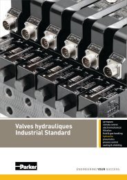
Figure 6. Liquid-to-liquid condenser module installed in demonstrator system<br />
with additional sensors and metering components.<br />
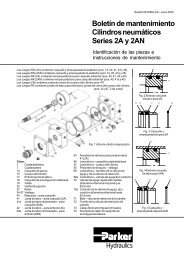
Figure 7. Multiple dielectric fluid pumps in module with quick-disconnects.<br />
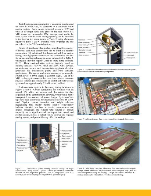
Figure 8. VDF liquid cold plate, illustrating fluid manifolding and flow path<br />
through copper convoluted fin packs within brass cold plate body (prior to<br />
final cover plate assembly and brazing). Design for 140mm x 130mm <strong>IGBT</strong><br />
module mounting for vehicle HEV powertrain inverter testing.