Bedienungsanleitung KXE - REITZ Ventilatoren
Bedienungsanleitung KXE - REITZ Ventilatoren
Bedienungsanleitung KXE - REITZ Ventilatoren

Create successful ePaper yourself
Turn your PDF publications into a flip-book with our unique Google optimized e-Paper software.
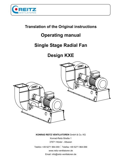
Translation of the Original instructions<br />
Operating manual<br />
Single Stage Radial Fan<br />
Design <strong>KXE</strong><br />
KONRAD <strong>REITZ</strong> VENTILATOREN GmbH & Co. KG<br />
Konrad-Reitz-Straße 1<br />
37671 Höxter - Albaxen<br />
Telefon +49 5271 964-000 � Telefax +49 5271 964-069<br />
www.reitz-ventilatoren.de<br />
Email: info@reitz-ventilatoren.de
Customer Service<br />
Konrad Reitz <strong>Ventilatoren</strong> GmbH & Co. KG<br />
Konrad-Reitz-Straße 1<br />
37671 Höxter – Albaxen<br />
Germany<br />
telephone: +49 5271 964-000 (switchboard)<br />
telephone: +49 5271 964-213 (after-sales-service)<br />
telefax: +49 5271 964-269 (after-sales-service)<br />
OPERATING MANUAL: RADIAL FAN <strong>KXE</strong><br />
� 2009 KONRAD <strong>REITZ</strong> VENTILATOREN GmbH & Co. KG<br />
Copyright on the operating manual<br />
Please read this operating manual carefully. In case of<br />
doubts or if uncertain points occur, please clarify them with<br />
Konrad Reitz <strong>Ventilatoren</strong> GmbH & Co. KG first.<br />
The operating manual is, like spare parts lists and documentations<br />
of sub-suppliers, a separate part of the complete documentation.<br />
The complete documentation must be made<br />
available to the personnel appointed to operating and maintenance<br />
works.<br />
KONRAD <strong>REITZ</strong> VENTILATOREN GmbH & Co. KG holds the copyright in this operating manual.<br />
This operating manual is intended for technical personnel that performs the following work related to the<br />
fan: transport, mounting, commissioning and start-up, operation, operating, troubleshooting, maintenance,<br />
repair, shutting-down, dismantling, disposal. Instructions and drawings of technical nature must<br />
not be copied in parts or completely, distributed or used without authorization for the purpose of competition<br />
or information of third parties.<br />
This operating manual was drawn up with the utmost care. KONRAD <strong>REITZ</strong> VENTILATOREN GmbH &<br />
Co. KG is not liable for possible errors in this operating manual. Liabilities for indirect and / or direct<br />
damages that are related to the delivery or the usage of this operating manual are excluded, as far as<br />
legally permitted.<br />
BWA-<strong>KXE</strong>-Fetteinzelstehlager_englisch_02.doc as at 12/2009
Table of contents<br />
Table of contents<br />
1. Introduction ................................................................................................................ 1.1<br />
1.1 EC Declaration of conformity and EC Declaration of incorporation ...........................................1.1<br />
1.2 Fan data sheet ...........................................................................................................................1.1<br />
1.3 Description .................................................................................................................................1.2<br />
1.4 Intended use ..............................................................................................................................1.2<br />
1.5 Installations and mounting instructions to reduce noise and vibrations .....................................1.3<br />
1.6 General remarks ........................................................................................................................1.4<br />
1.7 Nameplate..................................................................................................................................1.6<br />
2. Safety instructions..................................................................................................... 2.1<br />
2.1 General remarks ........................................................................................................................2.1<br />
2.2 Danger outline............................................................................................................................2.1<br />
2.3 Symbols .....................................................................................................................................2.2<br />
2.4 Safety regulations ......................................................................................................................2.4<br />
2.5 Regulations, standards ..............................................................................................................2.5<br />
2.6 Electric connection conditions....................................................................................................2.6<br />
2.7 Marking, danger signs................................................................................................................2.7<br />
2.8 Qualified person.........................................................................................................................2.7<br />
2.9 Personal protective equipment...................................................................................................2.8<br />
2.10 Risk of slipping, tripping or falling...............................................................................................2.9<br />
2.11 Measures in case of electrical power outage.............................................................................2.9<br />
3. Transport, Installation ............................................................................................... 3.1<br />
3.1 General remarks ........................................................................................................................3.1<br />
3.2 Safety instructions......................................................................................................................3.1<br />
3.3 Regulations, standards ..............................................................................................................3.2<br />
3.3.1 Load suspension devices...........................................................................................................3.3<br />
3.4 Packing ......................................................................................................................................3.4<br />
3.5 Transport....................................................................................................................................3.5<br />
3.5.1 Transport damages....................................................................................................................3.6<br />
3.5.2 Intermediate storage ..................................................................................................................3.6<br />
3.6 Installation..................................................................................................................................3.7<br />
3.6.1 General remarks ........................................................................................................................3.7<br />
3.6.2 Safety instructions......................................................................................................................3.7<br />
3.6.3 Preparation for installation .........................................................................................................3.8<br />
3.6.4 Mounting and Alignment ............................................................................................................3.9<br />
3.6.4.1 General remarks ........................................................................................................................3.9<br />
3.6.4.2 Sequence of mounting ...............................................................................................................3.9<br />
3.6.4.3 Alignment of the shafts.............................................................................................................3.11<br />
3.7 Connections .............................................................................................................................3.14<br />
3.7.1 General remarks ......................................................................................................................3.14<br />
3.7.2 Safety instructions....................................................................................................................3.14<br />
3.7.3 Ducting of fan...........................................................................................................................3.15<br />
3.7.4 Check of clearances.................................................................................................................3.15<br />
BWA-<strong>KXE</strong>-Fetteinzelstehlager_englisch_02.doc<br />
1
Table of contents<br />
3.7.5 Use of flexible connections ......................................................................................................3.16<br />
3.7.5.1 Installation of flexible connections............................................................................................3.16<br />
3.7.6 Use of chutes ...........................................................................................................................3.16<br />
3.7.7 Electric connection conditions..................................................................................................3.17<br />
3.7.7.1 Earthing....................................................................................................................................3.17<br />
3.7.7.2 Monitoring devices ...................................................................................................................3.18<br />
3.7.8 Lubrication ...............................................................................................................................3.18<br />
3.7.9 Seal connection .......................................................................................................................3.19<br />
4. Start-up ....................................................................................................................... 4.1<br />
4.1 General remarks ........................................................................................................................4.1<br />
4.2 Mechanical check.......................................................................................................................4.1<br />
4.2.1 Alignment ...................................................................................................................................4.1<br />
4.3 Electric check.............................................................................................................................4.1<br />
4.3.1 Monitoring devices / auxiliary equipment ...................................................................................4.1<br />
4.3.2 Check of sense of rotation .........................................................................................................4.2<br />
4.3.3 Commutating wrong sense of rotation .......................................................................................4.2<br />
4.4 Start-up of fan ............................................................................................................................4.3<br />
4.4.1 General remarks ........................................................................................................................4.3<br />
4.4.2 Safety instructions......................................................................................................................4.3<br />
4.4.3 Switching on of the fan...............................................................................................................4.4<br />
4.4.3.1 Direct starting.............................................................................................................................4.5<br />
4.4.3.2 Star-delta-starting.......................................................................................................................4.5<br />
4.4.3.3 Prevention of high negative torque impacts during test run.......................................................4.5<br />
4.4.4 Disconnecting of fan ..................................................................................................................4.5<br />
5. Operation, Operating ................................................................................................. 5.1<br />
5.1 General remarks ........................................................................................................................5.1<br />
5.2 Safety instructions......................................................................................................................5.1<br />
5.3 Operational performance of the fan ...........................................................................................5.1<br />
5.4 Disconnecting of fan ..................................................................................................................5.1<br />
6. Trouble, Repair........................................................................................................... 6.1<br />
6.1 General remarks ........................................................................................................................6.1<br />
6.2 Safety instructions......................................................................................................................6.1<br />
6.3 Troubles .....................................................................................................................................6.2<br />
6.3.1 Bearing troubles.........................................................................................................................6.3<br />
6.3.2 Coupling troubles .......................................................................................................................6.3<br />
7. Maintenance ............................................................................................................... 7.1<br />
7.1 General remarks ........................................................................................................................7.1<br />
7.2 Safety instructions......................................................................................................................7.1<br />
7.3 Bearings.....................................................................................................................................7.2<br />
7.3.1 Anti-friction bearings ..................................................................................................................7.2<br />
7.3.1.1 Lubrication instructions anti-friction bearings.............................................................................7.3<br />
7.3.1.2 Lubrication intervals ...................................................................................................................7.3<br />
7.4 Shaft seal ...................................................................................................................................7.5<br />
BWA-<strong>KXE</strong>-Fetteinzelstehlager_englisch_02.doc<br />
2
BWA-<strong>KXE</strong>-Fetteinzelstehlager_englisch_02.doc<br />
Table of contents<br />
7.4.1 Standard seal.............................................................................................................................7.5<br />
7.4.2 Shaft seal with graphite ring.......................................................................................................7.5<br />
7.4.3 Seal with special rings................................................................................................................7.6<br />
7.4.4 Shaft seal with grease barrier ....................................................................................................7.6<br />
7.4.5 Shaft seal with sealing gas.........................................................................................................7.6<br />
7.5 Coupling.....................................................................................................................................7.7<br />
7.5.1 Alignment ...................................................................................................................................7.7<br />
7.6 Marking, information sign...........................................................................................................7.8<br />
7.7 Waste disposal...........................................................................................................................7.8<br />
7.8 Revison ......................................................................................................................................7.8<br />
7.9 Maintenance schedule ...............................................................................................................7.9<br />
8. Repair work................................................................................................................. 8.1<br />
8.1 General remarks ........................................................................................................................8.1<br />
8.2 Safety instructions......................................................................................................................8.1<br />
8.3 Spare parts ................................................................................................................................8.2<br />
9. Annex .......................................................................................................................... 9.1<br />
9.1 Additional technical information .................................................................................................9.1<br />
9.1.1 Tightening moments for fastening screws..................................................................................9.1<br />
9.1.2 Limiting values vibrations...........................................................................................................9.2<br />
9.1.3 Limiting values bearing temperatures ........................................................................................9.3<br />
9.2 Requests regarding field service staff........................................................................................9.4<br />
10. Fan shutdown........................................................................................................... 10.1<br />
10.1 General remarks ......................................................................................................................10.1<br />
10.2 Safety instructions....................................................................................................................10.1<br />
10.3 Measures in case of prolonged shutdown................................................................................10.2<br />
10.4 Measures in case of re-commissioning....................................................................................10.3<br />
11. Dismantling............................................................................................................... 11.1<br />
11.1 General remarks ......................................................................................................................11.1<br />
11.2 Safety instructions....................................................................................................................11.1<br />
12. Safety data sheets.................................................................................................... 12.1<br />
13. Expiry of service life, disposal................................................................................ 13.1<br />
3
1. Introduction<br />
1.1 EC Declaration of conformity and<br />
EC Declaration of incorporation<br />
1.2 Fan data sheet<br />
BWA-<strong>KXE</strong>-Fetteinzelstehlager_englisch_02.doc<br />
Introduction<br />
Being part of the overall documentation, these documents<br />
are attached as separate documents to this operating<br />
manual (see enclosure).<br />
The fan data sheet (see enclosure) is also attached in the<br />
form of a separate document to this operating manual. All<br />
relevant technical data of the fan is clearly represented in the<br />
fan data sheet. It may also be called technical data sheet<br />
and is generated for each individual fan.<br />
The fan data sheet contains the following information:<br />
- Serial fan number<br />
- Fan type<br />
- Flow data (nominal data and operating points)<br />
- Motor data<br />
- Acoustic data<br />
- Material data<br />
- Type of coating<br />
- Bearing details<br />
- Details about V-belt drive or coupling<br />
- Fan equipment and accessories<br />
- Customer’s order number<br />
- Customer’s type designation<br />
1.1
1.3 Description<br />
1.4 Intended use<br />
BWA-<strong>KXE</strong>-Fetteinzelstehlager_englisch_02.doc<br />
Introduction<br />
The fan of <strong>KXE</strong> design is a welded single-stage radial fan.<br />
Power is transmitted from motor shaft to fan shaft by a<br />
flexible coupling.<br />
The fan shaft runs in two grease-lubricated anti-friction bearings<br />
in single bearing housings.<br />
Further technical information that is not covered by this operating<br />
manual must be requested from the manufacturer.<br />
The fan is designed, calculated, produced, tested and<br />
delivered in accordance with the design conditions stated in<br />
the order.<br />
The values given in the fan data sheet must not be exceeded.<br />
Any other or exceeding use is considered to be improper<br />
use. Damages resulting from improper use are excluded<br />
from the manufacturer’s liability.<br />
1.2
1.5 Installations and mounting<br />
instructions to reduce noise and<br />
vibrations<br />
BWA-<strong>KXE</strong>-Fetteinzelstehlager_englisch_02.doc<br />
Introduction<br />
Take the following measures to reduce noise and to protect<br />
the operating personnel’s health:<br />
- Connect the fan to the duct work at inlet and discharge<br />
prior to fan start-up<br />
- Mount the sound protection covers and hoods for<br />
motor and bearing (if included in the delivery)<br />
- Isolate the housing on-site if the fan is prepared for<br />
insulation and this is included in the delivery<br />
- Wear personal protective equipment (especially ear<br />
protection) � see also chapter 2.2 Danger outline<br />
Take the following measures to reduce the vibrations and to<br />
avoid the transmission of vibrations to the duct work:<br />
- Check the impeller according to the maintenance plan<br />
(see chapter 7.9 Maintenance schedule) with regard to<br />
sticking material, wear and tear, etc. since out-of-balance<br />
might result in an increase in fan vibrations � see chapter<br />
9.1.2 Limiting values vibrations<br />
- Mount the flexible connections at inlet and discharge prior<br />
to fan start-up (see also chapter 3.7.5 Use of flexible connections)<br />
- Mount the fan on anti-vibration mounts (see chapter 3.6.4<br />
Mounting and Alignment)<br />
1.3
1.6 General remarks<br />
BWA-<strong>KXE</strong>-Fetteinzelstehlager_englisch_02.doc<br />
Introduction<br />
This universal operating manual assists the operating<br />
company to carry out the safe and proper transport, installation,<br />
commissioning, start-up and maintenance of the fan.<br />
This operating manual exclusively refers to the fan, but not to<br />
the electrical equipment like drive motors and other auxiliary<br />
drives. The unit “fan and motor” will not turn into electrical<br />
equipment when an electric drive is mounted. Please observe<br />
the operating and maintenance instructions of the motor<br />
manufacturer for mounting, installation and maintenance<br />
of the electric motors and auxiliary drives.<br />
This operating manual describes and represents components<br />
that may not be included in your delivery.<br />
In addition, our scope of delivery can include components<br />
and additional equipment that are not mentioned in these instructions.<br />
In that case, please observe the corresponding<br />
operating manuals of the relative producers. If applicable,<br />
request them from Konrad Reitz <strong>Ventilatoren</strong> GmbH & Co.<br />
KG.<br />
This operating manual is subject to modifications due to further<br />
technical development of the fan described herein.<br />
Many images and drawings of this operating manual are<br />
simplified representations. Due to improvements and modifications<br />
the fan operated by your company might vary from<br />
the representations.<br />
We reserve the copyright in this operating manual and the<br />
attached drawings and further documents.<br />
The manufacturer will not undertake liability for damages that<br />
� occur during the warranty period resulting from:<br />
- inadequate maintenance,<br />
- improper operating and another than the intended use<br />
- faulty mounting and installation,<br />
- incorrect or inexpert connection of electric or mechanic<br />
machines and devices.<br />
� result or originate from unauthorized modifications or from<br />
disregarding the manufacturer’s recommendations and<br />
instructions.<br />
� result from the use of accessories, equipment and/or<br />
spare parts that are not recommended by or delivered<br />
from the manufacturer.<br />
1.4
BWA-<strong>KXE</strong>-Fetteinzelstehlager_englisch_02.doc<br />
Introduction<br />
This operating manual serves to avoid personal injury, property<br />
damage, functional failure as well as environmental<br />
damage.<br />
Read these instructions carefully and completely before start<br />
of work. Should you have any questions or in case of doubts<br />
occur please do not hesitate to contact Konrad Reitz <strong>Ventilatoren</strong><br />
GmbH & Co. KG first.<br />
Keep these instructions in a safe place. They must be accessible<br />
for the operating company at any time. Protect them<br />
against harmful environmental influences and keep them in a<br />
legible and complete condition. Store them near to the fan.<br />
1.5
1.7 Nameplate<br />
BWA-<strong>KXE</strong>-Fetteinzelstehlager_englisch_02.doc<br />
The nameplate shows the following information:<br />
- Manufacturer<br />
- Address<br />
- Designation of the machine<br />
- Type designation<br />
- Serial number<br />
- Year of construction<br />
- Technical data<br />
- CE - sign<br />
Introduction<br />
If technical information is or spare parts are required, all above<br />
mentioned data must be communicated.<br />
1.6
2. Safety instructions<br />
2.1 General remarks<br />
2.2 Danger outline<br />
BWA-<strong>KXE</strong>-Fetteinzelstehlager_englisch_02.doc<br />
Safety instructions<br />
It is essential to read the operating manual prior to transport,<br />
installation, commissioning, start-up, operating, repair and<br />
maintenance. The instructions have to be observed.<br />
Radial fan – single-stage, structural design <strong>KXE</strong><br />
Kind of danger Location of danger Danger Additional measures<br />
impact and rubbing housing, bearings, impeller,<br />
motor, improper<br />
handling during transport<br />
corrosion housing, bearings, impeller,<br />
motor, improper<br />
storage or intermediate<br />
storage<br />
crushing, shearing, impact unloading, lifting, mounting<br />
and installation of the fan<br />
entangling, winding,<br />
drawing-in, trapping, faulty<br />
installation<br />
electrical hazard<br />
thermal hazard caused by<br />
contact and burn<br />
thermal hazard caused by<br />
improper installation,<br />
commissioning and startup<br />
hazard generated by<br />
materials and foreign<br />
substances and improper<br />
use<br />
high pressure ingress and<br />
ejection of fluids and gases<br />
heat flinger, impeller, all<br />
rotating parts<br />
explosion hazard by<br />
sparking and / or hot<br />
surfaces<br />
deposits of corrosion<br />
increase the risk of ignition<br />
and sparking, explosion<br />
hazard<br />
observe operating manual<br />
and transport instructions<br />
observe operating manual<br />
and storage instructions<br />
danger of injury pay attention to safe<br />
fastening and safe foundation<br />
/ floor conditions<br />
risk of property damages observe operating manual<br />
and danger of injury<br />
directly by alive parts danger to life observe motor manufacturer’s<br />
operating manual<br />
indirectly by faulty alive<br />
parts<br />
danger to life observe safety regulations<br />
hot surfaces danger of injury<br />
explosion hazard by<br />
increased risk of ignition<br />
and sparking<br />
hot surfaces danger of injury<br />
explosion hazard by<br />
increased risk of ignition<br />
and sparking<br />
housing, impeller, bearings,<br />
driving elements,<br />
monitoring devices<br />
shaft seal with purge<br />
medium connection<br />
hazard generated by noise during operation the sound<br />
emission exceeds 70 dB(A)<br />
combination of hazards danger for machinery,<br />
personnel and environment<br />
if the commissioning, startup<br />
of the fan is not carried<br />
out by sufficiently trained<br />
staff members<br />
risk of property damages<br />
and danger of injury<br />
danger of injury -<br />
impairment of hearing ability,<br />
danger of injury<br />
danger of injury, property<br />
damages, environmental<br />
damages<br />
wearing of personal<br />
protective equipment by<br />
staff, if necessary, customer<br />
must install safety<br />
areas<br />
wearing of personal<br />
protective equipment by<br />
staff, if necessary, customer<br />
must install safety<br />
areas<br />
observe operating manual,<br />
provide sufficient ventilation,<br />
avoid penetration and dragin<br />
of foreign substances<br />
wearing of personal<br />
protective equipment<br />
observe operating manual<br />
2.1
2.3 Symbols<br />
BWA-<strong>KXE</strong>-Fetteinzelstehlager_englisch_02.doc<br />
Safety instructions<br />
The following symbols used in this operating manual need to<br />
be particularly observed:<br />
Observe carefully the safety instructions that are listed next<br />
to the symbols in the following chapters. A label with these<br />
symbols and the corresponding instructions is also fixed to<br />
the fan.<br />
DANGER!<br />
Danger to life!<br />
Serious physical injury with potential fatal consequences.<br />
DANGER!<br />
Danger of death by electrocution!<br />
Serious physical injury with potential fatal consequences.<br />
Working must exclusively be carried out by authorized<br />
electrician<br />
DANGER!<br />
Risk of fatal injury from entangling, drawing-in or<br />
trapping<br />
Serious physical injury with potential fatal consequences.<br />
Beware of automatic operation<br />
DANGER!<br />
Explosion hazard!<br />
Spark formation or hot surfaces<br />
Serious physical injury with potential fatal consequences.<br />
WARNING!<br />
Very Hot Surface – Do not touch!<br />
Risk of burns. Severe personal injury<br />
WARNING!<br />
Risk of escaping of hot or dangerous gases.<br />
CAUTION!<br />
Risk related to exposure to noise!<br />
Physical injury<br />
Wear ear protection when fan is in operation.<br />
2.2
BWA-<strong>KXE</strong>-Fetteinzelstehlager_englisch_02.doc<br />
Safety instructions<br />
WARNING!<br />
Environmental harm!<br />
Considerable damage caused to the environment.<br />
NOTICE!<br />
Read the operating manual.<br />
NOTICE!<br />
Refers to useful information and explanations.<br />
2.3
2.4 Safety regulations<br />
BWA-<strong>KXE</strong>-Fetteinzelstehlager_englisch_02.doc<br />
Safety instructions<br />
The following instructions and regulations that are part of the<br />
operating manual are strictly to be observed.<br />
- safety regulations,<br />
- regulations for the prevention of accidents,<br />
- directives and accepted engineering standards.<br />
Disregarding the safety regulations causes personal injury<br />
and damage to the fan. Such disregarding causes the failures<br />
of the instructions included herein regarding transport,<br />
installation, commissioning, start-up, operation, repair and<br />
maintenance of the fan.<br />
2.4
2.5 Regulations, standards<br />
BWA-<strong>KXE</strong>-Fetteinzelstehlager_englisch_02.doc<br />
Safety instructions<br />
Working on the fan must comply with the valid rules for the<br />
prevention of accidents and the accepted engineering<br />
standards.<br />
� Betriebssicherheitsverordnung (German Health and Safety<br />
at Work Regulations (BetrSichV) – “Regulations on safety<br />
and health protection for the provision of work equipment<br />
and their use for work, on the safety of the operation<br />
of plants that require special monitoring and on the organisation<br />
of health and safety protection at factory level”<br />
(translation of the full German title).<br />
� VDMA 24165 “<strong>Ventilatoren</strong> – Sicherheitsanforderungen”<br />
(Industrial fans, safety reguirements - VDMA – Verband<br />
Deutscher Maschinen- und Anlagenbau eV – German<br />
Engineering Federation)<br />
� Regulations for the prevention of accidents (BGVs) of the<br />
“Berufsgenossenschaften (BGs)“ (institutions for statutory<br />
accident insurance and prevention in Germany)<br />
- „Grundsätze der Prävention“ BGV A1<br />
(General prescriptions) BGV A1<br />
- „Elektrische Anlagen und Betriebsmittel“ BGV A3<br />
(Electrical installations and operating material) BGV A3<br />
- „Lärm“ BGV B3 (Noise) BGV B3<br />
� Occupational Safety Regulations for safety and health at<br />
work (BG rules -BGR)<br />
- „Explosionsschutz-Regeln - Regeln für das Vermeiden<br />
der Gefahren durch explosionsfähige Atmosphäre“<br />
BGR 104 (bisher ZH 1/10).<br />
(Explosion protection regulations – regulations for the<br />
prevention of dangers caused by ignitable atmospheres<br />
BGR 104 (so far ZH1/10)<br />
- “Betreiben von Arbeitsmitteln” BGR 500, Kap. 2.8 (Use<br />
of work equipment BRG 500 chap. 2)<br />
� Harmonised European standards and national standards<br />
- EN 1127-1 „Explosive atmospheres – Explosion prevention<br />
and protection“<br />
- DIN 24166 „Technische Lieferbedingungen für <strong>Ventilatoren</strong>“<br />
(German Industrial Standard - Technical delivery conditions<br />
for fans)<br />
- DIN EN 14986 „Konstruktion von <strong>Ventilatoren</strong> für den<br />
Einsatz in explosionsgefährdeten Bereichen“<br />
(Design of fans working in potentially explosive atmospheres)^<br />
� EU Directive<br />
- 89/686/ECC “Personal protective equipment”<br />
2.5
2.6 Electric connection conditions<br />
BWA-<strong>KXE</strong>-Fetteinzelstehlager_englisch_02.doc<br />
Safety instructions<br />
The operating company has to observe the instructions and<br />
to meet the connection conditions of the local electric supply<br />
company for the electric connection of the motor and the<br />
auxiliary drives (if any) and the system.<br />
All electric works on the machine and its connections<br />
must exclusively be carried out by professional electricians<br />
that are authorized by the definition regarding<br />
professionals (e.g. German definition DIN VDE 0105<br />
and IEC 364).<br />
It has to be ensured that type of current, voltage and frequency<br />
of the electric power supply are suitable for the below<br />
enlisted components and that the electric connections<br />
are expertly made for:<br />
- drive motor/s fan<br />
- actuator/s damper/s<br />
- monitoring devices<br />
- other electric parts<br />
If the fan is of explosion-proof design, the electric installation<br />
has to meet the requirements of prEN 50154.<br />
2.6
2.7 Marking, danger signs<br />
2.8 Qualified person<br />
BWA-<strong>KXE</strong>-Fetteinzelstehlager_englisch_02.doc<br />
Safety instructions<br />
Information directly arranged on the fan, e.g. sense of<br />
rotation arrows, information signs, markings or danger signs<br />
must be observed and kept in legible condition.<br />
Qualified persons in terms of the § 2, clause 7 German<br />
Health and Safety at Work Regulations („Betriebssicherheitsverordnung<br />
BetrSichV“) is personnel that due to professional<br />
training, work experience and their current occupational<br />
activity has the necessary expert knowledge for testing<br />
the working devices.<br />
Qualified persons only are allowed to carry out all works at<br />
the fan, at fan components, at the fan equipment, maintenance<br />
devices and electric components. Authorised personnel<br />
must also have sufficient knowledge about<br />
- currently valid safety regulations,<br />
- currently valid regulations for the prevention of accidents,<br />
- directives and accepted engineering standards.<br />
In addition, qualified personnel must:<br />
- be authorized to carry out the necessary works<br />
- be able to assess the works allocated to them with regard<br />
to dangers, be able to recognize possible dangers and to<br />
avoid them.<br />
- have read these instructions prior to working<br />
The person who is responsible for the safety of the system<br />
authorises the personnel to carry out the works.<br />
2.7
2.9 Personal protective equipment<br />
BWA-<strong>KXE</strong>-Fetteinzelstehlager_englisch_02.doc<br />
Safety instructions<br />
The operating company and the plant engineering company<br />
are responsible for the required protective measures on site<br />
like coverage, barriers or personal protective equipment.<br />
Operating personnel are all staff members that are in charge<br />
of installation, mounting, operation, setting, maintenance,<br />
cleaning, repair and transport of machinery.<br />
Carrying out dangerous works and activities requires wearing<br />
personal protective equipment in terms of EU Directive<br />
89/689/EWG in order to avoid injuries or minimise the risk of<br />
injury that might not be prevented through other measures.<br />
The minimum equipment includes:<br />
- helmet<br />
- eye protection<br />
- foot guard<br />
- hand guard<br />
- ear protection<br />
- reflective jacket<br />
- appropriate working clothes.<br />
In dependence of the type of the works or their dangerousness,<br />
wearing of further personal protective equipment and<br />
taking further safety precautions (e.g. fall protection) may<br />
become necessary.<br />
When working on the fan, the following “Occupational Safety<br />
Regulations for safety and health at work (BG rules -BGR):<br />
- „Wearing of protective clothing “ BGR 189<br />
- „Wearing of foot and leg guards“ BGR 191<br />
- „Use of head protection“ BGR 193<br />
- „Use of ear protection“ BGR 194<br />
- „Wearing of protective gloves“ BGR195<br />
- „Use of protective equipment against falling“ BGR 198<br />
2.8
2.10 Risk of slipping, tripping or<br />
falling<br />
2.11 Measures in case of electrical<br />
power outage<br />
BWA-<strong>KXE</strong>-Fetteinzelstehlager_englisch_02.doc<br />
Safety instructions<br />
The operating company and the plant engineering company<br />
are responsible for necessary precautionary protective<br />
measures on site.<br />
- Mark the transport aisles and keep them clear<br />
- Sufficiently light the transport aisles and workplaces<br />
- Remove unevenness of floor and installation sites<br />
- Keep the working environment tidy and clean<br />
- Treads must be anti-slip and undamaged<br />
- Eliminate the slip danger (e.g. remove packed<br />
snow and black ice, keep the place in a dry condition)<br />
- Apply fall protection (e.g. safety harness) when<br />
ladders are used to access the workplace<br />
- There is the risk of falling from heights of more<br />
than 1 metre above the floor and in case of hollows<br />
or floor openings � install safety fence (e.g.<br />
guard railing, barriers), use fast devices instead<br />
of warning tape<br />
- Ladders cannot serve as working places. It is not<br />
allowed to carry out certain works from the ladder,<br />
when for example the ladder lacks stability,<br />
the tool’s weight exceeds 10 kg, the area exposed<br />
to wind exceeds 1 m².<br />
- Install working platforms at places that have to<br />
be maintained on a regular basis.<br />
- Spilt working material is to be removed with suitable<br />
oil binding agent. Dispose of it in a safe<br />
manner consistent with all applicable regulations.<br />
- Remove completely leaked grease and dispose<br />
of it properly and professionally in view of environmental<br />
protection requirements.<br />
In case the of and / or auxiliary electrical power failure, the<br />
fan has to be put into a safe condition. The control system<br />
must be designed so that the power breakdown or the<br />
control system itself does not result in a dangerous<br />
sitatuation, neither at the time of the mains failure nor at the<br />
time when the enery is re-established or the control system<br />
is again ready for operation.<br />
Additional measures for fans, whose handled gas<br />
temperature exceeds 80°C: In case the power fails, the hot<br />
handled gas must absolutely be prevented from flowing in at<br />
inlet of the fan and also from flowing back or backing up at<br />
discharge of the fan. Install proper shut-off devices including<br />
appropriate control systems on-site and keep them in an<br />
operable state.<br />
2.9
3. Transport, Installation<br />
3.1 General remarks<br />
3.2 Safety instructions<br />
BWA-<strong>KXE</strong>-Fetteinzelstehlager_englisch_02.doc<br />
Transport, Installation<br />
The fan and the equipment should only be transported and<br />
lifted at the provided marked lifting lugs. Load suspension<br />
devices as well as sling devices have to be in perfect condition<br />
and should only to be fastened at the provided lifting<br />
lugs.<br />
Personnel that lifts and transports the fan must:<br />
- have read the operating manual,<br />
- have understood the content of the chapter transport, especially<br />
the safety regulations, the regulations for the prevention<br />
of accidents and the instructions for the transport<br />
of the fan,<br />
- be familiar with the hoists, the required load suspension<br />
devices and the sling devices.<br />
The safety instructions for lifting and transport of the<br />
fan must be observed.<br />
- Use hoists, load suspension devices and sling<br />
devices with sufficient load capacity only (for load<br />
/ weight see fan data sheet or fan drawing)<br />
- The angle of spread must not exceed 120° (see<br />
Figure 2).<br />
- Do not knot steel wire ropes and chains.<br />
- Do not tie ropes from fibres with knots.<br />
- Do not distort the ropes.<br />
- Untwist distorted ropes prior to lifting.<br />
- Do not kink the ropes at wire rope clamps.<br />
- Thimbles (cable eye stiffeners), rope eyes, suspension<br />
hooks and other lifting links must suspend<br />
freely on the lifting hook.<br />
- Use edge guards when the slings are laid on<br />
sharp edges.<br />
- Lift up the hook tackle when it is not used.<br />
- Do not lift loads over people.<br />
Observe the regulations for the prevention of accidents.<br />
Auxiliary lifting lugs (e.g. at the motor) – if any – are suitable<br />
only for lifting the corresponding single component.<br />
We recommend an installation performed by<br />
manufacturer’s skilled staff.<br />
3.1
3.3 Regulations, standards<br />
BWA-<strong>KXE</strong>-Fetteinzelstehlager_englisch_02.doc<br />
Transport, Installation<br />
The valid regulations for the prevention of accidents and the<br />
accepted engineering standards apply to the lifting and<br />
transport of the fan.<br />
� Regulations for the prevention of accidents (e.g. German<br />
BG regulations)<br />
- „Allgemeine Vorschriften“ (General Instructions)<br />
BGV A1<br />
- „Krane“ (Cranes) BGV D6 (VBG 9)<br />
- “Betreiben von Arbeitsmitteln” BGR 500, Kap. 2.8 (Use<br />
of work equipment BRG 500 chap. 2)<br />
� National standards (e.g. Standards of the German Institute<br />
for Standardisation)<br />
- „Hebezeuge, Lastaufnahmeeinrichtungen“ (Hoists, load<br />
suspension devices ) DIN 15003<br />
- „Ösenhaken, Güteklasse 5“ (Eye hooks, quality class<br />
5) DIN 7540<br />
- „Schäkel“ (Shackles) DIN 82101<br />
3.2
BWA-<strong>KXE</strong>-Fetteinzelstehlager_englisch_02.doc<br />
Transport, Installation<br />
3.3.1 Load suspension devices � Fans are only to be lifted and transported with the<br />
appropriate hoists and means of transport (weight<br />
indication see fan data sheet or fan drawing).<br />
Figure 1<br />
transport and lifting lugs<br />
spread and inclination angle<br />
αN<br />
Figure 2<br />
αS<br />
load<br />
� Fasten sling devices only at the especially provided<br />
lifting lugs (see Figure 1)<br />
� Do not damage components or fan when fastening<br />
sling devices.<br />
� Do not fasten sling devices to the inlet, discharge,<br />
bearings, motor or base frame.<br />
This damages the fan and excludes and limits<br />
the liability of the manufacturer.<br />
� Sling devices must be of the same length. Pay<br />
attention to an even load distribution.<br />
� Observe the spread angle and the inclination angle<br />
(see Figure 2)<br />
The inclination angle αN must not exceed 60°,<br />
that is to say the spread angle αS must not exceed<br />
120°.<br />
� Wear personal protective equipment (see chapter<br />
2.9)<br />
3.3
3.4 Packing<br />
Figure 3<br />
BWA-<strong>KXE</strong>-Fetteinzelstehlager_englisch_02.doc<br />
Transport, Installation<br />
The fan and the equipment are packed in the factory in<br />
accordance with<br />
- the transport route,<br />
- the storage at customer’s premises<br />
- and / or customer’s requirements<br />
Types of packing:<br />
� Fan components mounted on wooden pallet with protection<br />
covering (welded in plastic foil).<br />
� Fan components mounted on wooden pallet with protection<br />
covering (welded in plastic foil) and special bearing<br />
protection.<br />
� Fan components mounted on wooden crate, protection<br />
covering (welded in plastic foil) and special bearing protection.<br />
� Seaworthy packing in closed wooden case � Figure 3).<br />
Fan components must only be transported with transport<br />
safety contrivances, with a protection covering (foil) and<br />
desiccants, so that no dirt and humidity can enter in the<br />
fan, in the anti-friction bearings or in the electric components.<br />
The protection covering must be removed prior to that installation<br />
of the fan components.<br />
Symbol legend:<br />
Keep dry<br />
This side up<br />
Glass - fragile<br />
Centre of gravity<br />
Fasten sling devices here<br />
In case the fan or the equipment is packed and corrosion<br />
protected for an extended period of time at the factory, the<br />
separate „Instructions for Storage and Corrosion Protection<br />
of Radial Fans“ must be observed.<br />
3.4
3.5 Transport<br />
BWA-<strong>KXE</strong>-Fetteinzelstehlager_englisch_02.doc<br />
Transport, Installation<br />
For lifting and transport of the fan components and<br />
the equipment observe<br />
- 2.4 Safety regulations,<br />
- 2.5 Regulations, standards,<br />
- 3.3.1 Load suspension devices<br />
� Sling devices, e.g.<br />
- wire ropes,<br />
- ropes from fibres,<br />
- steel cables<br />
must be fixed at lifting lugs and suspension hooks.<br />
� Unload the fan with suitable hoists only. Disregard of this<br />
instruction may cause the danger of crushing or shearing<br />
of parts of the body.<br />
Cautiously place the fan onto the floor or foundation<br />
to avoid damages to the fan, the bearings and other<br />
components.<br />
� Observe permitted ground, floor, foundation or ceiling<br />
load capacities.<br />
� After unloading of fan components and equipment<br />
- remove packing (depending on type of packing),<br />
- check fan and equipment for damages,<br />
- check accessories for completeness in accordance<br />
with the delivery note.<br />
� Transport the fan components and the equipment by suitable<br />
hoists / means of transport to the installation location<br />
or storage place only.<br />
� If the fan is transported to the installation location by vehicle:<br />
- lift the fan with suitable hoists onto the platform of the<br />
vehicle,<br />
- secure the fan against shifting and displacing by fastening<br />
belts.<br />
3.5
3.5.1 Transport damages<br />
3.5.2 Intermediate storage<br />
BWA-<strong>KXE</strong>-Fetteinzelstehlager_englisch_02.doc<br />
Transport, Installation<br />
Document and immediately report any transport damages to<br />
the forwarding agent, insurance company and manufacturer.<br />
Please observe our separate “Instructions for Storage and<br />
Corrosion Protection” for proper storage of fan, bearings,<br />
shaft seal, V-belts, coupling, drives, actuators, monitoring<br />
devices and other equipment.<br />
3.6
3.6 Installation<br />
BWA-<strong>KXE</strong>-Fetteinzelstehlager_englisch_02.doc<br />
Transport, Installation<br />
If the fan is not delivered in a completely assembled condition,<br />
observe the separate mounting instructions for the<br />
assembly of fan which can be ordered from Konrad Reitz<br />
<strong>Ventilatoren</strong> GmbH & Co. KG.<br />
3.6.1 General remarks � Design conditions<br />
The fan and the equipment are designed, tested and delivered<br />
in accordance with the design conditions specified<br />
in the order.<br />
The specifications made in the order are documented in<br />
the fan data sheet. It is not permitted to deviate from the<br />
conditions shown in the fan data sheet (e.g. different handled<br />
gas).<br />
3.6.2 Safety instructions<br />
Unless otherwise agreed upon, the electric components of<br />
the machine are designed for a maximum ambient temperature<br />
of 40°C and an altitude of site up to 1000 m asl<br />
in accordance with the instructions of the German standard<br />
VDE0530.. Please observe the installation instructions<br />
in the operating manual of the motor producers.<br />
� Warranty<br />
The warranty details refer to sing values and testing conditions<br />
in accordance with the applicable EN DIN standards<br />
and/or the valid standards and regulations. The<br />
system’s specific special characteristics and local conditions<br />
must be taken into account by the system designer<br />
or the project engineer when the order data are specified.<br />
It is essential to convert the data for the operating<br />
conditions in accordance with the existing local conditions.<br />
Installation works must exclusively be carried out by specialist<br />
personnel (see chapter 2.8)<br />
It is recommended to request installation specialists<br />
of the manufacturer.<br />
3.7
BWA-<strong>KXE</strong>-Fetteinzelstehlager_englisch_02.doc<br />
Transport, Installation<br />
3.6.3 Preparation for installation � Substructure of the fan like base plates, additional base<br />
frames, sole plates, steel stages or foundations must:<br />
- be designed in accordance with the weight and the<br />
foundation load (� dimension sheet),<br />
- ensure a vibration-free installation for operation or<br />
standstill.<br />
� Compare foundation dimensions with the fan dimension<br />
sheet and the foundation plan and ensure that:<br />
- there is sufficient space for installation, maintenance<br />
and repair works,<br />
- there is sufficient space for the intake and discharge of<br />
the cooling air for the rotary current motor.<br />
� Carry out required corrections on the foundation and clean<br />
treated surfaces.<br />
� Transport fan to the location of installation by suitable<br />
hoists / means of transport (see chapter 3.3.1 Load suspension<br />
devices)<br />
3.8
3.6.4 Mounting and Alignment<br />
3.6.4.1 General remarks<br />
BWA-<strong>KXE</strong>-Fetteinzelstehlager_englisch_02.doc<br />
Transport, Installation<br />
Stability of fan is at risk when the installation site is<br />
not even. This might increase the danger of crushing<br />
and shearing of parts of the body.<br />
Prior to the start of the installation the mounting place<br />
has to be checked for evenness and dimension accuracy.<br />
Steel foundations, foundation blocks and concrete<br />
foundations that guarantee a safe operation free from<br />
impact, vibration and distortion are appropriate substructures<br />
for the fan.<br />
Assembling auxiliaries like alignment plates, fastening<br />
screws, etc. can be obtained from the manufacturer.<br />
Request installation specialists from the manufacturer,<br />
if necessary.<br />
After mounting on the foundation the fan must be aligned.<br />
Use appropriate measuring instruments, tools, jack screws<br />
and shims for this work.<br />
If the fan is installed within chemically aggressive atmosphere<br />
or outdoor � use alignment sheets made<br />
of rustproof material.<br />
3.6.4.2 Sequence of mounting � Fan without anti-vibration mounts and mounting on<br />
steel foundation<br />
Align the fan horizontally (if necessary, use alignment<br />
plates) and fasten the fan with hexagon head screws.<br />
For tightening moments see chapter 9.1.1 Tightening<br />
moments for fastening screws<br />
� Fan without anti-vibration mounts and mounting on<br />
concrete foundation<br />
Align the fan horizontally (if necessary, use alignment<br />
plates) and screw the fan to the concrete foundation with<br />
suitable fastening devices (e.g. heavy duty anchor bolts,<br />
stone bolts).<br />
For tightening moments see chapter 9.1.1 Tightening<br />
moments for fastening screws<br />
3.9
BWA-<strong>KXE</strong>-Fetteinzelstehlager_englisch_02.doc<br />
Transport, Installation<br />
� Fan with anti-vibration mounts and mounting on steel<br />
foundation<br />
- Anti-vibration mounts without mounting plate<br />
- Screw the anti-vibration mounts to the steel foundation<br />
- Carefully place the fan on the anti-vibration mounts<br />
(correctly fit the set screw in the bore holes)<br />
- Align the fan and screw it to the steel foundation.<br />
- Anti-vibration mounts with mounting plate<br />
- Carefully place the fan including the anti-vibration<br />
mounts on the steel foundation<br />
- Align the fan and screw it to the steel foundation.<br />
- Anti-vibration mounts (spring type) – spring phonolators<br />
- Screw the anti-vibration mounts (spring type) to the<br />
steel foundation<br />
- Carefully place the fan on the anti-vibration mounts<br />
(spring type), correctly fit the set screw in the bore<br />
holes.<br />
- Align the fan and screw it to the steel foundation.<br />
- Observe the mounting instructions of the producer<br />
of the anti-vibration mounts (spring type), which can<br />
be obtained from Konrad Reitz <strong>Ventilatoren</strong> GmbH<br />
& Co. KG<br />
� Fan with anti-vibration mounts and mounting on contrete<br />
foundation<br />
- Anti-vibration mount with mounting plate<br />
- Carefully place the fan including the anti-vibration<br />
mounts on the concrete foundation<br />
- Align the fan and bore the foundation holes for the<br />
heavy duty anchor bolts through the bores provided<br />
on the mounting plates.<br />
- Screw the fan to the concrete foundation with suitable<br />
fastening devices (e.g. heavy duty anchor<br />
bolts, stone bolts). and observe the tightening moments<br />
� see chapter 9.1.1<br />
- Anti-vibration mounts (spring type) – spring phonolators<br />
- Screw the anti-vibration mounts (spring type) to the<br />
concrete foundation<br />
- Carefully place the fan on the anti-vibration mounts<br />
(spring type), correctly fit the set screw in the bore<br />
holes.<br />
- Observe the mounting instructions of the producer<br />
of the anti-vibration mounts (spring type), which can<br />
be obtained from Konrad Reitz <strong>Ventilatoren</strong> GmbH<br />
& Co. KG<br />
3.10
3.6.4.3 Alignment of the shafts<br />
Figure 4<br />
BWA-<strong>KXE</strong>-Fetteinzelstehlager_englisch_02.doc<br />
Transport, Installation<br />
During transport motor and bearing can get displaced.<br />
The shafts of fan and motor must be aligned. Therefore,<br />
check the shafting for proper alignment prior to the first startup<br />
and re-align it if necessary.<br />
Manufacturer’s skilled service staff has to be requested<br />
for alignment.<br />
� Remove protection cover of coupling (fan bearings / motor).<br />
� Check the alignment of the motor to the bearings with appropriate<br />
measuring tools.<br />
- During alignment, the angular offset and the radial offset<br />
of the shaft ends must be kept as small as possible.<br />
- Permissible offset � table „Standard values for permissible<br />
shaft offsets and gap widths“.<br />
- Align the coupling in two opposite, vertically arranged,<br />
axial planes.<br />
- Check the radial offset (� Kr) with a ruler. Check the<br />
angular offset (� Kw) with a thickness gauge (feeler<br />
gauge).<br />
The accuracy of alignment can be improved by use<br />
of a dial gauge respectively by use of a laser optical<br />
sensor.<br />
Figure 4 � Permissible offset<br />
3.11
BWA-<strong>KXE</strong>-Fetteinzelstehlager_englisch_02.doc<br />
Transport, Installation<br />
The maximum permitted offsets indicated in the table are<br />
general standard values.<br />
Special applications with high demands regarding the quiet<br />
running or with higher speeds can require accuracies of alignment<br />
of � 0,1 mm for each of the three offset levels.<br />
Size of coupling<br />
Series N-Eupex Typ A,B 80 95 110 125 140 180 200 225 250 280 315 350 400 440<br />
n axial clearance s1 mm 3 3 3 3 3 4 4 4 5,5 5,5 5,5 5,5 5,5 7,5<br />
min -1 axial offset �Ka mm � 1 � 1 � 1 � 1 � 1 �2 �2 �2 �2,5 �2,5 �2,5 �2,5 �2,5 �2,5<br />
radial offset �Kr mm<br />
3000<br />
angular offset �Kw Grad<br />
0,15 0,15 0,15 0,15<br />
0,1 0,1 0,1 0,1<br />
0,2<br />
0,1<br />
0,2<br />
0,1<br />
0,2 0,25<br />
0,1 0,1<br />
-<br />
-<br />
-<br />
-<br />
-<br />
-<br />
-<br />
-<br />
-<br />
-<br />
-<br />
-<br />
radial offset<br />
1500<br />
angular offset<br />
�Kr mm<br />
�Kw Grad<br />
0,2<br />
0,1<br />
0,2<br />
0,1<br />
0,2 0,25<br />
0,1 0,1<br />
0,3<br />
0,1<br />
0,3<br />
0,1<br />
0,3 0,35 0,35 0,4<br />
0,1 0,1 0,1 0,1<br />
0,4<br />
0,1<br />
0,5<br />
0,1<br />
0,5<br />
0,1<br />
0,6<br />
0,1<br />
radial offset �Kr<br />
1000<br />
angular offset�� �Kw<br />
mm<br />
Grad<br />
0,2 0,25 0,25 0,25<br />
0,1 0,1 0,1 0,1<br />
0,3 0,35<br />
0,1 0,1<br />
0,4<br />
0,1<br />
0,4<br />
0,1<br />
0,4<br />
0,1<br />
0,5<br />
0,1<br />
0,5<br />
0,1<br />
0,6<br />
0,1<br />
0,6<br />
0,1<br />
0,7<br />
0,1<br />
Size of coupling<br />
Series ELCO Typ N / W 98 113 123 129 149 161 184 210 214 215 222 228 231 237<br />
n axial clearance s1 mm 3 3 3 3 2 2 2 2 2,5 2,5 3 3 3 3<br />
min -1 axial offset �Ka mm +2 +2 +2 +2 +2 +2 +2 +2 +2,5 +2,5 +3 +3 +3 +3<br />
radial offset �Kr mm<br />
3000<br />
angular offset �Kw Grad<br />
0,15 0,15 0,15 0,15<br />
0,1 0,1 0,1 0,1<br />
0,2<br />
0,1<br />
0,2<br />
0,1<br />
0,2<br />
0,1<br />
0,2 0,25 0,25 0,3<br />
0,1 0,1 0,1 0,1<br />
0,3<br />
0,1<br />
0,3<br />
0,1<br />
0,3<br />
0,1<br />
radial offset<br />
1500<br />
angular offset<br />
�Kr mm<br />
�Kw Grad<br />
0,2<br />
0,1<br />
0,2 0,25 0,25<br />
0,1 0,1 0,1<br />
0,3<br />
0,1<br />
0,3<br />
0,1<br />
0,3<br />
0,1<br />
0,3 0,35 0,35 0,4<br />
0,1 0,1 0,1 0,1<br />
0,4<br />
0,1<br />
0,4<br />
0,1<br />
0,4<br />
0,1<br />
radial offset �Kr<br />
1000<br />
angular offset �Kw<br />
mm 0,25 0,25 0,3 0,3 0,35 0,35<br />
Grad 0,15 0,15 0,15 0,15 0,1 0,1<br />
0,4<br />
0,1<br />
0,4<br />
0,1<br />
0,4<br />
0,1<br />
0,4<br />
0,1<br />
0,5<br />
0,1<br />
0,5<br />
0,1<br />
0,5<br />
0,1<br />
0,5<br />
0,1<br />
Size of coupling<br />
Series RUPEX RWN/RWS 162 178 198 228 252 285 320 360 400 450 500 560 630 710<br />
n axial clearance. s1 mm 3 3 3 3 3 3 4,5 4,5 4,5 5,5 5,5 5,5 5,5 7<br />
min -1<br />
axial offset<br />
3000 radial offset<br />
�Ka mm<br />
�Kr<br />
0,2 0,2 0,2 0,2 0,25 0,3 0,3 0,35 - - - - - -<br />
angular offset �Kw Grad 0,07 0,07 0,06 0,06 0,06 0,06 0,06 0,05 - - - - - -<br />
axial offset<br />
1500 radial offset<br />
�Ka mm<br />
�Kr<br />
0,25 0,25 0,3 0,35 0,35 0,4 0,45 0,5 0,5 0,55 0,6 0,7 0,75 0,85<br />
angular offset �Kw Grad 0,1 0,09 0,09 0,08 0,08 0,08 0,08 0,07 0,07 0,07 0,07 0,07 0,07 0,07<br />
axial offset �Ka<br />
1000 radial offset �Kr<br />
mm 0,3 0,35 0,35 0,4 0,45 0,5 0,55 0,6 0,65 0,7 0,75 0,85 0,9 1,0<br />
angular offset �Kw Grad 0,12 0,12 0,11 0,11 0,1 0,1 0,09 0,09 0,09 0,09 0,09 0,08 0,08 0,08<br />
If a special coupling is used, refer to the instructions<br />
specified in the annex.<br />
3.12
BWA-<strong>KXE</strong>-Fetteinzelstehlager_englisch_02.doc<br />
Transport, Installation<br />
Angular and radial offset can occur simultaneously. The total<br />
of these two offsets must not exceed the maximum permissible<br />
value of the angular offset or the radial offset.<br />
(�Kr + s1) existing � �Kr and/or s1<br />
� If the determined measurements are within the tolerance,<br />
check the fastening screws of the motor for tight connection.<br />
� If the determined measurements exceed the tolerance, readjust<br />
the fan.<br />
� Upon completion of the alignment the motor fastening<br />
screws must be screwed down with the relevant tightening<br />
moment ( � chapter 9.1.1)<br />
3.13
3.7 Connections<br />
3.7.1 General remarks<br />
3.7.2 Safety instructions<br />
BWA-<strong>KXE</strong>-Fetteinzelstehlager_englisch_02.doc<br />
Transport, Installation<br />
The connection of the electric components of the fan must<br />
be carried out in accordance with the following regulations,<br />
as amended:<br />
- Regulations issued by the local electric supply company<br />
(e.g. German EVU),<br />
- national associations for electronic regulations (eg. EN<br />
DIN VDE regulations: VDE – German Association for<br />
Electrical, Electronic & Information Technologies.)<br />
- Installation and mounting instructions in the operating<br />
manual of the motor producer.<br />
Works on the fan or the equipment must exclusively be<br />
carried out by specialist personnel, that due to professional<br />
training, experiences and instructions has sufficient knowledge<br />
about:<br />
- Safety regulations,<br />
- regulations for prevention of accidents,<br />
- directives and accepted engineering standards<br />
(e.g. VDE directives, DIN EN standards)<br />
The specialist personnel must:<br />
- be able to assess the works allocated to them, to recognize<br />
possible dangers and to avoid them,<br />
- be authorized by the person who is responsible for the safety<br />
of the system to carry out the required works and<br />
tasks.<br />
All electric works on the components of the fan must exclusively<br />
be carried out by professional electricians that are authorized<br />
by definition regarding professionals (e.g. German<br />
definition DIN VDE 0105 and IEC 364). The electricians must<br />
observe the following regulations and instructions, as amended:<br />
- EN DIN VDE-regulations (e.g. Germany),<br />
- IEC-regulations (International Electrotechnical Association),<br />
- Safety instructions,<br />
- Transport, installation and maintenance instructions<br />
Professional electricians are specialists, who due to professional<br />
training, experiences and instructions have knowledge<br />
about valid appropriate standards, regulations and regulations<br />
for prevention of accidents.<br />
Furthermore they must be able to assess the works allocated<br />
to them and to recognize and to eliminate possible dangers.<br />
The professional electricians must be authorized by the person<br />
who is responsible for the safety of the system to carry<br />
out the required works and tasks.<br />
3.14
3.7.3 Ducting of fan<br />
3.7.4 Check of clearances<br />
BWA-<strong>KXE</strong>-Fetteinzelstehlager_englisch_02.doc<br />
Transport, Installation<br />
Distortions of the fan at the connections caused by<br />
the ductwork are not permitted. Distortions cause<br />
alterations, e.g. the gap at the nozzle decreases at<br />
one side which might lead to rubbing in the inlet.<br />
- Remove the transport covers from the connections.<br />
- Move the duct work to be connected to the inlet and discharge<br />
openings of the fan without causing offsets between<br />
the ducts and openings.<br />
- Connect duct and conduits to the fan free-of-load.<br />
The radial clearance within the inlet must be checked. The<br />
minimum clearance must amount to 3 mm at least.<br />
5*<br />
4<br />
Figure 5<br />
1<br />
3<br />
2<br />
inlet cone<br />
impeller nozzle<br />
* according to the number of blades, min. 4 x (each 90°)<br />
Figure 5 �. Representation of the check<br />
points � to �<br />
At the beginning of the gap check, take the gap width at<br />
eight different points. Then turn the impeller by 90° and<br />
again check the gap at eight different points. Repeat this<br />
process three times.<br />
3.15
3.7.5 Use of flexible connections<br />
3.7.5.1 Installation of flexible<br />
connections<br />
3.7.6 Use of chutes<br />
BWA-<strong>KXE</strong>-Fetteinzelstehlager_englisch_02.doc<br />
Transport, Installation<br />
Flexible connections are intended to prevent the transmission<br />
of structure-borne sound and vibrational forces. They<br />
are also used to reduce / prevent the transmission of forces<br />
from the duct work to the fan. Furthermore alignment errors<br />
of the ducts are reduced. The flexible connections should<br />
always be arranged directly at the fan connection flange (except<br />
when a damper is mounted on the fan).<br />
If the fan is mounted on anti-vibration mounts, flexible connections<br />
must be provided at the inlet and discharge on principle.<br />
- Do not install flexible connections before completion of<br />
the duct work.<br />
- Flexible connections with hose clamps:<br />
Pull flexible hose-type connections on the duct cautiously<br />
and fix them with hose clamps.<br />
- Flexible connection with back flanges:<br />
Pull flanged flexible connections cautiously (inclusive<br />
back flanges) over the chute and arrange them between<br />
the fastening flanges. Apply sealing or sealing cord under<br />
the chute and fasten it by screw. All fastening screws<br />
must be tightened equally and – if possible – crosswise.<br />
For tightening moments see annex (� chapter 9.1.1).<br />
Depending on arrangement and load, chutes must be<br />
provided if:<br />
- temperatures exceed 90 °C,<br />
- velocities of flow exceed 30 m/s,<br />
- pressure loads exceed 1000 daPa,<br />
- aggressive or abrasive media are conveyed,<br />
- the flexible connection is arranged at the inlet (as the flexible<br />
connection is supported by the chute against the existing<br />
negative pressure and does not reduce the inlet<br />
cross section of the fan.),<br />
- there are high noise level demands (the chute acts as a<br />
connected duct with corresponding attenuation values.).<br />
- Fans working with potentially explosive atmosphere<br />
should always be equipped with chutes for flexible connections.<br />
The chutes have to operate in the direction of<br />
flow.<br />
3.16
3.7.7 Electric connection conditions<br />
3.7.7.1 Earthing<br />
BWA-<strong>KXE</strong>-Fetteinzelstehlager_englisch_02.doc<br />
Transport, Installation<br />
Connect the power supply lead according to the<br />
valid regulations of the local electric supply company<br />
and observe in addition:<br />
- the EN DIN VDE-regulations (e.g. Germany),<br />
- the safety regulations,<br />
- the regulations for the prevention of accidents.<br />
As far as the low-voltage line is concerned, use for example<br />
- earthing wire acc. DIN VDE 0255,<br />
- plastic cable acc. DIN VDE 0273,<br />
- cable lugs acc. DIN 46235<br />
- terminal screws<br />
and observe the instructions of the cable and sealing end<br />
manufacturers.<br />
The cross section of the power supply lead depends on the<br />
type of cabling, rated voltage and rated power of the machine.<br />
Cable ends with pressed-on cable lugs must be arranged<br />
and connected in accordance with the connecting plan that is<br />
to be found in the terminal box cover.<br />
The power supply lead and the cable ends must not exert<br />
any lateral and/or torsional power on the terminal studs during<br />
or after the cable connecting work.<br />
In case the fan is provided with electric protection devices<br />
(e.g. position switch), adhere to the instructions of DIN EN<br />
60204-1 Safety of machinery – Electrical equipment of machines.<br />
If the fan and/or its equipment are provided with earthing<br />
clamps, connect the system’s earthing to them.<br />
Figure 6<br />
Figure 6 � earthing link<br />
3.17
3.7.7.2 Monitoring devices<br />
3.7.8 Lubrication<br />
BWA-<strong>KXE</strong>-Fetteinzelstehlager_englisch_02.doc<br />
Transport, Installation<br />
The fan can be equipped with vibration monitoring, bearing<br />
condition monitoring and bearing temperature monitoring.<br />
Furthermore, the temperature probes can be installed for<br />
monitoring the temperature of the handled gas. Additional<br />
monitoring devices are described in separate operating manuals.<br />
Connections of the monitoring devices must be connected in<br />
accordance with the detailed wiring diagram.<br />
Please observe the instructions in the annex of this operating<br />
manual.<br />
The annex shows the maximum warning and disconnecting<br />
values.<br />
Chapter 9.1.2 Limiting values vibrations<br />
Chapter 9.1.3 Limiting values bearing temperatures<br />
The bearings are filled with proper operational grease<br />
quantities.<br />
Take the type of grease from the plate „Maintenance of the<br />
bearings“<br />
Grease type in accordance with the following table:<br />
Ambient temperatures Prescribed<br />
grease type<br />
for normal climatic conditions, i.e.<br />
ambient temperatures from– 5°C<br />
up to +40°C<br />
for low temperatures, i.e. ambient<br />
temperatures up to -40°C<br />
Other types of grease are not permitted.<br />
See chapter 7.3.1.2 for lubrication intervals.<br />
SHELL ALVANIA<br />
RL2<br />
ESSO UNIREX<br />
S2<br />
Lubricants must be disposed of in a safe manner<br />
consistent with all applicable regulations and in an<br />
environmentally compatible way.<br />
3.18
3.7.9 Seal connection<br />
BWA-<strong>KXE</strong>-Fetteinzelstehlager_englisch_02.doc<br />
The shaft seal for a sealing medium has a G ½“ connection<br />
for a grease injector or a sealing gas connection provided<br />
on-site by customer.<br />
Figure 7<br />
Figure 7 � shaft seal with grease seal<br />
In general, the seals are continuously to be provided<br />
with the proper quantity of grease or sealing gas that<br />
corresponds to the operational mode. Disregarding<br />
this requirement leads to an increased risk of ignition<br />
and subsequently to an increased risk of injury to<br />
persons and severe property damage.<br />
Sealing gas conduits with pressure reducer and<br />
pressure gauges are available on request from the<br />
manufacturer.<br />
3.19
4. Start-up<br />
4.1 General remarks<br />
BWA-<strong>KXE</strong>-Fetteinzelstehlager_englisch_02.doc<br />
Start-up<br />
Perform a start-up after installation and after each repair.<br />
Check for compliance of the finished installation and present<br />
operating conditions with the specified data of the fan data<br />
sheet (� chapter 1.2).<br />
The specialist personnel must be authorized by the person<br />
who is responsible for the safety of the system to carry out<br />
the required works and tasks for the start-up. (see chapter 2,<br />
Safety instructions).<br />
4.2 Mechanical check � Check the fastening screws for tightness.<br />
4.2.1 Alignment<br />
� Check impeller for unblocked run.<br />
(rotate manually once)<br />
� Remove possibly existing foreign substances from the fan<br />
housing.<br />
� Check all screwed connections and duct connections.<br />
� Close the inspection openings properly.<br />
Check and document the alignment of the motor to the fan<br />
(� chapter 3.6.4 Mounting and Alignment).<br />
4.3 Electric check � Check the operating voltage.<br />
4.3.1 Monitoring devices / auxiliary<br />
equipment<br />
� Check for proper condition of earthing connections and<br />
equipotential bonding connections.<br />
The electric connections inside the switching cabinet<br />
must comply with the regulations of the local power<br />
supply company and the valid regulations (e.g. German<br />
standard DIN VDE 0105) as well as the instructions<br />
of the producers of the drive motor and auxiliary<br />
motors.<br />
� Check the connections and cabling of the monitoring<br />
devices and auxiliary equipment for compliance with the<br />
detailed wiring diagram (� switch cabinet).<br />
� Switch on measuring systems and check connected monitoring<br />
devices for functionality.<br />
4.1
4.3.2 Check of sense of rotation � Manually check the impeller for unblocked run.<br />
4.3.3 Commutating wrong sense of<br />
rotation<br />
BWA-<strong>KXE</strong>-Fetteinzelstehlager_englisch_02.doc<br />
Start-up<br />
� Switch on the motor and check the sense of rotation for<br />
compliance with the sense of rotation arrow arranged at<br />
the back of the fan.<br />
� Disconnect the fan.<br />
� The following motor connection results from the sense of<br />
rotation:<br />
Connection L1, L2, L3<br />
U1 - V1 - W1 clockwise<br />
Sense of rotation facing<br />
the drive side (motor<br />
shaft journal)<br />
W1 - V1 - U1 counterclockwise<br />
When checking the sense of rotation, only the assigned<br />
inspector is permitted to be present within the<br />
danger area of the fan. Switch on motor and check<br />
sense of rotation (observe valid regulations, e.g. DIN<br />
VDE 0105).<br />
� Ensure that the motor is switched dead.<br />
� Secure against restart and mark with relevant information<br />
sign.<br />
� Check for and guarantee dead condition.<br />
� Connect to earth and short-circuit.<br />
� Cover or secure by barrier adjacent alive parts.<br />
If two of the existing connecting lines are interchanged, the<br />
sense of rotation is altered. In this case the connecting<br />
cables must be arranged inside the terminal box in accordance<br />
with the terminal connecting plan shown above and<br />
the sense of rotation.<br />
4.2
4.4 Start-up of fan<br />
4.4.1 General remarks<br />
BWA-<strong>KXE</strong>-Fetteinzelstehlager_englisch_02.doc<br />
Start-up<br />
Check and inspect the following items prior to start-up:<br />
- Is it possible to switch on the fan?<br />
- Has the fan been checked mechanically and electrically<br />
and do all results show faultless conditions?<br />
- Are all connections / ductworks installed professionally?<br />
- Are the air intake openings of the motor free and uncovered?<br />
- Has the clearance been checked? (see chapter 3.7.4),<br />
- Are the safety devices in active and correct position?<br />
- Are the power units, switchgears, monitoring devices and<br />
the cable cross sections designed and checked by the<br />
project engineer / operating company regarding the type<br />
of starting, starting time and peak load?<br />
Note on the bearing temperature during the first<br />
commissiong phase:<br />
Due to preservation reasons, the grease quantity is<br />
far above the quantity that is required for the operation.<br />
The bearing temperature, therefore, can even<br />
exceed 80°C during the first commissioning. After the<br />
excessive amount of grease has leaked out, the<br />
bearing temperature must return to normal operating<br />
temperature in the range of 60°C to 80°C.<br />
4.4.2 Safety instructions � The start-up must exclusively be carried out by<br />
specialist personnel that is appointed by the person<br />
who is responsible for the system.<br />
� Observe the valid safety instructions (e.g. DIN<br />
VDE 0105)<br />
� Before switching on the fan:<br />
- finish all works on the fan,<br />
- install all covers and safety devices,<br />
- reverse the protection measures that were<br />
carried out for the works on the fan (earthing<br />
and short-circuit of the connecting cable, securing<br />
against restart, etc).<br />
The screws of safety devices for rotating parts are provided<br />
with retentions. The screw retentions ensure that the screws<br />
will remain on the safety devices if it is dismantled. Care<br />
must be taken when mounting and dismantling the safety<br />
devices in order to maintain the serviceability of the screw<br />
retentions.<br />
4.3
4.4.3 Switching on of the fan<br />
BWA-<strong>KXE</strong>-Fetteinzelstehlager_englisch_02.doc<br />
Start-up<br />
It is only permitted to start-up the fan, if a sufficient<br />
acceleration torque is available, covering the<br />
complete range of acceleration up to the nominal<br />
speed.<br />
Start-up the fan with closed damper.<br />
In case the fan is of gastight design, check the housing, the<br />
shaft seal and the connections at inlet and discharge for<br />
tightness.<br />
Switch-on fan.<br />
Monitor the following values and document them:<br />
� During start-up<br />
- current consumption,<br />
- voltage,<br />
- vibrations (quiet running),<br />
- noises.<br />
� After start-up<br />
- current / voltage,<br />
- vibrations,<br />
- noises,<br />
- bearing temperatures<br />
- temperature increase at fan housing due to compression<br />
of handled gas.<br />
After start-up charge the fan.<br />
Monitor the following values of the fan and document them:<br />
- current consumption / voltage,<br />
- vibrations (quiet running),<br />
- noises,<br />
- bearing temperatures.<br />
The fan must be disconnected, when<br />
- specified values are exceeded<br />
(see chapter 1.2 Fan data sheet)<br />
- unacceptable vibration values or increased noise levels<br />
of the fan occur,<br />
- limit values are exceeded<br />
(see chapter 9.1.2 Limiting values vibrations)<br />
If the above mentioned malfunctions occur, contact<br />
the service specialists of the manufacturer.<br />
4.4
4.4.3.1 Direct starting<br />
4.4.3.2 Star-delta-starting<br />
4.4.3.3 Prevention of high negative<br />
torque impacts during test<br />
run<br />
BWA-<strong>KXE</strong>-Fetteinzelstehlager_englisch_02.doc<br />
Start-up<br />
Direct starting (delta starting) of the motor does not only<br />
cause a high starting torque but also a high starting current.<br />
During starting the starting current is 6 to 8 times higher than<br />
the rated current (depending on the type of rotor).<br />
Account for this high consumption of current when selecting<br />
the fuses.<br />
During star-delta starting the drive motor only provides 1/3 of<br />
the acceleration torque when star connected. From a certain<br />
speed onwards, the load moment of the fan exceeds the acceleration<br />
torque of the motor. The motor stops to accelerate.<br />
In this state, the motor must be switched to delta connection.<br />
The resulting peak load is significantly lower than<br />
that of direct fan starting.<br />
The connecting frequency of the electric motors is limited to<br />
maximum six starting processes per hour. For this the instructions<br />
of the motor manufacturers must be observed.<br />
On principle, the fan is only to be restarted after the total<br />
standstill of the impeller. This prevents torque impacts which<br />
can occur when the rotor is still running (even slightly) at the<br />
time of restart. The torque impacts can cause significant<br />
damages on components (rotor, bearings and coupling).<br />
4.4.4 Disconnecting of fan � Disconnection of fan � open power switch<br />
� Let the fan coast brakeless.<br />
Observe valid regulations, e.g. DIN VDE 0105.<br />
When working on live parts, observe the following:<br />
� Ensure that the fan is switched dead.<br />
� Secure against restart and mark with relevant information<br />
sign.<br />
� Check for and guarantee dead condition.<br />
� Connect to earth and short-circuit.<br />
� Cover or secure by barrier adjacent alive parts.<br />
4.5
5. Operation, Operating<br />
5.1 General remarks<br />
5.2 Safety instructions<br />
5.3 Operational performance of the<br />
fan<br />
5.4 Disconnecting of fan<br />
BWA-<strong>KXE</strong>-Fetteinzelstehlager_englisch_02.doc<br />
Operation, Operating<br />
Specialist personnel only is permitted to start and disconnect<br />
the fan. The specialist personnel must be appointed by the<br />
person who is responsible for the system.<br />
Furthermore all instructions concerning the factory and the<br />
operation / operating of the operating company must be observed.<br />
Read the operating manual of the fan and the motor and<br />
observe the instructions and information.<br />
During operation the fan must be checked regularly for:<br />
- current consumption and voltage<br />
(values � rating plate),<br />
- vibrations and noises (especially for rubbing noises) of the<br />
fan, (vibration monitoring � chapter 9.1.2 Limiting values<br />
vibrations),<br />
- bearing temperatures by installed measuring device (warning–<br />
/ disconnecting temperatures � chapter 9.1.3<br />
Limiting values bearing temperatures),<br />
- alignment of the shaft offsets and clearances of the coupling<br />
(� chapter 3.6.4.3 Alignment of the shafts)<br />
- condition of the shaft sealing.<br />
Disconnect the fan when<br />
- the rated values for current, voltage and temperature are<br />
exceeded,<br />
- vibrations or increased noise levels occur on the fan,<br />
- the axial clearance of the coupling is exceeded,<br />
- the shaft sealing leaks.<br />
Disconnect the fan by opening the power switch<br />
Let the fan coast brakeless.<br />
Observe the valid regulations, e.g. German DIN VDE<br />
0105.<br />
When working on live parts, observe the following:<br />
- Ensure that the fan is switched dead.<br />
- Secure against restart and mark with relevant information<br />
sign.<br />
- Check for and guarantee dead condition.<br />
- Connect to earth and short-circuit.<br />
- Cover or secure by barrier adjacent live parts.<br />
5.1
6. Trouble, Repair<br />
6.1 General remarks<br />
6.2 Safety instructions<br />
BWA-<strong>KXE</strong>-Fetteinzelstehlager_englisch_02.doc<br />
Trouble, Repair<br />
The repair of troubles on the fan must only be carried out by<br />
specialist personnel that is appointed by the person who is<br />
responsible for the system.<br />
When trouble shooting is carried out, the entire surroundings<br />
of the fan (equipment, motor, foundation, kind of installation,<br />
switchboard plant, etc.) must be taken into account.<br />
Observe the particular instructions in the operating manuals<br />
of the motor producers.<br />
If damages occur during the warranty period, contact the<br />
manufacturer.<br />
When trouble shooting or repair is carried out,<br />
observe the following:<br />
- valid regulations, e.g. German DIN VDE 0105<br />
- regulation for the prevention of accidents, e.g.<br />
German regulations BGV A1 and BGV A3<br />
� Ensure that the fan is switched dead.<br />
� Secure against restart and mark with relevant information<br />
sign.<br />
� Check for and guarantee dead condition.<br />
� Connect to earth and short-circuit the fan.<br />
� Cover or secure by barrier adjacent live parts.<br />
6.1
6.3 Troubles<br />
BWA-<strong>KXE</strong>-Fetteinzelstehlager_englisch_02.doc<br />
Trouble, Repair<br />
Troubles Possible cause Remedy<br />
unsteady run of fan<br />
material sticking to impeller blades. clean impeller carefully<br />
impeller worn out exchange impeller<br />
impeller deformed by thermal effect exchange impeller<br />
distortion of fan by uneven founda- loosen foundation fastenings and<br />
tion<br />
level foundation, subsequently refasten<br />
the fan<br />
improper adjustment of the antivibration<br />
mounts or of the antivibration<br />
mounts (spring-type)<br />
correct adjustment<br />
stress due to incorrect installation of use flexible connections for the<br />
the ductwork<br />
ducting<br />
handled gas leaks from the shaft<br />
sealing<br />
seal defective or worn out exchange sealing.<br />
rubbing noises from the fan impeller rubs against inlet. loosen top part of housing and<br />
readjust, if required, check ducting<br />
and readjust it<br />
motor noise check motor for bearing damages, if<br />
required, exchange bearings<br />
the current consumption stated on handled gas volume too high reduce the flow volume by using a<br />
the motor name plate is exceeded<br />
damper until the permitted current<br />
permanently<br />
consumption is reached<br />
different speed due to 60 Hz net<br />
work<br />
check frequency.<br />
fan does not start up<br />
incorrect electric connection of the<br />
motor<br />
check electric connection<br />
trouble with star-delta starting, reduce change-over time from star<br />
motor stops acceleration during star<br />
connection<br />
to delta<br />
start-up against too low system close dampers or install additional<br />
resistance<br />
plate shutters<br />
design of motor protective system cable cross section and motor<br />
insufficient<br />
protective system must be designed<br />
for the starting current during the<br />
complete start-up<br />
start-up time takes too long close dampers, check starting<br />
torque of the motor MA/MN<br />
drive motor defective check motor and exchange, if<br />
required<br />
motor too warm due to high choose permanent operation of the<br />
connecting frequency<br />
fan and control the flow with<br />
dampers or variable speed control<br />
starting current too high incorrect voltage<br />
provide for star-delta start-up,<br />
insufficient local power supply<br />
6.2
6.3.1 Bearing troubles<br />
Trouble Possible cause Remedy<br />
unsteady run<br />
damages on bearing races and<br />
rollers / balls,<br />
bearing clearance too large<br />
exchange bearings.<br />
BWA-<strong>KXE</strong>-Fetteinzelstehlager_englisch_02.doc<br />
wear caused by dirt or insufficient<br />
lubrication<br />
Trouble, Repair<br />
protect bearings against contamination,<br />
use clean grease only<br />
extraordinary running noise:<br />
wailing or whistling noise bearing clearance too small use bearings with higher clearance<br />
rumbling or irregular noise<br />
bearing clearance too high,<br />
damages on bearing rolling surfaces,<br />
dirt<br />
exchange bearings<br />
inappropriate lubricant use appropriate grease only.<br />
gradual change of running noise bearing clearance is changed by protect bearings against temperatu-<br />
thermal influences<br />
damages on the bearing races (e.g.<br />
caused by contamination or material<br />
fatigue)<br />
re<br />
6.3.2 Coupling troubles<br />
Trouble Possible cause Remedy<br />
unsteady run<br />
the halves of the coupling do not check alignment according to the<br />
stay in optimum alignment. instructions<br />
flexible components are worn out exchange flexible components<br />
flexible components are too soft use flexible components with higher<br />
shore-hardness<br />
strong impacts during start-up flexible components are worn out exchange flexible components.<br />
starting torque of the motor(s) is too<br />
high MA/MN<br />
star-delta-wiring<br />
Rupture of coupling during test run high negative torque impacts when on principle, the fan may only be<br />
the motor is re-started<br />
restarted after the total standstill of<br />
the impeller, this prevents torque<br />
impacts which can occur when the<br />
rotor is still running (even slightly) at<br />
the time of restart (phases do not<br />
match),<br />
check function mode of the stardelta<br />
switch (change-over time<br />
response)<br />
6.3
7. Maintenance<br />
BWA-<strong>KXE</strong>-Fetteinzelstehlager_englisch_02.doc<br />
Maintenance<br />
7.1 General remarks � All maintenance and service works on the fan may only<br />
be carried out by specialist personnel that is appointed by<br />
the person who is responsible for the plant.<br />
� Please observe the maintenance instructions for the electric<br />
drive as indicated in the operating manuals of the motor<br />
producers.<br />
� Observe specified maintenance intervals and use specified<br />
lubricants and lubricant quantities only.<br />
� Collect used oil, used grease and/or cleaning rags contaminated<br />
with oil / grease in containers correspondingly<br />
marked and take care for proper disposal.<br />
� Check all securing components of the screwed connections<br />
and exchange them for the new securing components,<br />
if required.<br />
7.2 Safety instructions � Carry out maintenance works (lubrication works<br />
excepted) at standstill of the fan only.<br />
� Ensure that the fan is secured against restart and<br />
marked by a corresponding information sign.<br />
� Observe the safety instructions and the regulations<br />
for prevention of accidents of the relevant<br />
manufacturers when oil / lubricants, detergents or<br />
spare parts are used.<br />
� Maintenance works on the electric connections of<br />
the fan or on electric auxiliary / control connections<br />
must exclusively be carried out by professional<br />
electricians who have to observe the valid<br />
regulations (e.g. German DIN VDE 0105)<br />
� Ensure that the fan is switched dead.<br />
� Secure against restart and mark with corresponding<br />
information sign.<br />
� Check for and guarantee dead condition.<br />
� Connect to earth and short-circuit.<br />
� Cover or secure by barrier live parts.<br />
7.1
7.3 Bearings<br />
7.3.1 Anti-friction bearings<br />
BWA-<strong>KXE</strong>-Fetteinzelstehlager_englisch_02.doc<br />
Maintenance of the anti-friction bearings:<br />
Maintenance<br />
- monitoring of the bearing temperature during operation,<br />
- check of the bearings for running noises and vibrations<br />
- lubrication of the anti-friction bearings,<br />
- exchange of bearings.<br />
If increased bearing temperatures (� chapter 9.1.3 Limiting<br />
values bearing temperatures) or running noises and / or vibrations<br />
(� chapter 9.1.2 Limiting values vibrations) occur<br />
during operation, disconnect the fan immediately to avoid<br />
consequential losses.<br />
Remove bearings and check them for damages.<br />
If the bearing shows dark discoloured, dull, coarse or polished<br />
looking parts of the bearing races and / or of the rollers<br />
/ balls, install a new bearing.<br />
Bearing removal / installation by Reitz-service staff<br />
only.<br />
If the removal / installation of the bearings are carried<br />
out by the operating company, only the bearings recommended<br />
or delivered by the bearing manufacturer<br />
must be installed. Furthermore the installation instructions<br />
of the manufacturer must be observed.<br />
Only install bearings of the same type and clearance<br />
range, for type of bearing see nameplate.<br />
When ordering spare parts, specify fan type and serial<br />
number (� nameplate).<br />
7.2
7.3.1.1 Lubrication instructions<br />
anti-friction bearings<br />
design with taper<br />
design without taper<br />
Figure 8<br />
7.3.1.2 Lubrication intervals<br />
grease pressed<br />
out here<br />
grease pressed<br />
out here<br />
lubrication intervals for other<br />
temperatures<br />
temperature<br />
bearing housing<br />
75° C<br />
80° C<br />
85° C<br />
90° C<br />
95° C<br />
100° C<br />
factor for lubriation<br />
interval<br />
x 1.00<br />
x 0.85<br />
x 0.70<br />
x 0.55<br />
x 0.45<br />
x 0.35<br />
BWA-<strong>KXE</strong>-Fetteinzelstehlager_englisch_02.doc<br />
Maintenance<br />
The anti-friction bearings are to be lubricated during operation<br />
with the indicated quantity and grease type at the<br />
lubrication nipples M10x1 at the<br />
- non-driven end and<br />
- driven end.<br />
Lubrication intervals, grease quantity and grease type<br />
see plate “Maintenance of the bearings”.<br />
The bearing temperature may increase after re-greasing for<br />
a few hours. After the grease has reached the operating<br />
consistency the values return to normal level.<br />
Used grease must be disposed of in a safe manner<br />
consistent with all applicable regulations and in an<br />
environmentally compatible way.<br />
Figure 8� anti-friction bearings design<br />
Lubrication intervals depend on the conditions to which the<br />
grease is subjected such as bearing friction, speed, bearing<br />
load and temperature.<br />
The indicated lubricating intervals refer to a bearing temperature<br />
of 75°C. For other temperatures the interval must be<br />
corrected in accordance with the table shown on the left.<br />
Lubricants can not be mixed arbitrarily because of their most<br />
varying chemical composition.<br />
If a lubricant is used that differs from the first filling lubricant,<br />
consult the lubricant supplier about its applicability for the given<br />
case.<br />
7.3
Lubrication intervals<br />
housing<br />
anti-friction<br />
bearings<br />
BWA-<strong>KXE</strong>-Fetteinzelstehlager_englisch_02.doc<br />
lubricating intervals (operating hours)<br />
grease<br />
quantity*<br />
Maintenance<br />
grease<br />
quantity for<br />
re-lubrific.<br />
per antifriction<br />
bearing (g)<br />
SNB/SNV nL = 3000 min -1 nL = 1500 min -1 nL = 1000 min -1 (g) (g)<br />
607/080<br />
608/090<br />
609/100<br />
610/110<br />
611/120<br />
612/130<br />
613/140<br />
615/160<br />
616/170<br />
617/180<br />
618/190<br />
619/200<br />
515/130<br />
516/140<br />
517/150<br />
518/160<br />
519/170<br />
520/180<br />
522/200<br />
524/215<br />
315/160<br />
316/170<br />
317/180<br />
318/190<br />
319/200<br />
218/160<br />
220/180<br />
222/200<br />
224/215<br />
226/230<br />
228<br />
2307K<br />
2308K<br />
2309K<br />
2310K<br />
2311K<br />
2312K<br />
2313K<br />
2315K<br />
2316K<br />
2317K<br />
2318K<br />
2319K<br />
22215K<br />
22216K<br />
22217K<br />
22218K<br />
22219K<br />
22220K<br />
22222K<br />
22224K<br />
2315<br />
2316<br />
2317<br />
2318<br />
2319<br />
22218<br />
22220<br />
22222<br />
22224<br />
22226<br />
22228<br />
type with clamping sleeve – tapered bearing<br />
4000<br />
4000<br />
4000<br />
3600<br />
4000<br />
4000<br />
3200<br />
4000<br />
4000<br />
2950<br />
4000<br />
4000<br />
2700<br />
4000<br />
4000<br />
2500<br />
4000<br />
4000<br />
2250<br />
4000<br />
4000<br />
2000<br />
3800<br />
4000<br />
1900<br />
3600<br />
4000<br />
1800<br />
3400<br />
4000<br />
1700<br />
3300<br />
4000<br />
1600<br />
3100<br />
4000<br />
-<br />
800<br />
1350<br />
-<br />
750<br />
1250<br />
-<br />
700<br />
1200<br />
-<br />
650<br />
1100<br />
-<br />
580<br />
1000<br />
-<br />
540<br />
950<br />
-<br />
460<br />
850<br />
-<br />
410<br />
750<br />
type without clamping sleeve – cylindrical bearing<br />
2000<br />
3800<br />
4000<br />
1900<br />
3600<br />
4000<br />
1800<br />
3400<br />
4000<br />
1700<br />
3300<br />
4000<br />
1600<br />
3100<br />
4000<br />
-<br />
-<br />
-<br />
-<br />
-<br />
-<br />
650<br />
540<br />
460<br />
410<br />
380<br />
-<br />
1100<br />
1100<br />
850<br />
750<br />
680<br />
-<br />
65<br />
85<br />
115<br />
150<br />
185<br />
220<br />
270<br />
370<br />
460<br />
550<br />
650<br />
750<br />
350<br />
460<br />
550<br />
650<br />
750<br />
850<br />
1100<br />
1150<br />
650<br />
750<br />
850<br />
975<br />
1100<br />
650<br />
850<br />
1100<br />
1450<br />
1850<br />
2300<br />
25<br />
30<br />
35<br />
45<br />
55<br />
60<br />
70<br />
85<br />
100<br />
110<br />
120<br />
135<br />
45<br />
50<br />
55<br />
65<br />
75<br />
85<br />
100<br />
125<br />
85<br />
100<br />
110<br />
120<br />
135<br />
65<br />
85<br />
100<br />
125<br />
160<br />
170<br />
* grease quantity for first or new filling per bearing<br />
The quantity listed in the table must be re-greased in order to ensure that all parts of the bearing<br />
are provided with new grease during re-grease process.<br />
7.4
7.4 Shaft seal<br />
7.4.1 Standard seal<br />
housing backplate<br />
felt ring<br />
impeller hub<br />
Figure 9<br />
7.4.2 Shaft seal with graphite ring<br />
Figure 10<br />
impeller<br />
BWA-<strong>KXE</strong>-Fetteinzelstehlager_englisch_02.doc<br />
Maintenance<br />
Depending on the individual requirements the fan can be<br />
equipped with different seal systems.<br />
Shaft seal with felt ring (up to 80°C)<br />
Shaft seal with Klingerit ring (from 80°C to 180°C)<br />
The seal with felt ring must be re-lubricated monthly. Apply a<br />
small quantity of lubrication oil into the clearance between<br />
the seal and shaft by oil can.<br />
The seal with Klingerit ring does not require re-lubrication.<br />
Figure 9 � presentation of shaft seal<br />
Shaft seal with cramped graphite-ring in sheet metal<br />
housing<br />
Lubrication of seal is not possible.<br />
Figure 10 � presentation of shaft seal<br />
7.5
7.4.3 Seal with special rings<br />
Figure 11<br />
7.4.4 Shaft seal with grease barrier<br />
Figure 12<br />
7.4.5 Shaft seal with sealing gas<br />
Figure 13<br />
BWA-<strong>KXE</strong>-Fetteinzelstehlager_englisch_02.doc<br />
Maintenance<br />
The shaft seal can be provided with one or two graphite<br />
rings. This type of seal is also called labyrinth seal.<br />
Lubrication of this sealing type is not possible.<br />
Figure 11� Presentation of shaft seal with one<br />
graphite ring<br />
For improving the leak tightness a grease barrier can be<br />
used. The grease barrier reduces the gas penetration<br />
through the shaft seal.<br />
Usage of the lubricator enables a maintenance-fee operation<br />
of approximately 3 months.<br />
Figure 12� Presentation of shaft seal<br />
If sealing gas is used, it must be ensured that the pressure of<br />
the sealing gas is always higher than the pressure at the<br />
shaft seal that is created by the fan operation. Vacuum operation<br />
means higher sealing gas pressure than the maximum<br />
static pressure increase, pressure operation means<br />
higher sealing gas pressure than the total pressure increase.<br />
It is obligatory to observe the instructions of the seal manufacturer.<br />
Please note: Request technical data regarding minimum and<br />
maximum sealing gas pressure from the manufacturer.<br />
Equal or lower sealing gas pressure would enable<br />
the penetration of solid matters into the sealing system<br />
and therewith an increased wear or, in the worst<br />
case, a total breakdown of the seal could be caused<br />
Monitor the sealing gas consumption or the leakage<br />
continuously. A significant increase of the values<br />
points out wear of the sealing rings and / or repair<br />
While carrying out inspection works, the shaft seal must be<br />
checked for damages (e.g. corrosion) and must be cleaned.<br />
If sealing components are damaged (scratches, cracks,<br />
dents) the complete seal set must be renewed.<br />
Figure 13� presentation of shaft seal<br />
7.6
7.5 Coupling<br />
7.5.1 Alignment<br />
Figure 14<br />
BWA-<strong>KXE</strong>-Fetteinzelstehlager_englisch_02.doc<br />
Maintenance<br />
If the load moments exceed the permissible overload<br />
values, the coupling can break.<br />
Then the coupling will be an ignition source.<br />
Couplings that are designed for the operational conditions of<br />
the directive 94/9/EG are marked accordingly.<br />
The coupling is maintenance-free. When carrying out a general<br />
overhaul of the drive system, exchange the flexible intermediate<br />
rings.<br />
The alignment of the coupling must be checked after 2000<br />
operating hours.<br />
Disconnect the fan and check alignment when working temperature<br />
is prevailing.<br />
� Ensure that the fan is switched dead.<br />
� Secure against restart and mark with corresponding<br />
information sign.<br />
� Check for and guarantee dead condition.<br />
� Connect to earth and short-circuit.<br />
� Cover or secure by barrier adjacent live parts.<br />
� Remove the protection cover of the coupling (bearing /<br />
motor).<br />
Observe the instructions in chapter 3.6.4.3 “Alignment of the<br />
shafts” for the following steps:<br />
� Check the alignment of the motor to the bearing with appropriate<br />
measuring tools.<br />
� Observe the distance (S1) between the coupling halves as<br />
instructed by the manufacturer.<br />
� If the measured values are within the permissible variations,<br />
check the fastening screws of the motor for tight<br />
conditions.<br />
If the tolerance values are exceeded, please re-adjust the<br />
fan.<br />
Figure 14� Representation of distance s1<br />
7.7
7.6 Marking, information sign<br />
Figure 15<br />
7.7 Waste disposal<br />
7.8 Revison<br />
BWA-<strong>KXE</strong>-Fetteinzelstehlager_englisch_02.doc<br />
The marking / information signs must be:<br />
- cleaned with a rag,<br />
- checked for tight fastening and legibility.<br />
Maintenance<br />
Legend:<br />
1 name plate<br />
2 sense of rotation arrow<br />
3 warning notice inspection opening (optional)<br />
4 sign “Maintenance of the bearings”<br />
5 motor nameplate<br />
6 earthing clamps (optional)<br />
7 sign “danger symbols with explanations”<br />
8 sign “Read operation manual”<br />
9 sign “Attention – do not weld”<br />
Figure 15 � Example for markings<br />
Collect used oil, used grease or cleaning rags / wool<br />
contaminated with oil / grease in containers correspondingly<br />
marked and dispose of them in a safe<br />
manner consistent with all applicable regulations and<br />
in an environmentally compatible way.<br />
In general, half-yearly up to yearly revision intervals should<br />
be sufficient under the conditions that:<br />
- all checks in the course of the commissioning / start-up<br />
and the maintenance works were carried out properly and<br />
in due time, and<br />
- each serious constitutional change that were recognized<br />
by the continuous operation monitoring has been systematically<br />
investigated and repaired.<br />
7.8
7.9 Maintenance schedule<br />
BWA-<strong>KXE</strong>-Fetteinzelstehlager_englisch_02.doc<br />
Maintenance<br />
Structural component Daily Weekly Quarterly Yearly<br />
impeller An inspection of the impeller must be carried out immediately, if<br />
� the permissible limiting values (see chapter 9.1.2 Limiting values vibrations) are<br />
exceeded,<br />
� changed impeller noises occur.<br />
Examine the impeller every 5,000 operating hours and check it for alteration (cracks,<br />
geometric alterations, balancing condition, wear and sticking material), but at least<br />
once a year.<br />
Check the impeller e.g. by non-destructive crack testing.<br />
Fans that are subject to high dynamical stresses are to be checked in accordance with the<br />
additional agreement (maintenance schedule) within the prescribed intervals.<br />
bearings<br />
An inspection of the bearings must be carried out immediately, if<br />
� the permissible limiting values (see chapter 9.1.2 Limiting values vibrations and<br />
9.1.3 Limiting values bearing temperatures) are exceeded,<br />
� changed running noises occur<br />
� unusual alterations of the lubricant occur.<br />
Re-lubrification intervals acc. to plate “Maintenance of the bearings” (see chapt.<br />
7.3.1.2 Lubrication intervals)<br />
shaft seal The shaft sealing rings have to be checked and exchanged if the sealing gas<br />
consumption or leakage increases. Exchange the shaft seal ring when the rings are<br />
worn or damaged. If the seal ring consists of more than one part, replace the full seal<br />
ring set.<br />
shaft earthing Check the correct functioning of the shaft earthing regularly and in dependence of<br />
the operating conditions and replace it, if required.<br />
condensate drain Drain the accumulated condense water in regular intervals or when required in a<br />
suitable drain receptacle and dispose of it in an environmentally compatible way.<br />
coupling If noise levels are changed abruptly and / or vibrations occur abruptly, the coupling<br />
must be checked and if required, it must be re-aligned or exchanged.<br />
motor pay attention to<br />
retighten screws, check motor, if<br />
running noises and<br />
check bearings required, exchange<br />
quiet running,<br />
bearings, observe<br />
remove sticking<br />
maintenance<br />
material (e.g. dust),<br />
instructions of<br />
if required<br />
motor manufacturer<br />
earthing motor<br />
clean inside, clean inside,<br />
terminal box<br />
tighten screws tighten screws<br />
connections for collect measuring check for functiona- check for functiona- check for functiona-<br />
monitoring devices and<br />
auxiliary equipment<br />
values<br />
litylitylity<br />
flexible connections check at regular intervals and – if check, if required, check, if required,<br />
required – after change of the processes. retighten screws retighten screws<br />
and if worn-out, and, if worn out,<br />
exchange flexible exchange flexible<br />
connections connections<br />
total fan pay attention to pay attention to check impeller, fan<br />
operational noises operational noises bearings and motor<br />
and quiet running and quiet running bearings, shaft<br />
seal, coupling and<br />
flexible connections<br />
for wear and, if<br />
required, repair or<br />
exchange them<br />
7.9
BWA-<strong>KXE</strong>-Fetteinzelstehlager_englisch_02.doc<br />
Maintenance<br />
The checks and controls in accordance with the maintenance<br />
schedule mainly contribute to the unrestricted continuous<br />
functioning of the fan and hence to the complete system<br />
and are regarded as being part of the operational company’s<br />
requisite obligations.<br />
7.10
8. Repair work<br />
8.1 General remarks � Prior to removal / installation of spare parts, as:<br />
8.2 Safety instructions<br />
BWA-<strong>KXE</strong>-Fetteinzelstehlager_englisch_02.doc<br />
Repair work<br />
- impeller,<br />
- motor bearings,<br />
- sealing rings,<br />
- coupling inserts,<br />
- motor,<br />
prepare everything to ensure smooth and faultless working<br />
processes.<br />
� Use appropriate removal / installation devices, tools and<br />
heating devices for the anti-friction bearings.<br />
� The working place for the removal of the parts must be<br />
kept clean.<br />
� Install only spare parts recommended and/or delivered by<br />
the manufacturer. The special installation instructions<br />
must be observed. These instructions are not part of this<br />
operating manual and are to be requested from Konrad<br />
Reitz <strong>Ventilatoren</strong> GmbH & Co. KG as separate documents.<br />
Repair work that has been carried out during the warranty<br />
without our prior written agreement of the manufacturer,<br />
leads to the extinction of all guarantee rights.<br />
Recommendation:<br />
If repair works are required, request the service specialists<br />
of the manufacturer:<br />
Carry out maintenance works at standstill of the fan<br />
only.<br />
Ensure that the fan is secured against restart and<br />
marked by a corresponding information sign.<br />
Observe the safety instructions and the regulations<br />
for prevention of accidents.<br />
8.1
8.3 Spare parts<br />
BWA-<strong>KXE</strong>-Fetteinzelstehlager_englisch_02.doc<br />
When ordering spare parts, specify<br />
- the exact name of the structural components<br />
- the type of machine and<br />
- the serial number.<br />
Repair work<br />
The spare parts list (see enclosure) is a document separately<br />
attached to this operating manual. The clearly arranged<br />
list comprises all main spare parts for the fan with<br />
exact description of the parts.<br />
Type of machine and serial number are shown on the<br />
name plate.<br />
If required, send the manufacturer a sample of the<br />
part to be exchanged.<br />
8.2
9. Annex<br />
9.1 Additional technical information<br />
9.1.1 Tightening moments for<br />
fastening screws<br />
BWA-<strong>KXE</strong>-Fetteinzelstehlager_englisch_02.doc<br />
Annex<br />
Unless otherwise stated, use the following tightening moments<br />
for connections with fastening screws and fastening<br />
nuts: Data in Newton metre (Nm).<br />
screws<br />
property class<br />
8.8<br />
screws<br />
property class<br />
10.9<br />
M6 10 14<br />
M8 25 35<br />
M10 49 69<br />
M12 86 120<br />
M16 210 295<br />
M20 410 580<br />
M24 710 1000<br />
M27 1050 1500<br />
M30 1450 2000<br />
M36<br />
2400 3555<br />
When installing the fan, reduce the tightening moments by<br />
10% so that the screw is not tightened to its yield point.<br />
Values for set screws with metric coarse pitch thread bases<br />
upon German Standard VDI2230 with a coefficient of frictions<br />
are<br />
µ ges = µ K = µ G = 0,12.<br />
The tightening moments refer to slightly oiled screws and<br />
nuts.<br />
9.1
9.1.2 Limiting values vibrations<br />
BWA-<strong>KXE</strong>-Fetteinzelstehlager_englisch_02.doc<br />
Table of limiting values for fans:<br />
Annex<br />
Evaluation Zones<br />
A<br />
New State<br />
B C D<br />
Continuous<br />
Machinery<br />
Class<br />
Motor<br />
Power<br />
in kW<br />
Substructure or<br />
System of<br />
Installation<br />
operation<br />
Permissible<br />
for a shorttimeUnacceptable<br />
eff. Schnelle veff in mm/s<br />
2<br />
> 15<br />
≤ 300<br />
rigid<br />
flexible<br />
≤ 1,4<br />
≤ 2,3<br />
1,4 - 2.8<br />
2,3 - 4,5<br />
2,8 - 4,5<br />
4,5 - 7,1<br />
> 4,5<br />
> 7,1<br />
1 > 300<br />
rigid<br />
flexible<br />
≤ 2,3<br />
≤ 3,5<br />
2,3 - 4,5<br />
3,7 - 7,1<br />
4,5 - 7,1<br />
7,1 - 11<br />
> 7,1<br />
> 11<br />
The values assigned to the rating zones are not intended to<br />
serve as acceptance values. The acceptance values have to<br />
be specified between the machine manufacturer and the<br />
customer. The values should serve as guidelines to avoid<br />
major errors or unrealistic requirements.<br />
The above shown warning and disconnecting values regarding<br />
the working temperature are maximum values. They are<br />
related to an ambient temperature of 40°C and an altitude of<br />
installation of up to 1000 m asl. Under special circumstances<br />
these values can be exceeded, if the preceding agreement<br />
of the manufacturer is obtained.<br />
Evaluation criteria regarding vibrations according to German<br />
standard DIN ISO 10816/3.<br />
If the vibration values level out between warning and disconnecting<br />
and if the fan is carefully observed, the operating of<br />
the fan can be continued until a proper point of time is defined,<br />
so the process can be shut down in a controlled way.<br />
Possible damages of the fan can not be excluded � if required,<br />
inform Konrad Reitz <strong>Ventilatoren</strong> GmbH & Co. KG.<br />
9.2
9.1.3 Limiting values bearing<br />
temperatures<br />
disconnection<br />
pre-warning<br />
°C<br />
120<br />
100<br />
80<br />
60<br />
40<br />
20<br />
0<br />
BWA-<strong>KXE</strong>-Fetteinzelstehlager_englisch_02.doc<br />
Warning at 80 °C<br />
Annex<br />
Disconneting at 100 °C<br />
Temperature is a long-time indicator for the machine load.<br />
Excessive bearing load results in an increase in temperature<br />
of the bearing. Provided that the anti-friction bearing is used<br />
properly in accordance with the advised design instructions,<br />
a nearly constant working temperature of the bearing will<br />
turn up at constant working conditions after the initial operation<br />
phase. If the temperature changes without alteration of<br />
the speed or the load or without addition or reduction of<br />
warmth, this is an indication for a disturbed lubrication condition.<br />
Load changes due to malfunction of the non-located<br />
bearing can be recognised by the temperature course of the<br />
bearing. Bearing damages due to interruptions of the lubrication<br />
film or malfunction of the bearing can be recognized early<br />
by using a temperature monitoring device for the bearing.<br />
Running period damages due to fatigue and ageing can not<br />
be detected by a temperature monitoring device for the bearing.<br />
The bearing temperature is measured by an electric temperature<br />
probe directly on the outer ring of the bearing.<br />
Permissible bearing temperatures<br />
max. permissible temperature<br />
working temperature<br />
anti-friction bearing<br />
9.3
9.2 Requests regarding field service<br />
staff<br />
BWA-<strong>KXE</strong>-Fetteinzelstehlager_englisch_02.doc<br />
Annex<br />
For any queries or to require service specialists or spare<br />
parts, we ask you to specify the following data:<br />
� Serial number of the fan, (6-digit number, see fan data<br />
sheet or name plate).<br />
� Exact address of the operating company.<br />
� Name of the person in charge who is to be contacted by<br />
our service specialist.<br />
� Describe the trouble and your observations as exact as<br />
possible. The more exact the information, the easier for<br />
us to support you efficiently and quickly. Please inform us<br />
in detail by telefax or e-mail.<br />
Please contact:<br />
Konrad Reitz <strong>Ventilatoren</strong><br />
GmbH & Co. KG<br />
After-Sales Service<br />
PO box 10 05 53<br />
D - 37655 HÖXTER – Albaxen / Germany<br />
Phone: +49 5271 964-213<br />
Fax: +49 5271 964-269<br />
e-mail: service@reitz-ventilatoren.de<br />
9.4
10. Fan shutdown<br />
10.1 General remarks<br />
10.2 Safety instructions<br />
BWA-<strong>KXE</strong>-Fetteinzelstehlager_englisch_02.doc<br />
Fan shutdown<br />
The definition – fan shutdown– means standstill of the fan for<br />
a longer period of time. It is necessary to weather-proof the<br />
fan.<br />
In case the fans are intermediately stored for more than 3<br />
months observe the instructions of the separate “Instructions<br />
for Storage and Corrosion Protection”. If necessary, request<br />
them from Konrad Reitz <strong>Ventilatoren</strong> GmbH & Co. KG.<br />
Works required for putting the fan out of action must exclusively<br />
be carried out by specialist personnel, that due to<br />
professional training, experiences and instructions has sufficient<br />
knowledge about:<br />
- Safety regulations,<br />
- Regulations for prevention of accidents,<br />
- Directives and accepted engineering standards (e.g.<br />
German VDE-directives, DIN EN Standards).<br />
- The specialist personnel must:<br />
- be able to assess the works allocated to them, to recognize<br />
possible dangers and to avoid them.<br />
- be authorized by the person who is responsible for the safety<br />
of the plant to carry out the required works and tasks.<br />
Works on electric systems, like disconnecting the fan<br />
from the electric supply, must exclusively be carried<br />
out by professional electricians.<br />
� Disconnect fan from the power supply.<br />
� If a future re-commissioning is intended, protect all structural<br />
components against corrosion.<br />
� Cover machine parts.<br />
Dispose properly of all lubricants, oils and any other<br />
materials dispose of them in a safe manner consistent<br />
with all applicable regulations and in an environmentally<br />
compatible way.<br />
10.1
10.3 Measures in case of prolonged<br />
shutdown<br />
BWA-<strong>KXE</strong>-Fetteinzelstehlager_englisch_02.doc<br />
Fan shutdown<br />
When the fan is put out of operation for more than three<br />
months the following steps must be taken:<br />
- Drive motors and actuators<br />
If there are drains, please open them, drain the accumulated<br />
water and re-close the openings. Check the terminal<br />
box connections for tight screwing.<br />
- Protect all bright parts (especially fan shaft and coupling)<br />
from corrosion.<br />
- for single-bearing housings (fan shaft bearings)<br />
press in grease until fresh grease leaks out from the discharge<br />
bore and turn the shaft manually several times<br />
The grease type that was filled in and the relubrication<br />
grease type are indicated on the bearing plate (“Maintenance<br />
of bearings”.<br />
Do not use another grease type.<br />
Note on the time period of the fan shutdown:<br />
If the fan is taken out of operation for a period of<br />
more than twelve months, check the grease for deoiling<br />
or contamination (if condensate water intrudes<br />
in the grease, it will change its consistency). The<br />
grease has to be exchanged if it is de-oiled or contaminated.<br />
10.2
10.4 Measures in case of recommissioning<br />
BWA-<strong>KXE</strong>-Fetteinzelstehlager_englisch_02.doc<br />
Carry out the following steps:<br />
Fan shutdown<br />
- Check the bearings and shaft seals for tightness<br />
- Check whether the operating materials like oil or grease<br />
have been filled in properly, re-fill or re-grease if necessary<br />
or exchange the consumables<br />
- Check the V-belts for damage, cracks, ruptures, embrittlement<br />
- Check drives and actuators for condensate water in the<br />
terminal box and housing, if necessary, drain the water<br />
and dry the interior.<br />
- Remove the anti-corrosion coating from all bright parts<br />
which could affect the functioning (e.g. shaft seal, shaft<br />
earthing)<br />
It is not permitted to employ damaged or corroded parts or<br />
such parts that are unfit for operation.<br />
Prior to a new start-up, chapter 4 Start-up must be<br />
observed.<br />
10.3
11. Dismantling<br />
11.1 General remarks<br />
11.2 Safety instructions<br />
BWA-<strong>KXE</strong>-Fetteinzelstehlager_englisch_02.doc<br />
Dismantling<br />
The definition “Dismantling” means the removal of the fan<br />
and the subsequent re-mounting at a new location or the<br />
scrapping of the fan.<br />
Prior to a new start-up especially the chapters 1 to 5 of this<br />
operating manual must be observed.<br />
It is recommenced to request the field service staff of the<br />
manufacturer to carry out the professional dismantling of the<br />
fan.<br />
Works required for dismantling the fan may exclusively be<br />
carried out by specialist personnel, that due to professional<br />
training, experiences and instructions has sufficient knowledge<br />
about:<br />
- safety regulations,<br />
- regulations for prevention of accidents,<br />
- directives and accepted engineering standards<br />
(e. g. German VDE-directives, DIN EN-standards).<br />
The specialist personnel must:<br />
- be able to assess the works allocated to them, to recognize<br />
possible dangers and to avoid them.<br />
- be authorized by the person who is responsible for the safety<br />
of the plant to carry out the required works and tasks.<br />
Works on electric systems, like disconnecting the fan<br />
from the electric supply, must exclusively be carried<br />
out by professional electricians.<br />
The dismantling must not start before all works that<br />
are required for putting the fan out of action are finished<br />
and not before the start of the dismantling<br />
works are permitted by an authorized assigned supervisor.<br />
� Initially all accessory parts like flexible connections and<br />
louvre dampers must be removed.<br />
� Subsequently remove the monitoring devices and the safety<br />
hoods.<br />
Overturning or dropping components can cause most<br />
serious injuries or even death.<br />
Secure all components to avoid sliding and dropping<br />
of these parts during dismantling works and transport.<br />
Staying below suspended loads means danger to live<br />
and therefore must be refrained from in any circumstance.<br />
11.1
BWA-<strong>KXE</strong>-Fetteinzelstehlager_englisch_02.doc<br />
Safety data sheets<br />
12. Safety data sheets The safety data sheets on bearing greases or oils can be<br />
submitted on demand from Konrad Reitz <strong>Ventilatoren</strong> GmbH<br />
& Co. KG.<br />
12.1
BWA-<strong>KXE</strong>-Fetteinzelstehlager_englisch_02.doc<br />
Expiry of service life, disposal<br />
13. Expiry of service life, disposal Dismantle and dispose of properly and in accordance with<br />
the national and international laws and regulations of those<br />
fan components and parts, whose service life has expired<br />
due to wear and tear, corrosion, mechanical load, fatigue<br />
and/or other effects that could not be directly discerned. The<br />
same applies to the auxiliary materials used like oil, grease<br />
or the like.<br />
Deliberate or unintentional further application of used parts,<br />
e.g. impellers, bearings, V-belts etc. may endanger persons,<br />
harm the environment and/or damage the machine or the<br />
complex system. The corresponding local regulations of the<br />
operating company are to be observed and applied.<br />
13.1