Respironics-BiPAP-Vision-Service-Manual - Static Content
Respironics-BiPAP-Vision-Service-Manual - Static Content
Respironics-BiPAP-Vision-Service-Manual - Static Content

You also want an ePaper? Increase the reach of your titles
YUMPU automatically turns print PDFs into web optimized ePapers that Google loves.
h<br />
<strong>Service</strong><br />
<strong>Manual</strong>
The <strong>BiPAP</strong> <strong>Vision</strong> Ventilatory Support System is the subject of U.S. patents #5148802,<br />
#5239995, #5313937, #5433193, and other pending U.S. and foreign patents. <strong>BiPAP</strong> is a registered<br />
trademark of <strong>Respironics</strong>.<br />
Copyright © 1998-2007 <strong>Respironics</strong>. All rights reserved.<br />
<strong>BiPAP</strong> <strong>Vision</strong> <strong>Service</strong> <strong>Manual</strong> 1045049
1045049<br />
Limited Warranty<br />
<strong>Respironics</strong> warrants that the <strong>BiPAP</strong> ® <strong>Vision</strong> TM Ventilatory Support System (<strong>BiPAP</strong> <strong>Vision</strong>) shall be free from defects<br />
of workmanship and materials and will perform in accordance with the product specifications for a period of one year<br />
from the date of sale by <strong>Respironics</strong>. If the product fails to perform in accordance with the product specifications,<br />
<strong>Respironics</strong> will repair or replace—at its option—the defective material or part. <strong>Respironics</strong> will pay customary<br />
freight charges from <strong>Respironics</strong> to the dealer location only. This warranty does not cover damage caused by<br />
accident, misuse, abuse, alteration, and other defects not related to materials or workmanship.<br />
<strong>Respironics</strong> disclaims all liability for economic loss, loss of profits, overhead or consequential damages which may<br />
be claimed to arise from any sale or use of this product. Some states do not allow the exclusion or limitation of<br />
incidental or consequential damages, so the above limitation or exclusion may not apply to you.<br />
This warranty is given in lieu of all other express warranties. In addition, any implied warranty, including any<br />
warranty of merchantability or fitness for the particular purpose, is limited to one year. Some states do not allow<br />
limitations on how long an implied warranty lasts, so the above limitation may not apply to you. This warranty gives<br />
you specific legal rights, and you may also have other rights which vary from state to state.<br />
The warranty for repairs is 90 days for labor and one year on the part(s) that was replaced.<br />
To exercise your right under this warranty, contact your local authorized <strong>Respironics</strong> dealer or contact <strong>Respironics</strong><br />
at:<br />
Visit <strong>Respironics</strong> Home Page on the World Wide Web at:<br />
http://www.respironics.com<br />
<strong>BiPAP</strong> <strong>Vision</strong> <strong>Service</strong> <strong>Manual</strong>
Table of <strong>Content</strong>s<br />
Chapter 1: Introduction .......................................................................................1-1<br />
1.1 <strong>BiPAP</strong> <strong>Vision</strong> Ventilatory Support System Overview .............................................. 1-2<br />
1.2 <strong>Service</strong> Notice ................................................................................................................. 1-3<br />
1.3 Technical Support .......................................................................................................... 1-3<br />
Chapter 2: Warnings, Cautions, and Notes ....................................................2-1<br />
2.1 Warnings.......................................................................................................................... 2-2<br />
2.2 Cautions........................................................................................................................... 2-3<br />
2.3 Notes ................................................................................................................................ 2-4<br />
Chapter 3: Description and Theory of Operation ........................................3-1<br />
3.1 <strong>BiPAP</strong> <strong>Vision</strong> System ..................................................................................................... 3-2<br />
3.2 Power Supply Subsystem (PSS) ................................................................................... 3-6<br />
3.3 Main Control (MC) ........................................................................................................ 3-8<br />
3.4 Pressure Control (PC) .................................................................................................... 3-9<br />
3.5 Display Control (DC) ................................................................................................... 3-11<br />
3.6 Airflow Module (AFM) ............................................................................................... 3-14<br />
3.7 Oxygen Module (OM) ................................................................................................. 3-16<br />
3.8 Description of Ventilator Modes................................................................................ 3-17<br />
3.9 Nurse Call / Remote Alarm ....................................................................................... 3-19<br />
3.10 Patient Disconnect Alarm Description ...................................................................... 3-21<br />
Chapter 4: Specifications and Control Ranges..............................................4-1<br />
4.1 Specifications .................................................................................................................. 4-2<br />
4.2 Control Ranges and Increments ................................................................................... 4-5<br />
Chapter 5: Routine Maintenance......................................................................5-1<br />
5.1 Cleaning........................................................................................................................... 5-2<br />
5.2 Replacing the Inlet Filter............................................................................................... 5-3<br />
5.3 Cleaning / Replacing the Nylon Mesh Inlet Filter ................................................... 5-4<br />
5.4 Replacing the Oxygen Regulator Filter ...................................................................... 5-6<br />
5.5 Changing the System Fuses .......................................................................................... 5-8<br />
5.6 Voltage and Fuse Selection ......................................................................................... 5-10<br />
5.7 Power Cord Inspection ................................................................................................ 5-10<br />
5.8 Internal Alarm Battery ................................................................................................. 5-11<br />
5.9 Preventive Maintenance Schedule ............................................................................ 5-14<br />
Chapter 6: Troubleshooting ................................................................................6-1<br />
6.1 Overview ......................................................................................................................... 6-2<br />
6.2 Description of System Alarms ...................................................................................... 6-5<br />
6.3 Alarm Indicators ............................................................................................................ 6-7<br />
6.4 Troubleshooting ............................................................................................................. 6-8<br />
6.5 Error Codes ................................................................................................................... 6-12<br />
6.6 Vent Inop Errors ........................................................................................................... 6-14<br />
i
Chapter 7: Repair and Replacement ................................................................7-1<br />
7.1 Contact Information ....................................................................................................... 7-2<br />
7.2 Exploded View ............................................................................................................... 7-3<br />
7.3 <strong>BiPAP</strong> <strong>Vision</strong> Repair Kits ............................................................................................. 7-5<br />
7.4 Mobile Stand II & III Repair Parts .............................................................................. 7-10<br />
7.5 Replacement Identification Photos ........................................................................... 7-11<br />
7.6 Touch Pad Replacement Instructions ........................................................................ 7-59<br />
Chapter 8: Testing and Calibration ..................................................................8-1<br />
8.1 Overview ........................................................................................................................... 8-2<br />
8.2 Recommended Testing after Part(s) Replacement .................................................... 8-3<br />
8.3 Exhalation Port Test ....................................................................................................... 8-5<br />
8.4 Total Operating Hours Transfer Procedure ............................................................... 8-8<br />
8.5 Blower / Valve Calibration Procedure ..................................................................... 8-10<br />
8.6 Performance Verification ............................................................................................. 8-12<br />
8.7 Run-In Cycle Procedure .............................................................................................. 8-16<br />
8.8 System Final Test .......................................................................................................... 8-18<br />
8.9 PC/Laptop Set-up Procedure .................................................................................... 8-37<br />
8.10 Test Cable Usage Definitions ..................................................................................... 8-40<br />
8.11 Oxygen Flow Module Test ......................................................................................... 8-41<br />
Chapter 9: Option Instructions ..........................................................................9-1<br />
9.1 PAV/T Mode Installation or EPROM Upgrade ........................................................ 9-2<br />
9.2 Oxygen Baffle Installation Instructions ....................................................................... 9-6<br />
Chapter 10: Summary of Upgrades for Repairs of <strong>Vision</strong> units with Serial<br />
Numbers 100500 to 106000......................................................... 10-1<br />
10.1 Summary of upgrades for repairs of <strong>Vision</strong> units w/ serial numbers<br />
100500 to 106000 ........................................................................................................... 10-2<br />
10.2 Repair Kits No Longer Manufactured ..................................................................... 10-5<br />
10.3 Installation/Upgrade Instructions for Repair Parts ............................................... 10-6<br />
Appendix A: Tools and Equipment ................................................................ A-1<br />
A.1 <strong>Service</strong> Tools and Supplies.......................................................................................... A-2<br />
A.2 Acceptable Test Equipment......................................................................................... A-3<br />
A.3 TSI, Inc. Certifier Test System .................................................................................. A-6<br />
Appendix B: Schematics .................................................................................... B-1<br />
B.1 Schematic Statement .................................................................................................... B-2<br />
B.2 Main Control (MC) ...................................................................................................... B-3<br />
B.3 Display Control (DC) .................................................................................................. B-9<br />
B.4 Pressure Control (PC) ................................................................................................ B-20<br />
B.5 Air Flow Module (AFM) ............................................................................................ B-25<br />
B.6 Oxygen Module (OM) ................................................................................................ B-26<br />
B.7 Power Supply ............................................................................................................. B-27<br />
ii
Chapter 1: Introduction<br />
<strong>BiPAP</strong> <strong>Vision</strong> <strong>Service</strong> <strong>Manual</strong><br />
Chapter 1: Introduction 1-1<br />
1.1 <strong>BiPAP</strong> <strong>Vision</strong> Ventilatory Support System Overview .......... 1-2<br />
1.2 <strong>Service</strong> Notice.............................................................................. 1-3<br />
1.3 Technical Support ....................................................................... 1-3<br />
1045049<br />
Chp. 1
1-2<br />
Chapter 1: Introduction<br />
Chapter 1: Introduction<br />
1.1 <strong>BiPAP</strong> ® <strong>Vision</strong> Ventilatory Support System Overview<br />
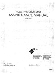
The <strong>BiPAP</strong> <strong>Vision</strong> Ventilatory Support System (<strong>BiPAP</strong> <strong>Vision</strong>), shown in Figure 1-1, is a microprocessor-controlled,<br />
positive pressure ventilatory assist system. The <strong>BiPAP</strong> <strong>Vision</strong> incorporates a user interface with multifunction<br />
keys, real time graphic displays, and integral patient and system alarms.<br />
The <strong>BiPAP</strong> <strong>Vision</strong> features a centrifugal blower to generate airflow, as well as hardware and software platforms<br />
that can be upgraded with an oxygen module and additional patient alarms. The system operates in the Continuous<br />
Positive Airway Pressure (CPAP), Pressure Support (S/T), and optional Proportional Assist Ventilation/Timed<br />
(PAV/T) modes.<br />
The <strong>BiPAP</strong> <strong>Vision</strong> contains a variety of integrated safety and self-diagnostic features. All system functions are<br />
checked at start-up and during operation. Errors are reported by visual and/or audible indicators.<br />
Pressure regulation is achieved by monitoring proximal airway pressure and adjusting flows accordingly to<br />
ensure that the proximal pressure equals the set pressure.<br />
1045049<br />
Rate<br />
12<br />
BPM<br />
EPAP<br />
6<br />
cm H 2O<br />
IPAP<br />
15<br />
cm H 2O<br />
Vol (ml)<br />
Flow (L/min)<br />
MODE: S/T MONITORING<br />
P (cm H 2 O)<br />
Options<br />
VT 1000 ml PIP 15 cm H2O MinVent 14 L/min<br />
PS = 9 cm H2O<br />
%O2<br />
55<br />
%<br />
Figure 1-1<br />
The <strong>BiPAP</strong> <strong>Vision</strong> Ventilator<br />
<strong>BiPAP</strong> <strong>Vision</strong> <strong>Service</strong> <strong>Manual</strong>
1.2 <strong>Service</strong> Notice<br />
This service manual was prepared by <strong>Respironics</strong> primarily for use by qualified technicians<br />
required to service the <strong>BiPAP</strong> <strong>Vision</strong>.<br />
1.3 Technical Support<br />
<strong>BiPAP</strong> <strong>Vision</strong> <strong>Service</strong> <strong>Manual</strong><br />
Chapter 1: Introduction 1-3<br />
<strong>Respironics</strong> is committed to customer satisfaction, and may be contacted with any questions or for technical<br />
support at the following numbers:<br />
U.S. and Canada<br />
International<br />
Phone: 1-800-345-6443<br />
Fax: 1-800-866-0245<br />
Phone: 1-724-387-4000<br />
Fax: 1-724-387-5012<br />
E-Mail service@respironics.com<br />
Visit <strong>Respironics</strong> Home Page on the World Wide Web at:<br />
http://www.respironics.com<br />
1045049<br />
Chp. 1
Chapter 2: Warnings, Cautions, and Notes 2-1<br />
Chapter 2: Warnings, Cautions, and<br />
Notes<br />
2.1 Warnings ........................................................................................ 2-2<br />
2.2 Cautions ......................................................................................... 2-3<br />
2.3 Notes .............................................................................................. 2-4<br />
<strong>BiPAP</strong> <strong>Vision</strong> <strong>Service</strong> <strong>Manual</strong><br />
1045049
2-2<br />
Chapter 2: Warnings, Cautions, and Notes<br />
Chapter 2: Warnings, Cautions, and Notes<br />
WARNING: Indicates the possibility of injury.<br />
CAUTION: Indicates the possibility of damage to the device.<br />
NOTE: Places emphasis on an operating or procedural characteristic.<br />
2.1 WARNINGS<br />
2.1.1 Safety<br />
1045049<br />
• Do not use the <strong>BiPAP</strong> <strong>Vision</strong> in the presence of a flammable anesthetic mixture with<br />
air, oxygen, or nitrous oxide.<br />
Oxygen supports combustion. Do not use oxygen while smoking or in the presence of<br />
an open flame.<br />
When using the optional oxygen module, the <strong>BiPAP</strong> <strong>Vision</strong> does not provide an oxygen<br />
sensor to monitor oxygen concentrations delivered to the patient circuit. Therefore, the<br />
use of oxygen with the <strong>BiPAP</strong> <strong>Vision</strong> should be monitored through oximetry.<br />
NOTE: Refer to the Clinical <strong>Manual</strong> for guidelines on Applications and Operation.<br />
2.1.2 Operational<br />
If the “Ventilator Inoperable” indicator illuminates, refer to Chapter 6 of this manual for<br />
troubleshooting guidelines.<br />
Never attach oxygen tubing or any positive pressure source to the pressure port on the<br />
front panel of the <strong>BiPAP</strong> <strong>Vision</strong>.<br />
<strong>BiPAP</strong> <strong>Vision</strong> <strong>Service</strong> <strong>Manual</strong>
Warnings (Continued)<br />
2.1.3 <strong>Service</strong><br />
Chapter 2: Warnings, Cautions, and Notes 2-3<br />
CAUTION: Electronic components used in this device are subject to damage from static<br />
electricity. Repairs made to this device must be performed only in an antistatic,<br />
ESD-protected environment.<br />
2.1.4 Cleaning<br />
2.2 CAUTIONS<br />
Do not attempt to make connection to the diagnostic RS232 connector on the back panel of<br />
the <strong>BiPAP</strong> <strong>Vision</strong> to obtain repair information while the unit is operating on a patient.<br />
To assure the safety of the service technician and specified performance of the device,<br />
<strong>Respironics</strong> recommends that only qualified technicians perform repairs to the <strong>BiPAP</strong><br />
<strong>Vision</strong>. Contact <strong>Respironics</strong> Technical <strong>Service</strong> for service training and authorization<br />
information.<br />
High voltages are present inside this device. To avoid electrical shock, disconnect the<br />
electrical supply before attempting any repairs on the device.<br />
For continued protection against risk of fire, replace fuses with those of the same type<br />
and rating only.<br />
To avoid electrical shock, unplug the <strong>BiPAP</strong> <strong>Vision</strong> unit before cleaning it.<br />
While cleaning the unit, do not allow any liquid to enter the cabinet or the inlet filter.<br />
Care should be taken to avoid exposing the <strong>BiPAP</strong> <strong>Vision</strong> to operating, storage, and<br />
transport temperatures near the extremes specified in Chapter 4. If exposed to such<br />
temperatures, allow the unit to cool or warm to room temperature before turning it on.<br />
The unit must be positioned on its base for proper operation.<br />
Always use an inlet filter when the <strong>BiPAP</strong> <strong>Vision</strong> is in use.<br />
If using the oxygen module, do not exceed 100 psig oxygen supply pressure.<br />
<strong>BiPAP</strong> <strong>Vision</strong> <strong>Service</strong> <strong>Manual</strong><br />
1045049
2-4<br />
Chapter 2: Warnings, Cautions, and Notes<br />
2.3 NOTES<br />
1045049<br />
This device contains a rechargeable nickel-cadmium (NiCAD) battery which is used by<br />
the alarms in the event of a power failure.<br />
• Refer to the <strong>BiPAP</strong> <strong>Vision</strong> Clinical <strong>Manual</strong> for a complete list of operational Warnings,<br />
Cautions, and Notes.<br />
Additional WARNINGS, CAUTIONS, and NOTES are located throughout this manual.<br />
<strong>BiPAP</strong> <strong>Vision</strong> <strong>Service</strong> <strong>Manual</strong>
Chapter 3: Description and Theory of Operation<br />
Chapter 3: Description and Theory of<br />
Operation<br />
3.1 <strong>BiPAP</strong> <strong>Vision</strong> Ventilatory Support System ............................... 3-2<br />
3.2 Power Supply Subsystem (PSS) ................................................ 3-6<br />
3.3 Main Control (MC)...................................................................... 3-8<br />
3.4 Pressure Control (PC) ................................................................. 3-9<br />
3.5 Display Control (DC) ................................................................ 3-11<br />
3.6 Airflow Module (AFM) ............................................................ 3-14<br />
3.7 Oxygen Module (OM) .............................................................. 3-16<br />
3.8 Description of Ventilator Modes ............................................. 3-17<br />
3.9 Nurse Call / Remote Alarm .................................................... 3-19<br />
3.10 Patient Disconnect Alarm ........................................................ 3-21<br />
<strong>BiPAP</strong> <strong>Vision</strong> <strong>Service</strong> <strong>Manual</strong><br />
1045049<br />
3-1
3-2<br />
Chapter 3: Description and Theory of Operation<br />
Chapter 3: Description and Theory of Operation<br />
3.1 <strong>BiPAP</strong> <strong>Vision</strong> Ventilatory Support System<br />
The <strong>BiPAP</strong> <strong>Vision</strong> is a microprocessor-controlled, positive pressure ventilatory assist system. The<br />
system’s integral air intake filter draws in ambient air which is then pressurized by the system’s centrifugal<br />
blower assembly. The In-Line Flow Restrictor (ILFR) valve and Pressure Regulation Valve (PRV),<br />
which are both located in the blower discharge airway, regulate total flow and pressure at the blower<br />
discharge system. An oxygen module can be installed to add a controlled source of supplemental oxygen,<br />
up to 100%, to the patient.<br />
The Pressure Control (PC) board continuously monitors the readings from the Airflow Module (AFM) of<br />
total gas flow, temperature, generated pressure, and patient circuit pressure to ensure prescribed therapy<br />
to the patient. The PC board transmits process data to the Main Control (MC) board which then provides<br />
overall control of the <strong>BiPAP</strong> <strong>Vision</strong>, including conveying instructions to the PC board regarding required<br />
valve stem position and blower speed.<br />
The unique design and operation of the ventilator makes it especially suited for mask applications.<br />
Designed with the <strong>BiPAP</strong> Auto-Trak Sensitivity TM feature that automatically adjusts to changing circuit<br />
conditions, the ventilator is capable of ensuring optimum patient-ventilator synchronicity despite changes<br />
in breathing patterns and circuit leaks. (Refer to the <strong>BiPAP</strong> <strong>Vision</strong> Clinical <strong>Manual</strong>.)<br />
A liquid crystal display (LCD) screen is mounted on the front enclosure of the <strong>BiPAP</strong> <strong>Vision</strong>. The LCD<br />
and the Display Control (DC) board provide the primary user interface with the ventilator, including the<br />
visual presentation of data, control features, and visual and audible presentation of alarm conditions. The<br />
user interacts with the ventilator through the touch pad and rotation of the rotary encoder while observing<br />
the results of this input on the display. The information provided on the display varies depending on<br />
the state of the ventilator and / or the operations being performed.<br />
The <strong>BiPAP</strong> <strong>Vision</strong> incorporates a number of safety features and self-diagnostic systems. System internal<br />
functions are checked automatically at start-up, and periodically throughout normal operation. An<br />
audible and visual alarm announces failures of principal subsystems. Integrated patient alarms are also<br />
provided and are announced on a visual message display area as well as with an audible tone.<br />
The following sections of this chapter describe in more detail the major subsystems and components that<br />
make up the <strong>BiPAP</strong> <strong>Vision</strong> and its basic theory of operation.<br />
1045049<br />
<strong>BiPAP</strong> <strong>Vision</strong> <strong>Service</strong> <strong>Manual</strong>
<strong>BiPAP</strong> <strong>Vision</strong> Ventilatory Support System (Continued)<br />
Subsystem<br />
Chapter 3: Description and Theory of Operation<br />
Function<br />
PSS The Power Supply Subsystem (PSS) provides DC power to the <strong>BiPAP</strong> <strong>Vision</strong><br />
from an AC source.<br />
MC The Main Control (MC) board or Main Control Subsystem (MCS) performs all control,<br />
or data acquisition, and calculations required for the user-selected parameters. In addition,<br />
MCS the MC performs the start-up test and reports all errors.<br />
PC The Pressure Control (PC) board or Pressure Airflow Subsystem (PAS) controls the blower<br />
or and valves to generate and regulate the system pressure. The PAS senses the outlet<br />
PAS pressure and the patient pressure and regulates the outlet pressure to the patient circuit.<br />
DC Through the touch pad, the Display Control (DC) board or Display/Control<br />
or Subsystem (D/CS) evaluates user inputs and passes valid parameters to the MC. The DC<br />
D/CS receives display data from the MC. The DC also has its own internal functions; the<br />
results of which are reported to the MC.<br />
AFM The Airflow Module (AFM), including the mass airflow sensor in the airstream,<br />
provides an airflow measurement interface to the PC, allowing the PC to<br />
measure total flow, temperature, and system pressure.<br />
ILFR The In-Line Flow Restrictor (ILFR) valve assembly regulates the total flow<br />
from the blower discharge.<br />
PRV The Pressure Regulation Valve (PRV) assembly is opened during exhalation to<br />
allow the patient flow to be exhausted.<br />
OM The Oxygen Module (OM) subassembly regulates and proportions the oxygen released<br />
into the air from the blower according to the oxygen concentration level set on the<br />
parameters screen.<br />
<strong>BiPAP</strong> <strong>Vision</strong> <strong>Service</strong> <strong>Manual</strong><br />
1045049<br />
3-3
3-4<br />
Chapter 3: Description and Theory of Operation<br />
<strong>BiPAP</strong> <strong>Vision</strong> Block Diagram<br />
1045049<br />
*<br />
*<br />
<strong>BiPAP</strong> <strong>Vision</strong> Ventilatory Support System (Continued)<br />
*<br />
*<br />
<strong>BiPAP</strong> <strong>Vision</strong> <strong>Service</strong> <strong>Manual</strong><br />
Figure 3-1<br />
<strong>BiPAP</strong> <strong>Vision</strong> Block Diagram<br />
* For S/N 106001 and greater
Pneumatics Block Diagram<br />
Chapter 3: Description and Theory of Operation<br />
<strong>BiPAP</strong> <strong>Vision</strong> <strong>Service</strong> <strong>Manual</strong><br />
1045049<br />
3-5
3-6<br />
Chapter 3: Description and Theory of Operation<br />
3.2 Power Supply Subsystem (PSS)<br />
The PSS supplies the Main Control (MC), Pressure Control (PC), and the Display Control (DC) with the<br />
proper DC supply voltage. Safety features designed into the circuitry include an overvoltage disconnect,<br />
low voltage supply detect, and line loss detect. Other features include “power-on” indicator voltage,<br />
circulation fan power, and an On/Off switch connection.<br />
1045049<br />
Figure 3-2<br />
PSS Block Diagram<br />
<strong>BiPAP</strong> <strong>Vision</strong> <strong>Service</strong> <strong>Manual</strong>
3.2.1 Input Range<br />
Chapter 3: Description and Theory of Operation<br />
The <strong>BiPAP</strong> <strong>Vision</strong> can operate with an AC input of 100, 120, 230, or 240 VAC (±10%) depending on the<br />
model.<br />
3.2.2 DC Supply<br />
The output DC supply is fused at 30 amps and delivers between 20.6 VDC and 35 VDC with a maximum<br />
ripple of 1 vpp (peak-to-peak voltage) to the MC, PC, and DC.<br />
3.2.3 Overvoltage Disconnect<br />
The overvoltage disconnect is used to remove the DC supply output when it exceeds 36 VDC and reconnects<br />
it when the level returns to an acceptable value.<br />
3.2.4 AC Fail<br />
The MC module monitors the level of DC supply voltage and the AC voltage output from the transformer<br />
supply winding to determine if an AC fail condition exists.<br />
Low DC supply detect – If the DC supply voltage drops to 19.38 VDC or lower (nominal), an AC fail<br />
condition will be triggered.<br />
Line loss detect – The AC voltage output from the transformer supply winding is monitored for a loss-ofcycle<br />
condition. Both legs of the winding are input to the monitoring circuitry. Whenever AC is lost, the<br />
AC fail signal is activated.<br />
3.2.5 Outputs<br />
The PSS module also includes the following:<br />
a. Front panel “power-on” indicator voltage (J5)<br />
b. Circulation fan power (J4)<br />
c. On / Off switch (part of J2)<br />
<strong>BiPAP</strong> <strong>Vision</strong> <strong>Service</strong> <strong>Manual</strong><br />
Power Supply Subsystem (PSS) (Continued)<br />
d. Circulation fan current sense information to (J12) on the PC subsystem.<br />
1045049<br />
3-7
3-8<br />
Chapter 3: Description and Theory of Operation<br />
3.3 Main Control Subsystem (MC)<br />
The MC is microcontroller-based and provides overall system control and supervision by monitoring the<br />
activity of all the other system modules and providing commands to these modules based on user and<br />
system input. The MC also acts as the bus controller for all subsystem communications using the<br />
Intermodule Communications Bus (ICB).<br />
1045049<br />
* For S/N units >106K<br />
Figure 3-3<br />
MC Block Diagram<br />
<strong>BiPAP</strong> <strong>Vision</strong> <strong>Service</strong> <strong>Manual</strong><br />
*<br />
J6<br />
Nurse Call /<br />
Remote Alarm * J5<br />
4<br />
DCS RX / TX<br />
PAS RX / TX
3.4 Pressure Control Subsystem (PC)<br />
The PC functions through a microcontroller to:<br />
a. Communicate with the Main Controller Subsystem (MC)<br />
b. Communicate to a terminal / PC for diagnostics<br />
Chapter 3: Description and Theory of Operation<br />
c. Acquire sensor data through an Analog-to-Digital Converters (ADC, A / D)<br />
d. Control valves and the blower motor through a Digital-to-Analog Converter (DAC)<br />
e. Respond to or invoke an error signal<br />
or *<br />
J15*<br />
*<br />
* For Units Serial Number
3-10<br />
Chapter 3: Description and Theory of Operation<br />
Pressure Control Subsystem (PC) (Continued)<br />
3.4.1 Microcontroller Interface<br />
Programmable Array Logic (PAL) memory device decodes the chip selects in such a way that the program<br />
code is retrieved from the EEPROM and data is retrieved from the RAM. An additional PAL<br />
provides the interface for the Intermodule Communications Bus (ICB). The microprocessor monitors:<br />
oxygen and gas temperatures; Airflow Module (AFM) and Oxygen Module (OM) detection; In-Line Flow<br />
Restrictor (ILFR), Pressure Regulation Valve (PRV), and oxygen valve DAC control voltage; blower DAC<br />
control voltage; and power supply and reference voltages.<br />
3.4.2 Blower Motor Drive<br />
The complete motor controller includes closed loop speed control via analog circuitry. When the desired<br />
speed and actual speed are known by the processor, the speed is adjusted by increasing or decreasing the<br />
DAC converter output to achieve proper pressure and flow.<br />
3.4.3 Pressure Regulation Valve (PRV) and In-Line Flow Restrictor<br />
(ILFR) Drives<br />
The valve drives have closed loop control via the microprocessor. The microprocessor reads seven<br />
pressure, flow, and temperature sensors through the PC hardware, and receives prescription parameters<br />
from the MC. The microprocessor then adjusts analog DAC voltages to control the PRV and ILFR valves<br />
as required to meet the prescription.<br />
3.4.4 Pressure Sensors<br />
The PC module has two dual pressure sensors (MT1 and MT2) and a single sensor (MT3). They measure<br />
patient pressure, unit outlet pressure, and barometric pressure. These sensors are subject to calibration<br />
with their calculated slope and intercept values stored in the on-board EEPROM. MT3 is a backup outlet<br />
pressure sensor that provides a redundant check of the primary outlet sensor located on the AFM.<br />
NOTE: Calibration is factory programmed and field adjustment is not required.<br />
3.4.5 Error Line Control (ELC) Circuit<br />
The ELC circuit is designed to simply detect a failure from, or signal a failure to, the MC and Display<br />
Control (DC) modules. If the ELC line activates, only a power On / Off of the ventilator can clear this<br />
latched circuit state.<br />
3.4.6 Diagnostics Connector<br />
The diagnostic connector (J3) interfaces with the microprocessor to view PC functions and system errors<br />
on units from serial number 100500 to 105999, unless upgraded. For units greater than this, the diagnostic<br />
connector is on the rear of the unit.<br />
1045049<br />
<strong>BiPAP</strong> <strong>Vision</strong> <strong>Service</strong> <strong>Manual</strong>
3.5 Display Control Subsystem (DC)<br />
Chapter 3: Description and Theory of Operation<br />
The DC provides a means of displaying the operating mode, measured and calculated operating parameters,<br />
parameter setpoints, alarm limits, real-time graphics, and general status information. The DC also<br />
provides the necessary user interface controls to modify the operating mode, parameter set points, alarm<br />
limits, and graphical scales; and to reset or silence the audible alarm, and freeze or unfreeze graphics.<br />
The displays and controls are described in more detail in the following subsections.<br />
*<br />
or<br />
* For Units Serial Number < 106K<br />
*<br />
Figure 3-5<br />
DC Block Diagram<br />
<strong>BiPAP</strong> <strong>Vision</strong> <strong>Service</strong> <strong>Manual</strong><br />
*<br />
or<br />
1045049<br />
3-11
3-12<br />
Chapter 3: Description and Theory of Operation<br />
Display Control (DC) (Continued)<br />
3.5.1 DC/DC Converter<br />
The DC/DC converter reduces the +24 VDC bulk supply to a +5 VDC logic level. (S/N
3.5.12 Error LED<br />
Chapter 3: Description and Theory of Operation<br />
The error LED indicates that an error condition was detected, and it illuminates to make unit diagnosis<br />
easier.<br />
3.5.13 Diagnostic Interface<br />
The diagnostic connector interface (J5) interfaces with the MCU to provide a means for the DC to download<br />
diagnostic data to a terminal or PC.<br />
3.5.14 EEPROM<br />
A serial EEPROM stores the setpoints for the backlighting and contrast and also for the appropriate<br />
diagnostic data.<br />
3.5.15 LCD Controller<br />
The DC circuit contains an LCD controller that interfaces with the display.<br />
3.5.16 Debouncing / Keypad Matrix<br />
The matrix keys are debounced and then the microprocessor scans the matrix to determine what key was<br />
depressed.<br />
3.5.17 Rotary Encoder Control<br />
The rotary encoder control circuit detects relative position, direction, and speed of the rotary encoder, all<br />
within one detent of movement.<br />
3.5.18 Audible Alarm Activation<br />
The audible alarm is activated by either an input from the ELC, the power fail circuitry, or the test alarm<br />
signal from the MCU. It will also occur when the wrong key has been depressed, an adjustable parameter<br />
has reached its limit, or the error signal has been activated.<br />
3.5.19 Audible Alarm Current Check<br />
An internal test is performed to verify the audible alarm current is acceptable.<br />
3.5.20 “Power-on“ in Safe State<br />
The DC contains circuitry that causes the hardware to “power-on” in a safe state; which is when the<br />
backlight is off, the display is off, and the Intermodule Communications Bus (ICB) is terminated. When<br />
the MCU determines that no Vent Inop error exists, it lets the unit resume operation under normal<br />
operating conditions.<br />
3.5.21 Watchdog and Low Voltage Reset<br />
<strong>BiPAP</strong> <strong>Vision</strong> <strong>Service</strong> <strong>Manual</strong><br />
Display / Control Subsystem (D / CS) (Continued)<br />
The watchdog function has to be periodically reset by the microprocessor if a time-out period has been<br />
exceeded. This function is designed to reset the processor if the software gets lost. When a low logic level<br />
is detected, the ELC will be activated resulting in a system shutdown.<br />
1045049<br />
3-13
3-14<br />
Chapter 3: Description and Theory of Operation<br />
3.6 Airflow Module (AFM)<br />
The AFM is a submodule of the Pressure Control (PC). The AFM receives power from the PC and provides<br />
the following analog signals to the PAS:<br />
1045049<br />
a. Gas flow indication<br />
b. Pressure indication<br />
c. Temperature indication<br />
To provide indications accurate enough for system requirements, the AFM must be calibrated. Calibration<br />
data is stored in a nonvolatile memory that is part of the AFM. The flow, pressure, and temperature<br />
indications are for the ventilator gas stream flowing through a “flow body” attached to the AFM circuit<br />
board.<br />
3.6.1 Flow Body<br />
The flow body, with laminar flow element, is added to the ventilator gas stream, creating a small pressure<br />
differential to short a fraction of the flow through the AFM sensor. Inlet, outlet, and pressure ports are<br />
part of the flow body for tubing attachment to the AFM electronic sensors. Also, a hole is molded into the<br />
flow body to position the temperature sensor. The body has molded feet for attaching it to the AFM<br />
circuit board assembly.<br />
And/Or Oxygen Supply<br />
Figure 3-6<br />
AFM Block Diagram<br />
<strong>BiPAP</strong> <strong>Vision</strong> <strong>Service</strong> <strong>Manual</strong>
Airflow Module (AFM) (Continued)<br />
3.6.2 Analog Reference<br />
Chapter 3: Description and Theory of Operation<br />
The PC provides the AFM with power in the form of +12 VDC, –12 VDC, analog ground, +5 VDC, and<br />
digital ground. An analog voltage reference supply is derived from the +12 VDC to power the pressure<br />
and flow sensors so their bridge outputs can be factory calibrated.<br />
3.6.3 Flow Indication<br />
Total gas flow indication is provided by MT1. It is then amplified by an instrumentation amplifier, lowpass<br />
filtered, and sent to the PC board for conversion.<br />
3.6.4 Pressure Indication<br />
MT2, a precision compensated pressure sensor, provides unit outlet pressure indication. The sensor is<br />
followed by a low-pass filter and a differential amplifier, and then sent to the PC board for conversion.<br />
3.6.5 Temperature Measurement<br />
The temperature is measured using a sensor inserted into a molded hole in the flow body. The <strong>BiPAP</strong><br />
<strong>Vision</strong> requires temperature indication to correct air density and detect an undesirable temperature rise in<br />
the patient circuit.<br />
3.6.6 Calibration<br />
A data acquisition system, operating on a personal computer, is the control platform for AFM calibration<br />
of temperature, pressure, and flow. Correction factors are derived and stored in the AFM module in an<br />
EEPROM, with calibration accomplished by balancing the flow transducer bridge with an EEPOT. The<br />
PAS uses temperature, pressure, and flow to correct for actual operating conditions. Once calibrated, the<br />
AFM is interchangeable with other AFM assemblies.<br />
NOTE: Calibration is factory programmed only.<br />
3.6.7 Module Detection<br />
The PC must know the AFM is connected, since it is required for normal operation of the ventilator. An<br />
extra line pulls a PC microcontroller line near zero volts. If the line is above two volts, the AFM is not<br />
connected, and the PC will transition to the error state.<br />
<strong>BiPAP</strong> <strong>Vision</strong> <strong>Service</strong> <strong>Manual</strong><br />
1045049<br />
3-15
3-16<br />
Chapter 3: Description and Theory of Operation<br />
3.7 Oxygen Module (OM)<br />
The OM is an optional submodule of the Pressure Control (PC). It receives power from the PC and<br />
provides an analog signal to the PC for oxygen flow indication. To provide indications accurate enough<br />
for system requirements, the OM must be calibrated. Calibration data is stored in a nonvolatile memory<br />
that is part of the OM. The flow indication is for the ventilator pure oxygen stream flowing through a flow<br />
body attached to the OM circuit board.<br />
1045049<br />
Figure 3-7<br />
OM Block Diagram<br />
<strong>BiPAP</strong> <strong>Vision</strong> <strong>Service</strong> <strong>Manual</strong><br />
PC
3.8 Description of Ventilator Modes<br />
Chapter 3: Description and Theory of Operation<br />
The <strong>BiPAP</strong> <strong>Vision</strong> comes standard with two operating modes: Continuous Positive Airway Pressure<br />
(CPAP) and Spontaneous/Timed (S/T). A third, optional, Proportional Assist Ventilation/Timed (PAV/<br />
T) is also available.<br />
3.8.1 Continuous Positive Airway Pressure (CPAP)<br />
CPAP provides a constant pressure level delivered over the complete range of the patient’s spontaneous<br />
breathing cycle. Pressure is controlled and maintained. Flow is available to meet changing patient<br />
demands and automatically compensate for leaks. The mode delivers the prescribed level of pressure<br />
that has been set with the CPAP control (Range: 4 to 20 cm H 2 O).<br />
3.8.2 Spontaneous/Timed (S/T)<br />
The S/T mode provides either pressure support during spontaneous breaths or time-triggered, pressurelimited,<br />
time-cycled machine breaths.<br />
Spontaneous Breaths<br />
Two pressure levels are set: an EPAP level (range 4 to 20 cm H 2 O) to establish a baseline pressure and an<br />
IPAP level (range 4 to 40 cm H 2 O) that determines the amount of pressure support delivered with each<br />
breath (PS = IPAP– EPAP). During the inspiratory phase, the <strong>BiPAP</strong> <strong>Vision</strong> responds as necessary to<br />
satisfy the patient’s flow requirements while maintaining the preset IPAP pressure. Under these conditions,<br />
the patient is active in determining inspiratory time and tidal volume. The delivered tidal volume<br />
will be dependent upon the pressure differential between the IPAP and EPAP levels, patient effort, and<br />
the combined resistance and compliance of the circuit and the patient. If the patient does not actively<br />
participate, the <strong>BiPAP</strong> <strong>Vision</strong> responds appropriately.<br />
Timed Breaths<br />
The S/T mode can also provide a time-triggered, pressure-limited, time-cycled machine breath, when the<br />
spontaneous respiratory rate drops below the Rate control setting. If the ventilator does not detect a<br />
spontaneous trigger within the interval determined by the Rate control setting, it will activate a timetriggered<br />
machine breath and deliver the IPAP level. Machine breaths are not synchronized with patient<br />
effort, and once triggered to IPAP, the balance of the cycle is determined by the Timed Insp. Control<br />
setting. A maximum Timed Inspiratory setting of 3.0 seconds can be set, as long as the I:E Ratio does not<br />
exceed 1:1, as determined by the Rate setting. For example, see Figure 3-12. If the Rate control is set at 10<br />
BPM, the total respiratory cycle is six seconds. If a spontaneous trigger occurs before the six-second cycle<br />
time has elapsed, a spontaneously-triggered, pressure support breath occurs, a timed trigger will not<br />
occur, and the timer is reset for a new six second interval. If a six second interval passes without a<br />
spontaneous trigger, a timed trigger will be initiated and IPAP will be delivered for the duration of time<br />
set by the Timed Inspiration setting.<br />
<strong>BiPAP</strong> <strong>Vision</strong> <strong>Service</strong> <strong>Manual</strong><br />
1045049<br />
3-17
3-18<br />
Chapter 3: Description and Theory of Operation<br />
Description of Ventilator Modes (Continued)<br />
1045049<br />
Figure 3-12<br />
Timed Breath Example<br />
3.8.3 Proportional Assist Ventilation / Timed Mode (PAV/T)<br />
For a detailed description of functioning of the Proportional Assist Ventilation/Timed (PAV/T) Mode,<br />
refer to the appropriate <strong>BiPAP</strong> <strong>Vision</strong> Clinical manual. This mode utilizes the design features of S/T<br />
mode and is a software enhancement only.<br />
<strong>BiPAP</strong> <strong>Vision</strong> <strong>Service</strong> <strong>Manual</strong>
Chapter 3: Description and Theory of Operation<br />
3.9 Nurse Call/Remote Alarm Feature Operation (for s/n units<br />
greater than 106000 only)<br />
The unit will activate a remote signal for system shutdowns, patient alarms, and Loss of AC Power conditions<br />
which inhibit therapy. Note that a Check Vent condition does not activate the nurse call signal. The<br />
nurse call signal can be silenced via the Alarm Silence key for the same amount of time that the audible<br />
alarm on the <strong>Vision</strong> is silenced (two minutes). The signal can also be cleared by selection of the Alarm<br />
Reset key. The nurse call signal will automatically terminate when a patient alarm self-cancels.<br />
The Nurse Call/Remote Alarm feature is meant to be a backup with the main <strong>Vision</strong> alarm system being<br />
the primary alarm/alert mechanism.<br />
The Nurse Call or Remote Alarm signal is generated on the MC board and then can be connected to a<br />
hospital nursing station. This signal is opto-isolated and used to switch a relay to provide open or closed<br />
contacts to the remote station circuit. The arrangement of the two jumpers (JP1 and JP2) on the MC determine<br />
the output configuration that is utilized by a common connector on the rear panel of the <strong>Vision</strong>.<br />
The Nurse Call Adapter (RI P/N 1014280) along with the Nurse Call Cable (RI P/N 1003742) can be used<br />
to connect the <strong>Vision</strong> to a Nurse Call station.<br />
The jumper configuration on the MC circuit board can be selected to meet requirements according to the<br />
following table. Refer to the photo for jumper location.<br />
Option JP1 JP2 No Alarm Output Alarm Option System Requiring<br />
1 2,3 2,3 51.1K Open <strong>Respironics</strong> Remote Alarm<br />
2 2,3 1,2 Closed Open Central Alarm System<br />
3 1,2 1,2 Open Closed Central Alarm System<br />
NOTE: Option 2 is the original factory set configuration for S/N 106001 to 106368.<br />
Option 3 is the original factory set configuration for S/N 106369 and greater.<br />
JP 2<br />
<strong>BiPAP</strong> <strong>Vision</strong> <strong>Service</strong> <strong>Manual</strong><br />
JP1<br />
1045049<br />
3-19
3-20<br />
Chapter 3: Description and Theory of Operation<br />
Nurse Call / Remote Alarm (Continued)<br />
Details of option selections:<br />
Option 1:<br />
For use with <strong>Respironics</strong> Remote Alarm ( RI p/n 34003, or equivalent).<br />
Option 2:<br />
For use with alarm systems requiring NORMALLY OPEN contacts for an “alarm” condition and CLOSED contacts<br />
for a “no alarm” condition.<br />
Option 3:<br />
For use with alarm systems requiring NORMALLY CLOSED contacts for an “alarm” condition and OPEN contacts<br />
for a “no alarm” condition.<br />
Caution: The <strong>Vision</strong> Nurse Call/Remote Alarm port shall be connected to nurse call systems that meet the relevant<br />
local safety standards. Secondly, the nurse call port shall be connected to a low voltage circuit (less or<br />
equal to 42.4V peak ac or 50V dc). The leakage currents from the low voltage circuit shall not cause the<br />
<strong>Vision</strong> leakage currents to exceed acceptable levels. Lastly, the rated output current of the low voltage<br />
circuit shall not exceed 1A.<br />
1045049<br />
<strong>BiPAP</strong> <strong>Vision</strong> <strong>Service</strong> <strong>Manual</strong>
Chapter 3: Description and Theory of Operation<br />
3.10 <strong>BiPAP</strong> <strong>Vision</strong> Patient Disconnect Alarm Description of<br />
Operation<br />
The patient disconnect alarm (“Disconnect”) is based on the flow limit control algorithm in the <strong>Vision</strong>. The mitigation<br />
for the Disconnect alarm is to put the unit into flow limit control. This same action is done when the user selects<br />
the Standby key.<br />
3.10.1 Detection<br />
The unit determines that a patient is not connected to the circuit anymore based on flow for the given pressure. This<br />
is implemented via a look-up table, with a flow entry for every generated pressure. The range of flows is 95 to 180<br />
LPM, with 180 LPM being the low limit for any pressure above 9 cmH 2 O. If the unit detects flow greater than the<br />
threshold at any given pressure for more than 10 seconds (3 seconds in for software earlier than 13.2), the unit puts<br />
itself into the Flow Limit Control state. In this state, the unit attempts to limit the flow coming out of the mask in<br />
order to make putting the mask back on the patient easier and more comfortable for the patient.<br />
Also, for safety concerns, the oxygen valve closes to discontinue oxygen delivery during this condition.<br />
When the Standby key is selected by the user, the unit automatically enters the FLC state, regardless of the flow at<br />
the time the Standby key is selected.<br />
In order to limit the flow, the unit drops the pressure to 4 cmH 2 O. The algorithm was enhanced to work with the Full<br />
Face Mask a while ago. The Full Face Mask has a flap that will close the patient circuit and open the mask to<br />
atmosphere upon loss of flow and pressure. This flap must be kept in a position during FLC so that the patient<br />
circuit is not occluded. This allows the unit to detect when the patient is reconnected. The enhancement to the<br />
algorithm consists of the pressure being slowly increased to keep the flow at 160-170 LPM. The pressure level is<br />
limited to 10 cmH 2 O for software 11.2 and 11.3 (15 cmH 2 O for software 11.3a and higher), regardless of how much<br />
flow is being generated. Therefore, the unit will either output 160-170 LPM at some pressure or will be limited to<br />
some lesser flow at 10 cmH 2 O for software 11.2 and 11.3 (15 cmH 2 O for software 11.3a and higher).<br />
3.10.2 Termination<br />
There are two termination stages to FLC. During the first stage, as the pressure is being increased from 4 cmH 2 O to<br />
its maximum of 10 cmH 2 O for software 11.2 and 11.3 (15 cmH 2 O for software 11.3a and higher), FLC will be<br />
automatically terminated if the unit detects negative flow (i.e., the patient breaths back into the unit). This pressure<br />
increase takes about 10 – 12 seconds for software versions earlier than 13.2, depending on how soon the flow set<br />
point is reached. There have been two enhancements in software version 13.2 in this area. The first is that the<br />
pressure is increased faster (1 cmH 2 O per 40 ms instead of the previous ¼ cmH 2 O per 40 ms) to shorten the amount<br />
of time in stage one. The second change concerns the flow range processing. In software versions earlier than 13.2,<br />
when the pressure is dropped to 4 cmH 2 O and the flow is greater than the desired flow range (160-170 LPM), the<br />
flow limit algorithm attempts to decrement the pressure to get the flow into that desired range. In software version<br />
13.2, that was changed to immediately enter stage 2 under that condition.<br />
<strong>BiPAP</strong> <strong>Vision</strong> <strong>Service</strong> <strong>Manual</strong><br />
1045049<br />
3-21
3-22<br />
Chapter 3: Description and Theory of Operation<br />
Once either the flow set point or the maximum pressure is reached, the unit will automatically terminate<br />
FLC for either the detection of negative flow or if flow varies from the current flow by more than 40 LPM<br />
in software versions prior to 13.2 and 20 LPM for software version 13.2. For instance, if the 160-170 LPM<br />
set point has been reached, the unit will terminate FLC if the flow drops below 120 LPM or goes above<br />
210 LPM in older software and 140-190 LPM in the new software.<br />
If the flow set point has not been reached, the current flow at 10 cmH2O for software 11.3 and 11.3 (15<br />
cmH 2 O for software 11.3a and higher) is used as the set point. For instance, if only 80 LPM can be<br />
reached at 10 cmH 2 O for software 11.3 and 11.3 (15 cmH 2 O for software 11.3a and higher), the thresholds<br />
for automatic termination of FLC will be 40 LPM and 120 LPM in older software and 60-100 LPM in new<br />
software.<br />
This allows FLC to be terminated without the patient necessarily breathing back into the machine but by<br />
the simple act of refitting the mask to the patient.<br />
The Standby condition, besides being terminated automatically by the above methods, can also be<br />
manually terminated by reselecting the highlighted Standby soft key on the Monitoring screen.<br />
When FLC is terminated during a “Disconnect” alarm period, the alarm is self-cancelled. That means<br />
that the audible component of the alarm is silenced but the visual component of the alarm remains<br />
displayed on the screen. That can be cleared by selecting the Alarm Reset key.<br />
1045049<br />
Note: During FLC, the oxygen parameter setting reduces to 21%, regardless of the setting.<br />
<strong>BiPAP</strong> <strong>Vision</strong> <strong>Service</strong> <strong>Manual</strong>
Chapter 4: Specifications and<br />
Control Ranges<br />
Chapter 4: Specifications and Control Ranges 4-1<br />
4.1 Specifications ............................................................................... 4-2<br />
4.2 Control Ranges and Increments .............................................. 4-5<br />
<strong>BiPAP</strong> <strong>Vision</strong> <strong>Service</strong> <strong>Manual</strong><br />
1045049
4-2<br />
Chapter 4: Specifications and Control Ranges<br />
Chapter 4: Specifications and Control Ranges<br />
4.1 Specifications<br />
ENVIRONMENTAL:<br />
Temperature ....................................... Operating: 40° F to 104° F (4.4° C to 40° C)<br />
Transport / Storage: –4° F to 140°F (–20 o C to 60 o C)<br />
Humidity ............................................ Storage and Operating: 0 to 95% Relative Humidity<br />
PHYSICAL:<br />
Dimensions ........................................ At the base: 16" (L) × 14 3 /8" (W) × 10 5 /8" (H)<br />
(40.6 cm x 36.5 cm x 27cm)<br />
Weight ................................................ 34 lbs (15.4 kg)<br />
ELECTRICAL:<br />
AC Input Voltage (VAC) ................. 100/120/230/ 240 VAC<br />
Single Phase<br />
±10%<br />
Fuses ................................................... 100 – 120 VAC ~ T 3.5 A, 5 × 20 mm, Time Lag (×2)<br />
(For serial no.’s 100500 and higher –<br />
<strong>Respironics</strong> Reorder # 1000749)<br />
Power Consumption ........................ 300 VA max.<br />
AC Current ........................................ 3.0 A maximum<br />
AC Frequency.................................... 50/60 Hz<br />
1045049<br />
115 VAC ~ T 3.0 A, 250 V, ¼” × 1¼”<br />
(For serial no.’s 100499 and lower –<br />
<strong>Respironics</strong> Recorder # 582100)<br />
220 VAC, 230 VAC and 240 VAC ~ T 1.6 A, 250 V, 5 × 20 mm<br />
(For all serial no.’s – <strong>Respironics</strong> Recorder # 1000750)<br />
Class ................................................... Protection Against Electrical Shock: Class I<br />
<strong>BiPAP</strong> <strong>Vision</strong> <strong>Service</strong> <strong>Manual</strong>
Specifications (Continued)<br />
Chapter 4: Specifications and Control Ranges 4-3<br />
Type .................................................... BF<br />
Degree of Protection Against Harmful Ingress of Water:<br />
Ordinary Equipment, IPX0<br />
Electromagnetic<br />
Compatibility ..................................... The <strong>BiPAP</strong> <strong>Vision</strong> meets the requirements of IEC 601-1-2<br />
Earth Resistance ................................ Less than 0.10 ohms<br />
Earth Leakage Current ......................<br />
Normal Pole, No Earth, L2 ........ Less than 300 µA<br />
Reverse Pole, No Earth, L2 ........ Less than 300 µA<br />
Reverse Pole, No Earth, No L2.. Less than 1000 µA<br />
Normal Pole, No Earth, No L2 .. Less than 1000 µA<br />
Insulation Resistance ........................ Greater than 2 megaohms<br />
Noise Level ......................................... No specification is given because various test instruments, test<br />
procedures, and unit operating conditions produce varying<br />
results.<br />
Alarm Sound Level ........................... Between 70 and 85 dBA peak at a distance of 1 meter.<br />
PRESSURE:<br />
Output ................................................. 4 to 40 cm H 2 O<br />
Dynamic Regulation .......................... ± 2 cm H 2 O at sinusoidal flow @ ± 100 L/min<br />
<strong>Static</strong> Regulation ................................ ± 2 cm H 2 O from –60 to 120 L/min<br />
Elevation.............................................. 0 to 5000 ft above sea level<br />
CONTROL ACCURACY:<br />
Timed Inspiration .............................. ± 0.2 sec of the set point<br />
Rate ...................................................... ± 1 BPM of the set point<br />
Oxygen Concentration ....................... The greater of ± 3% or ±10% of the set point<br />
DISPLAY ACCURACY:<br />
Pressure ............................................... ± 1 cm H 2 O<br />
Volume ................................................ ± 10% (during stable conditions)<br />
Flow ..................................................... ± 10% (during stable conditions)<br />
<strong>BiPAP</strong> <strong>Vision</strong> <strong>Service</strong> <strong>Manual</strong><br />
1045049
4-4<br />
Chapter 4: Specifications and Control Ranges<br />
Specifications (Continued)<br />
TRIGGER SENSITIVITY:<br />
(Refer to <strong>BiPAP</strong> <strong>Vision</strong> Clinical <strong>Manual</strong> Auto-Trak section for more details)<br />
Spontaneous Trigger ......................... Shape Trigger<br />
Volume 6 cc above<br />
Spontaneous Cycle ............................ Spontaneous Expiratory Threshold (SET)<br />
Shape Cycle<br />
IPAP maximum of 3.0 sec<br />
Flow Reversal<br />
OXYGEN MODULE INLET:<br />
Pressure Range .................................. 50 to 100 psig<br />
Inlet Fitting ......................................... DISS male oxygen connector<br />
INTERNAL BATTERIES:<br />
Alarm Battery ..................................... NiCAD<br />
Location: D/C<br />
3.6 VDC, 110 mAh<br />
Rechargeable (See Section 5.9.3 for details)<br />
(RI P/N 1012819)<br />
Data Retention Battery Type: Lithium Cell<br />
(for original MCS board)<br />
Location: MCS<br />
+3 VDC, 300 mAh<br />
Not Rechargeable<br />
(RI P/N 1001988)<br />
Data Retention Battery Type: Lithium Cell<br />
(for current MC Board ) Location: MCS<br />
+3 VDC, 300 mAh<br />
Not Rechargeable<br />
(RI P/N 1006005)<br />
1045049<br />
V leak<br />
<strong>BiPAP</strong> <strong>Vision</strong> <strong>Service</strong> <strong>Manual</strong>
4.2 Control Ranges and Increments<br />
Chapter 4: Specifications and Control Ranges 4-5<br />
NOTE: Refer to the applicable <strong>BiPAP</strong> <strong>Vision</strong> Clinical <strong>Manual</strong> for PAV/T information.<br />
4.2.1 Parameters<br />
*With optional Oxygen Module<br />
4.2.2 Alarms (Adjustable)<br />
Alarm Control Control<br />
Range Increments<br />
High Pressure 5 to 50 cm H 2 0 1 cm H 2 0<br />
Low Pressure Disabled to 40 cm H 2 0 1 cm H 2 0<br />
Low Pressure Delay 0 to 60 sec. 1 cm H 2 0<br />
*With optional Alarm Module<br />
Apnea Disabled; 20 to 40 sec. 4 set points;<br />
Disabled, 20, 30, 40 sec.<br />
Low Minute Disabled to 99 L/min. 1 L/min.<br />
Ventilation*<br />
High Rate* 4 to 120 BPM 1 BPM<br />
Low Rate* 4 to 120 BPM 1 BPM<br />
<strong>BiPAP</strong> <strong>Vision</strong> <strong>Service</strong> <strong>Manual</strong><br />
1045049
4-6<br />
Chapter 4: Specifications and Control Ranges<br />
Control Ranges and Increments (Continued)<br />
4.2.3 Display Ranges & Increments<br />
1045049<br />
PARAMETER DISPLAY DISPLAY<br />
RANGE RESOLUTION<br />
IPAP 0 TO 50 CM H 2 O 1 CM H 2 O<br />
EPAP 0 TO 50 CM H 2 O 1 CM H 2 O<br />
CPAP 0 TO 50 CM H 2 O 1 CM H 2 O<br />
RATE 0 TO 150 BPM 1 BPM<br />
EXHALED TIDAL 0 TO 4000 ML 1 ML<br />
VOLUME (VT)<br />
MINUTE VENTILATION 0 TO 99 L /MIN 1 L / MIN<br />
(MIN VENT)<br />
TOTAL LEAK (TOT LEAK) 0 TO 300 L/MIN 1 L / MIN<br />
PATIENT LEAK 0 TO 300 L /MIN 1 L /MIN<br />
(PT. LEAK)<br />
PEAK INSPIRATORY 0 TO 50 CM H 2 O 1 CM H 2 O<br />
PRESSURE (PIP)<br />
PERCENT OF PATIENT 0 TO 100% 1%<br />
TRIGGERED BREATHS<br />
(PT.TRIG)<br />
TI/TTOT 0 TO 100% 1%<br />
<strong>BiPAP</strong> <strong>Vision</strong> <strong>Service</strong> <strong>Manual</strong>
Chapter 5: Routine Maintenance<br />
<strong>BiPAP</strong> <strong>Vision</strong> <strong>Service</strong> <strong>Manual</strong><br />
Chapter 5: Routine Maintenance 5-1<br />
5.1 Cleaning the <strong>BiPAP</strong> <strong>Vision</strong> ....................................................... 5-2<br />
5.2 Replacing the Inlet Filter........................................................... 5-3<br />
5.3 Cleaning / Replacing the Nylon Mesh Inlet Filter .............. 5-4<br />
5.4 Replacing the Oxygen Regulator Filter ................................. 5-6<br />
5.5 Changing the System Fuses...................................................... 5-8<br />
5.6 Voltage Selection ....................................................................... 5-10<br />
5.7 Power Cord Inspection ............................................................5-10<br />
5.8 Internal Alarm Battery ............................................................ 5-11<br />
5.9 Preventive Maintenance Schedule ........................................5-14<br />
1045049
5-2<br />
Chapter 5: Routine Maintenance<br />
5.1 Cleaning the <strong>BiPAP</strong> <strong>Vision</strong><br />
CAUTION: Do not immerse the <strong>BiPAP</strong> <strong>Vision</strong> in water or allow any liquid to enter the cabinet or<br />
the inlet filter.<br />
NOTE: The following guidelines for cleaning refer to the <strong>BiPAP</strong> <strong>Vision</strong> only. Refer to the<br />
individual instructions for cleaning accessories.<br />
5.1.1 Cleaning the Front Panel<br />
Clean the front panel as needed by wiping with water or 70% isopropyl alcohol only.<br />
5.1.2 Cleaning the Enclosure<br />
Clean the exterior of the enclosure as needed by wiping with any anti-bacterial agent.<br />
CAUTION: Do not allow any liquid to enter the cabinet or the inlet filter.<br />
NOTE: Do not clean the Auto-Trak sticker with anything except mild soap and water.<br />
1045049<br />
<strong>BiPAP</strong> <strong>Vision</strong> <strong>Service</strong> <strong>Manual</strong>
5.2 Replacing the Inlet Filter<br />
<strong>BiPAP</strong> <strong>Vision</strong> <strong>Service</strong> <strong>Manual</strong><br />
Chapter 5: Routine Maintenance 5-3<br />
CAUTION: A dirty inlet filter may cause high operating temperatures, and may affect ventilator<br />
performance. Examine the inlet filter for integrity and cleanliness before each use, and<br />
as required during operation.<br />
Step 1 Turn the <strong>BiPAP</strong> <strong>Vision</strong> OFF and unplug the electrical cord from the wall outlet and from the<br />
back of the unit.<br />
Removing the Filter<br />
Step 2 Remove the inlet filter cap by pinching the latch, then rotate the cap until the hinge is<br />
free from its slot.<br />
NOTE: The inlet filter is disposable. Do not attempt to clean the inlet filter. When the filter is<br />
dirty replace it with a new filter. Use only <strong>Respironics</strong> filters; see Chapter 7 for<br />
the filter reorder number.<br />
(P/N 582101 x6)<br />
Installing the Filter<br />
Figure 5-1<br />
Removing the Filter Cap<br />
(P/N 1003444)<br />
Step 3 Place the filter inside the cap, then reverse Step 2 to reinstall the filter cap.<br />
NOTE: To clean any of the accessories, refer to each accessory’s instruction sheet.<br />
1045049
5-4<br />
Chapter 5: Routine Maintenance<br />
5.3 Cleaning/Replacing the Nylon Mesh Inlet Filter<br />
CAUTION: A dirty nylon mesh inlet filter may cause high operating temperatures<br />
and may affect ventilator performance.<br />
Step 1 Turn the <strong>BiPAP</strong> <strong>Vision</strong> off and unplug the electrical cord from the wall outlet and<br />
from the back of the unit.<br />
Step 2 Remove the filter cap and inlet filter. (See Section 5.2 for more detailed instructions on<br />
removing the filter cap and inlet filter.)<br />
Step 3 Using a medium Phillips screwdriver, remove the two screws that secure the nylon mesh<br />
inlet filter to the filter enclosure. Remove the nylon mesh inlet filter.<br />
1045049<br />
Figure 5-2<br />
Removing the Nylon Mesh Filter<br />
NOTE: Depending on the condition of the nylon mesh inlet filter, it may be cleaned and<br />
reused. If the filter is in good shape, follow the cleaning instructions in Step 4. If the<br />
filter must be replaced, proceed to Step 5.<br />
NOTE: If the nylon mesh inlet filter is to be cleaned, care should be taken to protect the<br />
adhesive on the edges of the filter. If the adhesive is damaged, the filter may not<br />
correctly seal when reinstalled.<br />
<strong>BiPAP</strong> <strong>Vision</strong> <strong>Service</strong> <strong>Manual</strong>
<strong>BiPAP</strong> <strong>Vision</strong> <strong>Service</strong> <strong>Manual</strong><br />
Chapter 5: Routine Maintenance 5-5<br />
Cleaning / Replacing the Nylon Mesh Inlet Filter (Continued)<br />
Step 4 Using a solution of mild soap and water, carefully clean then thoroughly rinse the nylon<br />
mesh inlet filter. Insure that the filter is completely dry before reinstalling it in the unit.<br />
Step 5 If necessary, remove the protective backing from the nylon mesh inlet filter. Align the new<br />
cleaned nylon mesh inlet filter with the filter enclosure. Press the edges of the filter firmly in<br />
place. Secure the filter to the filter enclosure using the two Phillips screws.<br />
1045049
5-6<br />
Chapter 5: Routine Maintenance<br />
5.4 Replacing the Oxygen Regulator Filter<br />
CAUTION: A dirty Oxygen Regulator filter may reduce system performance. Examine the filter<br />
for integrity and cleanliness before each use.<br />
NOTE: Replace the filter as necessary to ensure normal operation.<br />
Step 1 Position the <strong>BiPAP</strong> <strong>Vision</strong> so that the back is easily accessible.<br />
Step 2 Disconnect the Oxygen Module (OM) input line.<br />
Step 3 Firmly grasp the plastic body of the regulator bowl and rotate it counterclockwise to<br />
remove it. (Direction is referenced from the bottom of the unit.)<br />
NOTE: The regulator bowl has a standard right-hand thread.<br />
(shown is for original Oxygen Module)<br />
Step 4 Remove the original filter.<br />
1045049<br />
Figure 5-3<br />
Removing the OM Regulator Bowl<br />
<strong>BiPAP</strong> <strong>Vision</strong> <strong>Service</strong> <strong>Manual</strong>
Step 5 Insert the new filter.<br />
Figure 5-4<br />
Removing the OM Filter<br />
<strong>BiPAP</strong> <strong>Vision</strong> <strong>Service</strong> <strong>Manual</strong><br />
Chapter 5: Routine Maintenance 5-7<br />
Step 6 If necessary, clean the regulator bowl with mild soap and water and dry completely.<br />
Step 7 Put the regulator bowl in place and rotate it clockwise until securely tightened.<br />
Step 8 Connect the oxygen input line to the OM.<br />
Replacing the Oxygen Regulator Filter (Continued)<br />
(shown is for original Oxygen Module)<br />
<strong>BiPAP</strong> <strong>Vision</strong> Oxygen Module Regulator Filter and Regulator Bowl Compatibility<br />
Note: Refer to the information below for compatibility when ordering Oxygen bowl and filter<br />
replacements.<br />
Oxygen Module (OM) Manifold / Regulator Bowl For Oxygen Module S/N < 300000, use part<br />
number 582154<br />
For Oxygen Module S/N > 299999, use part<br />
number 1007546*<br />
Oxygen Module (OM) Manifold / Regulator Bowl filter (x5)<br />
For Oxygen Module S/N < 300000, use part<br />
number 582153<br />
For Oxygen Module S/N > 299999, use part<br />
number 1007547*<br />
* This part is also for the Oxygen Modules that do not have a serial number on the Oxygen Module<br />
cover.<br />
1045049
5-8<br />
Chapter 5: Routine Maintenance<br />
5.5 Changing the System Fuses<br />
WARNING: Unplug the <strong>BiPAP</strong> <strong>Vision</strong> before changing the fuses.<br />
NOTE: This procedure applies to <strong>Vision</strong> S/N’s 100500 and greater.<br />
Step 1 Unplug the AC power cord from the wall outlet and from the power entry module on the<br />
rear of the <strong>BiPAP</strong> <strong>Vision</strong>.<br />
Step 2 With a small, flat-blade screwdriver, gently pry open the fuse holder door from the top. The<br />
door hinges downward.<br />
Step 3 Pry the fuse drawers loose and slide them out of the power entry module.<br />
Step 4 Pull the fuses out of the fuse drawers.<br />
1045049<br />
Figure 5-5<br />
Opening the Fuse Door<br />
<strong>BiPAP</strong> <strong>Vision</strong> <strong>Service</strong> <strong>Manual</strong>
Step 5 Replace both fuses.<br />
Figure 5-6<br />
Replacing the Fuses<br />
<strong>BiPAP</strong> <strong>Vision</strong> <strong>Service</strong> <strong>Manual</strong><br />
Chapter 5: Routine Maintenance 5-9<br />
Step 6 Place the new fuses in the fuse drawers and slide the fuse drawers back into the power entry<br />
module with the arrows on the front of the drawers pointing to the right.<br />
Step 7 Select the proper operating voltage by removing the drum and reinserting it with the<br />
desired voltage displayed.<br />
NOTE: Use only <strong>Respironics</strong> approved fuses. See Section 5.6 for fuse part numbers.<br />
Step 8 Swing the fuse drawer door shut and snap it into place.<br />
Changing the System Fuses / Operating Voltage Selection (Continued)<br />
Step 9 Plug the AC power cord into the <strong>BiPAP</strong> <strong>Vision</strong> and the wall outlet.<br />
1045049
5-10<br />
Chapter 5: Routine Maintenance<br />
5.6 Voltage and Fuse Selection<br />
The voltage selection is originally set at the factory. If you wish to use the <strong>BiPAP</strong> <strong>Vision</strong> with a different<br />
operating voltage, refer to Section 5.5.<br />
NOTE 1: <strong>Vision</strong> S / N’s 100500 and greater:<br />
For operating voltages of 100 and 120 VAC, use RI P/N 1000749 fuses.<br />
For operating voltages of 230 and 240 VAC, use RI P/N 1000750 fuses.<br />
NOTE 2: <strong>Vision</strong>s S / N’s 100499 and less:<br />
For operating voltage of 115 VAC, use RI P/N 582100 fuses.<br />
For operating voltage of 220 and 240 VAC, use RI P/N 1000750 fuses.<br />
5.7 Power Cord Inspection<br />
Inspect the power cord and replace if damaged or shows signs of wear.<br />
1045049<br />
<strong>BiPAP</strong> <strong>Vision</strong> <strong>Service</strong> <strong>Manual</strong>
5.8 Internal Alarm Battery<br />
5.8.1 Battery Function<br />
<strong>BiPAP</strong> <strong>Vision</strong> <strong>Service</strong> <strong>Manual</strong><br />
Chapter 5: Routine Maintenance 5-11<br />
The <strong>BiPAP</strong> <strong>Vision</strong> contains an internal NiCAD battery located on the DC (P/N 1012819) to activate the<br />
Ventilator Inoperative visual and audible alarm indicators if an error occurs. A fully charged battery can<br />
maintain the audible alarm for up to 20 minutes.<br />
5.8.2 Low Battery Condition<br />
The NiCAD battery can lose its charge if the <strong>BiPAP</strong> <strong>Vision</strong> is not used for an extended time. In a typical<br />
environment, a fully charged battery can be stored approximately six months before losing its charge, but<br />
the discharge rate depends heavily on temperature.<br />
NOTE: The <strong>BiPAP</strong> <strong>Vision</strong> internal alarm battery should be charged prior to use if it has been<br />
stored for longer than three months.<br />
If the battery voltage is too low to support the alarm indicators, the Check Ventilator visual (Eye icon) and<br />
audible alarm indicators will activate. The time that the audible alarm operates may be short due to the<br />
low voltage of the battery. The <strong>BiPAP</strong> <strong>Vision</strong> also generates error code 205.<br />
To check the error code:<br />
Step 1 Silence the audible alarm component by pressing the Alarm Reset key.<br />
The audible component will not sound again.<br />
Step 2 Press the Monitoring hard key if you are not already in the Monitoring screen.<br />
Step 3 Press the Options soft key.<br />
Step 4 In the Options screen, press the Error soft key.<br />
Check vent error codes are displayed in the top line of the Options/Message area.<br />
1045049
5-12<br />
Chapter 5: Routine Maintenance<br />
Internal Alarm Battery Maintenance (Continued)<br />
5.8.3 Charging the Internal Battery<br />
There are two methods used to recharge the NiCAD battery on the DCS circuit board that is used to sound the<br />
audible alarm, fast charge and normal.<br />
1. Fast Charge Method (Check Vent/Error 205 Being Displayed)<br />
A fast charge will be initiated at first time initialization and when a low internal battery error is detected. Fast charging<br />
is available when the unit is in the Setup Screen and when it is providing therapy (i.e., the unit can sit in the diagnostic<br />
mode and still fast charge). Fast charge time is 6 hours to sufficiently charge the battery to support the audible<br />
alarm for 20 minutes.<br />
If the unit is powered off during a fast charge sequence, the sequence will pick up where it left off when the unit is<br />
powered back on unless a low battery error is detected during the start-up testing (i.e., the unit was off long enough<br />
to discharge the battery). In that case, a new 6-hour fast charge sequence will be initiated. The functionality of the<br />
Check Ventilator error 205 remains unchanged - the error code will be able to be cleared approximately 1 minute after<br />
the status indicates a good battery.<br />
Note: If the status never indicates a good battery (i.e., the battery is actually bad and will not take a charge),<br />
the fast charge sequence will run continuously. The user will be able to detect this by not being able to<br />
clear the 205 error even after a full fast charge cycle.<br />
Charging Process:<br />
1. Remove the unit from patient use.<br />
2. Plug the unit into an AC source and start the unit. The Self Diagnostics will begin.<br />
3. Allow the unit to remain in the Exhalation Port/Language Screen.<br />
4. Or, allow the unit to be in therapy or Standby mode. Press the alarm reset to silence the audible alarm.<br />
5. Leave in one of these conditions for approximately 6 hours to fully charge the battery.<br />
2. Normal Method (No Check Vent/Error 205)<br />
If there is no Check Vent error 205, the charging circuit will continue to charge the battery on a regular basis while in<br />
the Test Exhalation/Language screen or during therapy use. It will take approximately 24 hours to fully charge the<br />
battery to support the audible alarm for up to twenty minutes.<br />
Charging Process:<br />
1. Remove the unit from patient use.<br />
2. Plug the unit into an AC source and start the unit. The Self Diagnostics will begin.<br />
3. Allow the unit to remain in the Exhalation Port/Language selection screen.<br />
4. Or, allow the unit to be in therapy or Standby mode.<br />
5. Leave in one of these conditions for approximately 24 hours to fully charge the battery.<br />
1045049<br />
<strong>BiPAP</strong> <strong>Vision</strong> <strong>Service</strong> <strong>Manual</strong>
Charging Verification:<br />
<strong>BiPAP</strong> <strong>Vision</strong> <strong>Service</strong> <strong>Manual</strong><br />
Chapter 5: Routine Maintenance 5-13<br />
1. A minimum of two hours is required to charge a fully discharged battery to a voltage at which the alarm will<br />
not be activated. At this time, the unit can be operated and will continue to trickle charge the battery while it is<br />
in operation.<br />
2. Press Monitoring to begin operation.<br />
3. Wait two minutes to determine if the Check Vent alarm activates with an error 205 in the Error Message screen.<br />
If not, then the unit is ready for use.<br />
CAUTION: Prolonged storage of the <strong>BiPAP</strong> <strong>Vision</strong> at high temperatures, above 80 ºF (27 ºC) can<br />
result in premature battery failure. Failure to recharge a battery when it is being stored for<br />
long periods will cause a loss of battery life, activate the Check Ventilator alarm, and<br />
generate error code 205.<br />
1045049
5-14<br />
Chapter 5: Routine Maintenance<br />
5.9 Preventive Maintenance Schedule<br />
The Maintenance Schedule lists the items that are recommended to be periodically inspected or tested. The<br />
service interval may be decreased as internal protocol specifies. The user should be aware of any local or<br />
national regulations that may deviate from the schedule as described below. Use the log to record the dates<br />
the maintenance items are performed.<br />
5.9.1 <strong>Vision</strong> Preventive Maintenance Schedule (Factory Recommended)<br />
Model # ______________ Serial # ______________<br />
Maintenance Item Verification Reference <strong>Service</strong> Interval Date<br />
Record hours of Displayed on Options 1 Year<br />
operation Screen<br />
Replace inlet filter Section 5.2 As required<br />
Replace oxygen Section 5.4 As required<br />
regulator filter<br />
Audible Alarm Visual, verify by activating 1 Year<br />
Test Alarms.<br />
Run Blower Valve Section 8.5<br />
Calibration<br />
Perform “System Section 8.8<br />
Final Test”<br />
Inspect Power<br />
Cord<br />
1045049<br />
1 Year<br />
1 Year<br />
Section 5.7 As required<br />
Cleaning Section 5.1 As required<br />
Tested by: ________________________________ Date: _______________<br />
<strong>BiPAP</strong> <strong>Vision</strong> <strong>Service</strong> <strong>Manual</strong>
Chapter 6: Troubleshooting<br />
<strong>BiPAP</strong> <strong>Vision</strong> <strong>Service</strong> <strong>Manual</strong><br />
Chapter 6: Troubleshooting<br />
6.1 Overview ..................................................................................... 6-2<br />
6.2 Description of System Alarms ................................................. 6-5<br />
6.3 Alarm Indicators ........................................................................ 6-7<br />
6.4 Troubleshooting .......................................................................... 6-8<br />
6.5 Check Vent Error Codes ..........................................................6-12<br />
6.6 Vent Inop Errors........................................................................6-14<br />
1045049<br />
6-1
6-2<br />
Chapter 6: Troubleshooting<br />
Chapter 6: Troubleshooting<br />
6.1 Overview<br />
Purpose<br />
This chapter outlines a general procedure for troubleshooting the <strong>BiPAP</strong> <strong>Vision</strong>. Problems shall be investigated<br />
to the major component or subassembly as indicated on the specific error code charts found in this<br />
chapter.<br />
Process<br />
Step 1 If a Patient Alarm activates and it is not possible to eliminate it, refer to the Alarm<br />
Descriptions beginning on page 6-8 for detailed descriptions, possible causes, and corrective<br />
action.<br />
Step 2 If the Check Ventilator icon illuminates along with the audible alarm, refer to the Check<br />
Vent Error Flow Chart on page 6-12 for the recommended troubleshooting sequence to<br />
follow. Refer to the “Check Vent” Error Codes chart on page 6-13 for descriptions and<br />
possible corrective actions.<br />
Step 3 If the Ventilator Inoperative icon illuminates along with the audible alarm, refer to the Vent<br />
Inop Errors Flow Charts on pages 6-14 and 6-15 for the recommended troubleshooting<br />
sequence to follow. Refer to the Common System (page 6-16), PC Specific (page 6-18), MC<br />
Specific (page 6-22), and the DC Specific (page 6-24) Error Codes Charts for descriptions and<br />
possible corrective actions.<br />
Step 4 Use the chart on page 6-3 to diagnose Common System Level Problems.<br />
Step 5 Use the “Error Codes Chart Abbreviation Definitions” on pages 6-25 and 6-26 for the<br />
definition of terms used throughout all of the Error Code Charts.<br />
Step 6 Follow the PC/Laptop Setup Procedures in section 8.9 for the suggested method to check<br />
the error code for each subsystem. The procedure includes PC/Laptop setup guidelines.<br />
1045049<br />
<strong>BiPAP</strong> <strong>Vision</strong> <strong>Service</strong> <strong>Manual</strong>
Common System Level Problems<br />
Corrective Action<br />
Possible Cause<br />
Symptom<br />
Inspect power cord insertion or damage, replace.<br />
Inspect fuses, replace if blown.<br />
Replace PSS.<br />
Continuity test switch, replace.<br />
Replace AC Inlet.<br />
Replace transformer.<br />
The unit will not power on.<br />
Power cord<br />
Fuses<br />
PSS<br />
Main power switch<br />
AC Inlet<br />
Transformer<br />
Verify proper input voltage setting.<br />
Inspect power cord insertion or damage, replace.<br />
Continuity test, replace.<br />
Remove top cover, verify all wiring connections are<br />
properly inserted.<br />
Power cord<br />
Main power switch<br />
Loose connections<br />
Intermittent On / Off condition.<br />
Main Power indicator blinks<br />
sporadically.<br />
Replace the LCD.<br />
LCD<br />
Display blank, power On.<br />
Replace the DC.<br />
DC<br />
<strong>BiPAP</strong> <strong>Vision</strong> <strong>Service</strong> <strong>Manual</strong><br />
Chapter 6: Troubleshooting<br />
Replace if failed.<br />
Fuses<br />
Disconnect transformer from the PSS, if fuses still<br />
failing, replace the transformer.<br />
Fuses failing.<br />
Transformer<br />
If the fuses and transformer are operational, replace the<br />
PSS.<br />
PSS<br />
1045049<br />
6-3
6-4<br />
Common System Level Problems<br />
Chapter 6: Troubleshooting<br />
1045049<br />
Possible Cause Corrective Action<br />
Symptom<br />
Reduce ambient temperature, re-locate unit.<br />
Replace the inlet filter (See Chapter 5).<br />
High ambient temperature<br />
Inlet filter<br />
Blower<br />
Transformer<br />
PC<br />
Outlet air temperature too<br />
warm.<br />
Perform the Blower / Valve Calibration Procedure<br />
(See Section 8.5).<br />
Replace PC.<br />
Replace the ILFR.<br />
Replace the PRV.<br />
Replace the Blower.<br />
Check Connections<br />
Replace touch pad.<br />
Replace DC.<br />
Replace rotary encoder.<br />
Replace DC.<br />
PC<br />
ILFR<br />
PRV<br />
Blower<br />
Noise<br />
Touch pad<br />
DC<br />
Touch pad not responding to<br />
selection.<br />
Rotary encoder<br />
DC<br />
Rotary encoder does not adjust<br />
selection.<br />
<strong>BiPAP</strong> <strong>Vision</strong> <strong>Service</strong> <strong>Manual</strong><br />
See Section 6.3.<br />
Ventilator Inoperative icon<br />
(wrench) illuminated, and the<br />
audible alarm.<br />
See Section 6.3.<br />
Check Ventilator icon (eye)<br />
illuminated, and the audible<br />
alarm.
6.2 Description of System Alarms<br />
<strong>BiPAP</strong> <strong>Vision</strong> <strong>Service</strong> <strong>Manual</strong><br />
Chapter 6: Troubleshooting<br />
The <strong>BiPAP</strong> <strong>Vision</strong> incorporates self-diagnostic testing capabilities and a number of safety features. All<br />
system internal functions are checked automatically at start up and periodically throughout operation. The<br />
microprocessors continuously obtain readings from internal sensors to monitor machine functions and<br />
operating conditions. Device malfunctions or abnormal operating conditions are analyzed and reported<br />
according to the level of severity. Two primary alarm functions, Check Ventilator and Ventilator Inoperative,<br />
are available to identify a system malfunction. Patient Alarms are displayed on screen when activated.<br />
6.2.1 Patient Alarm Indications<br />
All alarms contain an audible and visual element. In the event of an alarm condition, the audible alarm<br />
sounds and the screen changes to show the alarm condition in the Mode/Message Area. See Figure 6-1.<br />
CPAP<br />
15<br />
cm H 2O<br />
Rate<br />
5<br />
Visual<br />
alarm<br />
indication<br />
BPM<br />
20<br />
10<br />
1500<br />
1000<br />
500<br />
100<br />
-100<br />
P (cm H2O) ALARM<br />
Hi P<br />
Flashing<br />
"ALARM"<br />
PS = cm 9 H2O<br />
1 2 3 4 5 6 7 8 9<br />
Vol (ml)<br />
1 2 3 4 5 6 7 8 9<br />
Flow (L/min)<br />
1 2 3 4 5 6 7 8 9<br />
VT 700 ml MinVent 14 L/min<br />
PIP 15 cm H O<br />
2<br />
set<br />
%O 2<br />
Options<br />
Figure 6-1<br />
Patient Alarm Shown in Mode / Message Area<br />
55<br />
%<br />
1045049<br />
6-5
6-6<br />
Chapter 6: Troubleshooting<br />
Description of System Alarms (Continued)<br />
6.2.2 Patient Alarm Silence and Reset<br />
The audible indicator of most alarms is self-cancellable if the patient alarm condition is corrected. The user<br />
can silence the audible indicator by pressing the ALARM SILENCE hard key. The ALARM SILENCE hard<br />
key turns off the audible alarm for two minutes. Additional pressing of the ALARM SILENCE hard key has<br />
no effect on the alarm. When the alarm silence is active, the message “Alarm Silenced” appears in the<br />
Mode / Message Area for the duration of the silence period. Any new alarm condition that occurs, except<br />
for an Apnea alarm, during the silence period will provide a visual alert, but will not trigger the audible<br />
alarm.<br />
The visual patient alarm indicator in the Mode / Message Area is cancelled only when the ALARM RESET<br />
hard key is pressed. The ALARM RESET hard key cancels the alarm silence period and resets the visual<br />
indicators. The alarm immediately reactivates if the condition causing the alarm has not been corrected.<br />
1045049<br />
<strong>BiPAP</strong> <strong>Vision</strong> <strong>Service</strong> <strong>Manual</strong>
6.3 Alarm Indicators<br />
6.3.1 <strong>Vision</strong> Ventilator Inoperative Indicator<br />
6.3.2 Check Ventilator Indicator<br />
<strong>BiPAP</strong> <strong>Vision</strong> <strong>Service</strong> <strong>Manual</strong><br />
Chapter 6: Troubleshooting<br />
Purpose: Alerts the user to a machine malfunction by<br />
illuminating the red “Wrench” icon on the display<br />
panel and activating an audible alarm. The ventilator<br />
immediately powers down and opens the internal<br />
valves allowing ambient air to be drawn through the<br />
ventilator for unimpeded spontaneous breathing. The<br />
audible and visual alerts remain active and cannot be<br />
silenced until the On / Off Switch is placed in the<br />
OFF position.<br />
Active: At all times.<br />
Purpose: Alerts the user of a potential abnormal operating<br />
condition by illuminating the yellow “Eye” icon on the<br />
display panel and activating an audible alarm. The<br />
audible alarm can be temporarily silenced with the<br />
ALARM SILENCE hard key. However, the visual<br />
indicator cannot be reset and remains illuminated until<br />
the error is corrected. The ventilator continues to<br />
operate during a “Check Ventilator” condition.<br />
Active: At all times.<br />
1045049<br />
6-7
6-8<br />
Chapter 6: Troubleshooting<br />
6.4 Troubleshooting<br />
1045049<br />
Alarm Meaning Description Possible Cause Corrective<br />
Display Action<br />
Refer to the Vent Inop<br />
Troubleshooting Flow<br />
Charts on pages 6-14<br />
and 6-15 for diagnostic<br />
information.<br />
System level failure that<br />
impairs performance of<br />
the unit.<br />
System Failure – A system malfunction<br />
that results in machine shutdown. The system<br />
valves open to the atmosphere to permit<br />
unimpeded spontaneous breathing through the<br />
system. Audible and visual indicators are<br />
activated; once activated, the audible alarm<br />
cannot be silenced.<br />
Ventilator<br />
Inoperative<br />
Verify input power.<br />
Check fuses.<br />
AC power failure<br />
Replace Transformer.<br />
Temperature overload fuse<br />
activated (Non-resetable).<br />
Replace PSS.<br />
No bulk supply voltage.<br />
AC Power Failure – Power to the device is lost<br />
while the power switch is in the Start position.<br />
The system valves open to the atmosphere to<br />
permit unimpeded spontaneous breathing<br />
through the system. Audible and visual indicators<br />
are activated; once activated, the audible<br />
alarm cannot be silenced.<br />
Audible and visual indicators are activated. A<br />
system error has occurred. The <strong>Vision</strong> ventilator<br />
continues to operate.<br />
<strong>BiPAP</strong> <strong>Vision</strong> <strong>Service</strong> <strong>Manual</strong><br />
Refer to the Check Vent<br />
Error Troubleshooting<br />
Chart on page 6-12 for<br />
diagnostic information.<br />
System error.<br />
Check Ventilator<br />
Hi P Audible and visual indicator in proximal airway Improper Alarm setting; Review high pressure<br />
pressure setting exceeds the high pressure setting alarm limit set below set alarm setting.<br />
for more than 0.5 seconds. The inspiration is pressure.<br />
terminated. Audible alarm indication cancels if<br />
the subsequent breath is below the high pressure Patient coughing during Observe patient.<br />
setting.<br />
inspiratory cycle.<br />
High Pressure
Troubleshooting Chart<br />
Check circuit and<br />
patient connection.<br />
Patient disconnect or large<br />
leak.<br />
Low Pressure Audible and visual alarm indicators if the<br />
proximal airway pressure remains below<br />
the low pressure setting for the time set<br />
with the Low Pressure Delay control. The<br />
audible alarm indicator cancels if the<br />
pressure rises above the low pressure<br />
setting.<br />
Lo P<br />
Check the patient<br />
circuit for obstructions.<br />
Check inlet filter.<br />
Patient inspiratory demand<br />
exceeds machine-delivered<br />
flow.<br />
Review Low Pressure Alarm<br />
Delay setting.<br />
Low Pressure Delay set<br />
incorrectly.<br />
Review Low Pressure alarm<br />
setting.<br />
Improper alarm setting; alarm<br />
limit set above set pressure.<br />
Reevaluate the patient<br />
and check the patient<br />
circuit.<br />
Patient not breathing or<br />
unable to trigger ventilator.<br />
Reevaluate the patient<br />
and alarm setting.<br />
Monitors spontaneous triggered breaths within<br />
user-selectable time interval. Time interval<br />
resets with each spontaneous trigger. If a<br />
spontaneous trigger is not detected within the<br />
selected apnea time interval, there is an audible<br />
and visual alarm indicator. The audible alarm<br />
indicator cancels when two consecutive spontaneous<br />
triggers are detected. The apnea alarm can<br />
be disabled.<br />
Audible and visual indicators if the minute<br />
Apnea No spontaneous<br />
triggered breath<br />
detected<br />
within set<br />
apnea interval<br />
Check air flow pathway.<br />
Block or restriction in the air<br />
flow pathway.<br />
Activated when the leak, during exhalation, falls<br />
50% or 5 LPM, whichever is greater, below a<br />
limit for a period of one minute.<br />
Low leak during<br />
exhalation<br />
Exh.<br />
Port<br />
<strong>BiPAP</strong> <strong>Vision</strong> <strong>Service</strong> <strong>Manual</strong><br />
Chapter 6: Troubleshooting<br />
Troubleshooting (Continued)<br />
Check circuit and patient<br />
connection.<br />
Patient disconnect or large<br />
leak.<br />
Ventilation is below the alarm setting.<br />
The audible alarm indicator cancels if the patient<br />
minute ventilation increases above the alarm<br />
setting. Alarm can be disabled.<br />
Low minute<br />
ventilation<br />
LoMin<br />
Vent<br />
Reevaluate the patient and<br />
alarm settings.<br />
Decrease in patient rate or<br />
tidal volume.<br />
Reevaluate the patient and<br />
alarm settings.<br />
Improperly set alarm limit.<br />
1045049<br />
6-9
6-10<br />
Chapter 6: Troubleshooting<br />
Troubleshooting (Continued)<br />
Troubleshooting Chart<br />
1045049<br />
Meaning Possible Cause Corrective<br />
Action<br />
Description<br />
Alarm<br />
Display<br />
Reevaluate the patient and<br />
alarm settings.<br />
Increase in patient breathing<br />
rate.<br />
High total<br />
breathing<br />
rate<br />
Hi<br />
Rate<br />
Reevaluate the patient and<br />
alarm setting.<br />
Improperly set alarm limit.<br />
Continuously compares the total breathing<br />
rate (machine + spontaneous) with the Hi<br />
Rate alarm setting. Audible and visual<br />
indicator if the measured value is higher<br />
than the alarm setting. The audible alarm<br />
self-cancels if the total breathing rate drops<br />
below the alarm setting.<br />
Reevaluate the patient<br />
and alarm settings.<br />
Decrease in patient breathing<br />
rate.<br />
Continuously compares the total breathing rate<br />
(machine + spontaneous) with the Lo Rate alarm<br />
setting. Audible and visual indicator if the<br />
measured value is lower than the alarm setting.<br />
The audible alarm self-cancels if the total<br />
breathing rate increases above the alarm setting.<br />
Low total<br />
breathing<br />
rate<br />
Lo<br />
Rate<br />
Reevaluate the patient<br />
and alarm settings.<br />
Patient unable to trigger<br />
ventilator.<br />
Reevaluate the patient<br />
and alarm settings.<br />
Improperly set alarm limit.<br />
Check the patient circuit.<br />
Large leak<br />
Loss of<br />
pressure<br />
regulation<br />
<strong>BiPAP</strong> <strong>Vision</strong> <strong>Service</strong> <strong>Manual</strong><br />
Occluded patient circuit<br />
Audible and visual indicators if the measured<br />
proximal pressure differs more than ± 5 cm H O 2<br />
of the set pressure for greater than 5 seconds.<br />
Audible self-cancels if the proximal pressure<br />
returns to within ± 5 cm H O of the set value.<br />
2<br />
Alarm is automatically disabled when the unit<br />
goes into flow limit control.<br />
P Regulation<br />
Check the patient circuit.
Troubleshooting Chart<br />
Meaning Possible Cause Corrective Action<br />
Description<br />
Alarm<br />
Display<br />
Check the proximal<br />
pressure line.<br />
Proximal pressure line<br />
disconnection or obstruction.<br />
Audible and visual indicators if proximal<br />
pressure measures less than 1.0 cm H O for 2<br />
greater than 1.0 second. Audible alarm<br />
self-cancels if the measured proximal<br />
pressure is increased above 1.0 cm H O. 2<br />
Alarm is automatically disabled when the<br />
unit goes into flow limit control.<br />
Proximal<br />
pressure line<br />
disconnect<br />
ProxLine<br />
Disc<br />
Check the oxygen<br />
supply.<br />
Insufficient oxygen<br />
supply pressure.<br />
Check the oxygen<br />
regulator inlet filter;<br />
replace if necessary.<br />
Obstructed O 2 inlet filter.<br />
O Flow Incorrect System alarm that activates audible and visual<br />
2<br />
O flow indicators if the oxygen supply is lots. The<br />
2<br />
audible alarm does not self-cancel after<br />
correction. During the alarm condition, the<br />
ventilator continues to function.<br />
Mask removed or dislodged. Reapply mask.<br />
Audible and visual indicator if mask is<br />
removed or becomes dislodged enough to<br />
cause excessive leak. (see section 3.10)<br />
Disconnect Mask has been<br />
removed or<br />
excessive leak.<br />
Audible self-cancels if leak is resolved.<br />
<strong>BiPAP</strong> <strong>Vision</strong> <strong>Service</strong> <strong>Manual</strong><br />
Chapter 6: Troubleshooting<br />
Troubleshooting (Continued)<br />
1045049<br />
6-11
6-12<br />
Chapter 6: Troubleshooting<br />
6.5 Check Vent Error Codes<br />
1045049<br />
3<br />
Perform Testing according to<br />
the "Recommended Testing<br />
after Part(s) Replacement"<br />
found in Chapter 8<br />
Figure 6-3<br />
Check Vent Error Flow Chart<br />
<strong>BiPAP</strong> <strong>Vision</strong> <strong>Service</strong> <strong>Manual</strong>
“Check Vent” Error Codes<br />
Corrective Action<br />
(Replace in order until the<br />
problem is corrected.)<br />
Description<br />
Code Error Definition<br />
100 RTC failure on the MC Real Time Clock failure on the MC MC<br />
101 MC NVRAM CRC error MC Non-Volatile Random Access Memory Cyclic MC<br />
Redundancy Check error<br />
102 Backup battery failure on Backup battery for the NVRAM and RTC failure on the MC<br />
the MC MC<br />
103 V ref failure on the MC Reference voltage failure on the MC MC<br />
200 DC display voltage Error detected in the display voltage on the DC DC<br />
201 DC audible alarm Audible alarm current error detected on the DC DC<br />
202 DC Check Vent indicator Check Vent indicator current error detected on the DC DC<br />
203 DC Vent Inop indicator Vent Inop indicator current error detected on the DC DC<br />
204 DC backlight error Backlight voltage error detected on the D C DC<br />
205 DC alarm battery Alarm battery voltage low on the DC Recharge battery<br />
(See Section 5.8.3)<br />
DC<br />
206 Keypad Error Key is held down too long (30 seconds) Keypad, DC<br />
<strong>BiPAP</strong> <strong>Vision</strong> <strong>Service</strong> <strong>Manual</strong><br />
Chapter 6: Troubleshooting<br />
300 Circulation fan Circulation fan is not operational Circulation fan<br />
Error Codes (Continued)<br />
301 Invalid PC Data not read successfully during installation Blower Valve Cal, PC<br />
Calibration Data<br />
303 Blower speed Blower speed exceeds 16500 RPM Blower<br />
PC<br />
306 OM detection PC detects OM originally present, but became OM cable<br />
disconnected during operation OM<br />
PC<br />
1045049<br />
6-13
6-14<br />
Chapter 6: Troubleshooting<br />
6.6 Vent Inop Errors<br />
(Use when Vent Inop occurs and the unit operates afterwards)<br />
NOTE: When checking for Vent Inop<br />
Errors, make sure that errors on the<br />
PC, MC and DC are noted. If any<br />
indicate a hardware or therapy delivery<br />
suspected problem, follow this course of<br />
action.<br />
1045049<br />
Error Indicated on <strong>Vision</strong> Display<br />
-17 19 3<br />
Figure 6-4<br />
Vent Inop Indicator Troubleshooting Flow Chart<br />
<strong>BiPAP</strong> <strong>Vision</strong> <strong>Service</strong> <strong>Manual</strong>
NOTE: When checking for Vent Inop<br />
Errors, make sure that errors on the<br />
PC, MC and DC are noted. If any<br />
indicate a hardware or therapy delivery<br />
suspected problem, follow this course of<br />
action.<br />
Error Indicated PC/Laptop<br />
(use when “Ventilator Inoperative” is continuously activated)<br />
Figure 6-5<br />
Vent Inop Indicator Troubleshooting Flow Chart<br />
<strong>BiPAP</strong> <strong>Vision</strong> <strong>Service</strong> <strong>Manual</strong><br />
Chapter 6: Troubleshooting<br />
Vent Inop Errors (Continued)<br />
1045049<br />
6-15
6-16<br />
Chapter 6: Troubleshooting<br />
Vent Inop Errors (Continued)<br />
Common System “Vent Inop” Errors<br />
1045049<br />
Corrective Action<br />
(Replace in order until the<br />
MC DC PC Error Definition Description<br />
problem is corrected.)<br />
0 0 0 Hardware Failure Subsystem detects a hardware failure Refer to error reported on<br />
other subsystem<br />
601 E01 1601 Spurious interrupt MCU detects spurious interrupt Subsystem with LED lit<br />
602 E02 1602 Unassigned interrupt MCU detects unassigned interrupt Subsystem with LED lit<br />
603 E03 1603 Bus interrupt MCU detects bus interrupt Subsystem with LED lit<br />
604 E04 1604 Illegal instruction MCU detects illegal instruction executed Subsystem with LED lit<br />
605 E05 1605 Breakpoint error MCU detects breakpoint error Subsystem with LED lit<br />
606 E06 1606 Divide by zero MCU detects divide by zero Subsystem with LED lit<br />
607 E07 1607 Uninitialized interrupt MCU detects uninitialized interrupt Subsystem with LED lit<br />
608 E08 1608 Software interrupt MCU detects software interrupt executed Subsystem with LED lit<br />
609 E09 1609 Unused interrupt MCU detects unused interrupt executed Subsystem with LED lit<br />
60A E0A 160A ROM CRC error EPROM corrupted (stored CRC does not match Subsystem with LED lit<br />
calculated CRC)<br />
60C N/A N/A Bad MC state Invalid data on “MC state” signal Subsystem with LED lit<br />
60E E0E 160E Watchdog failure Watchdog circuitry failure (software continues Subsystem with LED lit<br />
after long delay in watchdog timer test)<br />
614 E14 1614 Walking RAM test error Pattern read from RAM doesn’t match pattern Subsystem with LED lit<br />
written (RAM hardware problem)<br />
616 E16 1616 Watchdog reset after Watchdog Power-on reset occurred after Watchdog test Subsystem with LED lit<br />
Alarm PAL on MC<br />
test completed<br />
617 E17 1617 SCI failed SCI register not ready for a character to be output Subsystem with LED lit<br />
after a delay loop of one flip-flop iterations ICB cable<br />
700 F00 1700 CRC error on third send to Calculated CRC does not match transmitted CRC DC<br />
DC – MC on third try MC<br />
PC<br />
ICB cable<br />
701 F01 1701 NAK received on third send to Negative Acknowledgment message received DC<br />
DC-MC on third try MC<br />
PC<br />
ICB cable<br />
702 F02 1702 Tack timeout on third send to Tack not received on last byte sent within DC<br />
DC-MC 750 usecs MC<br />
PC<br />
<strong>BiPAP</strong> <strong>Vision</strong> <strong>Service</strong> <strong>Manual</strong>
Common System “Vent Inop” Errors<br />
<strong>BiPAP</strong> <strong>Vision</strong> <strong>Service</strong> <strong>Manual</strong><br />
Chapter 6: Troubleshooting<br />
Vent Inop Errors (Continued)<br />
703 F03 1703 Trply timeout on third send to Slave did not start responding within one msec ICB cable<br />
DC-MC of last byte sent from MC DC<br />
MC<br />
PC<br />
N/A F04 1704 MC timeout from slave MC did not request data from slave within MC/PC (if code exist)<br />
15 msecs<br />
705 F05 1705 Packet does not fit in message Buffer in “Move Packet To Message” is out of Subsystem with LED lit<br />
room<br />
706 F06 1706 Invalid timer value Timers not initialized before this call or invalid Subsystem with LED lit<br />
data on the timer parameter<br />
707 F07 1707 Invalid delay value Timers not initialized before this call or requested Subsystem with LED lit<br />
delay is greater than one minute (prevents rollover)<br />
708 F08 1708 Invalid delay (usec) Timers not initialized before this call or requested Subsystem with LED lit<br />
delay is greater than 85 usecs (use “Delay” for<br />
larger delays)<br />
709 F09 1709 GPT not initialized GPT not initialized before call to Initiate Timers Subsystem with LED lit<br />
is made<br />
70A F0A 170A Invalid usec ticks Timers not initialized before this call or PCsed Subsystem with LED lit<br />
parameter to large (greater than 62499 prevents<br />
rollover)<br />
70B F0B 170B Invalid priority level PCsed priority level value has invalid data Subsystem with LED lit<br />
70C N/A N/A CRC error on third send to PC Calculated CRC does not match transmitted CRC ICB cable<br />
on third try PC<br />
DC<br />
MC<br />
70D N/A N/A NAK received on third send to PC NAK received on third try ICB cable<br />
PC<br />
DC<br />
MC<br />
70E N/A N/A Tack timeout on third send to PC Tack not received on last byte sent to PC within ICB cable<br />
750 usecs PC<br />
DC<br />
MC<br />
70F N/A N/A Trply timeout on third to PC PC did not start responding within one msec ICB cable<br />
of last byte sent from MC PC<br />
DC<br />
MC<br />
1045049<br />
FFFF FFFF FFFF Illegal Error Report Software recognzed an extra data bit No Action Required<br />
6-17
6-18<br />
PC Specific “Vent Inop” Error Codes<br />
Chapter 6: Troubleshooting<br />
Vent Inop Errors (Continued)<br />
Corrective Action<br />
(Replace in order until<br />
the problem is solved.)<br />
Code Error Description<br />
1045049<br />
1201 ADC timeout After read of internal ADC, incomplete conversion occurred after a PC<br />
173 usec delay. (ILFR, PRV, O , ANA ground, Vref)<br />
2<br />
1202 Blower speed test fail Invalid data in the “blower test status” signal PC<br />
1203 Error controlling operational tests Invalid data in the “test case primary” and “test case secondary” PC<br />
signals<br />
1204 MUX voltage error Invalid data in the “MUX channel” parameter PC<br />
1205 Other voltage error Invalid data in the “channel” parameter PC<br />
1206 IADC failed Internal ADC did not complete sequence before background sensors PC<br />
are read<br />
1207 MC did not communicate within MC did not request status within 30 seconds of PC starting ICB cable<br />
start-up time MC, PC, DC<br />
1208 12 volts voltage reference test 12 volt signal read from MUX is less than 11 volts or greater than PC<br />
failed - operational 13 volts<br />
120A Bulk supply voltage reference test Bulk supply signal read from MUX is less than 20 volts or greater PC<br />
failed - operational than 38.88 volts<br />
120B –12 volts voltage reference test –12 volt signal read from MUX is less than –13 volts or greater than PC<br />
failed - operational –11 volts<br />
120C –5 volts voltage reference test – 5 volt signal read from MUX is less than –5.425 volts or greater PC<br />
failed - operational than -4.547<br />
120D Reference Voltage test Voltage reference signal read from MUX is less than 3.749 volts or PC<br />
failed - operational greater than 4.445 volts<br />
120E QSM failed Queued Serial Module failed PC<br />
120F Error in rise rate processing The Rise Rate information in the MC to PC message not within ICB cable<br />
range (0-4) PC, MC, DC<br />
1210 Blower voltage bad in safe state Blower drive voltage read from MUX is greater than 15 mV PC<br />
1211 PRV voltage bad in safe state PRV drive voltage read from internal ADC is greater than 15 mV PC<br />
1212 ILFR voltage bad in safe state ILFR drive voltage read from internal ADC is greater than 15 mV PC<br />
1213 O valve voltage bad in safe state Oxygen module drive voltage read from Internal ADC is greater PC<br />
2<br />
than15 mV<br />
1214 Failure controlling start-up tests Invalid data in “test case” PC<br />
1215 12 volts voltage reference test 12 volt signal read from MUX is less than 10.12 volts or greater PC<br />
failed - start-up than 14.04 volts<br />
1216 ANA ground voltage reference test ANA and signal read from MUX is less than 0 mV or greater than PC<br />
failed - start-up 500 mV<br />
1217 Bulk supply voltage reference test Bulk supply signal read from MUX is less than 18.4 V or greater PC<br />
failed - start-up than 38.88 V<br />
<strong>BiPAP</strong> <strong>Vision</strong> <strong>Service</strong> <strong>Manual</strong>
PC Specific “Vent Inop” Error Codes<br />
<strong>BiPAP</strong> <strong>Vision</strong> <strong>Service</strong> <strong>Manual</strong><br />
Chapter 6: Troubleshooting<br />
Vent Inop Errors (Continued)<br />
1218 –12 volts voltage reference test –12 volt signal read from MUX is less than –14.04 V or greater than PC<br />
failed - start-up –10.12 V<br />
1219 – 5 volts voltage reference test –5 volt signal read from MUX is less than –5.833 V or greater than PC<br />
failed - start-up – 4.467<br />
121A Reference Voltage test Voltage reference signal read from MUX is less than 3.749 V or PC<br />
failed - start-up greater than 4.445 V<br />
121B Blower voltage reference bad - Blower drive voltage read from MUX is greater than 100 mV PC<br />
start-up<br />
121C ILFR voltage reference bad - ILFR drive voltage read from internal ADC is greater than 100 mV PC<br />
start-up<br />
121D O valve voltage reference bad - Oxygen Module drive voltage read from Internal ADC is greater than PC<br />
2<br />
start-up 100 mV<br />
121E PRV voltage reference bad - PRV drive voltage read from internal ADC is greater than 100 mV PC<br />
operational<br />
121F Blower voltage reference bad - Blower drive voltage read from MUX is greater than 40 mV on the PC<br />
operational second try immediately after first try<br />
122A Corrupted Resistance Table Invalid data in the resistance table - Software Error PC<br />
122B Invalid Mode Selected mode not supported in software - Software Error PC needs<br />
PAV / T EPROM<br />
122C Blower Failure Blower Bad (overcurrent, undervoltage, shut down) PC, Blower<br />
122D Bad Backup unit outlet Data can not be read from backup unit outlet pressor sensor PC<br />
pressure sensor<br />
122E Unit outlet difference Unit outlet and backup unit outlet sensor readings differ too much PC, AFM,PSS<br />
122F Stuck backup unit outlet pressure Bad backup unit outlet pressure sensor or ADC PC<br />
sensor<br />
1220 ILFR voltage reference bad - ILFR drive voltage read from the internal ADC is greater than PC<br />
operational 40 mV on the second try immediately after the first try<br />
1221 O valve voltage reference bad - Oxygen Module drive voltage read from the internal ADC is greater PC<br />
2<br />
operational than 40 mV on the second try immediately after the first try<br />
1222 PRV voltage reference bad - PRV drive voltage read from the internal ADC is greater than PC<br />
operational 40 mV on the second try immediately after the first try<br />
1225 Internal ADC calibration divide by Analog Vref signal = analog ground PC<br />
zero<br />
1226 Bad O2 temperature sensor Oxygen Module temperature out of range (40-160° F), for 2500 OM<br />
counts, conversion did not complete<br />
1227 Blower out of calibration / stuck Blower speed ± 750 RPM from desired setting for 12 seconds Blower<br />
motor PC<br />
1228 Bad pressure setpoint calculated LPF of pressure setpoint in the rise rate calculation not in range of PC<br />
the unit outlet pressure - error in LPF calculation<br />
1229 Patient pressure sensor drift error LPF of change in pressure average is greater than 10 cm H2O if the PC<br />
flow is less than 5 LPM<br />
1230 Voltage Failure Voltage reference test failed PC<br />
1045049<br />
6-19
6-20<br />
PC Specific “Vent Inop” Error Codes<br />
Chapter 6: Troubleshooting<br />
Vent Inop Errors (Continued)<br />
Corrective Action<br />
(Replace in order until<br />
the problem is solved.)<br />
Code Error Description<br />
1045049<br />
1300 Bad AFM calibration AFM calibration data all zeroes or CRC bad AFM<br />
data CRC<br />
1301 Bad O Module calibration data OM calibration all zeroes or CRC bad OM<br />
2<br />
CRC<br />
1302 Bad PC calibration data CRC PC calibration data all zeroes or CRC bad PC<br />
1304 QSM timeout QSPI not finished after 100 usecs after selection of EEPROM for PC<br />
reading of actual read<br />
1305 No AFM AFM detection signal, supplied by hardware, is greater than AFM cable<br />
300 mV (cut off for AFM being present) AFM<br />
PC<br />
1308 Bad pressure setpoint message MC commanded pressure in message is greater than 40 cm H2O ICB cable<br />
from MC MC<br />
PC<br />
DC<br />
1309 Bad rise rate message from MC Rise rate setpoint in MC message is greater than four (4) ICB cable<br />
MC<br />
PC<br />
DC<br />
130A Bad IPAP setpoint message from IPAP pressure setpoint in the MC message is greater than ICB cable<br />
MC 40 cm H2O (non-PAV) or 50 cm H2O (PAV) MC<br />
PC<br />
DC<br />
130B Bad O concentration setpoint Oxygen concentration in the MC message is less than 21 or ICB cable<br />
2<br />
message from MC greater than 100 MC<br />
PC<br />
DC<br />
130C Invalid MC message Byte count in message not equal to expected byte count ICB cable<br />
MC<br />
PC<br />
DC<br />
1312 AFM detect conversion cannot be Read of ADC not completed in time for the AFM detection read AFM cable<br />
done AFM<br />
PC<br />
<strong>BiPAP</strong> <strong>Vision</strong> <strong>Service</strong> <strong>Manual</strong>
PC Specific “Vent Inop” Error Codes<br />
1313 OM detect conversion cannot be Read of ADC not completed in time for OM detection read OM cable<br />
done OM, PC, AM<br />
1316 Stuck absolute atmospheric Sensor reading is less than 20 in. HG or greater than 40 in. HG for PC<br />
pressure sensor 2.5 seconds<br />
1317 Stuck unit outlet pressure Sensor reading is less than –5 cm H2O or greater than 70 cm H2O AFM cable<br />
for 2.5 seconds AFM<br />
1318 Stuck patient pressure sensor Sensor reading is less than –5 cm H2O or greater than 50 cm H2O PC<br />
for 2.5 seconds<br />
1319 Stuck total flow sensor Sensor reading is less than –200 LPM or greater than 300 LPM AFM cable<br />
AFM<br />
131A Stuck O2 flow sensor Sensor reading is greater than 120 LPM for 2.5 seconds OM cable<br />
OM<br />
131B Bad air temperature sensor Air temperature out of range (40 - 160° F) for 2500 counts, AFM cable<br />
conversion not complete AFM<br />
PC<br />
131C ATM detected bad unit outlet (High ATM - Low ATM) × 100 is greater than or equal to (5 × High PC<br />
pressure sensor ATM)<br />
131D Bad calibration data 2 CRC PC calibration data 2 CRC is bad after filling with either default PC<br />
values or calculated data and reading them back out<br />
131E Bad PC calibration data 3 CRC PC calibration data 3 CRC is bad after filling with default values PC<br />
and read them back out<br />
131F Error in drift tests Invalid data in “drift test case” PC<br />
1320 Bad AFM drift calibration data AFM calibration data 1 CRC is bad after filling with either default AFM cable<br />
CRC values or calculated values and read them back out AFM<br />
PC<br />
1321 Bad PC calibration PC calibration data 4 CRC is bad after filling with either default PC<br />
values or calculated data and read them back<br />
1322 Sensor drift failure Unit outlet or pressure sensor out of range (Tolerance + 2 cm H2O AFM cable<br />
around nominal) AFM<br />
PC<br />
1323 Bad Calibration data 6 CRC Drift Data could not be updated. PC<br />
<strong>BiPAP</strong> <strong>Vision</strong> <strong>Service</strong> <strong>Manual</strong><br />
Chapter 6: Troubleshooting<br />
Vent Inop Errors (Continued)<br />
1324 Bad OM drift calibration data OM calibration data 1 CRC is bad after filling with either default OM cable,<br />
CRC values or calculated data and reading them back OM, PAS<br />
1325 Total Flow Sensor Drift Total Flow sensor drifted too much AFM cable,<br />
AFM, PAS<br />
1045049<br />
1326 Oxygen Flow Sensor Drift Oxygen Flow sensor drifted too much OM cable<br />
OM,PAS<br />
6-21
6-22<br />
MC Specific “Vent Inop” Error Codes<br />
Chapter 6: Troubleshooting<br />
Vent Inop Errors (Continued)<br />
Corrective Action<br />
(Replace in order until<br />
the problem is corrected.)<br />
Code Error Definition Description<br />
1045049<br />
206 RTC test error Invalid data on the “RTC case” signal or SPI time-out when MC<br />
attempting to get time<br />
207 Illegal Operational Test Requested test does not exist MC<br />
209 +12 volt out of range ADC voltage test MC<br />
20A -12 volt out of range ADC voltage test MC<br />
20B +24 volt value out of range ACC voltage test MC<br />
20C Reference voltage value out of ADC voltage test MC<br />
range<br />
20D ADC could not return +12 volt ADC voltage test MC<br />
value<br />
20E ADC could not return-12 volt ADC voltage test MC<br />
range<br />
20F ADC could not return +24 volt ADC voltage test MC<br />
value<br />
<strong>BiPAP</strong> <strong>Vision</strong> <strong>Service</strong> <strong>Manual</strong><br />
210 ADC could not return Reference ADC voltage test MC<br />
Voltage Value<br />
211 Power Fail without AC Fail Loss of bulk supply without loss of AC input caused by PS1 trip MC<br />
PSS<br />
PC<br />
301 Invalid byte count in DCS Byte count from DCS not within range (greater than 0) ICB cable<br />
message DC<br />
MC<br />
304 Divide by zero in sum total Calculation error MC<br />
breaths calculation<br />
305 Divide by zero in baseline error Clock cycle times per breath = 0 MC<br />
calculation<br />
306 Divide by zero in calc. BPM / Min Sum total time = 0 MC<br />
Vent calc.
MC Specific “Vent Inop” Error Codes<br />
Corrective Action<br />
(Replace in order until<br />
the problem is corrected.)<br />
Code Error Definition Description<br />
307 Divide by zero in Ti / Ttot Clock cycles time per breath = 0 MC<br />
calculation<br />
30A MC scan cannot be performed Response task did not complete processing before 10 msecs ICB cable<br />
(overflow of 10 msecs process) interrupt occurred again DC<br />
PC<br />
30B Invalid command for CPAP mode Received command ID from DC for some S/T or PAV/T specific D C<br />
message MC<br />
30C Invalid command for S/T mode Received command ID from DC for some CPAP or PAV/T DC<br />
specific message MC<br />
30D Invalid command for PAV / T mode Received command ID from DC for some CPAP or S/T DC<br />
30E No dispatch function Command ID from DC not recognized DC<br />
310 Invalid mode update Invalid mode update MC<br />
311 Illegal alarm module Hardware returns something other than built-in Module B MC<br />
312 MC Scan Overruns Response task did not complete processing before 10 msecs interrupt ICB cable<br />
occurred again, 3 times in 1 hour. DC<br />
PC<br />
MC<br />
313 PAV/T Security failure PAV/T Software implementation not accessible Contact<br />
<strong>Respironics</strong><br />
Technical<br />
<strong>Service</strong><br />
<strong>BiPAP</strong> <strong>Vision</strong> <strong>Service</strong> <strong>Manual</strong><br />
Chapter 6: Troubleshooting<br />
Vent Inop Errors (Continued)<br />
332 Pressure regulation Cannot regulate to 2 cm H2O in Pressure Out or Flow Limit Control ILFR valve<br />
PRV valve<br />
Blower<br />
PC<br />
AFM<br />
MC<br />
333 Invalid S / T state Invalid data on “system status state” signal (not BPM, IPAP, or MC<br />
EPAP)<br />
334 Invalid PAV state Invalid data on “system status state” signal (not BPM, IPAP, MC<br />
EPAP, or To Inspiratory)<br />
335 Invalid mode Invalid data on “active mode” signal (not Standby, CPAP, or MC<br />
PAV/T)<br />
1045049<br />
6-23
6-24<br />
DC Specific “Vent Inop” Error Codes<br />
Chapter 6: Troubleshooting<br />
Vent Inop Errors (Continued)<br />
Code Error Definition Description Corrective Action<br />
(Replace in order until<br />
the problem is corrected.)<br />
1045049<br />
B00 Bad ICB message from MC Status in self-test message not valid, Byte count in message greater ICB cable<br />
than 125, command ID not recognized. DC<br />
MC<br />
PC<br />
B01 Bad download sequence from MC DC received download message when not expecting it ICB cable<br />
DC<br />
MC<br />
PC<br />
B02 Bad mode Invalid data in “test mode” and “test mode” signals. Mode-specific DC<br />
messages received in the wrong mode<br />
B03 Error decoding hard key table ICB message corresponding to selected hard key not valid DC<br />
B04 Bad screen state Receive soft key selection for mode when impossible (illegal entry into DC<br />
process key stroke function)<br />
B09 Simultaneous failure of audible Simultaneous failure of Vent Inop LED and Audible Alarm as DC<br />
alarm and system error LED indicated by hardware<br />
B0A MC did not start communication MC did not send status request within 30 seconds of the DCS MC<br />
within start-up time starting up D C<br />
B0B Bad font type Invalid data on the “G screen font type” signal D C<br />
B0C Bad video memory address Calculated screen pixel to which to begin writing is to large (off D C<br />
the screen)<br />
B0D DC queue overflow No room in the display queue for incoming MC message D C<br />
(background not running often enough)<br />
B0E Bad graph size X length or Y length is less than or equal to zero (invalid memory data) D C<br />
B0F No graph structure available An attempt is being made to initialize a fourth graph D C<br />
B10 Spurious keypad interrupts More than ten keypad interrupts in a row with no key depressed Touch pad<br />
D C<br />
11D7 Invalid start-up test Invalid “test case” data D C<br />
11D8 Invalid BIST test Invalid “Built-In Self Test” case data D C<br />
11D1 Keypad Error Key is pressed during start-up tests or held down too long (10 sec.) Touchpad<br />
DC<br />
<strong>BiPAP</strong> <strong>Vision</strong> <strong>Service</strong> <strong>Manual</strong>
Error Codes Chart Abbreviation Definitions<br />
Abbreviation Definition<br />
ADC Analog to Digital Converter<br />
AFM Air Flow Module<br />
ANA Analog<br />
ATM Atmospheric<br />
BIST Built-In Self Test<br />
CRC Cyclic Redundancy Check<br />
D C Display Control<br />
<strong>BiPAP</strong> <strong>Vision</strong> <strong>Service</strong> <strong>Manual</strong><br />
Chapter 6: Troubleshooting<br />
EPROM Electrically Programmable Read Only Memory<br />
EEPROM Electrically Erasable Programmable Read Only Memory<br />
GPT General Purpose Timer<br />
IADC Internal Analog to Digital Converter<br />
ICB Intermodule Communications Bus<br />
ILFR In-Line Flow Restrictor<br />
LCD Liquid Crystal Display<br />
LED Light Emitting Diode<br />
LPF Low PCs Filter<br />
MC Main Control<br />
MCU Microcontroller Unit<br />
MP Microprocessor<br />
MUX Multiplexer<br />
NAK Negative Acknowledgment<br />
NVRAM Non-Volatile Random Access Memory<br />
O 2<br />
Oxygen<br />
OM Oxygen Module<br />
1045049<br />
6-25
6-26<br />
Chapter 6: Troubleshooting<br />
Error Codes (Continued)<br />
Error Codes Chart Abbreviation Definitions (Continued)<br />
1045049<br />
Abbreviation Definition<br />
PC Pressure Control<br />
PAV Proportional Assist Ventilation<br />
PAV/T Proportional Assist Ventilation / Timed<br />
PRV Pressure Release Valve<br />
QSM Queued Serial Module<br />
QSP Queued Serial Peripheral Interface<br />
RAM Random Access Memory<br />
ROM Read Only Memory<br />
RPM Revolutions Per Minute<br />
RTC Real Time Clock<br />
SCI Serial Interface<br />
SPI Serial Peripheral Interface<br />
Tack Acknowledge Timer<br />
Trply Reply Timer<br />
Vref Voltage Reference<br />
<strong>BiPAP</strong> <strong>Vision</strong> <strong>Service</strong> <strong>Manual</strong>
<strong>BiPAP</strong> <strong>Vision</strong> <strong>Service</strong> <strong>Manual</strong><br />
Chapter 7: Repair and Replacement<br />
Chapter 7: Repair and Replacement<br />
7.1 Contact Information .................................................................. 7-2<br />
7.2 Exploded View............................................................................ 7-3<br />
7.3 <strong>BiPAP</strong> <strong>Vision</strong> Repair Kits .......................................................... 7-5<br />
7.4 Mobile Stand II and III Repair Parts .....................................7-10<br />
7.5 Replacement Identification Photos ........................................ 7-11<br />
7.6 Touch Pad Replacement Instructions ................................... 7-59<br />
1045049<br />
7-1
7-2<br />
Chapter 7: Repair and Replacement<br />
Chapter 7: Repair and Replacement<br />
7.1 Contact Information<br />
Figures 7-1 and 7-2 list the names and identify the locations of major replaceable components in the <strong>BiPAP</strong><br />
<strong>Vision</strong>. These drawings provide a quick reference and overview of the unit.<br />
1045049<br />
Note: Refer to Section 8.2 for testing that is required after items are replaced.<br />
For replacement part ordering information, technical or clinical assistance contact <strong>Respironics</strong> Customer<br />
<strong>Service</strong> at:<br />
U.S. and Canada<br />
Parts Ordering: 1-800-345-6443<br />
Fax: 1-800-886-0245<br />
Technical Support: 1-800-345-6443<br />
Fax: 1-724-387-5236<br />
International (Parts or Technical Assistance)<br />
Phone: 1-724-387-4000<br />
Fax: 1-724-387-5012<br />
E-Mail Technical Assistance service@respironics.com<br />
Visit <strong>Respironics</strong> Home Page on the World Wide Web at:<br />
http://www.respironics.com<br />
<strong>BiPAP</strong> <strong>Vision</strong> <strong>Service</strong> <strong>Manual</strong>
7.2 Exploded View<br />
<strong>BiPAP</strong> <strong>Vision</strong> <strong>Service</strong> <strong>Manual</strong><br />
Chapter 7: Repair and Replacement<br />
Figure 7-1<br />
<strong>BiPAP</strong> <strong>Vision</strong> Ventilator Component Location and Identification<br />
1045049<br />
7-3
7-4<br />
Chapter 7: Repair and Replacement<br />
Exploded View (Continued)<br />
1045049<br />
Figure 7-2<br />
Front Panel Assembly Exploded View<br />
* Not available as a repair kit, contact Technical Support for assistance.<br />
<strong>BiPAP</strong> <strong>Vision</strong> <strong>Service</strong> <strong>Manual</strong><br />
*<br />
( )
7.3 <strong>BiPAP</strong> <strong>Vision</strong> Repair Kits<br />
<strong>BiPAP</strong> <strong>Vision</strong> <strong>Service</strong> <strong>Manual</strong><br />
Chapter 7: Repair and Replacement<br />
Replacement Kit Replacement Part No. Photo Page No.<br />
AC Inlet (includes power inlet filter) 582138 7-13,7-14<br />
AC Power Cord (North American)<br />
(See Note 2) 362435 Not Shown<br />
AC Power Cord Clamp 1000751 7-13,7-43<br />
Airflow Module (AFM) 582127 7-19,7-31,7-37<br />
Alarm Module (Optional) 582158 7-36<br />
Audible Alarm 1000743 7-19,7-30,7-31<br />
Backlight 1014432 7-56<br />
Battery, (MC board) S/N >106K (See Note 8)<br />
1006005 7-36<br />
Battery, Lithium (MC board) S/N 106K 1004700 7-13,7-55<br />
Cable Kit (all interconnecting) 582131 Not Shown<br />
Circulation Fan 582132 7-26,7-27<br />
Circulation Fan Muffler English – 582155<br />
International - 1005618 7-16,7-43<br />
Coiled Pressure Tube 28” 1000752 7-19,7-30,7-31<br />
DC Subsystem S/N >106K (see note 4) 1004709 7-17<br />
DC/LCD Ribbon Cable 1016457 7-56<br />
DCS Connector 1007206 Not Shown<br />
DC/MC/PC Upgrade with PAV S/N
7-6<br />
Chapter 7: Repair and Replacement<br />
<strong>BiPAP</strong> <strong>Vision</strong> Repair Kits (Continued)<br />
Replacement Kit Replacement Part No. Photo Page No.<br />
EPROM Extraction Tool Kit 1006874 Not Shown<br />
Front Panel Enclosure 582135 7-54<br />
Fuses, 115VAC, S/N 100499 1000749 7-14<br />
(Also part of<br />
Fuses, 230-240 Volt, all S/N’s 1000750 7-14<br />
Grounding Post 1002902 7-13,7-26<br />
Grounding Post Hand Punch 1002991 Not Shown<br />
Keypad, English 582151 7-54<br />
Keypad, German 582221<br />
Keypad, Universal 1004712<br />
Hose Kit (All internal Tubing) 582136 Not Shown<br />
ICB Cable S/N 106K 1004695 7-18,7-19,7-28,7-30<br />
In-Line Flow Restrictor (ILFR) Valve Assembly 582137 7-29,7-35,7-39<br />
Inlet Filter Cover 1003444 7-13,7-15,7-43<br />
Inlet Filter Enclosure Assembly (see note 7) 582134 7-13,7-15,7-20<br />
Inlet Filter Foam Strip 1004493 7-52<br />
Inlet Filter Replacement (×6) 582101 7-15<br />
Inlet Mesh Filter (Nylon) 1000747 7-15<br />
Label, Diagnostic/Nurse S/N>106K 1004703 7-16<br />
Liquid Crystal Display (LCD) Assembly 582139 7-17,7-56<br />
Main Power Switch 582141 7-13,7-26,7-38<br />
1045049<br />
kit 1004713)<br />
upgrade kit 1000356)<br />
<strong>BiPAP</strong> <strong>Vision</strong> <strong>Service</strong> <strong>Manual</strong>
<strong>BiPAP</strong> <strong>Vision</strong> <strong>Service</strong> <strong>Manual</strong><br />
Chapter 7: Repair and Replacement<br />
<strong>BiPAP</strong> <strong>Vision</strong> Repair Kits (Continued)<br />
Replacement Kit Replacement Part No. Photo Page No.<br />
MC/DC Cable S/N>106K 1004698 7-28<br />
MC Board S/N>106K (see note3,4) 1004711 7-34,7-36<br />
Mobile Stand III Shipper 1009410 Not Shown<br />
Mobile Stand III drawer feet 1009745 Not Shown<br />
Ni-Cad Alarm Battery for DC (all) 1012819 7-17, 7-22, 7-25<br />
Nurse Call Adapter (Executon/Hill-Rom connector) 1014280 Not Shown<br />
Nurse Call Cable 1003742 Not Shown<br />
Nurse Call Harness S/N >106K 1004697 7-26,7-27,7-36<br />
Oxygen Baffle 1004705 7-26,7-31,7-35<br />
Oxygen Module (OM) Assembly English- 582142 7-13,7-20,7-29,<br />
Int’l - 1004977 7-32<br />
Oxygen Module (OM) Manifold / Regulator Filters 582153 7-13<br />
(x5)<br />
1007547<br />
Oxygen Module (OM) Manifold/Regulator Bowl 582154 7-13<br />
1007546<br />
Oxygen Regulator/Manifold 1014434 7-32<br />
Oxygen Flowbody/PCA 1014433 7-32<br />
Oxygen Inlet Fitting (DISS) 1014805 7-32<br />
PC Board S/N>106K ( see notes 3,4) 1004710 7-11<br />
PC/MC Upgrade PAV S/N106K 1004706 7-27,7-30<br />
Power Supply Subsystem (PSS) 582145 7-26,7-27,7-30,7-38<br />
Pressure Regulation Valve (PRV) Assembly 582147 7-29,7-35,7-39<br />
Pressure Regulation Valve (PRV) Muffler 582156 7-55<br />
Rotary Encoder 582148 7-23<br />
Rotary Encoder Knob 582157 7-17,7-54<br />
Rubber Feet 582149 7-43,7-55<br />
<strong>Service</strong> <strong>Manual</strong> 582160 Not Shown<br />
1045049<br />
7-7
7-8<br />
Chapter 7: Repair and Replacement<br />
<strong>BiPAP</strong> <strong>Vision</strong> Repair Kits (Continued)<br />
1045049<br />
Replacement Kit Replacement Part No. Photo Page No.<br />
Shipping Container 1002424 Not Shown<br />
(includes all necessary inner packaging)<br />
Test Cable(S/N 106k)<br />
<strong>BiPAP</strong> <strong>Vision</strong> <strong>Service</strong> <strong>Manual</strong><br />
7-36,7-42<br />
Test Cable S/N >106K (see section 8.10) 1004823 7-58<br />
(or for upgraded units)<br />
Test Orifice (0.25”) 332353 Not Shown<br />
Top Enclosure 582150 7-13,7-43<br />
Transformer Assembly 582152 7-26,7-27, 7-40
<strong>BiPAP</strong> <strong>Vision</strong> Repair Kits (Continued)<br />
NOTE 1: All items have a quantity of one unless otherwise specified.<br />
<strong>BiPAP</strong> <strong>Vision</strong> <strong>Service</strong> <strong>Manual</strong><br />
Chapter 7: Repair and Replacement<br />
NOTE 2: For specific country AC power cord ordering information, please contact<br />
<strong>Respironics</strong> Customer <strong>Service</strong>.<br />
NOTE 3: The original EPROM must be removed from the circuit board and installed into the<br />
new circuit board, unless performing an upgrade to units S/N
7-10<br />
Chapter 7: Repair and Replacement<br />
7.4 <strong>BiPAP</strong> Mobile Stand Repair Parts<br />
Mobile Stand II<br />
Replacement Kit Replacement Part No.<br />
Mobile Stand II Caster (locking) 1001921<br />
Mobile Stand II Casters (x3) (non-locking) 1001922<br />
Mobile Stand II Circuit Arm Mount 1002310<br />
Mobile Stand II Plexiglass Door 1001920<br />
Mobile Stand II Pole 1001923<br />
Mobile Stand II Shipping Container 1002425<br />
Mobile Stand II Strike / Catch Kit 1002151<br />
Circuit Support Arm Handle 1006501<br />
Mobile Stand III<br />
Replacement Kit Replacement Part No.<br />
Humidifier Bracket 1005101<br />
O2 Hose Hanger Assembly 1007903<br />
Oxygen Analyzer Pole 1011515<br />
Storage Compartment 1007904<br />
Mobile Stand III Storage Tray 1007905<br />
Mobile Stand III Shipper 1009410<br />
Mobile Stand III Storage Tray Feet 1009745<br />
1045049<br />
<strong>BiPAP</strong> <strong>Vision</strong> <strong>Service</strong> <strong>Manual</strong>
7.5 Replacement Identification Photos<br />
Overview<br />
<strong>BiPAP</strong> <strong>Vision</strong> <strong>Service</strong> <strong>Manual</strong><br />
Chapter 7: Repair and Replacement<br />
The following identification photos are to be used as repair guidelines. Items have been identified<br />
for all serial number units beginning with 100500 to present.<br />
Pressure Control Board S/N >106K<br />
(1004710)<br />
EPROM S/N >106K<br />
(1000353)<br />
(W/ PAV 1000354)<br />
1045049<br />
7-11
7-12<br />
Chapter 7: Repair and Replacement<br />
1045049<br />
Pressure Air Flow Subsystem<br />
Note: This item is obsolete, originally P/N 582146. Replaced by 1004713 for units S/N
Oxygen Module<br />
Assembly (English)<br />
(582142)<br />
(Int’l 1005619)<br />
Oxygen Inlet<br />
( 1014805)<br />
Oxygen Module<br />
Manifold/Regulator<br />
Filters<br />
(582153 )<br />
(1007547 )<br />
Oxygen Module<br />
Manifold/Regulator<br />
Bowl<br />
(582154)<br />
(1007546)<br />
Top Enclosure<br />
(582150)<br />
Grounding Post<br />
(1002902)<br />
AC Inlet<br />
(582138)<br />
Rear View<br />
S/N >106000<br />
Bottom Enclosure<br />
S/N >106K<br />
(1004700)<br />
<strong>BiPAP</strong> <strong>Vision</strong> <strong>Service</strong> <strong>Manual</strong><br />
Chapter 7: Repair and Replacement<br />
Inlet Filter Enclosure<br />
Assembly<br />
(582134)<br />
Power Cord Clamp<br />
(1000751)<br />
Main Power Switch (now comes with a<br />
spring loaded cover.) (582141)<br />
Inlet Filter Cover<br />
(1003444)<br />
Top Cover Screws (2)<br />
Nurse Call/Remote<br />
Alarm Connector<br />
RS232 Diagnostic<br />
Connector<br />
Model Number<br />
and<br />
Serial Number<br />
1045049<br />
7-13
7-14<br />
Chapter 7: Repair and Replacement<br />
1045049<br />
Fuses and Voltage Selector<br />
Fuse Location<br />
AC Inlet<br />
(582138) Voltage Setting<br />
Fuses<br />
(1000749 for 100 and 120 VAC operation<br />
1000750 for 230 and 240 VAC operation)<br />
<strong>BiPAP</strong> <strong>Vision</strong> <strong>Service</strong> <strong>Manual</strong>
Inlet Filter Enclosure<br />
(582134)<br />
Inlet Filter (x6)<br />
(582101)<br />
Inlet Mesh Filter<br />
(1000747)<br />
<strong>BiPAP</strong> <strong>Vision</strong> <strong>Service</strong> <strong>Manual</strong><br />
Chapter 7: Repair and Replacement<br />
Inlet Filter Cover<br />
(1003444)<br />
1045049<br />
7-15
7-16<br />
Chapter 7: Repair and Replacement<br />
Label, Diagnostic Nurse<br />
Call S/N >106K<br />
(1004703)<br />
1045049<br />
* Included<br />
Circulation Fan Muffler<br />
(English 582155)<br />
(Int’l 1005618)<br />
Circulation Fan Muffler<br />
Standoff(s) (x4)*<br />
<strong>BiPAP</strong> <strong>Vision</strong> <strong>Service</strong> <strong>Manual</strong><br />
Screws (x4) *<br />
Exploded View (Continued)
Alarm Battery<br />
(1012819)<br />
ICB Cable S/N >106K<br />
(1004695)<br />
DC View #1 S/N >106K<br />
Display Control (DC) S/N >106K<br />
(1004709)<br />
Rotary Encoder<br />
(582148)<br />
<strong>BiPAP</strong> <strong>Vision</strong> <strong>Service</strong> <strong>Manual</strong><br />
Chapter 7: Repair and Replacement<br />
Liquid Crystal Display<br />
(582139) Located under the<br />
DC/LCD Mounting plate<br />
RS232 Harness S/N >106K<br />
(1004699)<br />
DC Power Connection<br />
S/N >106K<br />
Ground Connection<br />
1045049<br />
7-17
7-18<br />
Chapter 7: Repair and Replacement<br />
Audible Alarm<br />
Connection<br />
Rotary Encoder<br />
Connection<br />
1045049<br />
LCD Backlight<br />
Voltage Connection<br />
(Connects either way)<br />
DC View #2<br />
S/N >106K<br />
Main Power Indicator<br />
Cable Connection<br />
(Connects either way)<br />
ICB Cable S/N >106K<br />
(1004695)<br />
<strong>BiPAP</strong> <strong>Vision</strong> <strong>Service</strong> <strong>Manual</strong><br />
DCS/LCD<br />
Mounting<br />
Bracket
Ground Wire<br />
Main Power<br />
Indicator Connector<br />
Component Identification<br />
ICB Cable S/N >106K<br />
(1004695)<br />
RS 232 Harness S/N >106K<br />
(1004699)<br />
<strong>BiPAP</strong> <strong>Vision</strong> <strong>Service</strong> <strong>Manual</strong><br />
Chapter 7: Repair and Replacement<br />
Audible Alarm<br />
(1000743)<br />
Air Flow<br />
Module<br />
(582127)<br />
Coiled Pressure<br />
Tubing<br />
(1000752)<br />
1045049<br />
7-19
7-20<br />
Chapter 7: Repair and Replacement<br />
Blower Assembly<br />
(582128)<br />
1045049<br />
Component Identification<br />
Inlet Filter Enclosure<br />
Assembly<br />
(582134)<br />
Blower Muffler<br />
(582129)<br />
<strong>BiPAP</strong> <strong>Vision</strong> <strong>Service</strong> <strong>Manual</strong><br />
Oxygen Module Assembly<br />
(English 582142)<br />
(Int’l 1005619)
Blower Vibration<br />
Isolators (x3)<br />
(1003893)<br />
* Not sold seperately<br />
Blower<br />
Blower Connection to PC<br />
Blower Assembly<br />
(582128)<br />
<strong>BiPAP</strong> <strong>Vision</strong> <strong>Service</strong> <strong>Manual</strong><br />
Chapter 7: Repair and Replacement<br />
Blower Mounting<br />
Brackets (x3)<br />
Heat Sink*<br />
Dampener*<br />
1045049<br />
7-21
7-22<br />
Chapter 7: Repair and Replacement<br />
Audible Alarm<br />
Battery<br />
1045049<br />
Rotary Encoder<br />
Front Panel Assembly<br />
DC Subsystem<br />
ICB Connector<br />
Error LED<br />
DC Power Connector<br />
<strong>BiPAP</strong> <strong>Vision</strong> <strong>Service</strong> <strong>Manual</strong><br />
Main Power<br />
Indicator Connector<br />
LCD / DC Cable<br />
Keypad Cable<br />
Ground Connection
LCD / DC<br />
Cable<br />
DC Cable Connections<br />
DC EPROM<br />
Rotary Encoder<br />
(582148)<br />
<strong>BiPAP</strong> <strong>Vision</strong> <strong>Service</strong> <strong>Manual</strong><br />
Chapter 7: Repair and Replacement<br />
Keypad<br />
Ribbon Cable<br />
1045049<br />
7-23
7-24<br />
Chapter 7: Repair and Replacement<br />
1045049<br />
Front View DC Subsystem<br />
(1004709, or part of 1004707, 1004714)<br />
DC EPROM<br />
Error LED<br />
<strong>BiPAP</strong> <strong>Vision</strong> <strong>Service</strong> <strong>Manual</strong>
Audible Alarm<br />
Connection<br />
Audible Alarm Battery<br />
Back View DC Subsystem<br />
Rotary Encoder Connection<br />
(1004709, or part of 1004707, 1004714)<br />
ICB Connector<br />
<strong>BiPAP</strong> <strong>Vision</strong> <strong>Service</strong> <strong>Manual</strong><br />
Chapter 7: Repair and Replacement<br />
Keypad<br />
Connection<br />
Power Supply<br />
Connection<br />
1045049<br />
7-25
7-26<br />
Chapter 7: Repair and Replacement<br />
1045049<br />
Inlet Filter<br />
Enclosure<br />
(582134)<br />
Main Power<br />
Switch<br />
(582141)<br />
Nurse Call/ Remote<br />
Alarm Connector<br />
(1004697)<br />
Circulation Fan<br />
(582132)<br />
Power Supply<br />
Subsystem (PSS)<br />
(582145)<br />
Component Identification<br />
RFI Filter<br />
(Part of AC Inlet)<br />
Ground Post<br />
(1002902)<br />
Transformer<br />
Assembly<br />
(582152)<br />
AC Inlet<br />
(582138)<br />
<strong>BiPAP</strong> <strong>Vision</strong> <strong>Service</strong> <strong>Manual</strong><br />
Oxygen Module<br />
Assembly<br />
(582142)<br />
Blower / ILFR Coupler<br />
(1003728)<br />
AC Inlet to Transformer<br />
Connection<br />
Oxygen Baffle<br />
(1004705)
PC Subsystem<br />
PC to DC<br />
Power Connection<br />
Power Supply<br />
Subsystem (PSS)<br />
(582145)<br />
Power Harness PSS/PC S/N >106K<br />
(1004706)<br />
Component Identification<br />
RS 232 Harness S/N>106K<br />
(1004699)<br />
Main Power Switch Connection to PSS<br />
<strong>BiPAP</strong> <strong>Vision</strong> <strong>Service</strong> <strong>Manual</strong><br />
Chapter 7: Repair and Replacement<br />
Nurse Call / Remote Alarm Harness<br />
(1004697)<br />
Transformer Assembly<br />
(582152)<br />
Circulation Fan<br />
(582132)<br />
1045049<br />
7-27
7-28<br />
Chapter 7: Repair and Replacement<br />
1045049<br />
ICB Cable S/N >106K<br />
(1004695)<br />
DC Cables<br />
Power Harness PC / DC S/N >106K<br />
(1004696)<br />
<strong>BiPAP</strong> <strong>Vision</strong> <strong>Service</strong> <strong>Manual</strong><br />
RS 232 Cable S/N >106K<br />
(1004698)
Oxygen Valve<br />
(Part of Kit 1014434)<br />
In-Line Flow<br />
Restrictor Valve<br />
(ILFR) (582137)<br />
Component Identification<br />
Oxygen Module Assembly<br />
(English 582142)<br />
(Int’l 1005619)<br />
Ac Inlet to Transformer Connection<br />
<strong>BiPAP</strong> <strong>Vision</strong> <strong>Service</strong> <strong>Manual</strong><br />
Chapter 7: Repair and Replacement<br />
Oxygen to PC Ribbon Cable<br />
Oxygen Valve<br />
Connection<br />
Pressure Regulation<br />
Valve (PRV)<br />
(582147)<br />
AFM<br />
Thermister<br />
1045049<br />
7-29
7-30<br />
Chapter 7: Repair and Replacement<br />
1045049<br />
PSS Subsystem<br />
(582145)<br />
PSS to PC Power Cable<br />
(1004706)<br />
Error LED<br />
Component Identification<br />
Transformer<br />
Assembly<br />
(582152)<br />
<strong>BiPAP</strong> <strong>Vision</strong> <strong>Service</strong> <strong>Manual</strong><br />
Coiled Pressure Tube<br />
(1000752)<br />
ICB Cable S/N >106K<br />
(1004695)<br />
AFM to PC<br />
Ribbon Cable<br />
OM to PC<br />
Ribbon Cable<br />
Redundant<br />
Pressure Sensor<br />
Audible Alarm<br />
(1000743)
Transformer Assembly<br />
(582152)<br />
Oxygen Baffle<br />
(1004705)<br />
Component Identification<br />
ICB Cable<br />
(1004695)<br />
<strong>BiPAP</strong> <strong>Vision</strong> <strong>Service</strong> <strong>Manual</strong><br />
Chapter 7: Repair and Replacement<br />
Air Flow Module<br />
(582127)<br />
Audible Alarm<br />
(1000743)<br />
Coiled Pressure<br />
Tubing<br />
(1000752)<br />
1045049<br />
7-31
7-32<br />
Chapter 7: Repair and Replacement<br />
Inlet Fitting (DISS) 1014805<br />
1045049<br />
Oxygen Module Assembly<br />
(English, 582142)<br />
(Int’l 1005619)<br />
Regulator/Manifold Assembly 1014434 Flow Body / PCA 1014433<br />
<strong>BiPAP</strong> <strong>Vision</strong> <strong>Service</strong> <strong>Manual</strong>
Power Supply<br />
Connector<br />
Power Supply to<br />
DC Connector<br />
AFM Connector<br />
Pressure Control (PC) Subsystem*<br />
(1004710)<br />
PRV Connector<br />
ILFR Valve Connector<br />
Error LED<br />
Ambient Pressure Sensor<br />
EPROM<br />
<strong>BiPAP</strong> <strong>Vision</strong> <strong>Service</strong> <strong>Manual</strong><br />
Chapter 7: Repair and Replacement<br />
Patient Pressure Sensor<br />
Oxygen Module Connector<br />
* Also part of 1004713, used to upgrade units S/N
7-34<br />
Chapter 7: Repair and Replacement<br />
1045049<br />
EPROM<br />
Main Control (MC) Subsystem*<br />
(1004711)<br />
Nurse Call / Remote Alarm Connector<br />
Error LED<br />
RS 232 to DC Subsystem Connection<br />
* Also part of 1004713, 1000356, 1004714 and 1004707<br />
<strong>BiPAP</strong> <strong>Vision</strong> <strong>Service</strong> <strong>Manual</strong><br />
RS 232 Connector<br />
Alarm PAL<br />
(582158)
Component Identification<br />
Inline Flow Restrictor Valve (ILFR)<br />
(582137)<br />
<strong>BiPAP</strong> <strong>Vision</strong> <strong>Service</strong> <strong>Manual</strong><br />
Chapter 7: Repair and Replacement<br />
Pressure Regulation Valve (PRV)<br />
(582147)<br />
Oxygen Baffle<br />
(1004705)<br />
1045049<br />
7-35
7-36<br />
Chapter 7: Repair and Replacement<br />
1045049<br />
EPROM<br />
Main Control (MC) Subsystem*<br />
(1004711)<br />
Nurse Call / Remote<br />
Alarm Connector<br />
(1004697)<br />
Error LED<br />
<strong>BiPAP</strong> <strong>Vision</strong> <strong>Service</strong> <strong>Manual</strong><br />
Battery S/N >106K<br />
(1006005)<br />
* Also part of 1004713, 1000356, 1004714 and 1004707 used to upgrade units S/N
Flow Sensor<br />
Thermistor<br />
Air Flow Module (AFM)<br />
(582127)<br />
Connects to the PC Connects to the redundant<br />
pressure sensor on the PC<br />
Oxygen Baffle<br />
(1004705)<br />
<strong>BiPAP</strong> <strong>Vision</strong> <strong>Service</strong> <strong>Manual</strong><br />
Chapter 7: Repair and Replacement<br />
Pressure Sensor<br />
Arrow towards front<br />
of unit, gas flow<br />
direction.<br />
1045049<br />
7-37
7-38<br />
Chapter 7: Repair and Replacement<br />
1045049<br />
Main Power<br />
Switch Connection<br />
(582141)<br />
Transformer<br />
Connection<br />
Main Power LED,<br />
Connects to the Front Panel<br />
Power Supply Subsystem (PSS)<br />
(582145)<br />
Power Supply connection to PC Subsystem<br />
Circulation Fan Power<br />
Connection<br />
<strong>BiPAP</strong> <strong>Vision</strong> <strong>Service</strong> <strong>Manual</strong><br />
Circulation Fan Current Sense,<br />
Connects to PC
In-Line Flow<br />
Restrictor Valve<br />
(ILFR) (582137)<br />
Valve Identification<br />
Connect to PC Subsystem<br />
<strong>BiPAP</strong> <strong>Vision</strong> <strong>Service</strong> <strong>Manual</strong><br />
Chapter 7: Repair and Replacement<br />
Pressure Regulation<br />
Valve (PRV)<br />
(582147)<br />
1045049<br />
7-39
7-40<br />
Chapter 7: Repair and Replacement<br />
1045049<br />
Connection to PSS<br />
Bottom Insulation Spacer<br />
Transformer Assembly<br />
(582152)<br />
Retaining Nut<br />
<strong>BiPAP</strong> <strong>Vision</strong> <strong>Service</strong> <strong>Manual</strong><br />
Connection to AC Inlet<br />
Top Insulation Spacer<br />
Metal Retaining Plate
Nurse Call / Remote Alarm<br />
(1004697)<br />
RS 232 Connector<br />
(1004699)<br />
Connects to PSS<br />
Component Identification<br />
Main Power Switch<br />
(582141)<br />
Circulation Fan<br />
(582132)<br />
Connects to PSS<br />
<strong>BiPAP</strong> <strong>Vision</strong> <strong>Service</strong> <strong>Manual</strong><br />
Chapter 7: Repair and Replacement<br />
Transformer Connection<br />
Connections to MC<br />
(Nurse Call / Remote Alarm)<br />
Ac Inlet / EMI Filter<br />
(582138)<br />
Grounding Stud<br />
Bottom Enclusure<br />
S/N >106K<br />
(1004700)<br />
1045049<br />
7-41
7-42<br />
Chapter 7: Repair and Replacement<br />
1045049<br />
Nurse Call / Remote Alarm,<br />
RS 232 Cable routing<br />
<strong>BiPAP</strong> <strong>Vision</strong> <strong>Service</strong> <strong>Manual</strong>
Oxygen Module<br />
(English, 582142)<br />
(Int’l, 1005619)<br />
Rubber Feet (x4)<br />
(582149)<br />
Top Enclosure<br />
(582150)<br />
Back Panel, Units S/N
7-44<br />
Chapter 7: Repair and Replacement<br />
1045049<br />
ICB Cable S/N < 106K<br />
Display Control Subsystem (D/CS)<br />
Connections for S/N
Audible Alarm<br />
Connection<br />
Rotary Encoder Connection<br />
Display Control Subsystem (D/CS)<br />
Connections for S/N
7-46<br />
Chapter 7: Repair and Replacement<br />
LCD Backlight Connector<br />
1045049<br />
Rotary Encoder Connector<br />
Display Control Subsystem (D/CS)<br />
(582133)<br />
ICB Connector<br />
Error LED<br />
ICB Connector<br />
Placement for Upgraded Units<br />
<strong>BiPAP</strong> <strong>Vision</strong> <strong>Service</strong> <strong>Manual</strong><br />
Power Connector<br />
Main Power Connector<br />
DCS/LCD Connector<br />
Keypad Connector
EPROM<br />
(1000286 Non PAV S/N
7-48<br />
Chapter 7: Repair and Replacement<br />
1045049<br />
Audible Alarm Battery<br />
ICB Connector<br />
Audible Alarm Connector<br />
Rotary Encoder Connector<br />
Display Control Subsystem (D/CS)<br />
(582133)<br />
LCD Backlight Connector<br />
(connects either direction)<br />
RS 232 Test Cable Connector<br />
ICB Connector placement for upgraded units<br />
(Part of upgrade kit 1004713 or 1000356, PAV)<br />
<strong>BiPAP</strong> <strong>Vision</strong> <strong>Service</strong> <strong>Manual</strong><br />
Keypad Connector<br />
Power Connections
Blower<br />
(582128)<br />
Power Supply<br />
Subsystem<br />
(582145)<br />
Bottom Enclosure S/N
7-50<br />
Chapter 7: Repair and Replacement<br />
1045049<br />
MCS Error LED<br />
MCS RS 232 Test<br />
Cable Connection<br />
PAS Blower<br />
Connection<br />
Unit Outlet Pressure Sensor<br />
Component Identification<br />
(S/N
Blower Connector<br />
<strong>BiPAP</strong> <strong>Vision</strong> <strong>Service</strong> <strong>Manual</strong><br />
Chapter 7: Repair and Replacement<br />
Pressure Airflow Subsystem (PAS)<br />
(No longer manufactured, now part of upgrade kit 1004713 or 1000356,PAV)<br />
Power Connector<br />
Unit Outlet Pressure<br />
Error LED<br />
ILFR Valve Connector<br />
EPROM S/N
7-52<br />
Chapter 7: Repair and Replacement<br />
1045049<br />
Inlet Filter Foam Strip<br />
(1004493)<br />
Inlet Foam Strip Location<br />
<strong>BiPAP</strong> <strong>Vision</strong> <strong>Service</strong> <strong>Manual</strong><br />
Inlet Filter Enclosure<br />
(582134)
Main Control Subsystem (MCS)<br />
<strong>BiPAP</strong> <strong>Vision</strong> <strong>Service</strong> <strong>Manual</strong><br />
Chapter 7: Repair and Replacement<br />
(No longer manufactured, now part of upgrade kit 1004713 or 100356, PAV for S/N
7-54<br />
Chapter 7: Repair and Replacement<br />
1045049<br />
Keypad<br />
(English, 582151)<br />
(Universal Symbols, 1004712)<br />
(German, 582221)<br />
Note: See “Touchpad Replacement Instructions” at<br />
end of chapter, section 7.6<br />
Component Identification<br />
Front Enclosusre<br />
(582135)<br />
<strong>BiPAP</strong> <strong>Vision</strong> <strong>Service</strong> <strong>Manual</strong><br />
Rotary Encoder Knob<br />
(582157)
Rubber Feet (x4)<br />
(582149)<br />
Component Identification<br />
Bottom Enclosure S/N 106K<br />
(1004700)<br />
<strong>BiPAP</strong> <strong>Vision</strong> <strong>Service</strong> <strong>Manual</strong><br />
Chapter 7: Repair and Replacement<br />
PRV Muffler<br />
(582156)<br />
1045049<br />
7-55
7-56<br />
Chapter 7: Repair and Replacement<br />
LCD Backlight 1014432<br />
1045049<br />
Connects to DC Subsystem<br />
(Connects either direction)<br />
LCD Assembly<br />
(582139)<br />
<strong>BiPAP</strong> <strong>Vision</strong> <strong>Service</strong> <strong>Manual</strong><br />
Connects to<br />
DC Subsystem<br />
(Keypad)
Blower Valve Coupler<br />
(1003728)<br />
<strong>BiPAP</strong> <strong>Vision</strong> <strong>Service</strong> <strong>Manual</strong><br />
Chapter 7: Repair and Replacement<br />
1045049<br />
7-57
7-58<br />
Chapter 7: Repair and Replacement<br />
Test Cable, Units S/N < 106K ( 582161)<br />
1045049<br />
Test Cable Identification *<br />
Test Cable, Units S/N > 106K and Upgraded Units<br />
S/N < 106K Hybrid (1004823)<br />
* See Section 8.10, Test Cable Usage Definitions, for further information.<br />
<strong>BiPAP</strong> <strong>Vision</strong> <strong>Service</strong> <strong>Manual</strong><br />
Test Cable, Units S/N < 106K -<br />
Upgraded to Hybrid. (1004699)
7.6 Touch Pad Replacement Instructions<br />
<strong>BiPAP</strong> <strong>Vision</strong> <strong>Service</strong> <strong>Manual</strong><br />
Chapter 7: Repair and Replacement<br />
Replacement Part Number: 582151<br />
Procedure<br />
Removed / Installed During Process:<br />
• Top enclosure<br />
• Front panel enclosure<br />
• Rotary encoder<br />
• Display / Control Subsystem-Liquid Crystal Display (D / CS - LCD) mounting plate assembly<br />
• Touch pad<br />
Included in Kit: Touch pad<br />
Tools Required: Phillips screwdriver, 7/16" nut driver, Isopropyl alcohol, Cleaning cloth<br />
Touch Pad<br />
WARNING: Electrical shock hazard: Disconnect the electrical supply before attempting to make<br />
any repairs to the device.<br />
CAUTION:<br />
Electronic components used in this device are subject to damage from static electricity.<br />
Repairs made to this device must be performed only in an antistatic, ESD-protected environment.<br />
1045049<br />
7-59
7-60<br />
Chapter 7: Repair and Replacement<br />
Step 1<br />
Removing the D / CS Touch Pad Ribbon Cable and Shielding Foil<br />
1045049<br />
a. Making sure the front enclosure is protected, place it face down on the work surface<br />
with the D / CS upwards.<br />
b. Gently remove the ribbon cable from (J6).<br />
c. Remove the one D / CS mounting screw that has touch pad shielding foil and<br />
ground wire under it. Locate the foil away from this connection.<br />
<strong>BiPAP</strong> <strong>Vision</strong> <strong>Service</strong> <strong>Manual</strong><br />
Screws
Touch Pad Replacement (Continued)<br />
Step 2<br />
Removing the D / CS - LCD Mounting Plate<br />
<strong>BiPAP</strong> <strong>Vision</strong> <strong>Service</strong> <strong>Manual</strong><br />
Chapter 7: Repair and Replacement<br />
a. Remove the six screws securing the D / CS - LCD mounting plate to the front<br />
enclosure.<br />
b. Hold down on the front panel enclosure, and slowly lift upwards on one of the<br />
mounting plate to begin releasing the LCD from the touch pad. Continue until the<br />
plate can be removed.<br />
NOTE: It may be necessary to use a small amount of isopropyl alcohol to assist with the touch<br />
pad removal.<br />
D / CS LCD<br />
Mounting Plate<br />
NOTE: Place this assembly in a protected area.<br />
Step 3<br />
Removing the Touch Pad<br />
a. With the touch pad facing down, place a small amount of isopropyl alcohol between the<br />
touch pad lens and the front panel enclosure at its smallest width (near the top). Tilt the<br />
front panel enclosure slightly, and allow it to sit for approximately 10 to 15 seconds.<br />
1045049<br />
7-61
7-62<br />
Chapter 7: Repair and Replacement<br />
Apply Isopropyl<br />
Alcohol as Necessary<br />
1045049<br />
Apply Alcohol to Front Panel enclosure<br />
<strong>BiPAP</strong> <strong>Vision</strong> <strong>Service</strong> <strong>Manual</strong><br />
Touch Pad Replacement (Continued)<br />
b. Gently push the touch pad away from the front panel enclosure, while adding small amounts<br />
of alcohol as required, to loosen the bonding glue. Continue slowly and carefully around the<br />
panel opening until entire touch pad is removable.<br />
c. Using isopropyl alcohol, clean any remaining glue from the front panel enclosure touch<br />
pad mounting surface.<br />
Step 4<br />
Installing the Touch Pad<br />
a. Lay the front panel enclosure face up. With respect to the front of the unit, place the left<br />
side of the front panel enclosure slightly over the edge of the work surface.<br />
b. After assuring that all glue from the original touch pad has been removed from the front<br />
panel enclosure, remove the protective paper backing from the new touch pad, including<br />
the clear protective coating on the LCD side of the touch pad lens.<br />
c. Place the ribbon cables and ground shields through their appropriate slots in the front<br />
panel enclosure. Make sure no wiring is pinched. Slide the cables and shields through<br />
until the left side of the touch pad rests (but is not secured) on the left side of the front<br />
panel enclosure.<br />
d. Align the touch pad, top to bottom, and rest it in place. Observe alignment as the touch<br />
pad becomes secured to the front panel enclosure.
<strong>BiPAP</strong> <strong>Vision</strong> <strong>Service</strong> <strong>Manual</strong><br />
Chapter 7: Repair and Replacement<br />
NOTE:<br />
Place one hand underneath the front panel enclosure while applying any pressure, so that the curve in<br />
the front panel is not damaged. Once on and aligned properly, apply a rotating, rubbing pressure to<br />
secure the touch pad.<br />
NOTE:<br />
If an alignment problem occurs, use a small amount of isopropyl alcohol to remove the touch pad. Allow<br />
to dry before trying again.<br />
Step 5<br />
Installing the D / CS - LCD Mounting Plate<br />
a. While placing the D / CS - LCD mounting plate on the front enclosure, ensure that the<br />
cables are properly routed. Secure the plate into position using the six mounting screws<br />
Step 6<br />
Installing the D / CS - Touch Pad Ribbon Cable<br />
a. With the tabs fully extended on (J6), place the ribbon cable completely into the connector. While<br />
applying slight inward pressure on the ribbon cable, lock the tabs on both sides of (J6).<br />
1045049<br />
7-63
<strong>BiPAP</strong> <strong>Vision</strong> <strong>Service</strong> <strong>Manual</strong><br />
Chapter 8: Testing and Calibration<br />
Chapter 8: Testing and Calibration<br />
8.1 Overview ..................................................................................... 8-2<br />
8.2 Recommended Testing After Part(s) Replacement............... 8-3<br />
8.3 Exhalation Port Test ................................................................... 8-5<br />
8.4 Total Operating Hours Transfer Procedure ........................... 8-8<br />
8.5 Blower/Valve Calibration Procedure ..................................8-10<br />
8.6 Performance Verification.........................................................8-12<br />
8.7 Run-In Cycle Procedure...........................................................8-16<br />
8.8 System Final Test ......................................................................8-18<br />
8.9 PC or Laptop Setup Procedures .............................................8-37<br />
8.10 Test Cable Usage Definitions .................................................8-40<br />
8.11 Oxygen Flow Module Test ..................................................8-41<br />
1045049<br />
8-1
8-2<br />
Chapter 8: Testing and Calibration<br />
Chapter 8: Testing and Calibration<br />
8.1 Overview<br />
The following is a summary of the testing and calibration procedures detailed in this chapter.<br />
1045049<br />
8.2 Recommended Testing after Part(s) Replacement<br />
Defines the recommended testing to perform on the unit after removal and<br />
installation of a replacement part. The testing reflects the minimum required to verify<br />
system performance.<br />
8.3 Exhalation Port Test<br />
Characterizes the circuit by analyzing the leak rate of the exhalation port.<br />
8.4 Total Operating Hours Transfer Procedure<br />
Transfers the current Total Operating Hours for a unit when<br />
replacing the Main Control Subsystem (MC), or the memory battery.<br />
8.5 Blower/Valve Calibration Procedure<br />
Provides instructions for calibrating the Blower and Valves of the unit<br />
after major component replacement.<br />
8.6 Performance Verification<br />
Verifies that the <strong>BiPAP</strong> <strong>Vision</strong> user interface is functioning properly. It is not<br />
intended to verify specifications, only the operational features are tested.<br />
8.7 Run-In Cycle Procedure<br />
This procedure is to be used after servicing the <strong>BiPAP</strong> <strong>Vision</strong> as called out in the<br />
Testing after Part(s) Replacement on page 8-3 and 8-4. The unit will cycle for one half hour<br />
with specified operating parameters to qualify the repair after a component has been<br />
replaced.<br />
8.8 System Final Test<br />
Verifies that the <strong>Vision</strong> unit operates within specifications. The intent of this<br />
procedure is to ensure that the unit functions against performance specifications by<br />
verification of the internal sensor measurement’s accuracy and the unit’s capability to<br />
generate and control the required pressures and flow rates of the various operating<br />
modes. User controls and alarm functions are also tested.<br />
8.9 PC or Laptop Setup Procedures<br />
Necessary steps to set up a PC/Laptop for testing or Vent Inop error code extraction.<br />
8.10 Test Cable Usage Definitions<br />
8.11 Oxygen Flow Module Test<br />
<strong>BiPAP</strong> <strong>Vision</strong> <strong>Service</strong> <strong>Manual</strong>
<strong>BiPAP</strong> <strong>Vision</strong> <strong>Service</strong> <strong>Manual</strong><br />
Chapter 8: Testing and Calibration<br />
8.2 Recommended Testing after Part(s) Replacement<br />
Purpose<br />
This chart defines the recommended testing to perform on the unit after removal and installation of a<br />
replacement part. The testing reflects the minimum required to verify system performance.<br />
Replacement Item<br />
Blower/<br />
Valve Cal.<br />
Run-In<br />
Cycle<br />
Performance<br />
Verification<br />
System<br />
Final Test<br />
1. Air Flow Module (AFM) YES YES NO YES<br />
2. Alarm “B” Option NO YES YES NO<br />
3. Blower YES YES NO YES<br />
4. Blower Muffler YES NO NO NO<br />
5. Bottom Enclosure YES YES NO YES<br />
6. Cables (any internal) NO NO YES NO<br />
7. Circulation Fan YES YES NO YES<br />
8. Display Control (DC) NO YES NO YES<br />
9. AC Power Cord (any) NO YES YES NO<br />
10. Fan Muffler NO NO NO NO<br />
11. Filter Enclosure YES YES YES NO<br />
12. Filter NO NO NO NO<br />
13. Front Panel Enclosure NO YES YES NO<br />
14. Fuses, Domestic NO NO YES NO<br />
15. Fuses, International NO NO YES NO<br />
16. Hoses (any internal) YES YES YES NO<br />
17. ICB Ribbon Cable NO NO YES NO<br />
18. In-Line Flow Restrictor (ILFR) YES YES NO YES<br />
19. AC Inlet YES YES NO YES<br />
20. Liquid Crystal Display (LCD) NO NO YES NO<br />
21. Main Control (MC) YES YES NO YES<br />
22. Oxygen Module Assembly (OM) YES YES NO YES<br />
23. OM Regulator Bowl NO NO NO NO<br />
24. OM Regulator Filter NO NO NO NO<br />
25. Main Power Switch NO NO YES NO<br />
26. Power Supply Subsystem (PSS) YES YES NO YES<br />
27. Pressure Control (PC) YES YES NO YES<br />
28. Pressure Relief Valve (PRV) YES YES NO YES<br />
29. PRV Muffler YES NO YES NO<br />
30. Rotary Encoder NO YES YES NO<br />
1045049<br />
8-3
8-4<br />
Chapter 8: Testing and Calibration<br />
Recommended Testing after Part(s) Replacement (Continued)<br />
31. Rotary Encoder Knob NO NO NO NO<br />
32. Rubber Feet NO NO NO NO<br />
33. Top Enclosure NO NO NO NO<br />
34. Touch Pad NO YES YES NO<br />
35. Transformer YES YES NO YES<br />
36. Power Line Filter NO YES NO YES<br />
37. Audible Alarm NO YES YES NO<br />
38. EPROM NO YES NO YES<br />
39. PAV / T NO YES NO YES<br />
40. Oxygen Manifold/Regulator YES YES NO YES<br />
41. Oxygen PCA/Flowbody YES YES NO YES<br />
1045049<br />
Replacement Item<br />
8.3 Exhalation Port Test<br />
Blower/<br />
Valve Cal.<br />
Figure 8-1<br />
Run-in<br />
Cycle<br />
<strong>BiPAP</strong> <strong>Vision</strong> <strong>Service</strong> <strong>Manual</strong><br />
Performance<br />
Verification<br />
System<br />
Final Test
8.3 Exhalation Port Test<br />
Purpose<br />
<strong>BiPAP</strong> <strong>Vision</strong> <strong>Service</strong> <strong>Manual</strong><br />
Chapter 8: Testing and Calibration<br />
The Exhalation Port Test characterizes the circuit by analyzing the leak rate of the exhalation port. During<br />
the test, the system learns the intentional exhalation port leak over the complete pressure range. The<br />
learned leak value is then stored in system memory and is used to perform leak calculations and provide an<br />
accurate display of patient leak, minute ventilation, and tidal volume in the Data Display Area. When a test<br />
is performed successfully, the Data Display shows the unintentional leak. The display will appear as “Pt.<br />
Leak” in the Data Display Area. If the test is not performed or cannot be completed successfully, the system<br />
is unable to accurately know the intentional leak and will display the total leak value (intentional + unintentional).<br />
The display will appear as “Tot. Leak” in the Data Display Area.<br />
NOTE: The Exhalation Port Test should be performed after servicing to ensure the accuracy of<br />
estimated tidal volume and minute ventilation readings. Accurate minute ventilation<br />
readings are necessary to ensure the accuracy of the low minute ventilation alarm when<br />
it is set below 3 L/min.<br />
NOTE: The Exhalation Port Test is recommended before each use, with circuit changes, with<br />
changes in the exhalation port, or after servicing. Completing the test ensures the<br />
accuracy of some displays and alarms.<br />
Equipment Set-up<br />
Procedure<br />
First Install a 6’ smooth inner lumen tubing, then a whisper swivel, and then a pressure pickoff<br />
port onto the unit outlet.<br />
Connect a pressure line from the pick-off port to the pressure connection on the <strong>Vision</strong> unit.<br />
Occlude the outlet.<br />
Step 1 Plug in the power cord. The Main Power indicator will illuminate.<br />
Step 2 Turn the main power switch to the On position and wait for the unit to complete the<br />
SYSTEM SELF TEST (internal system check). This will take approximately 5 to 15 seconds.<br />
The TEST EXHALATION PORT screen will then be displayed.<br />
1045049<br />
8-5
8-6<br />
Chapter 8: Testing and Calibration<br />
Exhalation Port Test (Continued)<br />
Step 3 Press the Test Exh Port (Test Exhalation Port) soft key. Follow the instructions that appear<br />
on the screen, then press Start Test.<br />
1045049<br />
Test Exh<br />
Test<br />
Port<br />
Exh<br />
Port<br />
Languages<br />
Languages<br />
EXHALATION PORT TEST<br />
INSTRUCTIONS:<br />
1. INSTALL CIRCUIT WITH EXHALATION DEVICE.<br />
2. OCCLUDE CIRCUIT OUTLET.<br />
3. PRESS "START TEST" WHEN READY.<br />
4. KEEP TUBING OCCLUDED UNTIL TEST IS<br />
COMPLETE.<br />
Total Operating Time: 22 HRS<br />
PRESS "MONITORING" TO EXIT<br />
PRESS "MONITORING" TO EXIT<br />
Figure 8-2<br />
Exhalation Port Test Instructions<br />
NOTE: This test can be canceled at anytime by pressing the Cancel Test soft key.<br />
<strong>BiPAP</strong> <strong>Vision</strong> <strong>Service</strong> <strong>Manual</strong><br />
Start<br />
Test<br />
Cancel<br />
Test
<strong>BiPAP</strong> <strong>Vision</strong> <strong>Service</strong> <strong>Manual</strong><br />
Chapter 8: Testing and Calibration<br />
Exhalation Port Test (Continued)<br />
Step 4 There are seven possible status messages that can appear depending on the outcome of the<br />
SYSTEM SELF TEST. Follow the instructions for the condition that appears.<br />
a. TEST COMPLETE<br />
The circuit displays normal leak conditions at the exhalation (user interface) port.<br />
b. LOW FLOW, CHECK CIRCUIT, REPEAT TEST<br />
The circuit displays a lower than normal leak rate at the exhalation port. Check that the vents on<br />
the exhalation port are not blocked and that the circuit is sound. Replace, in order, the PC, AFM,<br />
PRV, and ILFR. Repeat the Exhalation Port Test.<br />
c. EXCESSIVE FLOW, CHECK CIRCUIT, REPEAT TEST<br />
The circuit displays a higher than normal leak rate at the exhalation port. Assure that the internal<br />
circuit is properly assembled. Replace, in order, the PC, PRV, and ILFR. Repeat the Exhalation Port<br />
Test between each replacement.<br />
d. OCCLUDED EXHALATION PORT, CHECK CIRCUIT, REPEAT TEST<br />
The leak rate was less than predicted. Check that the exhalation port is not blocked. Replace, in<br />
order, the PC, AFM, PRV, and ILFR. Repeat the Exhalation Port Test between each replacement.<br />
e. PROXLINE DISCONNECTED, CHECK CIRCUIT, REPEAT TEST<br />
The proximal pressure line is disconnected. Check that the internal and external proximal pressure<br />
line is connected and is not obstructed. Repeat the Exhalation Port Test.<br />
f. PRESSURE REGULATION ERROR, CHECK CIRCUIT, REPEAT TEST<br />
Leak test pressures cannot be attained. Check that the internal pressure line is connected and not<br />
obstructed. Replace, in order, the AFM and PC. Repeat the Exhalation Port Test between each<br />
replacement.<br />
g. INTERMITTENT EXCESSIVE FLOW, CHECK CIRCUIT, REPEAT TEST<br />
The leak rate was intermittently high during the test. Check that the internal and external circuit is<br />
occluded and properly sealed. Replace, in order, the PRV valve and PC. Repeat the Exhalation Port<br />
Test between each replacement.<br />
1045049<br />
8-7
8-8<br />
Chapter 8: Testing and Calibration<br />
8.4 Total Operating Hours Transfer Procedure*<br />
Purpose<br />
The following steps must be done to transfer the current Total Operating Hours for a unit.<br />
Equipment<br />
1045049<br />
PC / Laptop<br />
Test Cable (RI P/N 582161) for S/N < 106000<br />
Test Cable (RI P/N 1004823) for S/N > 106000 and upgraded units for S/N
Figure 8-3<br />
For <strong>Vision</strong>s with S/N < 106K<br />
Figure 8-4<br />
For <strong>Vision</strong>s with S/N > 106K<br />
<strong>BiPAP</strong> <strong>Vision</strong> <strong>Service</strong> <strong>Manual</strong><br />
Chapter 8: Testing and Calibration<br />
1045049<br />
8-9
8-10<br />
Chapter 8: Testing and Calibration<br />
8.5 Blower / Valve Calibration Procedure<br />
Purpose<br />
This procedure provides instructions for calibrating the Blower and Valves for the <strong>BiPAP</strong> <strong>Vision</strong> system.<br />
This test will take about 10 minutes or less depending on the software version.<br />
Note: Unit must be a minimum software revision of 11.8 / 12.4 / 13.4 to successfully pass this test. If<br />
necessary, upgrade unit.<br />
Equipment (See Figure 8-3 and 8-4 for cable connections)<br />
1045049<br />
Test Cable (<strong>Respironics</strong> P/N 582161) for S/N < 106K<br />
Test Cable (RI P/N 1004823) for S/N >106K and upgraded for units for S/N
Blower / Valve Calibration Procedure (Continued)<br />
<strong>BiPAP</strong> <strong>Vision</strong> <strong>Service</strong> <strong>Manual</strong><br />
Chapter 8: Testing and Calibration<br />
Step 5 Wait for the Test Exhalation Port/Language screen to appear. Do not press Monitoring.<br />
Step 6 Assure that the test orifice and the PRV exhaust are not obstructed.<br />
Step 7 Type the calibration start code: SJB, on the terminal with no carriage return.<br />
NOTE: Insure that the calibration start codes are in all capital letters. These will not display on<br />
the PC or PC/Laptop.<br />
Step 8 Wait for the calibration process to complete. The terminal will stop updating information and<br />
the cursor will blink when the process is finished. “Valve Calibration Successful” will be<br />
displayed. (See below for a description of the Calibration Sequence Summary.)<br />
NOTE: If calibration is unsuccessful, try the test again. If it fails a second time, follow the guide<br />
lines on the screen for suggested failure information.<br />
Step 9 Turn the unit Off and remove the power cord.<br />
Step 10 Unplug the test cable from unit unless further testing is required.<br />
Step 11 Remove the test orifice.<br />
Step 12 Install the top enclosure, unless further testing is required.<br />
Step 13 If necessary, carefully position the unit on its side and install the PRV muffler enclosure<br />
Step 14 If necessary, set the unit upright.<br />
Step 15 Test complete.<br />
Calibration Sequence Summary<br />
The first four states are for blower calibration. The blower DAC voltage is increased while the pressure and<br />
blower speed are monitored to determine the slope and intercept.<br />
The next two states independently “warm up” the ILFR and PRV valves and then collect four sets of<br />
operating data on each to use to determine an average value.<br />
All of this information is stored in memory and is used to ensure that the blower and the valves are able to<br />
meet the specified requirements.<br />
1045049<br />
8-11
8-12<br />
Chapter 8: Testing and Calibration<br />
8.6 Performance Verification<br />
Purpose<br />
This procedure confirms that the ventilator is functioning properly. It is not intended to verify specifications;<br />
only operational features are tested.<br />
Equipment<br />
Procedure<br />
1045049<br />
Test orifice (P/N 332353)<br />
Pressure tubing<br />
Smooth inner lumen tubing<br />
Whisper swivel II (P/N 332113)<br />
Step 1 First connect the smooth inner lumen tubing to the unit outlet then the whisper swivel and<br />
finally the test orifice. Connect the pressure tubing from the <strong>BiPAP</strong> <strong>Vision</strong> to the test orifice.<br />
NOTE: If the <strong>Vision</strong> unit loses power, and power is restored in less than 10 seconds, the unit<br />
will return to operation at the same settings that were in effect before power was lost.<br />
Step 2 Turn the unit on. When the Test Exhalation Port/Language Screen is displayed, remove the<br />
AC power cord from the rear of the unit. Verify that the Ventilator Inoperative visual (wrench<br />
icon) and the audible alarm is activated. Turn the unit off. Verify that the audible and visual<br />
alarms are no longer active.<br />
Step 3 After 15 seconds or more, reinstall the AC power cord, and switch the unit on.<br />
NOTE: For software versions 11.2 and higher, the “Loss of AC Power” symbol will begin flashing<br />
in the display area. Press the Alarm Reset to clear and continue.<br />
Perform the Exhalation Port Test as described in Section 8.3. (After successful completion of<br />
the test, press the MONITORING hard key to proceed to the Monitoring Screen.)<br />
Step 4 Press the OPTIONS soft key to access the Options Screen. If an alarm is active, press the<br />
Reset Hard Key.<br />
<strong>BiPAP</strong> <strong>Vision</strong> <strong>Service</strong> <strong>Manual</strong>
Performance Verification (Continued)<br />
<strong>BiPAP</strong> <strong>Vision</strong> <strong>Service</strong> <strong>Manual</strong><br />
Chapter 8: Testing and Calibration<br />
Step 5 Press the TEST ALARMS soft key to verify that both the audible tone and the alarm<br />
messages activate for all available alarms. The Ventilator Inoperative and Check Ventilator<br />
icons should illuminate during the test. The <strong>Vision</strong> front panel should look like Figure 8-2<br />
(O 2 Flow, Lo MinVent, Hi Rate, and Lo Rate appear if the oxygen module and optional<br />
alarms are installed).<br />
NOTE: Each alarm function has both an audible and visual component. Verify that both<br />
components are active during the alarm test. If either component is not active, have the<br />
unit serviced.<br />
Step 6 Press Monitoring. If the CPAP or PAV/T mode is active, press the MODE hard key, select the<br />
S/T soft key, and set the parameters as shown below. Activate the new mode. If the S/T Mode<br />
is active, press the MONITORING hard key then press the PARAMETERS hard key. In either<br />
case, set the parameters as follows:<br />
IPAP = 15 cm H 2 O<br />
EPAP = 5 cm H 2 O<br />
Rate = 15 BPM<br />
Timed Insp = 1.0 sec<br />
Error<br />
Messages<br />
Test<br />
Alarms<br />
IPAP Rise Time = 0.1 sec<br />
Alarm Messages<br />
in Mode/Message<br />
Area<br />
Low Leak<br />
O2 Flow<br />
Lo MinVent<br />
Hi Rate<br />
Lo Rate<br />
P (cm H O) 2<br />
Vol (ml)<br />
Flow (L/min)<br />
ALARM<br />
Hi P<br />
Lo P<br />
Apnea<br />
ProxLine Disc<br />
TOTAL OPERATING TIME: 50 HRS<br />
PRESS "MONITORING" TO EXIT<br />
Time at P<br />
49<br />
hrs<br />
Reset<br />
P Regulation<br />
OPERATING IN: S/T<br />
Brightness<br />
Contrast<br />
Invert<br />
Figure 8-5<br />
Alarm Test Screen<br />
(Oxygen and Optional Alarm Module Installed)<br />
Illuminated<br />
1045049<br />
8-13
8-14<br />
Chapter 8: Testing and Calibration<br />
Step 7 Press the ALARMS hard key and set the following alarm parameters.<br />
1045049<br />
Hi P = 20 cm H 2 O<br />
Lo P = 10 cm H 2 O<br />
Lo P Delay = 20 sec<br />
Apnea = Disabled<br />
If you have the optional Alarm Module, set the following additional alarm parameters.<br />
Lo MinVent = Disabled<br />
Hi Rate = 40 BPM<br />
Lo Rate = 10 BPM<br />
Step 8 Press the MONITORING hard key to return to the Monitoring Screen. Verify the following<br />
parameters from the Monitoring Screen. (visual inspection)<br />
The Rate soft key indicator flashes when each timed breath is activated.<br />
The timed breath is approximately 1 second in duration.<br />
The IPAP during a timed breath is 15 cm H 2 O.<br />
The EPAP during a timed breath is 5 cm H 2 O.<br />
The Timed Breath Rate is 15 BPM as indicated in the Timed Breath Indicator display.<br />
Step 9 Occlude the test orifice for a few seconds. While viewing the <strong>Vision</strong> Pressure waveform, create<br />
a small leak at the test orifice to simulate a spontaneous trigger. This process may have to be<br />
repeated a few times. Verify that the unit cycles to IPAP and that the Rate Indicator did not<br />
flash. After the breath is triggered, unocclude the test orifice.<br />
Step 10 Press the ALARMS hard key to display the Alarms Screen.<br />
Step 11 Select the Hi P soft key and adjust the parameter to 10 cm H 2 O. Wait for the audible and<br />
visual alarms indicating a High Pressure alarm. Return the Hi P parameter to 20 cm H 2 O and<br />
press the Alarm Reset hard key to remove the alarm message.<br />
Step 12 Open the circuit to atmosphere for approximately 20 seconds to verify the following audible<br />
and visual alarms.<br />
The disconnect alarm is activated after a few seconds. Press the alarm silence button and<br />
continue.<br />
The Lo P Alarm is activated.<br />
Occlude the patient outlet on the circuit and press the Alarm Reset hard key to clear both the<br />
audible and the visual alarms.<br />
Step 13 Select the Apnea soft key and adjust the parameter to 20 sec. Maintain the occlusion of the<br />
patient connection for a minimum of 20 seconds to verify that the audible tone and the Apnea<br />
Alarm Message are activated. Adjust the Apnea setting to the Disabled setting. Press the<br />
Alarm Reset key to clear the visual alarms.<br />
Step 14 Test complete.<br />
<strong>BiPAP</strong> <strong>Vision</strong> <strong>Service</strong> <strong>Manual</strong><br />
Performance Verification (Continued)
<strong>BiPAP</strong> <strong>Vision</strong> <strong>Service</strong> <strong>Manual</strong><br />
Chapter 8: Testing and Calibration<br />
<strong>BiPAP</strong> <strong>Vision</strong> Performance Verification/Screening Data Sheet<br />
Serial Number <strong>Service</strong> Notification<br />
(<strong>Respironics</strong> use only)<br />
Model Number Total Operating Time<br />
Purpose:<br />
Results:<br />
This data sheet is to be used in conjunction with the <strong>BiPAP</strong> <strong>Vision</strong> Performance<br />
Verification. It should also be used whenever a screening procedure is required on the<br />
<strong>BiPAP</strong> <strong>Vision</strong>.<br />
Test Step Pass Fail<br />
Ventilator Inoperative Alarm 2<br />
Exhalation Port Test 3<br />
Test Alarms 5<br />
Parameters From Monitoring 8<br />
Screen<br />
Spontaneous Breath 9<br />
High Pressure Alarm 11<br />
Low Pressure Alarm 12<br />
Apnea Alarm 13<br />
Tested By: (print) Tested By: (signature) Date<br />
1045049<br />
8-15
8-16<br />
Chapter 8: Testing and Calibration<br />
8.7 Run-In Cycle Procedure<br />
Purpose<br />
This procedure is to be used after servicing the <strong>BiPAP</strong> <strong>Vision</strong> as called out in the Recommended Testing<br />
after Part(s) Replacement Chart in section 8.2. The unit will cycle for one half hour, with specified operating<br />
parameters, to qualify the repair after a component has been replaced.<br />
Equipment / Materials<br />
Procedure<br />
1045049<br />
0.25” test orifice (<strong>Respironics</strong> P/N 332353)<br />
pressure tubing<br />
Step 1 Connect the 0.25” test orifice (<strong>Respironics</strong> P/N 332353) to the outlet port, and the pressure<br />
tubing from its port to the pressure input on the <strong>BiPAP</strong> <strong>Vision</strong>.<br />
Step 2 Connect the power, turn the unit On, and set up the following parameters in the S/T Mode.<br />
IPAP = 40 cm H 2 O<br />
EPAP = 4 cm H 2 O<br />
Rate = 20 BPM<br />
Timed Insp = 0.5 sec.<br />
IPAP Rise Time = 0.1 sec.<br />
Step 3 Set the following alarm parameters:<br />
Hi P = 50 cm H 2 O<br />
Lo P = Disabled<br />
Lo P Delay = 60 sec.<br />
Apnea = Disabled<br />
If the unit has the optional Alarm Module, and/or optional Oxygen Module set the following<br />
additional parameters:<br />
Lo MinVent = Disabled<br />
Hi Rate = 50 BPM<br />
Lo Rate = 4 BPM<br />
%O 2 = 21%<br />
<strong>BiPAP</strong> <strong>Vision</strong> <strong>Service</strong> <strong>Manual</strong>
Run-In Cycle Procedure (Continued)<br />
<strong>BiPAP</strong> <strong>Vision</strong> <strong>Service</strong> <strong>Manual</strong><br />
Chapter 8: Testing and Calibration<br />
Step 4 Return to the Monitoring screen and observe that the display values match the set values.<br />
Step 5 Run the unit for one half hour with the above settings.<br />
Step 6 Verify that the display values match the set values and that no alarms occurred during this<br />
time period. If a problem exists, follow the appropriate Troubleshooting Flow Chart in<br />
Chapter 6 and perform the Run-In Cycle Procedure again before proceeding.<br />
Step 7 Test Complete.<br />
1045049<br />
8-17
8-18<br />
Chapter 8: Testing and Calibration<br />
8.8 System Final Test<br />
Purpose<br />
This procedure will verify that the <strong>Vision</strong> unit operates to specifications. The intent is to ensure that the<br />
unit functions against performance specifications by verification of the internal sensor measurement’s<br />
accuracy, and the unit’s capability to generate and control the required pressures and flow rates of the<br />
various operating modes. User controls and alarm functions are also tested. Below are the major activities<br />
performed within this test procedure.<br />
1045049<br />
Set up the Unit for Test Verify Pressure Accuracy<br />
Measure Flow Accuracy Measure Dynamic Pressure Regulation<br />
Measure S/T Performance Verify Oxygen Module Operation (if installed)<br />
Verify Options, Controls, and Alarms Verify PAV/T Mode (if installed)<br />
Nurse Call/Remote Alarm (if installed) • Earth Restance and Leakage Current (Optional)<br />
Data and other various information is to be recorded on the System Final Test Data Sheet.<br />
Equipment<br />
Flexible, smooth inner lumen tubing (P/N 301016)<br />
Flowmeter (Appendix A)<br />
Manometer (Appendix A)<br />
PC/Laptop (Appendix A)<br />
Mechanical lung (Appendix A)<br />
Medical grade Oxygen and regulator (for testing of optional oxygen module only)<br />
Oxygen analyzer (for testing of optional oxygen module only - Appendix A)<br />
Variable flow restrictor (adjustable valve) (P/N 1006120)<br />
Whisper swivel (P/N 332113)<br />
Phillips screwdriver<br />
Pressure tubing<br />
Safety analyzer (Appendix A)<br />
Test cable (P/N 582161 for serial numbers 105999 and less, P/N 1004823 for serial numbers<br />
106000 and higher or upgraded units).<br />
Multiple outlet power strip<br />
Plug, cap, or stopper<br />
Pressure pick-off port (0 2 port, P/N 312710)<br />
<strong>BiPAP</strong> <strong>Vision</strong> <strong>Service</strong> <strong>Manual</strong>
System Final Test (Continued)<br />
<strong>BiPAP</strong> <strong>Vision</strong> <strong>Service</strong> <strong>Manual</strong><br />
Chapter 8: Testing and Calibration<br />
CAUTION: <strong>Static</strong> sensitive components. This procedure must be performed at an ESD approved<br />
workstation.<br />
NOTE: Only properly trained service personnel are permitted to perform this procedure.<br />
Initial Equipment Setup<br />
(May vary according to equipment used) (Locally sourced flow restrictor)<br />
Flow Restrictor (1006120) Figure 8-6 Certifier Flow<br />
Initial Equipment Setup Analyzer (1012598)<br />
Procedure<br />
A. Connect Unit to Test Equipment<br />
Step 1 Remove the top enclosure.<br />
Step 2 Connect the Test Cable from the PC board (J3), or the Test Cable connector labeled PC, to the PC/<br />
laptop com port.<br />
Step 3 Plug in the AC power cord and verify the MAIN POWER indicator is lit.<br />
1045049<br />
8-19
8-20<br />
Chapter 8: Testing and Calibration<br />
Step 4 Connect the patient tubing to the outlet of the unit. Place a pressure pickoff port on the other end and<br />
then connect this to the Flowmeter. Using another piece of patient tubing, connect the outlet of the<br />
flowmeter to the restrictor valve. Adjust restrictor valve to allow for a small amount of circuit leak.<br />
Refer to figure 8-3.<br />
Step 5 Using a Tee fitting, connect the Manometer, the pressure pickoff port, and the <strong>Vision</strong> pressure port<br />
together.<br />
B. Turn on Unit<br />
Step 1 After the System Self Test is complete, record the Total Operating Time shown on the<br />
display shown at the bottom of the Test Exhalation Port/Language screen.<br />
Step 2 Press MONITORING, then press Options.<br />
Step 3 Verify that Brightness and Contrast can be controlled by pressing the appropriate key<br />
and turning the adjustment knob. Then adjust both of these for an acceptable display.<br />
(The Brightness has a small control range, it will not have much affect on the screen).<br />
Step 4 Press MONITORING to exit.<br />
C. Set Up Alarms and Scales<br />
Step 1 Press ALARMS.<br />
Step 2 After selecting the desired alarm, rotate the adjustment knob, and set each alarm<br />
according to the following:<br />
Step 3 If ALARM MODULE B is installed, set the alarms as listed below (they will be<br />
displayed on the right side of the alarms screen).<br />
1045049<br />
ALARM<br />
Hi P<br />
Lo P<br />
Lo P Delay<br />
Apnea<br />
ALARM<br />
Lo Min Vent<br />
High Rate<br />
Low Rate<br />
VALUE<br />
Disabled<br />
50<br />
4<br />
VALUE<br />
50<br />
Disabled<br />
60<br />
Disabled<br />
<strong>BiPAP</strong> <strong>Vision</strong> <strong>Service</strong> <strong>Manual</strong><br />
System Final Test (Continued)
System Final Test (Continued)<br />
<strong>BiPAP</strong> <strong>Vision</strong> <strong>Service</strong> <strong>Manual</strong><br />
Chapter 8: Testing and Calibration<br />
Step 4 Press SCALE. Select the desired scale then rotate the adjust knob . Set each to the<br />
following:<br />
Step 5 Press MONITORING to exit.<br />
D. Set CPAP Pressure<br />
If the unit is in CPAP mode:<br />
• Press PARAMETERS<br />
• Press Set CPAP and adjust the pressure to 5 cm H 2 O<br />
If the unit is in S/T mode:<br />
• Press MODE then CPAP.<br />
• Press Set CPAP and adjust the pressure to 5 cm H 2 O.<br />
• Press Activate New Mode to enable.<br />
If the unit is in PAV/T mode:<br />
SCALE<br />
P<br />
Vol<br />
Flow<br />
Time Base<br />
• Press MODE then CPAP.<br />
• Press Set CPAP and adjust the pressure to 5 cm H 2 O.<br />
• Press Activate New Mode to enable.<br />
VALUE<br />
45 cm H O 2<br />
1500 ml<br />
100 L/min.<br />
9 sec.<br />
Step 1 On the PC/Laptop type, in sequence, the capital letters SJL to view the system parameters of the<br />
<strong>Vision</strong> unit being tested. Note that only the blinking cursor will be displayed.<br />
(If required, use the PC/Laptop Setup Procedure found in Chapter 8)<br />
1045049<br />
8-21
8-22<br />
Chapter 8: Testing and Calibration<br />
NOTE: Lo Rate alarm will sound during this test. Press ALARM SILENCE to temporarily<br />
cancel.<br />
NOTE: Unit may oscillate when no flow is present. Open the flow restrictor slightly until it<br />
stops, then slowly close the valve.<br />
NOTE: After a period of time, the unit will automatically switch to MONITORING. Press<br />
PARAMETERS to return to the parameters screen for making unit adjustments and<br />
viewing the displays listed below.<br />
E. Pressure Accuracy<br />
Step 1 Adjust the flow restrictor for 0 (+0.5) LPM on the flowmeter.<br />
Step 2 Record the following unit values on the data sheet:<br />
a) Set pressure value from <strong>Vision</strong> display.<br />
b) Outlet pressure value from <strong>Vision</strong> display (Bottom number while in parameter)<br />
c) “Unit Outlet Pressure” on PC/Laptop.<br />
d) “Patient Pressure” on PC/Laptop.<br />
e) Manometer pressure<br />
Step 3 Verify all pressure readings are within specification (i.e. ± 2 cm H 2 O of the<br />
Manometer reading).<br />
Step 4 Set the unit pressure for 10 cm H 2 O and repeat steps 2-4.<br />
Step 5 Set the unit for a pressure of 20 cm H 2 O, adjust the flow restrictor to 30 (± 3) LPM<br />
and repeat steps 2-4.<br />
F. Flow Accuracy<br />
1045049<br />
Set Pressure set<br />
Outlet Pressure<br />
Step 1 Leave the CPAP pressure set to 20 cm H 2 O.<br />
Step 2 Set the flow restrictor for 0 LPM (+0.5) flow rate.<br />
Step 3 Record the flow meter reading.<br />
CPAP<br />
cm H 2 O<br />
Step 4 Record the COMPENSATED TOTAL FLOW from the PC/Laptop.<br />
5<br />
5<br />
<strong>BiPAP</strong> <strong>Vision</strong> <strong>Service</strong> <strong>Manual</strong><br />
System Final Test (Continued)
System Final Test (Continued)<br />
Step 5 Verify the compensated total flow values are within specification.<br />
Step 6 Set the flow restrictor for 10, 60, and 120 LPM (± 1 LPM) and repeat steps 3-5.<br />
Step 7 While at 120 LPM, verify the pressure is 20 cm H 2 O ± 2 cm H 2 O.<br />
G. Dynamic Pressure Regulation<br />
Step 1 Turn the unit Off.<br />
Step 2 Disconnect the flow restrictor from the flow meter.<br />
NOTE: The test lung should not be connected at this time.<br />
<strong>BiPAP</strong> <strong>Vision</strong> <strong>Service</strong> <strong>Manual</strong><br />
Chapter 8: Testing and Calibration<br />
Step 3 Connect a whisper swivel to the patient tubing at the output of the flow meter and plug<br />
the end. Turn the unit On. Wait for the Test Exhalation Port Screen to appear.<br />
Step 4 Press Test Exh Port then Start Test. Follow the on screen instructions as appropriate until<br />
“TEST COMPLETE” is displayed.<br />
NOTE: Do not block the slots on the Whisper Swivel while the Exhalation Port Test is in<br />
progress.<br />
Step 5 Press MONITORING to exit then press PARAMETERS.<br />
Step 6 Ensure that the unit is still in CPAP mode, set at 20 cm H 2 O.<br />
Step 7 Remove the plug and connect the test lung. (Compliance set to 0.05, Parabolic Resistor<br />
RP 20). See Figure 8-7 for setup instructions.<br />
Step 8 Press MONITORING and verify that the unit is in “Waveform” display.<br />
Step 9 <strong>Manual</strong>ly operate the test lung to create a uniform waveform on the <strong>Vision</strong> flow display<br />
with peaks approaching 100 L/Min and a rate of approximately 30 BPM (one every two<br />
seconds). While doing this, observe the manometer reading.<br />
Step 10 Verify the manometer reading to be within ± 2 cm H 2 O of the unit’s set value.<br />
1045049<br />
8-23
8-24<br />
Chapter 8: Testing and Calibration<br />
1045049<br />
Figure 8-7<br />
<strong>BiPAP</strong> <strong>Vision</strong> <strong>Service</strong> <strong>Manual</strong>
H. S/T Performance<br />
Step 1 Press MODE, then S/T. Leave the test lung connected.<br />
Step 2 Select and set the following.<br />
• IPAP = 35 cm H 2 O<br />
• EPAP = 5 cm H 2 O<br />
• Rate = 10 BPM<br />
• Timed Insp = 2.5 sec<br />
• IPAP Risetime = .05 sec<br />
<strong>BiPAP</strong> <strong>Vision</strong> <strong>Service</strong> <strong>Manual</strong><br />
Chapter 8: Testing and Calibration<br />
Step 3 Press Activate New Mode when ready to continue. Allow the unit to cycle a few times.<br />
Step 4 Verify that the unit is cycling between low and high pressure by observing the<br />
waveforms on the <strong>Vision</strong> pressure display.<br />
Step 5 Verify the Manometer readings for IPAP pressure and EPAP pressure are within<br />
± 2 cm H 2 O of their settings.<br />
Step 6 Record the BPM. Acceptance range is 9.3 to 10.8 BPM.<br />
I. Options and Controls<br />
Step 1 Press MONITORING then press Options.<br />
Step 2 Press Invert. Verify function, and press again to return.<br />
Step 3 Press Bar Graph. Verify that the screen displays bar graphs. Press again to return to waveform.<br />
Step 4 Press Test Alarms. An audible tone should occur along with alarm messages displayed briefly at<br />
the top of the screen. The Check Vent and Vent Inop symbols will light.<br />
Step 5 Press Error Messages. Observe and record any displayed messages. Then press Clear<br />
Error Messages.<br />
Step 6 If desired, press the key for Time at P to reset.<br />
System Final Test (Continued)<br />
Step 7 Press System Info and record the software version, if the Oxygen Module is installed, and<br />
which Alarm Module is installed.<br />
1045049<br />
8-25
8-26<br />
Chapter 8: Testing and Calibration<br />
System Final Test (Continued)<br />
Step 8 Press MONITORING.<br />
Step 9 Press FREEZE/UNFREEZE and observe that the graphic displays have stopped updating.<br />
Press FREEZE/UNFREEZE again to resume.<br />
Step 10 Press SCALE. Press P and change the scale by rotating the knob and observe a change in<br />
the displayed waveform. Set back to 45 cm H 2 O. Press MONITORING to exit.<br />
J. Alarms<br />
Step 1 Disconnect the manometer tubing from the <strong>Vision</strong> Pressure Port. In a few seconds, an alarm<br />
will sound and ProxLine and / or Lo P Disc will be displayed in the Alarm message<br />
window at the top of the screen.<br />
Step 2 Replace the tubing and the alarm will be silenced. Press ALARM RESET and the alarm will<br />
reset.<br />
Step 3 Pull the AC power cord from the unit. An alarm should sound and the “wrench” icon will<br />
light.<br />
Step 4 Turn the unit Off, wait for the alarm to stop and then wait 10 seconds minimum.<br />
Step 5 Plug the AC power cord into the unit and turn the unit On.<br />
Step 6 Verify that the unit powers up without alarming.<br />
NOTE: For software versions 11.2 and higher, the “Loss of AC Power” indication will be flashing in the<br />
display area. Press the Alarm Reset to clear and continue.<br />
Step 7 Turn off the unit.<br />
1045049<br />
<strong>BiPAP</strong> <strong>Vision</strong> <strong>Service</strong> <strong>Manual</strong>
<strong>BiPAP</strong> <strong>Vision</strong> <strong>Service</strong> <strong>Manual</strong><br />
Chapter 8: Testing and Calibration<br />
<strong>BiPAP</strong> <strong>Vision</strong> Oxygen Module Testing for S/N 1007401-108343<br />
Note: This test should only be performed once for affected units. If the Oxygen Module has been replaced with<br />
a new type, or if your unit does not have a serial number on the oxygen module label, this test does not need<br />
to be performed.<br />
Purpose:<br />
1. To perform an additional test on <strong>BiPAP</strong> <strong>Vision</strong> units from serial number 107401 to 108343<br />
(inclusive). This procedure must be done the first time a <strong>Vision</strong> that falls within the above listed<br />
serial number range is returned for service for any reason. This procedure is to be performed<br />
after the unit passes system final test found in the service manual.<br />
2. This procedure must also be performed on any Oxygen Module repair kit from serial number<br />
300000 to 301249 (inclusive) that has been installed into any unit. The serial number is located<br />
on the cover. Repair parts 582142 and 1004977 are made up of these serial numbers, along with<br />
the production units listed above.<br />
This test will verify the ability of the oxygen delivery subassembly to adequately supply the required flow<br />
needed to yield a specified oxygen concentration at the maximum unit flow rate. Some of these may have<br />
had a vendor assembly problem. Any faults will require the replacement of the Oxygen Module assembly.<br />
Test Equipment:<br />
Same as used with oxygen testing found in step K of the System Final Test.<br />
Test Setup:<br />
See figure 8-8, except substitute the flow restrictor in the circuit for the test lung. Begin with a small leak.<br />
Procedure:<br />
1.) Turn the unit on.<br />
2.) After the System Self Test completes, press MONITORING.<br />
3.) Press PARAMETERS button and set the following unit parameters:<br />
IPAP = 40 cm H2O<br />
EPAP = 20 cm H2O<br />
RATE = 10 BPM<br />
TIMED INSP. = 3.0 sec<br />
IPAP RISETIME = .05 sec<br />
O2% = 21%<br />
1045049<br />
8-27
8-28<br />
Chapter 8: Testing and Calibration<br />
4.) Slowly open the flow restrictor and verify the flowmeter reads a minimum of 130 LPM for four<br />
consecutive breaths during the IPAP portion of the cycle. If the unit activates the “Disconnect”<br />
alarm, it may be necessary to adjust the flow restrictor valve to a lower flow and slowly re-open to<br />
reach this flow rate.<br />
5.) Set the O2% parameter to 100% and wait for oxygen analyzer reading to stabilize.<br />
6.) For the unit to pass, the oxygen analyzer reading must remain between 90% and 109% inclusive for<br />
four consecutive breaths. If any unit fails, the Oxygen Module subassembly must be replaced and the<br />
unit retested.<br />
7.) When complete, set the unit parameters as follows:<br />
IPAP = 15 cm H2O<br />
EPAP = 5 cm H2O<br />
RATE = 10 BPM<br />
TIMED INSP. = 1.0 sec<br />
IPAP RISETIME = .05 sec<br />
O2% = 21%<br />
8.) Press MONITORING button.<br />
9.) Close the oxygen tank valve.<br />
10.) Turn power off and disconnect test equipment.<br />
11.) Test Complete.<br />
1045049<br />
<strong>BiPAP</strong> <strong>Vision</strong> <strong>Service</strong> <strong>Manual</strong>
K. Oxygen Module Operation<br />
<strong>BiPAP</strong> <strong>Vision</strong> <strong>Service</strong> <strong>Manual</strong><br />
Chapter 8: Testing and Calibration<br />
Note: To perform this test it is necessary that the <strong>Vision</strong> unit being tested have at least 11.8 / 12.4 / 13.4 software. If<br />
your <strong>Vision</strong> unit has earlier software, it is mandatory that it be upgraded before performing this test.<br />
Note: See Figure 8-8 for assistance in connecting oxygen analyzer.<br />
WARNING: Oxygen supports combustion. Do not use oxygen while smoking or in the presence of an open<br />
flame.<br />
WARNING: Never use the analyzer to measure gas with a high oxygen content following use on air with an oil<br />
vapor content. The oil vapor will contaminate the tubing and may result in a fire on contact with<br />
high oxygen levels.<br />
Oxygen Module Test Procedure<br />
Step 1<br />
Prior to performing this test, a visual inspection should be made of the internal components of the<br />
oxygen delivery system including tubing, to ensure that there are no faulty items.<br />
Step 1A Connect the 6 foot smooth inner lumen tubing from the outlet of the <strong>Vision</strong>, to the Whisper Swivel,<br />
then to a pressure pick-off port (O 2 port) and then to the TTL Lung (or equivalent). A small length of<br />
tubing (approximately 6 inches) may be needed between the pressure pick-off port and the test lung.<br />
Connect the oxygen analyzer cell in the patient circuit.<br />
Put the pressure tubing from the pick-off port to the unit’s patient pressure connection.<br />
Or, Using a “T” connector, connect the pressure pick-off port, the unit’s patient pressure connection<br />
and the oxygen analyzer inlet together, whichever applies.<br />
Set the test lung to have a compliance of 0.04 and a parabolic resistance of 20.<br />
Step 2 Turn on the <strong>Vision</strong> unit.<br />
Step 3 On the unit, press Parameters and set the following unit parameters.<br />
IPAP = 20 cm H 2 O<br />
EPAP = 4 cm H 2 O<br />
RATE = 15 BPM<br />
Timed Insp. = 1.0 sec<br />
IPAP Risetime = .05 sec<br />
O 2 % = 21%<br />
1045049<br />
8-29
8-30<br />
Chapter 8: Testing and Calibration<br />
1045049<br />
Figure 8-8<br />
<strong>BiPAP</strong> <strong>Vision</strong> <strong>Service</strong> <strong>Manual</strong>
<strong>BiPAP</strong> <strong>Vision</strong> <strong>Service</strong> <strong>Manual</strong><br />
Chapter 8: Testing and Calibration<br />
Step 4 Press Monitoring. Ensure that the tidal volume reading on the <strong>Vision</strong> (Vt) is at 500 ml, +/- 20 ml (480 to<br />
520 ml). If not raise or lower the IPAP pressure until the proper tidal volume reading is obtained.<br />
Step 5 Connect the O 2 line to the Oxygen Module. Open the O 2 cylinder valve. Ensure that the O 2 regulator<br />
is set at 50 psi.<br />
Step 6 Wait for the Oxygen Analyzer to stabilize and verify that the reading is 18% to 24%.<br />
Note: Readings should be stable after 8 to 10 breaths. Some variance in the reading may occur,<br />
depending on the quality of the analyzer being used.<br />
Step 7 Press Parameters then set % O 2 and adjust for 30% O 2 level. Wait for the Oxygen Analyzer to stabilize<br />
and verify that the reading is between 27% and 33% (inclusive). If the tidal volume reading on the<br />
<strong>Vision</strong> falls out of the acceptable range, adjust the IPAP pressure until the tidal volume falls within the<br />
acceptable range before taking the reading.<br />
Step 8 Set the O 2 to 100%.<br />
Step 9 Close the O 2 cylinder valve. Disconnect the Oxygen hose from the back of the <strong>Vision</strong>.<br />
Step 10 The unit should alarm for no O 2 Flow at 15 Breaths or less.<br />
Step 11 Reconnect the Oxygen hose to the back of the <strong>Vision</strong> and Open the O 2 cylinder valve, set the O 2 to<br />
40% and press Alarm reset. Verify that no alarms exist after 8 breath cycles.<br />
Step 12 Wait for the Oxygen Analyzer to stabilize and verify that the reading is between 36% and 44%<br />
(inclusive). If the tidal volume reading on the <strong>Vision</strong> falls out of the acceptable range, adjust the IPAP<br />
pressure until the tidal volume falls within the acceptable range before taking the reading.<br />
Step 13 Set the unit for 60% O 2 . Wait for the Oxygen Analyzer to stabilize and verify that the reading is<br />
between 54% and 66% (inclusive). If the tidal volume reading on the <strong>Vision</strong> falls out of the acceptable<br />
range, adjust the IPAP pressure until the tidal volume falls within the acceptable range before taking<br />
the reading.<br />
Step 14 Set the unit for 80% O 2 . Wait for the Oxygen Analyzer to stabilize and verify that the reading is<br />
between 72% and 88% (inclusive). If the tidal volume reading on the <strong>Vision</strong> falls out of the acceptable<br />
range, adjust the IPAP pressure until the tidal volume falls within the acceptable range before taking<br />
the reading.<br />
Step 15 Set the unit for 100% O 2 . Wait for the Oxygen Analyzer to stabilize and verify that the reading is<br />
between 90% and 109% (inclusive). If the tidal volume reading on the <strong>Vision</strong> falls out of the acceptable<br />
range, adjust the IPAP pressure until the tidal volume falls within the acceptable range before taking<br />
the reading.<br />
Step 16 Close the O 2 cylinder valve. Disconnect the O 2 input line.<br />
NOTE: If O 2 Module Test Fails, perform the “Oxygen Flow Module Test” found in section 8.11. Then re-run step<br />
K above.<br />
1045049<br />
8-31
8-32<br />
Chapter 8: Testing and Calibration<br />
System Final Test (Continued)<br />
L. PAV / T mode (if installed)<br />
Step 1 Select Mode.<br />
Step 2 Select PAV/T.<br />
Step 3 Activate the PAV/T mode and verify the mode features are displayed on the screen and that<br />
no errors or alarms occur.<br />
NOTE: No further testing of the PAV/T mode is needed since the functioning of the PAV/T<br />
mode is directly linked to the S/T mode through software. The S/T specifications<br />
were verified earlier in the system final test.<br />
Step 4 Turn off the unit, disconnect the test circuit, and remove the power.<br />
Step 5 Install the top enclosure.<br />
M. Earth Resistance<br />
Step 1 Measure and record the earth resistance value. Test current is 25 amps. The value must be<br />
less than 0.10 Ohms (W) to pass.<br />
N. Earth Leakage Current<br />
Step 1 Measure and record the Normal Pole, No Earth, L2 earth leakage current. The value must<br />
be less than 300 microamps to pass.<br />
Step 2 Measure and record the Reverse Pole, No Earth, L2 earth leakage current. The value must<br />
be less than 300 microamps to pass.<br />
Step 3 Measure and record the Reverse Pole, No Earth, No L2 earth leakage current. The value must be less<br />
than 1,000 microamps to pass.<br />
Step 4 Measure and record the Normal Pole, No Earth, No L2 earth leakage current. The value must be less<br />
than 1,000 microcamps amps.<br />
1045049<br />
<strong>BiPAP</strong> <strong>Vision</strong> <strong>Service</strong> <strong>Manual</strong>
<strong>BiPAP</strong> <strong>Vision</strong> <strong>Service</strong> <strong>Manual</strong><br />
Chapter 8: Testing and Calibration<br />
System Final Test (Continued)<br />
O. <strong>BiPAP</strong> <strong>Vision</strong> Nurse Call / Remote Alarm Feature Testing ( for units s/n greater than<br />
106000 only). (optional test)<br />
Note: Refer to chapter 3 of this manual for details of the operation of this feature.<br />
Purpose:<br />
This test verifies the operation of the Nurse Call/Remote Alarm output connector on the rear panel of the <strong>BiPAP</strong><br />
<strong>Vision</strong> unit. This is an optional test and is provided to use as specified by internal protocol. The option 1,2 and 3<br />
tests can be performed independently or as a whole, depending on requirements. The unit is shipped from the factory<br />
set at the option 2 setting.<br />
Equipment:<br />
Fluke DVM, or equivalent<br />
0.25” Test Orifice (p/n 332353), or occluded patient circuit<br />
Jumper Location Photo: JP2 JP1<br />
Option 1 Test (Remote Alarm)<br />
1. JP1 and JP2 on the MC board are set at 2,3.<br />
2. Using a DVM and the unit turned off, measure the continuity across the High and Low of the Nurse Call/<br />
Remote Alarm output connector. Value should be approximately 48.6K to 53.7K.<br />
3. Place the test orifice on the unit. Turn the <strong>Vision</strong> on and activate any patient alarm. (For example, the Apnea<br />
alarm could be set to 20 seconds)<br />
4. Measure the continuity on the same connector and it now should be an open circuit.<br />
5. Turn unit off.<br />
1045049<br />
8-33
8-34<br />
Chapter 8: Testing and Calibration<br />
Option 2 Test (Nurse Call, normally closed setting)<br />
1. JP1 on the MC board is set at 2,3. JP2 is set at 1,2.<br />
2. Using a DVM and the unit turned off, measure the continuity across the High and Low of the Nurse Call/<br />
Remote Alarm output connector. A closed circuit should be measured.<br />
3. Place the test orifice on the unit. Turn the <strong>Vision</strong> on and activate any patient alarm (For example, the Apnea<br />
alarm could be set to 20 seconds).<br />
4. Measure the continuity on the same connector and it now should be an open circuit.<br />
5. Turn unit off.<br />
Option 3 Test (Nurse Call, normally open setting)<br />
1. JP1 and JP2 on the MC board are set to 1,2.<br />
2. Using a DVM and the unit turned off, measure the continuity across the High and Low of the Nurse Call/<br />
Remote Alarm output connector. An open circuit should be measured.<br />
3. Place the test orifice on the unit. Turn the <strong>Vision</strong> on and activate any patient alarm (For example, the Apnea<br />
alarm could be set to 20 seconds).<br />
4. Measure the continuity on the same connector and it now should be a closed circuit.<br />
5. Turn unit off.<br />
Upon completion, set the unit to the desired option.<br />
Q. Final Test Data Sheet<br />
Step 1 Sign and date completed Final Test Data Sheet.<br />
1045049<br />
<strong>BiPAP</strong> <strong>Vision</strong> <strong>Service</strong> <strong>Manual</strong><br />
System Final Test (Continued)
<strong>BiPAP</strong> <strong>Vision</strong> Final Test Data Sheet<br />
Serial Number Model Number<br />
Total Operating Time <strong>Service</strong> Notification<br />
Power Indicator and LCD Controls<br />
Step Control Pass Fail<br />
A-3 Power Indicator<br />
B-3 Brightness<br />
B-3 Contrast<br />
123456789012345<br />
123456789012345<br />
123456789012345<br />
123456789012345<br />
F-2 to 0 LPM -5 to 5 LPM<br />
123456789012345<br />
123456789012345<br />
123456789012345<br />
123456789012345<br />
<strong>BiPAP</strong> <strong>Vision</strong> <strong>Service</strong> <strong>Manual</strong><br />
Chapter 8: Testing and Calibration<br />
Pressure Accuracy (see step E-3 for guidlines)<br />
Step Pressure Set Outlet Unit Patient Manometer Spec Pass Fail<br />
E-2 5 cm H 2 O +/- 2 cmH 2 O<br />
E-4 10 cm H 2 O +/- 2 cmH 2 O<br />
E-5 20 cm H 2 O +/- 2 cmH 2 O<br />
Flow Accuracy<br />
Step Flow Setting Flowmeter Compensated Pressure Specification Pass Fail<br />
Total Flow<br />
F-5<br />
123456789012345<br />
123456789012345<br />
123456789012345<br />
123456789012345<br />
123456789012345<br />
123456789012345<br />
123456789012345<br />
123456789012345<br />
123456789012345<br />
123456789012345<br />
123456789012345<br />
123456789012345<br />
123456789012345<br />
123456789012345<br />
12345678901234567890123456789012123456789012<br />
12345678901234567890123456789012123456789012<br />
12345678901234567890123456789012123456789012<br />
12345678901234567890123456789012123456789012<br />
12345678901234567890123456789012123456789012<br />
F-6 10 LPM 4.2 to 15.8 LPM<br />
F-6 60 LPM 50.2 to 69.8 LPM<br />
F-6 120 LPM 105.6 to 134.4 LPM<br />
F-7 120 LPM 18.0 to 22.0 cm H O 2<br />
Dynamic Pressure Regulation<br />
Step Test Pass Fail<br />
G-4 Exhalation Port<br />
G-9 Flow Waveforms<br />
G-10 Manometer Reading (Spec = +/- 2 cm H 2 O)<br />
1234567890123456<br />
1234567890123456<br />
1234567890123456<br />
1234567890123456<br />
S/T Performance<br />
Step Test Reading Specification Pass Fail<br />
H-4 Cycling Visual<br />
H-5<br />
H-6<br />
IPAP/EPAP<br />
BPM<br />
+/- 2 cm H O 2<br />
9.3 to 10.8 BPM<br />
1045049<br />
8-35
8-36<br />
Chapter 8: Testing and Calibration<br />
Options and Controls Error Messages System Information<br />
Step Pass Fail Step Type Codes Step Item Info.<br />
I-2 to I-10 I-5 Error I-7 Software Version<br />
I-5 MCS I-7 Oxygen Module<br />
Alarms I-5 PAS I-7 Alarm Module<br />
Step Pass Fail I-5 DCS<br />
J-1 to J-6<br />
Oxygen Module (if installed)<br />
Step Oxygen Set Point Oxygen Analyzer Specification Pass Fail<br />
K-6 21% 18.0 to 24%<br />
K-7 30% 27.0 to 33%<br />
123456789012345678901234567890121234567890123456789012345678901<br />
123456789012345678901234567890121234567890123456789012345678901<br />
123456789012345678901234567890121234567890123456789012345678901<br />
K-10 Alarm Activates<br />
123456789012345678901234567890121234567890123456789012345678901<br />
K-12 40% 36 to 44%<br />
K-13 60% 54 to 66%<br />
K-14 80% 72 to 88%<br />
K-15 100% > 90%<br />
PAV/T Mode (if installed)<br />
Step Pass Fail<br />
L-3<br />
Earth Resistance and Leakage Current (Optional)<br />
Step Test Reading Specification Pass Fail<br />
M-1 Earth Resistance < 0.100 Ohms<br />
N-1 Norm. Pol, No Earth, L2 < 300 microamps<br />
N-2 Rev. Pol, No Earth, L2 < 300 microamps<br />
N-3 Rev. Pol, No Earth, L2 < 1,000 microamps<br />
N-4 Norm Pol, No Earth, No L2 < 1,000 microamps<br />
Nurse Call/Remote Alarm (optional test for S/N > 106000)<br />
Step<br />
P<br />
Pass Fail<br />
Testing Verification<br />
Tested By: (Full Signature) Date<br />
1045049<br />
<strong>BiPAP</strong> <strong>Vision</strong> <strong>Service</strong> <strong>Manual</strong><br />
System Final Test (Continued)
8.9 PC / Laptop Setup Procedure<br />
Purpose<br />
<strong>BiPAP</strong> <strong>Vision</strong> <strong>Service</strong> <strong>Manual</strong><br />
Chapter 8: Testing and Calibration<br />
This procedure is to be used to set up the PC / Laptop required for testing and troubleshooting of the <strong>BiPAP</strong><br />
<strong>Vision</strong>.<br />
Note: The <strong>Vision</strong> requires no special data acquisition software. All necessary software is contained within<br />
the unit.<br />
Equipment<br />
PC/Laptop Computer<br />
Serial Cable<br />
Test Cable for serial number 105999 and lower (RI P/N 582161)<br />
Test cable for serial numbers 106000 and higher (RI P/N 1004823), or upgraded hybrid units.<br />
Test cable for upgraded hybrid units also required (RI P/N 1004699)<br />
Note: For any unit 105999 and lower that has had a new MC board installed, test cable 1004823<br />
will be used. Test cable 582161 will still need to be used on the DC board.<br />
Equipment Setup<br />
Step 1 Connect one end of the test cable to the RS-232 communications port on the PC/laptop.<br />
Note: When connecting to a PC/Laptop, the 9 pin to 25 pin connector supplied with the test cable 582161 is<br />
not required.<br />
Step 2 For S/N 105999 and lower: Connect the proper end of the test cable (582161) to the desired<br />
subsystem: (J3) on the Pressure Control (PC) and Main Control (MC) or (J5) on the Display<br />
Control (DC).<br />
For S/N 106001 and higher: Connect the other end of the test cable (1004823) to the rear panel<br />
of the <strong>Vision</strong> and connect a standard computer cable to the desired selection.<br />
For upgraded hybrid units connect ribbon cable (1004699) to the desired selection of test cable<br />
(1004823) .<br />
Step 3 Turn on the PC / Laptop.<br />
Operating System Setup<br />
A. Microsoft Windows ® with Hyperterminal.<br />
Step 1 Open the following:<br />
Start<br />
Programs<br />
Accessories<br />
Hyperterminal<br />
Hyperterminal<br />
Step 2 From Connection Description, name the file if it is to be saved, select the umbrella with phone<br />
icon, then click OK.<br />
1045049<br />
8-37
8-38<br />
Chapter 8: Testing and Calibration<br />
Step 3 In Connect To, select COM1 in Connect Using, then click OK.<br />
Step 4 In COM1 Properties, Port Settings, set the following:<br />
1045049<br />
Bits per Second; 19,200<br />
Data Bits; 8<br />
Parity; None<br />
Stop Bits; 1<br />
Flow Control; Xon / Xoff.<br />
Step 5 Click OK to activate the settings. At this point, a blinking cursor will appear on the screen.<br />
Step 6 If necessary, check the ASCII settings. Go to File, Properties, Settings, ASCII Setup.<br />
Step 7 Enter the appropriate command for the desired selection below. No typed letters will appear<br />
on the PC or Laptop. Data will appear after the code is entered.<br />
Step 8 If screen rolling go to: File, Properties, Settings, Emulation, VT52, OK<br />
Note: For an existing Vent Inop condition, the MC and DC will output full screens of information.<br />
The PC only outputs one line of error code information. No command and needs to be entered.<br />
During normal operation, the full command needs to be entered.<br />
B. Microsoft Windows ® V. 3.1<br />
Step 1 From Program Manager, open Accessories.<br />
Step 2 From Accessories, open Terminal.<br />
Step 3 Under Settings, open Terminal Emulation then select DEC VT-52, and click OK.<br />
Step 4 Again under Settings, open Terminal Preferences then set the following:<br />
Step 5 Click OK<br />
Line Wrap; On<br />
Columns; 80<br />
Cursor; Block, Blink<br />
Show Scroll Bars<br />
Use function arrows and control (Ctrl) keys for Windows.<br />
<strong>BiPAP</strong> <strong>Vision</strong> <strong>Service</strong> <strong>Manual</strong>
Step 6 Again under Settings, open Communications then set the following:<br />
Step 7 Click OK<br />
Baud Rate; 19,200<br />
Data Bits; 8<br />
Stop Bits; 1<br />
Parity; None<br />
Flow Control; Xon / Xoff<br />
Connector; COM 1 or COM 2 (which ever is being used).<br />
Step 8 Turn on the Caps Lock.<br />
<strong>BiPAP</strong> <strong>Vision</strong> <strong>Service</strong> <strong>Manual</strong><br />
Chapter 8: Testing and Calibration<br />
Step 9 Enter the appropriate command for the test being performed. See the list of commands<br />
on the next page.<br />
Commands Options:<br />
SJO Transfer of total operating hours (MC subsystem connection).<br />
SJB Blower/valve calibration (PC subsystem connection).<br />
SJL System final test and limited PC function (PC subsystem connection).<br />
SJP PC error code info, including operating parameters (PC subsystem connection).*<br />
SJM MC error code information (MC subsystem connection).*<br />
SJD DC error code information (DC subsystem connection).*<br />
SJE Check Vent error code history (MC subsystem connection).<br />
SJC For determining type of breath triggering (MC subsystem connection).<br />
* If the unit is in a Vent Inop condition, the current error will automatically appear.<br />
1045049<br />
8-39
8-40<br />
Chapter 8: Testing and Calibration<br />
8.10 Test Cable Usage Definitions<br />
For <strong>Vision</strong> units serial number
8.11 Oxygen Flow Module Calibration<br />
<strong>BiPAP</strong> <strong>Vision</strong> <strong>Service</strong> <strong>Manual</strong><br />
Chapter 8: Testing and Calibration<br />
Purpose:<br />
To field adjust the zero flow voltage on the main circuit board of the Oxygen Module Assembly. This test can be<br />
performed on any Oxygen Module that is suspected to be out of tolerance. The Oxygen Module testing in the<br />
System Final Test should be performed after this test is completed to confirm this module is now operational. If<br />
acceptable, the complete System Final Test needs to be performed.<br />
Equipment:<br />
Digital Multimeter, Fluke 87 or equivalent (3 ½ digit)<br />
Equipment Set Up:<br />
1. Remove the complete oxygen module assembly (except the ground wire and ribbon cable) to be able to easily<br />
perform this test. The assembly can then set on the table next to the <strong>Vision</strong> unit.<br />
2. Connect the DVM to TP 9 with respect to TP 13 (ground).<br />
Procedure:<br />
1. Turn the <strong>Vision</strong> unit on.<br />
2. Allow the unit to complete the “System Self Test In Progress”. Do not put the unit into Monitoring mode.<br />
3. Adjust R41 for a value of 0.225 to 0.235 volts DC.<br />
4. Re-assemble unit (if necessary)<br />
NOTE: If the measured Oxygen concentration is still not in specification after completion of this test, follow<br />
standard repair practices to obtain acceptable results.<br />
1045049<br />
8-41
<strong>BiPAP</strong> <strong>Vision</strong> <strong>Service</strong> <strong>Manual</strong><br />
Chapter 9: Option Installation Instructions<br />
Chapter 9: PAV/T or EPROM Upgrade<br />
Installation Instructions<br />
9.1 PAV/T Mode or EPROM<br />
Upgrade Installation.................................................................. 9-2<br />
9.2 Oxygen Baffle Installation<br />
Instructions (for units S/N
9-2<br />
Chapter 9: Option Installation Instructions<br />
9.1 <strong>BiPAP</strong> <strong>Vision</strong> PAV / T Mode or EPROM Upgrade Installation<br />
1045049<br />
Included in Upgrade Kits Tools Required<br />
EPROM (DC or DCS) Phillips screwdriver<br />
EPROM (PC or PAS) Long-shaft, small, flat-blade<br />
EPROM (MC or MCS) Extraction Tool<br />
Alarm B PAL (For PAV/T only)<br />
NOTE: For PAV/T mode, the Alarm B PAL on the MC board will also need to be changed.<br />
CAUTION: To ensure proper operation of the unit, the MC, PC, and DC EPROM’s MUST be the same<br />
revision.<br />
Procedure<br />
Removed / Installed During Process<br />
Top enclosure<br />
Front panel enclosure<br />
Display Control Subsystem (DC), partially<br />
Pressure Control Subsystem (PC)<br />
EPROM (DC)<br />
EPROM (PC)<br />
EPROM (MC)<br />
Alarm B PAL (install only if not already a PAV/T unit)<br />
WARNING: Electrical shock hazard: Disconnect the electrical supply before attempting to make any<br />
repairs to the device.<br />
CAUTION: Electrical components used in this device are subject to damage from static electricity.<br />
Repairs made to this device must be performed only in an antistatic, ESD-protected<br />
environment.<br />
<strong>BiPAP</strong> <strong>Vision</strong> <strong>Service</strong> <strong>Manual</strong>
EPROM Upgrade or PAV / T Installation (Continued)<br />
Step 1 Installing the EPROM Upgrade or PAV/T Mode<br />
<strong>BiPAP</strong> <strong>Vision</strong> <strong>Service</strong> <strong>Manual</strong><br />
Chapter 9: Option Installation Instructions<br />
NOTE: Each EPROM in the RP kit is labeled for identification purposes. During this procedure,<br />
ensure that the correct EPROM has been identified for each installation.<br />
a. Locate the new EPROM for the DC.<br />
b. Remove the DC. Using an appropriate extraction tool,<br />
remove the existing EPROM.<br />
NOTE: It may be possible to replace this EPROM by partially removing the DC Board. Leave the<br />
keypad and LCD connections attached and remove the retaining screws to be able to<br />
carefully rotate the board upwards to expose the EPROM side.<br />
NOTE: If necessary, store the removed EPROM in an approved anti-static bag or box.<br />
c. Carefully insert the new DC EPROM.<br />
NOTE: Ensure proper orientation before insertion. Flat edge of EPROM to the flat edge of<br />
the socket.<br />
d. Re-secure the DC to the front panel.<br />
e. Locate the new EPROM for the PC.<br />
DCS<br />
EPROM<br />
S/N 106K, or upgraded<br />
Figure 9-1<br />
Location of the DC EPROM<br />
f. Place the PC on an appropriate work surface. Using an appropriate extraction tool, remove<br />
the existing EPROM.<br />
1045049<br />
9-3
9-4<br />
Chapter 9: Option Installation Instructions<br />
NOTE: If necessary, store the removed EPROM in an approved antistatic bag or box.<br />
1045049<br />
g. Carefully insert the new PC EPROM.<br />
Figure 9-2<br />
Location of the PC EPROM<br />
NOTE: Ensure proper orientation before insertion. Flat edge of EPROM to the flat edge of the<br />
socket.<br />
h. Set the PC aside for installation later in this procedure.<br />
i. Locate the new EPROM and Alarm B PAL (PAV/T mode only) for the MC.<br />
j. Using an appropriate extraction tool, remove the existing EPROM from U46.<br />
<strong>BiPAP</strong> <strong>Vision</strong> <strong>Service</strong> <strong>Manual</strong><br />
EPROM Upgrade or PAV / T Installation (Continued)<br />
(S/N 106K, or upgraded)<br />
PAS<br />
EPROM
EPROM Upgrade or PAV / T Installation (Continued)<br />
MCS EPROM<br />
<strong>BiPAP</strong> <strong>Vision</strong> <strong>Service</strong> <strong>Manual</strong><br />
Chapter 9: Option Installation Instructions<br />
NOTE: If necessary, store the removed EPROM in an approved antistatic bag or box.<br />
k. Carefully insert the new MC EPROM.<br />
l. If necessary, remove the Alarm PAL (PAV/T mode installation only).<br />
m. Carefully insert the new Alarm B PAL (PAV/T mode installation only).<br />
NOTE: Ensure proper orientation before insertion. Flat edge of EPROM to the flat edge of<br />
the socket.<br />
Step 2 Testing<br />
Alarm PAL<br />
Figure 9-3<br />
Location of the MC EPROM<br />
Alarm PAL MCS EPROM<br />
(S/N 106K, or upgraded)<br />
To ensure the integrity of the unit, the Run-In Cycle and the System Final Test found in<br />
Chapter 8 must be performed.<br />
1045049<br />
9-5
9-6<br />
Chapter 9: Option Installation Instructions<br />
9.2 <strong>BiPAP</strong> <strong>Vision</strong> Oxygen Baffle Installation Instructions<br />
(P/N 1004705)<br />
Purpose<br />
To provide the necessary information to install the Oxygen Baffle into <strong>BiPAP</strong> <strong>Vision</strong> units less than serial<br />
number 1006001.<br />
Oxygen Baffle Description<br />
The oxygen baffle provides a better mix of oxygen and air to improve the Air Flow Module (AFM) flow<br />
measurements.<br />
1045049<br />
Oxygen Baffle<br />
▲<br />
<strong>BiPAP</strong> <strong>Vision</strong> <strong>Service</strong> <strong>Manual</strong>
Procedure<br />
<strong>BiPAP</strong> <strong>Vision</strong> <strong>Service</strong> <strong>Manual</strong><br />
Chapter 9: Option Installation Instructions<br />
1. Remove:<br />
• Top Enclosure<br />
• Front Panel<br />
• AFM<br />
• Oxygen module outlet tubing support bracket (no longer needed)<br />
• “T” tubing (no longer needed)<br />
• 22mm coupling at the Oxygen Module outlet (no longer needed)<br />
Oxygen tubing support bracket<br />
Remove these two screws.<br />
Oxygen Module Tubing<br />
“T” Connection<br />
22mm Coupler<br />
1045049<br />
9-7
9-8<br />
Chapter 9: Option Installation Instructions<br />
2. On the AFM assembly, install the two nylon washers provided in the kit under the two mounting<br />
screws for the AFM flowbody to allow proper clearance for the new Oxygen Baffle.<br />
• Remove the two Phillips screws that hold the flow body to the circuit board. Be careful not<br />
to cause any damage to the thermistor wiring connection.<br />
• Place the two nylon washers between the AFM flowbody and the circuit board.<br />
• Install the screws and securely tighten.<br />
1045049<br />
<strong>BiPAP</strong> <strong>Vision</strong> <strong>Service</strong> <strong>Manual</strong><br />
Nylon Washers (2)<br />
AFM Mounting Screws (2)<br />
New, Final AFM Assembly<br />
Nylon Washers (2)
<strong>BiPAP</strong> <strong>Vision</strong> <strong>Service</strong> <strong>Manual</strong><br />
Chapter 9: Option Installation Instructions<br />
3. Place the Oxygen Baffle, as far as possible, onto the ILFR with the oxygen inlet port pointing directly<br />
upwards and the flow direction arrow towards the front of the unit.<br />
Oxygen Baffle<br />
Flow Direction Arrow<br />
4. While keeping the AFM lifted slightly upwards, gently insert it into the Oxygen Baffle outlet until the<br />
AFM is aligned with its three mounting posts on the bottom enclosure. A back and forth motion may<br />
be required. Push down on the AFM circuit board at the 3 mounting post locations to secure it into<br />
place.<br />
5. Re-install:<br />
• Remaining AFM connections<br />
• Oxygen tubing to baffle<br />
• Front enclosure<br />
• Top enclosure<br />
AFM Insertion<br />
NOTE: Make sure that no tubing for<br />
the AFM is “kinked”<br />
6. Perform the <strong>BiPAP</strong> <strong>Vision</strong> System Final Testing from Chapter 8 of the service manual.<br />
1045049<br />
9-9
<strong>BiPAP</strong> <strong>Vision</strong> <strong>Service</strong> <strong>Manual</strong><br />
Chapter 10: Summary of Upgrades<br />
Chapter 10: Summary of Upgrades for<br />
Repairs of <strong>Vision</strong> units with<br />
Serial Numbers 100500 to<br />
106000<br />
10.1 Summary of upgrades for repairs of <strong>Vision</strong> units with serial<br />
numbers 100500 to 106000 ..................................................................... 10-2<br />
10.2 Repair Kits No Longer Manufactured ................................................. 10-5<br />
10.3 Installation/Upgrade Instructions for Repair Parts 1004713<br />
and 1000356 for serial number units less than 106001....................... 10-6<br />
1045049<br />
10-1
10-2<br />
Chapter 10: Summary of Upgrades<br />
10.1 Summary of upgrades for repairs of <strong>Vision</strong> units with serial numbers<br />
100500 to 106000<br />
Note: For any of the following upgrades, the new Nurse Call/Remote, RS-232, Oxygen<br />
Baffle, and Ground Stud will not be implemented. Existing Keypad and<br />
labeling will remain the same. Language additions are only available in version<br />
13.0 and higher. A non-PAV and PAV kits will be available.<br />
10.1.1 Upgrade #1 – P/N 1004713, RP-<strong>Vision</strong> PC/MC Upgrade<br />
(without PAV) (2 Board Upgrade)<br />
For replacement of the PC (582146) or MC (582140) in s/n’s 100500 to 105999<br />
without PAV option. The following items will be included in this kit:<br />
a) MC board and version 12 EPROM<br />
b) PC board and version 12 EPROM<br />
c) DC version 12 EPROM<br />
d) DC ICB connector (must be soldered onto DC board)<br />
e) New ICB cable<br />
f) Revised longer AFM harness<br />
g) Revised longer Power harness<br />
h) PC/MC board spacers<br />
i) Nut for MC center board spacer<br />
j) Pressure tubing<br />
k) Cable clamps<br />
l) Screw for center cable clamp<br />
m) MC ground screw<br />
n) Top cover screws<br />
10.1.2 Upgrade #1A – P/N 1000356, RP-<strong>Vision</strong> PC/MC Upgrade (with PAV)<br />
For replacement of the PC (582146) or MC (582140) in s/n’s 100500 to 105999<br />
with PAV option. The following items will be included in the this kit:<br />
a) MC board and version 12 PAV EPROM<br />
b) PC board and version 12 PAV EPROM<br />
c) DC version 12 PAV EPROM<br />
d) DC ICB connector<br />
e) New ICB cable<br />
f) Revised longer AFM harness<br />
g) Revised longer Power harness<br />
h) PC/MC board spacers<br />
i) Nut for MC center board spacer<br />
j) Pressure tubing<br />
1045049<br />
<strong>BiPAP</strong> <strong>Vision</strong> <strong>Service</strong> <strong>Manual</strong>
k) Cable clamps<br />
l) Screw for center cable clamp<br />
m) MC ground screw<br />
n) Top cover screws<br />
<strong>BiPAP</strong> <strong>Vision</strong> <strong>Service</strong> <strong>Manual</strong><br />
Chapter 10: Summary of Upgrades<br />
10.1.3 Upgrade #2 – P/N 1004714, RP-<strong>Vision</strong> DC Upgrade (without PAV)<br />
(3 board upgrade)<br />
For replacement of the DC (582133) to add the additional languages in s/n’s<br />
100500 to 105999 without PAV, the following items must be installed and will<br />
be included in this kit (note that new PC and MC boards are also installed).<br />
If necessary, a new test cable (1004823) and RS-232 cable (1004699) will also<br />
have to be ordered (refer to Section 8.10 for further details).<br />
a) DC board and 13 EPROM<br />
b) PC board and version 13 EPROM<br />
c) MC board and version 13 EPROM<br />
d) Revised longer AFM cable<br />
e) Power cable, PSS to PC<br />
f) Power cable, PC to DC<br />
g) ICB cable<br />
h) PC/MC board spacers<br />
i) Nut for MC center board spacer<br />
j) Pressure tubing<br />
k) Cable clamps<br />
l) Screw for center cable clamp<br />
m) MC ground screw<br />
n) Top cover screws<br />
10.1.4 Upgrade #2A – P/N 104707, RP-<strong>Vision</strong> DC Upgrade (with PAV)<br />
For replacement of the DC (582133) to add the additional languages in s/n’s<br />
100500 to 105999 with PAV, the following items must be installed and will<br />
be included in this kit (note that new PC and MC boards are also installed). If<br />
necessary, a new test cable (1004823) and RS-232 cable (1004699) will also have to<br />
be ordered.<br />
a) DC board and 13 PAV EPROM<br />
b) PC board and version 13 PAV EPROM<br />
c) MC board and version 13 PAV EPROM<br />
d) Revised longer AFM cable<br />
e) Power cable, PSS to PC<br />
f) Power cable, PC to DC<br />
1045049<br />
10-3
10-4<br />
Chapter 10: Summary of Upgrades<br />
1045049<br />
g) ICB cable<br />
h) PC/MC board spacers<br />
i) Nut for MC center board spacer<br />
j) Pressure tubing<br />
k) Cable clamps<br />
l) Screw to center cable clamp<br />
m) MC ground screw<br />
n) Top cover screws<br />
10.1.5 Upgrade #3 – P/N 1000286, RP-EPROM Upgrade Kit (without PAV)<br />
This kit provides a software only update to provide new features to units s/n’s<br />
100500 to 105999. The O 2 % parameter will be retained when switching between<br />
modes of operation, pressure increase from 10cm H 2 0 to 15cm H 2 0 during dis<br />
connect alarm conditions, and the revised alarm sounds for different alarms will<br />
be implemented.*<br />
The following items are included in this kit:<br />
a) MC version 11 EPROM<br />
b) PC version 11 EPROM<br />
c) DC version 11 EPROM<br />
10.1.6 Upgrade #3A – P/N 1003524, RP-EPROM Upgrade Kit (with PAV)<br />
This kit provides a software only update to provide new features to units s/n’s<br />
100500 to 105999 along with the PAV option. The O 2 % parameter will be retained<br />
when switching between modes of operation, pressure increase from 10cm H 2 0<br />
to 15cm H 2 0 during disconnect alarm conditions, and the revised alarm sounds<br />
for different alarms will beimplemented.*<br />
The following items are included in this kit:<br />
d) MC version 11 PAV EPROM<br />
e) PC version 11 PAV EPROM<br />
f) DC version 11 PAV EPROM<br />
g) Alarm B option PAL (not used for units already having PAV)<br />
* 5 beep tone sequence for Patient Alarms<br />
3 beep tone sequence for Check Vent Alarms<br />
Soft click for an attempt to change a selection that is out of range.<br />
Original solid tone for Vent Inop Alarms<br />
<strong>BiPAP</strong> <strong>Vision</strong> <strong>Service</strong> <strong>Manual</strong>
<strong>BiPAP</strong> <strong>Vision</strong> <strong>Service</strong> <strong>Manual</strong><br />
Chapter 10: Summary of Upgrades<br />
10.2 Repair Kits No Longer Manufactured<br />
The following table is a listing of the repair kits that will no longer be available. It also<br />
gives a description to the reasoning behind the decision and the replacement kit to be<br />
used as a new substitute.<br />
RP Kit No Longer Reasoning Replacement Kit to be<br />
Manufactured Used in Place of This<br />
Circulation Fan Muffler, Replaced language specific 1005618, Circulation Fan<br />
French (1000741) items with the international Muffler International.<br />
Spanish (1000738) symbols style.<br />
German (1000729)<br />
EPROM Upgrade (582180) New Kit created to avoid 1000286, <strong>Vision</strong> EPROM<br />
confusion. Kit (non PAV) for S/N<br />
10-6<br />
Chapter 10: Summary of Upgrades<br />
10.3 Installation/Upgrade Instructions for Repair Parts<br />
1004713 and 1000356 (PC/MC Upgrade, with and without PAV, for<br />
serial number units less than 106000)<br />
1045049<br />
Caution: All work is to be done following proper ESD guidelines.<br />
Note: The original Total Operating Hours should be recorded, if possible, to enter onto the new unit<br />
when this upgrade is complete.<br />
Additional Items Required:<br />
• Ribbon Cable used for testing (RI # 1004699)<br />
• <strong>BiPAP</strong> <strong>Vision</strong> <strong>Service</strong> <strong>Manual</strong> (RI # 582160)<br />
• Test Cables (RI # 582161, and 1004823)<br />
• Other miscellaneous items as called out in the service manual to support testing after this upgrade is<br />
performed as defined in this procedure.<br />
Remove the following from the existing unit with serial number less than 106000:<br />
1. Top cover.<br />
2. Front Panel.<br />
3. DCS.<br />
4. Inlet tubing, Blower Muffler and Blower* (may need to partially remove the Oxygen assembly to<br />
access the back blower mounting screw).<br />
5. All connections to the PAS.<br />
6. PAS.<br />
7. MCS.<br />
8. The two cable clamps from the left side of the unit that hold the blower, power supply, and main<br />
power indicator wiring.<br />
* It is possible to just remove the front two blower mounting screws and then when required,<br />
partially lift upwards on the front of the blower assembly to perform this upgrade.<br />
The following will no longer be needed:<br />
1. Power cable (gray) that originally connected to the PSS, PAS, and DCS.<br />
2. ICB cable.<br />
3. AFM to PC ribbon cable.<br />
4. 4 of the 5 screws that held the MCS in place.<br />
5. PAS (including software).<br />
6. MCS (including software).<br />
7. DCS software.<br />
8. Two top cover screws.<br />
<strong>BiPAP</strong> <strong>Vision</strong> <strong>Service</strong> <strong>Manual</strong>
From the repair kit 1004713 or 1000356 (PAV):<br />
<strong>BiPAP</strong> <strong>Vision</strong> <strong>Service</strong> <strong>Manual</strong><br />
Chapter 10: Summary of Upgrades<br />
1. Locate the EPROMs (version 12) and place them into their respective locations on the MC and<br />
PC boards.<br />
2. For non-PAV/T units, remove the original Alarm PAL located in U41 in the MCS and place it in<br />
the new MC board. For PAV/T units, install the PAL provided with upgrade kit 1000356 into U41<br />
in the MC board.<br />
3. Remove the DCS from the front panel. Install the DCS EPROM into its respective location.<br />
4. Locate the independent connector supplied with the kit. Insert it into the DCS next to the original<br />
ICB connector that is in the center of the board. It should be placed so that the keying (single open<br />
slot in the plastic body of the connector) is facing downwards. Solder in place. This will allow for<br />
the new ICB cable to be located so that the ribbon cable is downwards towards the bottom of the<br />
unit.<br />
5. Re-install the original DCS back onto the front enclosure.<br />
6. Install the 6-32 nut and one of the aluminum spacers onto the MC board with the spacer located<br />
on the component side of the board and the nut on the other side. The mounting hole is located by<br />
the power cable connection near the center of the board.<br />
7. Install the MC board into the bottom enclosure. Use the existing nylon “snap” standoffs to be<br />
placed where the original ones were removed, except put the new 8-32 x 3/8 screw in the<br />
mounting hole with the ground plane around it, which is located along the transformer edge of the<br />
MC board.<br />
8. Also for the MC, install new nylon “snap” standoffs in the front left and back left MC mounting<br />
holes. Put one of the three nylon standoffs between these two. Put one of the other two nylon<br />
standoffs in the rear behind the power supply connector and the third one opposite of this in the<br />
front of the MC board.<br />
9. Place the original DC ground wire and screw is to put into the mounting hole with the ground plane<br />
around it on the front left side of the MC board.<br />
10. Temporarily install the Ribbon cable, 1004699. This is not part of the kit, but should be kept on<br />
hand as part of the service tools needed to repair upgraded <strong>BiPAP</strong> <strong>Vision</strong> units s/n
10-8<br />
Chapter 10: Summary of Upgrades<br />
Installation/Upgrade (continued)<br />
11. Install the PC board onto the MC board standoffs making sure that the power connection near the<br />
center of the board, and the other similar connector (testing and error data) located in the front<br />
right of the board are fully seated. Also make sure that all of the nylon “snap” locks are fully<br />
engaged.<br />
12. Mount the second aluminum standoff onto the location near the center of the PC board where the<br />
first aluminum standoff from the MC board can be seen.<br />
13. Connect the blower, valves, circulation fan current sense, Oxygen Module ribbon cable, and the<br />
new ICB cable to the appropriate PC connection points.<br />
14. Locate the new AFM to PC ribbon cable and install it in place. Put this on the PC connection J4<br />
to the AFM. The other is connected to J6 for the OM ribbon connection.<br />
15. Connect the new power supply cable to the PSS connection. Note that the new cable has 6<br />
inches between the one end connector and the one in the middle. Connect this middle connector<br />
to the power connection on the PC board. Make a counterclockwise loop in the remaining part of<br />
the cable that will connect to the DCS board. Using the 6-32 x ¼ inch screw and cable clamp<br />
from the kit, attach the power supply cable to the center aluminum standoff in the center of the PC<br />
board. This will allow the cable to be secured, but also allow some movement of the cable during<br />
front panel removal.<br />
16. Remove the 7 inch piece of pressure tubing that connects from the “T” fitting on the AFM that<br />
originally connected to the pressure sensor on the PAS board.<br />
17. Locate the 3 inch piece of pressure tubing in the kit and place one end on the AFM “T” connection<br />
and the other end to the redundant pressure sensor. This is the sensor located nearest to the<br />
AFM module.<br />
18. Re-install the blower, blower muffler and inlet tubing (if all or any of these were removed). Connect<br />
the blower connector to the PC board.<br />
19. Re-install the front enclosure, making sure that all the proper connections are secured in place.<br />
The patient pressure tubing will go from the front enclosure to the middle pressure sensor, port on<br />
the right side.<br />
20. Make sure all required connections are correctly made. Just a reminder to double check your<br />
work.<br />
1045049<br />
<strong>BiPAP</strong> <strong>Vision</strong> <strong>Service</strong> <strong>Manual</strong>
<strong>BiPAP</strong> <strong>Vision</strong> <strong>Service</strong> <strong>Manual</strong><br />
Chapter 10: Summary of Upgrades<br />
21. When the upgraded unit is first turned on, a Check Vent Error 301 may occur. This will clear after<br />
the Blower/Valve Calibration is performed on the unit and the unit is cycled off and then on again.<br />
22. Using the Total Operating Hours Transfer found in chapter 8 of the <strong>BiPAP</strong> <strong>Vision</strong> service manual,<br />
put the original operating hours into the unit.<br />
23. Perform Blower/Valve Calibration found in chapter 8 of the <strong>BiPAP</strong> <strong>Vision</strong> service manual.<br />
Note: The PRV muffler DOES NOT get removed once this upgrade is installed<br />
into a unit.<br />
24. Perform the Run-In Test and then the System Final Test found in chapter 8 of the <strong>BiPAP</strong> <strong>Vision</strong><br />
service manual.<br />
25. When complete, remove the Ribbon (1004699) cable that was temporarily installed into the MC<br />
board.<br />
26. Install the top enclosure using the two 6-32 x ½ screws supplied with the kit.<br />
Installation/Upgrade (continued)<br />
1045049<br />
10-9
<strong>BiPAP</strong> <strong>Vision</strong> <strong>Service</strong> <strong>Manual</strong><br />
Appendix A: Tools and Equipment<br />
Appendix A: Tools and Equipment<br />
A.1 <strong>Service</strong> Tools and Supplies ...................................................... A-2<br />
A.2 Acceptable Test Equipment .................................................... A-3<br />
A.3 TSI Inc. Certifier Test System .................................................. A-6<br />
1045049<br />
A-1
A-2<br />
Appendix A: Tools and Equipment<br />
A.1 <strong>Service</strong> Tools and Supplies<br />
You should have the following hand tools and supplies available for troubleshooting, testing, and repair of<br />
the <strong>BiPAP</strong> <strong>Vision</strong>.<br />
1045049<br />
• Common hand tools:<br />
Flat-blade screwdrivers – small (long shaft) and medium<br />
Phillips screwdriver – medium<br />
Nut drivers – 1/4”, 5/16”, 11/32”, and 7/16”<br />
1/4” wrench<br />
Needle-nose pliers, medium<br />
Antistatic work station – minimum requirement is a grounded mat and wrist strap<br />
Digital manometer - see section A.2, A.3<br />
Flowmeter - see section A.2, A.3<br />
Digital Multimeter – see section A.2<br />
PC/Laptop – see section A.2<br />
• O 2 Analyzer - see section A.2, A.3<br />
• Oxygen tank, medical grade oxygen and regulator<br />
Mechanical test lung – see section A.2<br />
Test Cable – <strong>Respironics</strong> P/N 582161 or 1004823 (see test cable description, Chapter 8)<br />
Pressure tubing – 6 in., 6 ft., other misc. lengths as required<br />
Tubing, 6 ft. smooth inner lumen – <strong>Respironics</strong> P/N 301016, other misc. lengths as required.<br />
• Variable flow restrictor - <strong>Respironics</strong> P/N 1006120<br />
• Pressure Pick-Off Port – <strong>Respironics</strong> P/N 312710<br />
• Test orifice – 0.25” – <strong>Respironics</strong> P/N 332353<br />
Isopropyl alcohol<br />
Cleaner (i.e. Fantastik ® , 409 ® .)<br />
Cleaning cloth<br />
Bacteria filter<br />
Mild Detergent<br />
<strong>BiPAP</strong> <strong>Vision</strong> <strong>Service</strong> <strong>Manual</strong>
A.2 Acceptable Test Equipment<br />
A.2.1Digital Manometer<br />
Specifications:<br />
Acceptable Options:<br />
0-40 cm H 2 O minimum<br />
± 1.0% cm H 2 O of reading<br />
<strong>BiPAP</strong> <strong>Vision</strong> <strong>Service</strong> <strong>Manual</strong><br />
Appendix A: Tools and Equipment<br />
Certifier Flow Analyzer, RI p/n 1012598 (High flow module) (see A.3 for details)<br />
• Any commercially available digital manometer that meets the above specifications<br />
A.2.2 Flowmeter<br />
Specifications:<br />
0-150 L/minimum<br />
± 1% of reading<br />
Acceptable Options:<br />
Certifier Flow Analyzer, RI p/n 1012598 (High flow module) (see A.3 for details)<br />
Any commercially available flowmeter that meets the above specifications<br />
A.2.3Digital Multimeter<br />
Specifications:<br />
3 1/2 digit readout<br />
Acceptable Options:<br />
Fluke 87 or better model.<br />
Any commercially available digital multimeter that meets the above specifications<br />
1045049<br />
A-3
A-4<br />
Appendix A: Tools and Equipment<br />
A.2.4 PC/Laptop<br />
Acceptable Options:<br />
1045049<br />
Any commercially available PC or laptop with Windows operating system and hyperterminal.<br />
A.2.5Mechanical Lung (Adult)<br />
Specifications:<br />
Variable Compliance includes 0.05<br />
Parabolic Resistor value RP-20<br />
Lung capacity of at least 100L<br />
Acceptable Options:<br />
Michigan Instruments, Inc. Model 1601 Test Lung<br />
Any commercially available test lung that meets the above specifications<br />
A.2.6 Electrical Safety Analyzer<br />
Specifications:<br />
Earth Resistance<br />
Leakage Current<br />
Range – 0 to 19.99 Ohms<br />
Resolution – 0.01 Ohms<br />
Accuracy – ±5%, ±1 digit<br />
Range – 0 to 19.99 µA<br />
Resolution – 1µA<br />
Accuracy – 2.5 to 1k HZ: ±1%, ± 1 digit<br />
Acceptable Options:<br />
Dale model 544L<br />
1k HZ to 100 k HZ: ± 1 digit<br />
100 k HZ to 1M HZ: ± 1 digit<br />
Any commercially available safety analyzer that meets the above specifications.<br />
<strong>BiPAP</strong> <strong>Vision</strong> <strong>Service</strong> <strong>Manual</strong>
Acceptable Test Equipment (Continued)<br />
A.2.7 Oxygen Analyzer<br />
Specifications:<br />
Acceptable Options:<br />
Range: 0.0% to 100.0% O 2<br />
Display Resolution: 0.1% O 2 increments<br />
Accuracy: ± 2% of full scale<br />
<strong>BiPAP</strong> <strong>Vision</strong> <strong>Service</strong> <strong>Manual</strong><br />
Appendix A: Tools and Equipment<br />
Certifier Flow Analyzer, RI p/n 1012598 (High flow module) (see A.3 for details)<br />
MSA Mini OX1 (or better)<br />
Servomex 570A Oxygen Analyzer<br />
Any commercially available Oxygen Analyzer that meets the above specifications<br />
1045049<br />
A-5
A-6<br />
Appendix A: Tools and Equipment<br />
A.3. TSI, Inc. Certifier Test System<br />
The Certifier FA Test System manufactured by TSI Inc. and will be distributed worldwide by <strong>Respironics</strong> Inc. This<br />
test system, currently being used by the <strong>Respironics</strong> mobile technicians, is ideal for biomedical testing<br />
applications, including ventilators. The system as configured can measure air, O 2 and nitrous gases. The following<br />
are the measurement capabilities of this device:<br />
1045049<br />
♦ Flow<br />
♦ Peak Flow<br />
♦ Volume<br />
♦ Stacked Volume<br />
♦ Minute Volume<br />
♦ Inspiratory Time<br />
♦ I:E Ratio<br />
♦ Respiratory Rate<br />
♦ Pressure<br />
♦ Peak and PEEP Pressure<br />
♦ Barometric Pressure<br />
This small battery powered unit is ideal for use in the field, in any medical facility or laboratory. It comes equipped<br />
with all the filters and connectors to install in-line for testing purposes. There are two versions being offered. The<br />
first version is the portable unit with a high flow and O2 module. This is the version used currently by the<br />
<strong>Respironics</strong> Mobile Technicians for test of the Esprit, <strong>Vision</strong> and the PLV. The second version includes the high<br />
flow and O2 module but adds a low flow module and is designed to handle low flow and volume measurements<br />
when a high degree of accuracy is required. The following is the ordering information for both versions:<br />
P/N 1012598 - Kit, Certifier, High Flow Module<br />
P/N 1012599 - Kit, Certifier, High and Low Flow<br />
These kits can be ordered through <strong>Respironics</strong> Customer <strong>Service</strong>.<br />
<strong>BiPAP</strong> <strong>Vision</strong> <strong>Service</strong> <strong>Manual</strong>
Appendix B: Schematics<br />
B.1 Schematic Statement ................................................................. B-2<br />
B.2 Main Control (MC) .................................................................... B-3<br />
B.3 Display Control (DC) ............................................................... B-9<br />
B.4 Pressure Control (PC)............................................................. B-20<br />
B.5 Air Flow Module (AFM) ........................................................ B-25<br />
B.6 Oxygen Module (OM) ............................................................ B-26<br />
B.7 Power Supply ........................................................................... B-27<br />
<strong>BiPAP</strong> <strong>Vision</strong> <strong>Service</strong> <strong>Manual</strong><br />
1045049<br />
B-1
B-2<br />
Appendix B: Schematics<br />
B.1 Schematic Statement<br />
Schematics are supplied with this manual in direct support of the sale and purchase of this product.<br />
The schematics are proprietary and confidential. Do not copy the schematics or disclose them to third<br />
parties beyond the purpose for which they are intended. Patents are pending.<br />
The schematics are intended to satisfy administrative requirements only. They are not intended to be used<br />
for component level testing and repair. Repairs and testing are supported only at the complete board level.<br />
<strong>Respironics</strong> does not recommend component repair of the <strong>BiPAP</strong> <strong>Vision</strong>. The circuit boards in the <strong>BiPAP</strong><br />
<strong>Vision</strong> are multilayer boards. Due to the very small trace size, extreme care must be used when replacing<br />
components to prevent permanent nonrepairable damage to the circuit board. Components are surface<br />
mounted and require special hot air jet soldering and desoldering equipment. Most of the work should be<br />
done under a microscope set at 25 times magnification. Use of regular soldering equipment will damage<br />
the board and void any applicable warranty.<br />
The schematics are of the revision level in effect at the time that this manual was last revised. Prior<br />
revisions may be obtained upon request.<br />
1045049<br />
<strong>BiPAP</strong> <strong>Vision</strong> <strong>Service</strong> <strong>Manual</strong><br />
B.1 Schematic Statement
1<br />
2<br />
3<br />
4<br />
5<br />
6<br />
7<br />
8<br />
DATE DRAWN BY:<br />
CHECKED BY: APPROVED BY:<br />
22.1K<br />
R57<br />
22.1K<br />
R55<br />
22.1K<br />
R54<br />
22.1K<br />
R53<br />
22.1K<br />
R52<br />
22.1K<br />
R51<br />
22.1K<br />
R50<br />
22.1K<br />
R49<br />
22.1K<br />
R48<br />
22.1K<br />
R56<br />
22.1K<br />
R58<br />
47.5K<br />
R28<br />
<strong>BiPAP</strong> <strong>Vision</strong> <strong>Service</strong> <strong>Manual</strong><br />
B.2 Main Control (MC)<br />
U24<br />
IN8<br />
A3<br />
PP35<br />
ICBDAT0<br />
CS5<br />
J4:A 1<br />
ICBDAT1<br />
R/W<br />
J4:B 2<br />
DS<br />
ICBDAT2<br />
J4:C 3<br />
ICBDAT3<br />
J4:D 4<br />
SNDINT<br />
ICBDAT4<br />
J4:E 5<br />
RCVINT<br />
ICBDAT5<br />
ADSINT<br />
J4:F 6<br />
ICBDAT6<br />
J4:G 7<br />
ATV2500S<br />
ICBDAT7<br />
(11,12=+5V, 4,26,33,34=DGND)<br />
J4:H 8<br />
ADS<br />
J4:I 9<br />
ATN<br />
J4:J10<br />
ACK<br />
J4:K11<br />
ELCSIGNAL<br />
J4:L12 ELCSIGNAL<br />
CS2<br />
CS4<br />
J4:X24<br />
RXD_PAS<br />
J4:W23<br />
TXD_PAS<br />
13J4:M<br />
J4:V22<br />
14J4:N<br />
J4:U21<br />
15J4:O<br />
J4:T20<br />
16J4:P<br />
J4:S19<br />
17J4:Q<br />
J4:R18<br />
DGND<br />
VISION<br />
PCA VISION MAIN CONTROL BD<br />
SCHEMATIC<br />
CPU<br />
J. MALIVUK 3-16-99<br />
EDMS 3-17-99<br />
S1001366 5<br />
EDMS 3-17-99 N/A<br />
1001366 1 6<br />
2<br />
IN3 22<br />
NC 44<br />
NC 43<br />
NC 42<br />
NC 40<br />
NC 32<br />
I/O0 5<br />
I/O1 6<br />
I/O2 7<br />
I/O3 8<br />
I/O4 9<br />
15<br />
I/O15<br />
16<br />
I/O14<br />
17<br />
I/O13<br />
18<br />
I/O12<br />
30<br />
I/O21<br />
29<br />
I/O20<br />
28<br />
I/O19<br />
19<br />
IN0<br />
1<br />
IN9<br />
37<br />
I/O9<br />
I/O7<br />
39 I/O8<br />
27<br />
I/O18<br />
25<br />
IN6<br />
41<br />
IN13<br />
23<br />
IN4<br />
20<br />
IN1<br />
21<br />
IN2<br />
24<br />
IN5<br />
3<br />
IN7<br />
35<br />
I/O11<br />
38<br />
I/O22 31<br />
I/O17 13<br />
I/O16 14<br />
I/O5 10<br />
I/O10 36<br />
2 EDMS Change RI p.n. for C52<br />
3-10-00 J. MALIVUK EDMS EDMS<br />
3 EDMS No change this sheet<br />
6-15-00 J. MALIVUK EDMS EDMS<br />
4 EDMS Change C47, C49, C59 to 100pf 6-28-00 J. MALIVUK EDMS EDMS<br />
5 EDMS No change this sheet<br />
11-16-00P.DEVINNEYEDMS EDMS<br />
ADDRESS_BUS<br />
DATA_BUS<br />
EPROM<br />
+5V<br />
* INSTALLED AT NEXT<br />
+5V ASSEMBLY LEVEL<br />
U46<br />
PP1<br />
PP2<br />
A17<br />
CSBOOT<br />
A16<br />
D15<br />
A15 DGND<br />
D14<br />
A14<br />
D13<br />
A13<br />
A12<br />
D12<br />
A12<br />
D11<br />
A11<br />
D10<br />
A10<br />
D9<br />
A9<br />
D8<br />
A8<br />
D7<br />
A7<br />
D6<br />
A6<br />
D5<br />
A5<br />
D4<br />
A4<br />
D3<br />
A3<br />
D2<br />
A2<br />
D1<br />
A1<br />
D0<br />
PP5<br />
PP4<br />
AM27C2048<br />
+5V<br />
D0<br />
D1<br />
R163<br />
D2<br />
22.1K<br />
D3<br />
ICB INTERFACE<br />
R143<br />
+5V<br />
+5V<br />
D4<br />
D5<br />
22.1K<br />
D6<br />
PP3<br />
D7<br />
PP14<br />
A1<br />
4<br />
PP33<br />
A2<br />
U1:D<br />
6<br />
PP34<br />
U7:B<br />
RD<br />
9 8<br />
5<br />
+5V<br />
ELC<br />
MC74HC14A MM74HC32A<br />
(7=DGND,14=+5V) (7=DGND,14=+5V)<br />
1<br />
RESET<br />
3<br />
U7:A<br />
WR<br />
2<br />
MM74HC32A<br />
(7=DGND,14=+5V)<br />
NOTES:<br />
1. * - INDICATES ITEMS NOT INSTALLED.<br />
2. RESISTORS ARE 1/8 WATT, 1% UNLESS OTHERWISE SPECIFIED.<br />
3. ANY CHANGE TO THE SCHEMATIC COULD AFFECT THE PERFORMANCE<br />
OF THE TEST SOFTWARE. TEST FUNCTIONALITY SHOULD BE VERIFIED.<br />
PLEASE REFER TO MCS TEST EPROM TF-58-028.<br />
SPARE<br />
9<br />
8<br />
U7:C PP29<br />
10<br />
MM74HC32A<br />
(7=DGND,14=+5V)<br />
DGND<br />
38<br />
A11 37<br />
A10 36<br />
A9 35<br />
A8 32<br />
A7 31<br />
A6 30<br />
A5 29<br />
A4 28<br />
A3 27<br />
A2 26<br />
A1 25<br />
A0 24<br />
VSS 34<br />
NC 23<br />
12<br />
VSS<br />
NC<br />
19<br />
DQ2<br />
20<br />
DQ1<br />
21<br />
DQ0<br />
13<br />
DQ3<br />
18 DQ4<br />
17 DQ5<br />
16 DQ6<br />
15 DQ7<br />
14 DQ8<br />
11 DQ9<br />
10 DQ10<br />
9 DQ11<br />
8 DQ12<br />
PGM<br />
7<br />
43<br />
NC 33<br />
VCC 44<br />
2<br />
VPP<br />
1<br />
NC<br />
A16 42<br />
A15 41<br />
A14 40<br />
A13 39<br />
6<br />
DQ13<br />
DQ14<br />
5 DQ15<br />
4 OE<br />
22 CE<br />
DEBUG INTERFACE<br />
*<br />
J7:A<br />
DS<br />
1<br />
J7:B<br />
BERR<br />
2<br />
J7:C 3<br />
J7:D MICROCONTROLLER<br />
BKPT<br />
4<br />
J7:E 5<br />
+5V<br />
J7:F<br />
FREEZE<br />
6<br />
DGND<br />
A0<br />
U25<br />
J7:G<br />
RESET<br />
7<br />
A1<br />
J7:H 3<br />
DSI<br />
8<br />
A2<br />
A3<br />
J7:I 9<br />
A4<br />
A5<br />
VDDI DGND<br />
J7:J10<br />
DS0<br />
A6<br />
A7<br />
DGND<br />
A8<br />
D0<br />
A9<br />
D1<br />
A10<br />
D2<br />
A11<br />
D3<br />
+5V<br />
A12<br />
D4<br />
A13<br />
D5<br />
A14<br />
D6<br />
A15<br />
D7<br />
A16<br />
D8<br />
A17<br />
D9<br />
ELC<br />
D10<br />
PP8<br />
D11<br />
ELC<br />
D12<br />
PFAILINT<br />
D13<br />
ADSINT<br />
D14<br />
RCVINT<br />
D15<br />
DGND<br />
SNDINT<br />
DGND<br />
CSBOOT<br />
RESET<br />
PP24<br />
RESET<br />
R6<br />
PP30<br />
CS2<br />
+5V<br />
100<br />
+5V<br />
C57<br />
PP11<br />
10uF<br />
PP25<br />
16V<br />
PP26<br />
DGND<br />
ELCACT<br />
PP10<br />
+5V<br />
AS<br />
HDW_REV R164<br />
PP9<br />
+5V<br />
PP51<br />
47.5K<br />
CS4<br />
R11<br />
DGND<br />
CS5<br />
10.0K<br />
R22<br />
R/W<br />
NURSECALL<br />
10.0K<br />
R23<br />
DOGRESET<br />
R24<br />
PP52<br />
10.0K DS<br />
MOSI<br />
10<br />
AS<br />
R125<br />
SCK<br />
PP7<br />
10 R133<br />
PP6DGND<br />
PCS0<br />
10<br />
PP53<br />
PP54<br />
BERR<br />
TXD<br />
+5V<br />
RXD<br />
PSV12P<br />
PSV12N<br />
PSV24<br />
PSVREF<br />
RD<br />
RD<br />
PP31<br />
WR<br />
WR<br />
PP16<br />
PP13<br />
AOMDET<br />
FREEZE<br />
+5V<br />
BKPT<br />
DS0<br />
DSI<br />
R200<br />
20.0<br />
PP50<br />
R2<br />
10.0M<br />
MC68HC16Z1<br />
C9<br />
DGND<br />
.01uF<br />
NVREADY<br />
Y1<br />
+5V<br />
C4 R174<br />
R146<br />
.1uF 18.2K<br />
32.768KHZ<br />
100<br />
+5V<br />
HSMS-C650<br />
CR10<br />
(7=DGND,14=+5V) (22,29,41,58,62,83,97,105,112,125=DGND, 21,40,59,61,84,98,113,124=+5V)<br />
R13<br />
MC74HC14A<br />
POWER AND GROUND PINS FOR U25 - NOT SHOWN ON SCHEMATIC<br />
1.00K<br />
10 11<br />
U1:E<br />
ERROR<br />
DGND DGND DGND<br />
LED<br />
1<br />
VSSI 2<br />
DATA10 96<br />
DATA9 99<br />
DATA8 100<br />
DATA7 101<br />
DATA6 102<br />
DATA5 103<br />
DATA4 104<br />
DATA3 106<br />
DATA2 107<br />
DATA1 108<br />
VDDE 8<br />
78<br />
IRQ1/PF1<br />
IRQ2/PF2<br />
77 IRQ3/PF3<br />
76<br />
ADDR19/C 119<br />
DATA15 91<br />
75<br />
IRQ4/PF4<br />
DATA14<br />
69<br />
RESET<br />
70<br />
HALT<br />
71<br />
BERR<br />
92<br />
51<br />
VRL<br />
VRH<br />
50<br />
ADDR20/C 120<br />
ADDR21/C 121<br />
BGACK/CS 118<br />
BG/CS1 117<br />
BR/CS0 116<br />
CSBOOT 110<br />
74<br />
IRQ5/PF5<br />
IRQ6/PF6<br />
73 IRQ7/PF7<br />
72<br />
DATA11 95<br />
DATA12 94<br />
DATA13 93<br />
39<br />
ADDR18<br />
ADDR17<br />
38 ADDR16<br />
37 ADDR15<br />
36 ADDR14<br />
35 ADDR13<br />
34 ADDR12<br />
33 ADDR11<br />
32 ADDR10<br />
31 ADDR9<br />
30 ADDR8<br />
28 ADDR7<br />
27 ADDR6<br />
26 ADDR5<br />
25 ADDR4<br />
24 ADDR3<br />
23 ADDR2<br />
20 ADDR1<br />
19 ADDR0<br />
90<br />
DATA0 109<br />
VSSE 9<br />
17<br />
RXD<br />
44<br />
ANO/PADA<br />
45<br />
AN1/PADA<br />
46<br />
AN2/PADA<br />
47<br />
AN3/PADA<br />
48<br />
AN4/PADA<br />
49<br />
AN5/PADA<br />
52<br />
AN6/PADA<br />
53<br />
AN7/PADA<br />
42<br />
VDDA<br />
43<br />
VSSA<br />
BKPT/DSC<br />
54<br />
VSTBY<br />
56<br />
VDDSYN<br />
129<br />
PAI<br />
126<br />
PCLK<br />
128<br />
PWMA<br />
127<br />
PWMB<br />
66<br />
TSTME/TS 65<br />
MODCLK/P 79<br />
IPIPE0/D 67<br />
IPIPE1/D 68<br />
XTAL 55<br />
EXTAL 57<br />
XFC 60<br />
CLKOUT 63<br />
FREEZE/Q 64<br />
7<br />
IC1/PGP0<br />
ADDR22/C<br />
6<br />
IC2/PGP1<br />
122<br />
ADDR23/C 123<br />
130<br />
IC4/OC5/<br />
OC4/OC1/<br />
131 OC3/OC1/<br />
132<br />
18<br />
TXD/PQS7<br />
PCS3/PQS<br />
16 PCS2/PQS<br />
15 PCS1/PQS<br />
14 PCS0/SS/<br />
13 SCK/PQS2<br />
12 MOSI/PQS<br />
11 MISO/PQS<br />
5<br />
IC3/PGP2<br />
FC0/CS3/<br />
4<br />
OC1/PGP3<br />
3<br />
OC2/OC1/<br />
10<br />
111<br />
DSACK0/P 89<br />
DSACK1/P 88<br />
AVEC/PE2 87<br />
DS/PE4 86<br />
AS/PE5 85<br />
SIZ0/PE6 82<br />
SIZ1/PE7 81<br />
R/W 80<br />
FC2/CS5/ 115<br />
FC1/CS4/ 114<br />
D<br />
D<br />
C C<br />
B<br />
B<br />
+5V PP49<br />
DGND<br />
DGND<br />
A<br />
A<br />
PRODUCT LINE:<br />
CONFIDENTIAL AND<br />
PROPRIETARY<br />
RESPIRONICS INC.<br />
PROCESS:<br />
TITLE:<br />
INFORMATION<br />
DRN BY:<br />
SIZE DRAWING NO.<br />
REV.<br />
CHK BY:<br />
D<br />
APPR BY:<br />
SCALE<br />
PART NO.<br />
SHEET<br />
OF<br />
8 7 6 5<br />
4 3<br />
2<br />
1<br />
DESCRIPTION<br />
C/N<br />
REV<br />
.1uF<br />
C11<br />
+5V<br />
10.0K<br />
R119<br />
10.0K<br />
R118<br />
10.0K<br />
R117<br />
10.0K<br />
R116<br />
10.0K<br />
R114<br />
10.0K<br />
R113<br />
10.0K<br />
R111<br />
10.0K<br />
R110<br />
+<br />
.1uF<br />
1000pF<br />
C52<br />
C22<br />
*<br />
R29<br />
47.5K<br />
R27<br />
4.75K<br />
R26<br />
10.0K<br />
R3<br />
10.0K<br />
R25<br />
C47<br />
10.0K<br />
R44<br />
R21<br />
10.0K<br />
R120<br />
10.0K<br />
R121<br />
10.0K<br />
R122<br />
*<br />
R12<br />
10.0K<br />
C49<br />
100pF<br />
C59<br />
100pF<br />
100pF<br />
C89<br />
C87<br />
.01uF<br />
.1uF<br />
332K<br />
R5<br />
10.0K<br />
R176<br />
10pF<br />
C5<br />
C88<br />
22pF<br />
C90<br />
22pF<br />
1045049<br />
B-3<br />
Main Control Microcontroller Interface
B-4<br />
Appendix B: Schematics<br />
1<br />
2<br />
3<br />
4<br />
5<br />
6<br />
7<br />
8<br />
1045049<br />
J3:C<br />
CONN M 20 PIN RA RIBBON 3<br />
J3:F<br />
CONN M 20 PIN RA RIBBON 6<br />
J3:E<br />
CONN M 20 PIN RA RIBBON 5<br />
J3:D<br />
CONN M 20 PIN RA RIBBON 4<br />
J3:A<br />
1<br />
J3:B<br />
CONN M 20 PIN RA RIBBON<br />
*<br />
L6<br />
0.22uH<br />
*<br />
*<br />
*<br />
L7<br />
0.22uH<br />
*<br />
L8<br />
0.22uH<br />
*<br />
*<br />
*<br />
L9<br />
0.22uH<br />
2<br />
AOM CIRCUIT<br />
+1VREF<br />
*<br />
*<br />
R34<br />
L4<br />
TP2<br />
5<br />
*<br />
* 24.9K<br />
7<br />
R137<br />
R19<br />
U4:B<br />
6<br />
*<br />
1.00K<br />
0.22uH<br />
24.9K<br />
LMC6484<br />
(4=+5VISO, 11=-5VISO)<br />
*<br />
R8<br />
TP6 *<br />
*<br />
*<br />
100K<br />
*<br />
L5<br />
R138<br />
100<br />
0.22uH<br />
I<br />
ISOGND<br />
+1VREF<br />
*<br />
R20<br />
TP3<br />
3<br />
*<br />
* 24.9K<br />
1<br />
R140<br />
U13<br />
R36<br />
U4:A<br />
2<br />
*<br />
1.00K<br />
24.9K<br />
LMC6484<br />
(4=+5VISO, 11=-5VISO)<br />
*<br />
R35<br />
100K<br />
*<br />
R139<br />
LDAC<br />
100<br />
I<br />
ISOGND<br />
MAX537BCWE<br />
+1VREF<br />
*<br />
*<br />
20V<br />
R38<br />
TP4<br />
10<br />
*<br />
4.7uF<br />
* 24.9K<br />
8<br />
R142<br />
C34<br />
R40<br />
U4:C<br />
9<br />
*<br />
+<br />
1.00K<br />
*<br />
24.9K<br />
LMC6484<br />
(4=+5VISO, 11=-5VISO)<br />
*<br />
R39<br />
100K<br />
*<br />
R141<br />
100<br />
7<br />
OUTD 15<br />
DGND 6<br />
OUTC 16<br />
OUTB 1<br />
OUTA 2<br />
RFAB 5<br />
VDD 14<br />
3<br />
VSS<br />
AGND<br />
4 SDI<br />
8 SDO<br />
11 SCK<br />
10 CS<br />
9 RFCD<br />
12 TP<br />
* +5V<br />
+5VISO *<br />
C40<br />
C37<br />
.1uF<br />
.1uF<br />
*<br />
I<br />
DGND<br />
U16<br />
* ISOGND<br />
1<br />
6 R107<br />
10.0K<br />
D<br />
PCS0<br />
2<br />
5<br />
D<br />
3<br />
4<br />
74OL6000<br />
I<br />
DGND<br />
ISOGND<br />
+5VISO<br />
*<br />
DAC<br />
* +5V<br />
+5VISO *<br />
C35 *<br />
C41<br />
C38<br />
.1uF<br />
I<br />
.1uF<br />
.1uF<br />
I<br />
ISOGND<br />
+5VISO<br />
DGND<br />
*<br />
ISOGND<br />
U17<br />
*<br />
+2.5VISO<br />
*<br />
+2.5VISO<br />
R108<br />
13<br />
1<br />
6<br />
10.0K<br />
SCK<br />
2<br />
5<br />
PP21<br />
3<br />
4<br />
74OL6000<br />
I<br />
I<br />
DGND<br />
ISOGND<br />
I<br />
ISOGND<br />
ISOGND<br />
C C<br />
+5V<br />
+5VISO<br />
*<br />
*<br />
-5VISO<br />
C42<br />
C39<br />
.1uF<br />
.1uF<br />
I<br />
DGND<br />
*<br />
ISOGND<br />
I<br />
U14<br />
*<br />
ISOGND<br />
1<br />
6 R105<br />
10.0K<br />
MOSI<br />
2<br />
5<br />
1000pf 2 1<br />
FL9<br />
.1uF<br />
C24<br />
+<br />
C31<br />
4.7uF<br />
20V<br />
FL11<br />
1000pf 2<br />
.1uF<br />
C25<br />
1<br />
.1uF<br />
C32<br />
FL13<br />
1000pf 2<br />
.1uF<br />
C26<br />
1<br />
I<br />
ISOGND<br />
4<br />
3<br />
<strong>BiPAP</strong> <strong>Vision</strong> <strong>Service</strong> <strong>Manual</strong><br />
7<br />
J3:G<br />
CONN M 20 PIN RA RIBBON<br />
*<br />
L10<br />
0.22uH<br />
*<br />
R145<br />
1.00K<br />
*<br />
R41<br />
24.9K<br />
+1VREF<br />
I<br />
ISOGND<br />
74OL6000<br />
*<br />
R43<br />
24.9K<br />
FL15<br />
1000pf 2<br />
*<br />
.1uF<br />
C27<br />
8<br />
J3:H<br />
CONN M 20 PIN RA RIBBON<br />
*<br />
*<br />
R144<br />
100<br />
12<br />
14<br />
U4:D<br />
13<br />
*<br />
LMC6484<br />
(4=+5VISO, 11=-5VISO)<br />
*<br />
R42<br />
100K<br />
DGND<br />
TP5<br />
1<br />
B<br />
*<br />
L11<br />
0.22uH<br />
B<br />
I<br />
ISOGND<br />
+5VISO<br />
U4<br />
.1uF<br />
C61<br />
-5VISO<br />
*<br />
U4<br />
.1uF<br />
C60<br />
*<br />
AOMDET<br />
I<br />
ISOGND<br />
ZERO<br />
R136<br />
*<br />
I<br />
ISOGND<br />
DGND<br />
+5VISO<br />
B.2 Main Control (MC)<br />
+1VREF<br />
+2.5VISO<br />
*<br />
R46<br />
47.5K<br />
*<br />
U12<br />
LM4040BIM-2.5<br />
1.00K<br />
R47<br />
*<br />
.1uF<br />
C30<br />
* *<br />
31.6K<br />
R45<br />
.1uF<br />
C29<br />
*<br />
A<br />
A<br />
PRODUCT LINE:<br />
RESPIRONICS INC.<br />
I<br />
ISOGND<br />
I<br />
ISOGND<br />
I<br />
ISOGND<br />
VISION<br />
CONFIDENTIAL AND<br />
PROPRIETARY<br />
INFORMATION<br />
I<br />
ISOGND<br />
PCA VISION MAIN CONTROL BD<br />
ANALOG OUTPUTS<br />
TITLE:<br />
PROCESS:<br />
SCHEMATIC<br />
REV.<br />
5<br />
S1001366<br />
OF<br />
2 6<br />
1001366<br />
1<br />
SIZE DRAWING NO.<br />
J. MALIVUK 3-16-99<br />
EDMS<br />
3-17-99<br />
D<br />
SCALE<br />
EDMS 3-17-99 N/A<br />
2<br />
DRN BY:<br />
CHK BY:<br />
SHEET<br />
PART NO. NO.<br />
APPR BY:<br />
4 3<br />
8 7 6 5<br />
Main Control I / O Interface 1
1<br />
2<br />
33<br />
44<br />
55<br />
66<br />
7<br />
8<br />
DATA_BUS<br />
+5V<br />
D0 R75<br />
47.5K<br />
ADDRESS_BUS<br />
D1 R76<br />
+5V<br />
47.5K<br />
+5V<br />
D2 R77<br />
A0 R30<br />
47.5K<br />
C8<br />
47.5K<br />
D3 R78<br />
A1 R31<br />
47.5K<br />
.1uF<br />
47.5K<br />
D4 R79<br />
DGND<br />
A2 R32<br />
47.5K<br />
47.5K<br />
D5 R80<br />
A3 R59<br />
47.5K<br />
D6 R81<br />
U3<br />
DGND<br />
47.5K<br />
A4 R60<br />
47.5K<br />
D7 R83<br />
D8<br />
47.5K<br />
A5 R61<br />
47.5K<br />
D9<br />
D8 R84<br />
D10<br />
47.5K<br />
A6 R62<br />
47.5K<br />
D11<br />
D9 R85<br />
D12<br />
47.5K<br />
A7 R63<br />
47.5K<br />
D13 REAL TIME CLOCK/NON-VOLATILE RAM<br />
D10 R86<br />
D14<br />
47.5K<br />
A8 R64<br />
47.5K<br />
D15<br />
D11 R87<br />
47.5K<br />
A9 R65<br />
47.5K<br />
D12 R88<br />
PP27<br />
47.5K<br />
47.5K<br />
NOTE:<br />
A10 R66<br />
D13 R89<br />
RST U3 REQUIRES A "SNAPHAT"<br />
47.5K<br />
WR<br />
A11 R67<br />
47.5K<br />
D14 R90<br />
RD<br />
BATTERY/CRYSTAL FOR<br />
47.5K<br />
CS4<br />
PROPER OPERATION.<br />
A12 R68<br />
47.5K<br />
D15 R91<br />
M48T59Y-70MH1<br />
47.5K<br />
A13 R69<br />
47.5K 47.5K<br />
DGND<br />
47.5K<br />
A14 R70<br />
47.5K<br />
A15 R71<br />
47.5K<br />
A16 R72<br />
47.5K<br />
A17 R73<br />
47.5K<br />
RESET<br />
PFAILINT<br />
11<br />
IRQ 26<br />
DQ7 19<br />
DQ6 18 18<br />
DQ5 17<br />
DQ4 16<br />
DQ3 15<br />
DQ2 13<br />
VCC 28<br />
DQ1 12<br />
DQ0 11<br />
VSS 14<br />
20<br />
E<br />
G<br />
22 W<br />
2<br />
A12<br />
27<br />
A11 A11<br />
23 A10<br />
21 A9<br />
24 A8<br />
25 A7<br />
33 A6<br />
4 A5<br />
55 A4<br />
6 A3<br />
7 A2<br />
8 A1<br />
9 A0<br />
A0 10<br />
A1<br />
A2<br />
A3<br />
A4<br />
A5<br />
A6<br />
A7<br />
A8<br />
A9<br />
A10<br />
A11<br />
A12<br />
NVREADY<br />
VBULK<br />
+5V<br />
R1<br />
CR1<br />
124K<br />
MMBD301LT1<br />
+5V<br />
U47 U47<br />
MAX696CWE<br />
MAX696CWE<br />
BATTON PP18<br />
PP19<br />
*<br />
TP8<br />
PP20<br />
PP22<br />
DGND<br />
55<br />
OSCSEL 8<br />
OSCIN 7<br />
RESET<br />
12<br />
NC<br />
4<br />
GND GNDLOWLINE<br />
LOWLINE<br />
6<br />
16<br />
RESET 15<br />
WDO 14<br />
PFO 10<br />
13<br />
LLIN<br />
WDI<br />
11 PFI<br />
D<br />
D<br />
C CC<br />
+5V<br />
**<br />
3<br />
VCC<br />
TP1<br />
2<br />
DGND<br />
VOUT<br />
11<br />
VBATT VBATT<br />
9<br />
DOGRESET<br />
**<br />
+5V TP7<br />
PP17<br />
R155<br />
B<br />
24.3K<br />
B<br />
DGND<br />
B120<br />
CR2<br />
C103<br />
.01uF<br />
R4<br />
9.31K<br />
R154<br />
825.0<br />
<strong>BiPAP</strong> <strong>Vision</strong> <strong>Service</strong> <strong>Manual</strong><br />
PP23<br />
C102<br />
.01uF<br />
R156<br />
10.0K<br />
WATCHDOG AND AND POR CIRCUIT<br />
DGND<br />
DGND<br />
CS2<br />
+5V +5V<br />
*<br />
DATA_BUS<br />
R166<br />
47.5K<br />
R167<br />
47.5K<br />
B.2 Main Control (MC)<br />
D7<br />
D6<br />
D5<br />
D4<br />
D3<br />
D2<br />
D1<br />
D0<br />
VISION<br />
U2<br />
YA4<br />
MC74HC244ADW<br />
(10=DGND,20=+5V)<br />
12<br />
YA3 14<br />
YA2 16<br />
YA1 18<br />
YB4 3<br />
YB3 5<br />
YB2 77<br />
YB1 9<br />
8<br />
A4<br />
A3<br />
66 A2<br />
4 A1<br />
22 B4<br />
17 B3<br />
15 B2<br />
13 B1<br />
11 ENABLEB ENABLEB<br />
19 ENABLEA<br />
11<br />
C17 C17<br />
.1uF .1uF<br />
DGND<br />
R168<br />
47.5K<br />
R170<br />
47.5K<br />
+5V<br />
U41<br />
I/O8<br />
PALCE22V10Q-15<br />
DGND<br />
26<br />
I/O0 17<br />
I/O1 18<br />
I/O2 19 19<br />
I/O3 20<br />
I/O4 21 21<br />
I/O5 23 23<br />
I/O6 24<br />
I/O7 25<br />
I/O9 27<br />
VCC 28<br />
GND 14<br />
16<br />
I11<br />
I10<br />
13 I9<br />
12 I8<br />
11 I7<br />
10 I6<br />
9 I5<br />
77 I4<br />
66 I3 I3<br />
55 I2<br />
44 I1<br />
33 CLK/I0<br />
INSTALLED AT NEXT<br />
ASSEMBLY LEVEL<br />
22<br />
ACFAIL_F<br />
OFF/ON<br />
AA<br />
A<br />
RESPIRONICS INC.<br />
PRODUCT LINE:<br />
CONFIDENTIAL AND<br />
PROPRIETARY<br />
INFORMATION<br />
PCA VISION MAIN CONTROL BD<br />
WATCHDOG / REAL TIME CLOCK<br />
REV.<br />
TITLE:<br />
PROCESS:<br />
DGND<br />
SCHEMATIC<br />
5<br />
S1001366<br />
DRAWING NO.<br />
SIZE<br />
OF<br />
3 6<br />
3-16-99<br />
3-17-99<br />
3-17-99<br />
1001366<br />
1<br />
N/A<br />
J. MALIVUK<br />
EDMS<br />
EDMS<br />
2<br />
DRN BY:<br />
CHK BY:<br />
APPR BY:<br />
DGND DGND<br />
SHEET<br />
D<br />
PART NO.<br />
SCALE<br />
44 3<br />
88 7 66 5<br />
1045049<br />
B-5<br />
Main Control I / O Interface 2
B-6<br />
Appendix B: Schematics<br />
1<br />
2<br />
3<br />
4<br />
5<br />
6<br />
7<br />
8<br />
ELC<br />
+5V<br />
1045049<br />
10.0K<br />
R7<br />
ELCSIGNAL<br />
J3:M<br />
CONN M 20 PIN RA RIBBON13 J3:K<br />
CONN M 20 PIN RA RIBBON11 J3:P<br />
CONN M 20 PIN RA RIBBON16 J3:Q<br />
CONN M 20 PIN RA RIBBON17 J3:O<br />
CONN M 20 PIN RA RIBBON15 J3:R<br />
CONN M 20 PIN RA RIBBON18 J3:S<br />
CONN M 20 PIN RA RIBBON19 J3:I<br />
CONN M 20 PIN RA RIBBON9 J3:T<br />
CONN M 20 PIN RA RIBBON20 U1:B<br />
U1:C<br />
R17<br />
3 4 5 6<br />
ELC<br />
221K<br />
MC74HC14A MC74HC14A<br />
(7=DGND,14=+5V) (7=DGND,14=+5V)<br />
DGND<br />
U1:A<br />
Q3<br />
1 2<br />
BSS123LT1<br />
ELC<br />
MC74HC14A<br />
(7=DGND,14=+5V)<br />
DGND<br />
DGND<br />
J3:L<br />
CONN M 20 PIN RA RIBBON<br />
L15<br />
R96<br />
R97 10.0<br />
0.22uH<br />
10.0<br />
I<br />
L16<br />
ISOGND<br />
0.22uH<br />
L17<br />
0.22uH<br />
L18<br />
R109<br />
10.0 0.22uH<br />
L19<br />
R92<br />
10.0 0.22uH<br />
L20<br />
R95<br />
10.0 0.22uH<br />
I<br />
ISOGND<br />
12<br />
J3:J<br />
CONN M 20 PIN RA RIBBON10 J3:N<br />
CONN M 20 PIN RA RIBBON14 ELCACT<br />
+5VISO<br />
R16<br />
22.1K<br />
+5VISO<br />
U39<br />
U44:A<br />
1<br />
NC<br />
8<br />
1<br />
2<br />
R106<br />
TXD<br />
2<br />
7<br />
MC74HC14A 392<br />
6<br />
(7=DGND,14=+5V)<br />
3<br />
4<br />
NC 5<br />
DGND<br />
DGND<br />
+5VISO<br />
6N136-007 I<br />
ISOGND<br />
+5VISO<br />
U43<br />
U44:E<br />
1<br />
NC<br />
8<br />
L12<br />
11<br />
10<br />
R104<br />
TXD_PAS<br />
2<br />
7<br />
MC74HC14A 392<br />
6<br />
ASYNCHRONOUS SERIAL INTERFACE<br />
(7=DGND,14=+5V)<br />
0.22uH<br />
3<br />
+5VISO<br />
4<br />
DGND<br />
NC 5<br />
C12 U11<br />
C2<br />
+5VISO<br />
6N136-007<br />
L13<br />
I<br />
ISOGND<br />
2.2uF<br />
C15 2.2uF<br />
+5VISO<br />
U49<br />
0.22uH<br />
C13<br />
2.2uF C14<br />
U44:C<br />
1<br />
NC<br />
8<br />
2.2uF<br />
2.2uF<br />
J6:A<br />
R149<br />
2<br />
7<br />
I<br />
5<br />
6<br />
R112<br />
1<br />
ISOGND R9<br />
L14<br />
10.0<br />
MC74HC14A 392<br />
6<br />
(7=DGND,14=+5V)<br />
3<br />
R98 10.0<br />
R99<br />
0.22uH<br />
10.0<br />
4<br />
DGND<br />
NC 5<br />
10.0<br />
+5V<br />
6N136-007 I<br />
ISOGND<br />
R10<br />
10.0<br />
R103<br />
GND<br />
392<br />
MAX207ECWG<br />
R102<br />
392<br />
R115<br />
392<br />
8<br />
T5OUT 20<br />
21<br />
T5IN<br />
R1IN 4<br />
5<br />
R1OUT<br />
R2IN 23<br />
R3IN 16<br />
17<br />
R3OUT<br />
R2OUT<br />
T1OUT<br />
22<br />
2<br />
T2OUT 3<br />
T3OUT 1<br />
T4OUT 24<br />
19<br />
T4IN<br />
T3IN<br />
V-<br />
7<br />
T1IN<br />
6<br />
T2IN<br />
18<br />
15<br />
VCC<br />
13<br />
C2+<br />
14<br />
C2-<br />
9<br />
V+ 11<br />
10<br />
C1+<br />
12<br />
C1-<br />
U50<br />
NC<br />
6N136-007<br />
1<br />
2<br />
3<br />
NC 4<br />
U42<br />
NC<br />
6N136-007<br />
8<br />
7<br />
6<br />
5<br />
1<br />
2<br />
3<br />
NC 4<br />
8<br />
7<br />
6<br />
5<br />
U45<br />
NC<br />
6N136-007<br />
1<br />
2<br />
3<br />
NC 4<br />
D<br />
D<br />
C C<br />
+5V<br />
U44:F<br />
I<br />
ISOGND<br />
12 13<br />
RXD<br />
MC74HC14A<br />
(7=DGND,14=+5V)<br />
I<br />
ISOGND<br />
+5V<br />
DGND<br />
+5V<br />
8<br />
U44:D<br />
7<br />
B<br />
8 9<br />
6<br />
B<br />
RXD_PAS<br />
MC74HC14A<br />
(7=DGND,14=+5V)<br />
I<br />
5<br />
ISOGND<br />
+5V<br />
DGND<br />
+5V<br />
U44:B<br />
J6:B<br />
R148<br />
4 3<br />
2<br />
10.0<br />
MC74HC14A<br />
(7=DGND,14=+5V)<br />
I<br />
ISOGND<br />
DGND<br />
1000pf 2 1<br />
FL2<br />
.1uF<br />
C7<br />
.01uF<br />
C6<br />
3.32K<br />
R101<br />
3.32K<br />
R100<br />
3.32K<br />
R33<br />
3.32K<br />
R18<br />
3.32K<br />
R15<br />
<strong>BiPAP</strong> <strong>Vision</strong> <strong>Service</strong> <strong>Manual</strong><br />
3.32K<br />
R14<br />
B.2 Main Control (MC)<br />
R147<br />
10.0<br />
J6:C<br />
3<br />
DGND<br />
A<br />
A<br />
RESPIRONICS INC.<br />
PRODUCT LINE:<br />
VISION<br />
PCA VISION MAIN CONTROL BD<br />
ELC / SERIAL INTERFACE<br />
DRAWING NO.<br />
REV.<br />
TITLE:<br />
PROCESS:<br />
CONFIDENTIAL AND<br />
PROPRIETARY<br />
INFORMATION<br />
SCHEMATIC<br />
5<br />
S1001366<br />
SIZE<br />
D<br />
OF<br />
4 6<br />
1001366<br />
1<br />
N/A<br />
3-16-99<br />
3-17-99<br />
3-17-99<br />
J. MALIVUK<br />
EDMS<br />
EDMS<br />
2<br />
DRN BY:<br />
CHK BY:<br />
SHEET<br />
PART NO.<br />
SCALE<br />
APPR BY:<br />
4 3<br />
8 7 6 5<br />
Main Controller PCMCIA Interface
11<br />
22<br />
33<br />
4<br />
55<br />
66<br />
7<br />
88<br />
CR3<br />
P6SMB5.0AT3<br />
.1uF<br />
C152<br />
R93<br />
47.5K<br />
.01uF<br />
C1<br />
.1uF<br />
C23<br />
P6SMB15AT3<br />
CR6<br />
.1uF<br />
C105<br />
.1uF<br />
C21<br />
.1uF<br />
C43<br />
CR5<br />
P6SMB15AT3<br />
.1uF<br />
C128<br />
.22uF<br />
C66<br />
R37<br />
2.4K<br />
R169<br />
10.0K<br />
.1uF<br />
C44<br />
.1uF<br />
C46<br />
<strong>BiPAP</strong> <strong>Vision</strong> <strong>Service</strong> <strong>Manual</strong><br />
B.2 Main Control (MC)<br />
+5V<br />
L1<br />
1<br />
22<br />
7<br />
22uH<br />
J1:G<br />
2A<br />
C146<br />
+<br />
+<br />
C115<br />
120uF<br />
1000uF<br />
50V<br />
25V<br />
VOLTAGE CHECKS<br />
+12V<br />
DGND<br />
DGND DGND DGND<br />
R123 3<br />
30.1K<br />
1<br />
R127<br />
PSV12P<br />
L3<br />
R134 U18:A<br />
2<br />
1.00K<br />
1<br />
2<br />
OPA4277UA<br />
5<br />
10.0K<br />
22uH<br />
J1:E<br />
(4=+12V, 11=-12V)<br />
2A<br />
DGND<br />
50V<br />
120uF<br />
-12V<br />
C104<br />
U15<br />
+<br />
R129<br />
DGND<br />
LM2585T-5<br />
5<br />
2.49K<br />
VIN<br />
(4=+12V, 11=-12V)<br />
1<br />
DGND DGND DGND<br />
COMP FB +12V<br />
R128<br />
L2<br />
OPA4277UA<br />
GND<br />
PS4<br />
10.0K 6<br />
R130<br />
1<br />
2<br />
U18:B<br />
PSV12N<br />
3<br />
4<br />
7<br />
1.00K<br />
15V 2A<br />
22uH<br />
J1:D<br />
-12V<br />
2A<br />
5<br />
+ C99<br />
+ C149<br />
DGND<br />
DGND<br />
1000uF<br />
120uF<br />
25V<br />
50V<br />
VBULK<br />
DGND<br />
DGND<br />
DGND DGND DGND<br />
R126 10<br />
82.5K<br />
8<br />
R131<br />
PSV24<br />
R135 U18:C<br />
9<br />
1.00K<br />
10.0K<br />
OPA4277UA<br />
(4=+12V, 11=-12V)<br />
DGND<br />
+12V<br />
DGND<br />
R124<br />
R132<br />
PSVREF PSVREF<br />
4.75K<br />
1.00K<br />
+5VISO<br />
U19<br />
CR9<br />
LM4040BIM-2.5<br />
MBRS340T3<br />
DGND<br />
DGND<br />
SPARE<br />
12<br />
14<br />
U18:D<br />
PP32<br />
13<br />
OPA4277UA<br />
DGND (4=+12V, 11=-12V)<br />
NO ALARM ALARM<br />
JP1 JP2<br />
OUTPUT OUTPUT<br />
2,3 2,3 51.1K OPEN<br />
2,3 1,2 CLOSED OPEN<br />
1,2 1,2 OPEN CLOSED * ASSEMBLED CONFIGURATION<br />
R175<br />
1.00M<br />
CHASSIS GROUND IS AT THE PLATED<br />
J5:C<br />
3<br />
C10<br />
MOUNTING HOLE IN THE ISOLATED<br />
FL3<br />
.001uF<br />
SECTION.<br />
NFM61R30T472<br />
J<br />
J5:B<br />
I<br />
1<br />
3<br />
2<br />
ISOGND CHASGND<br />
2<br />
JP1<br />
CHASGND<br />
VISION<br />
FL4<br />
NFM61R30T472<br />
J5:A<br />
1<br />
3<br />
1<br />
PCA VISION MAIN CONTROL BD<br />
SCHEMATIC<br />
2<br />
POWER SUPPLY / STATUS<br />
CHASGND<br />
J. MALIVUK 3-16-99<br />
EDMS 3-17-99<br />
S1001366 5<br />
EDMS 3-17-99 N/A<br />
1001366 5 6<br />
2<br />
SWITCH 4<br />
+5V<br />
PS2<br />
15V 2A<br />
T1<br />
55<br />
+ C86<br />
1000uF<br />
J1:C R82<br />
55<br />
25V<br />
AC FAIL FAIL33<br />
ACFAIL_F<br />
DGND<br />
499.0<br />
6<br />
CR29<br />
2<br />
MBRS340T3<br />
DGND<br />
88<br />
17<br />
11<br />
CR24<br />
CR45<br />
PS3<br />
CR4 4<br />
DGND<br />
B160<br />
15V 2A<br />
SMBJ24A MURS120T3<br />
9<br />
C101<br />
VBULK<br />
11 DGND<br />
1000uF<br />
10<br />
CR44<br />
+ 25V<br />
J1:A<br />
PS1<br />
11<br />
XFORMER FLYBACK 100KHz B160<br />
60V 750MA<br />
17:5,11,11<br />
DGND<br />
J1:B<br />
+ C20<br />
2<br />
120uF<br />
50V<br />
J1:H<br />
88<br />
DGND DGND<br />
J1:I<br />
9<br />
J1:J<br />
10<br />
+5V<br />
DGND<br />
DGND<br />
J1:F<br />
CR22<br />
66<br />
OFF/ON<br />
MMBD301LT1<br />
C28<br />
C33<br />
VBULK<br />
R150<br />
1000pF<br />
11.3K<br />
1000pF<br />
DGND<br />
DGND<br />
K1<br />
8 + 3 NURSE CALL RELAY/JUMPERS<br />
-<br />
10 NO<br />
C 5<br />
1 NC<br />
V23026 A1 001 B201<br />
Q2<br />
U5 U5<br />
BSS123LT1<br />
CC<br />
R94<br />
H11A817A H11A817A<br />
47.5K<br />
II<br />
ISOGND<br />
4<br />
1<br />
AA<br />
EE 3<br />
T2<br />
1<br />
5<br />
VBULK<br />
+ C56<br />
U6<br />
100uF<br />
16V<br />
2<br />
6<br />
R158<br />
Q4<br />
3<br />
IFRF220 IFRF220<br />
I<br />
249<br />
+ C58<br />
GND 1/4W<br />
ISOGND<br />
100uF<br />
UC3845<br />
16V<br />
7<br />
CR11<br />
DGND<br />
4<br />
MBRS340T3<br />
ICA-0416<br />
24V<br />
-5VISO<br />
DGND<br />
JUMPER POSITIONS FOR NURSE CALL OPTION<br />
OPTION<br />
R152<br />
DGND<br />
165<br />
11<br />
2<br />
+5VISO ** 33<br />
CR7<br />
B120<br />
+5VISO<br />
22<br />
KK<br />
55<br />
VCC 7<br />
VREF 88<br />
OUT 6<br />
D<br />
DD<br />
CC CC<br />
1<br />
COMP<br />
22<br />
VFB<br />
33<br />
SENSE<br />
4<br />
RT/CT<br />
DGND<br />
R157<br />
4.99K<br />
BB<br />
BB<br />
CR8 DGND<br />
+ MURS120T3<br />
C55<br />
100uF<br />
16V<br />
DGND DGND<br />
NURSECALL<br />
12<br />
U1:F<br />
11 13 12 R74<br />
U7:D<br />
ELC<br />
13<br />
MC74HC14A<br />
392<br />
AA<br />
A<br />
MM74HC32A (7=DGND,14=+5V)<br />
(7=DGND,14=+5V)<br />
PRODUCT LINE:<br />
CONFIDENTIAL AND<br />
DGND<br />
RESPIRONICS INC.<br />
PROPRIETARY<br />
PROCESS:<br />
TITLE:<br />
INFORMATION<br />
INFORMATION<br />
DGND<br />
DRN BY:<br />
SIZE DRAWING NO.<br />
REV.<br />
CHK BY:<br />
DD<br />
APPR BY:<br />
SCALE<br />
PART NO.<br />
SHEET<br />
OF<br />
8 77 6 55<br />
4 3<br />
2<br />
1<br />
R159<br />
*<br />
R165<br />
182<br />
1/4W<br />
1000pF<br />
R151<br />
100K<br />
C3<br />
R162<br />
121<br />
1/4W<br />
R161<br />
499<br />
1/2 W<br />
1W<br />
2.0<br />
R160<br />
100pF<br />
C36<br />
R153<br />
165<br />
3 1<br />
2<br />
2<br />
3 J 1<br />
JP2<br />
47.5K<br />
R173<br />
47.5K<br />
R172<br />
R171<br />
51.1K<br />
1045049<br />
B-7<br />
Main Controller Error Line Control Circuit
B-8<br />
Appendix B: Schematics<br />
1<br />
2<br />
3<br />
4<br />
5<br />
6<br />
7<br />
8<br />
1045049<br />
D<br />
D<br />
+5V<br />
+5V<br />
+5V<br />
+5V<br />
U25<br />
U25<br />
U25<br />
U25<br />
U25<br />
PIN 61<br />
PIN 40<br />
PIN 21<br />
PIN 8<br />
PIN 1<br />
C114<br />
.1uF<br />
C112<br />
.1uF<br />
C110<br />
C108<br />
.1uF<br />
C48<br />
.1uF<br />
.1uF +5V<br />
DGND<br />
DGND<br />
DGND<br />
DGND<br />
DGND<br />
C C<br />
+5V<br />
+5V<br />
+5V<br />
+5V<br />
+5V<br />
+5V<br />
PIN 54<br />
PIN 59<br />
U25<br />
U25<br />
U25<br />
U25<br />
U25<br />
U25<br />
PIN 42<br />
PIN 124<br />
PIN 113<br />
PIN 98<br />
PIN 84<br />
C116<br />
.1uF<br />
C118<br />
.1uF<br />
C120<br />
.1uF<br />
C122<br />
.1uF<br />
C124<br />
.1uF<br />
C126<br />
.1uF<br />
DGND<br />
DGND<br />
DGND<br />
DGND<br />
DGND<br />
DGND<br />
<strong>BiPAP</strong> <strong>Vision</strong> <strong>Service</strong> <strong>Manual</strong><br />
B<br />
B<br />
+5V<br />
+12V<br />
+5V<br />
B.2 Main Control (MC)<br />
U25<br />
+ C63<br />
10uF<br />
10V<br />
U25<br />
+ C62<br />
10uF<br />
10V<br />
-12V<br />
U18 U18<br />
U24<br />
.1uF<br />
C54<br />
.1uF<br />
C53<br />
C19<br />
C45<br />
C50<br />
.22uF<br />
C16<br />
C18<br />
C51<br />
.1uFU47<br />
.1uFU44<br />
.1uFU7<br />
.1uFU2<br />
.1uFU1<br />
A<br />
DGND<br />
DGND<br />
DGND<br />
A<br />
DGND<br />
RESPIRONICS INC.<br />
PRODUCT LINE:<br />
VISION<br />
PCA VISION MAIN CONTROL BD<br />
BYPASS SHEET<br />
TITLE:<br />
PROCESS:<br />
CONFIDENTIAL AND<br />
PROPRIETARY<br />
INFORMATION<br />
SCHEMATIC<br />
REV.<br />
5<br />
S1001366<br />
DRAWING NO.<br />
SIZE<br />
D<br />
OF<br />
6 6<br />
1001366<br />
1<br />
N/A<br />
3-16-99<br />
3-17-99<br />
3-17-99<br />
J. MALIVUK<br />
EDMS<br />
EDMS<br />
2<br />
DRN BY:<br />
CHK BY:<br />
SHEET<br />
PART NO.<br />
SCALE<br />
APPR BY:<br />
4 3<br />
8 7 6 5<br />
Main Controller Decoupling Caps
<strong>BiPAP</strong> <strong>Vision</strong> <strong>Service</strong> <strong>Manual</strong><br />
B.3 Display Control (DC)<br />
1045049<br />
B-9<br />
Display Control Power Conversion Circuitry
B-10<br />
Appendix B: Schematics<br />
1045049<br />
<strong>BiPAP</strong> <strong>Vision</strong> <strong>Service</strong> <strong>Manual</strong><br />
B.3 Display Control (DC)<br />
Display Control Battery and Indicator Circuitry
<strong>BiPAP</strong> <strong>Vision</strong> <strong>Service</strong> <strong>Manual</strong><br />
B-11<br />
B.3 Display Control (DC)<br />
1045049<br />
Display Control Error Line Control Circuitry
B-12<br />
Appendix B: Schematics<br />
1045049<br />
<strong>BiPAP</strong> <strong>Vision</strong> <strong>Service</strong> <strong>Manual</strong><br />
B.3 Display Control (DC)<br />
Display Control Diagnostic Interface and Address Decoding
<strong>BiPAP</strong> <strong>Vision</strong> <strong>Service</strong> <strong>Manual</strong><br />
B-13<br />
B.3 Display Control (DC)<br />
1045049<br />
Display Control User Interface and Safe State Circuitry
B-14<br />
Appendix B: Schematics<br />
1045049<br />
<strong>BiPAP</strong> <strong>Vision</strong> <strong>Service</strong> <strong>Manual</strong><br />
B.3 Display Control (DC)<br />
Display Control Microcontroller Interface
<strong>BiPAP</strong> <strong>Vision</strong> <strong>Service</strong> <strong>Manual</strong><br />
B.4 Display Control (PC)S/N >106K<br />
1045049<br />
B-15<br />
PCA Display Control Board - Power Conversion Circuitry
B-16<br />
Appendix B: Schematics<br />
1045049<br />
<strong>BiPAP</strong> <strong>Vision</strong> <strong>Service</strong> <strong>Manual</strong><br />
B.4 Display Control (PC) S/N >106K<br />
PCA Display Control Board - Battery and Indicator Circuitry
<strong>BiPAP</strong> <strong>Vision</strong> <strong>Service</strong> <strong>Manual</strong><br />
B.4 Display Control (PC) S/N >106K<br />
1045049<br />
B-17<br />
PCA Display Control Board - Error Line Control
B-18<br />
Appendix B: Schematics<br />
1045049<br />
<strong>BiPAP</strong> <strong>Vision</strong> <strong>Service</strong> <strong>Manual</strong><br />
B.4 Display Control (PC) S/N >106K<br />
PCA Display Control Board - Diagnostic Interface & Address Decoding
<strong>BiPAP</strong> <strong>Vision</strong> <strong>Service</strong> <strong>Manual</strong><br />
B-19<br />
B.4 Display Control (PC) S/N >106K<br />
1045049<br />
PCA Display Control Board - Microcoltroller Interface
B-20<br />
Appendix B: Schematics<br />
1<br />
2<br />
3<br />
4<br />
5<br />
6<br />
7<br />
8<br />
1045049<br />
ADDRESS_BUS<br />
4<br />
6<br />
U7:B<br />
5<br />
MM74HC32A<br />
CONN M 12 PIN 100 10J10:J<br />
CONN M 10 PIN 100<br />
(7=DGND,14=+5V)<br />
J10:I 9<br />
CONN M 12 PIN 100<br />
J9:H 8<br />
*<br />
CONN M 12 PIN 100<br />
R34<br />
PCS1-P<br />
12J10:L<br />
PCS1<br />
+5V<br />
J10:K11<br />
CONN M 12 PIN 100<br />
10<br />
CONN M 10 PIN 100<br />
1<br />
J9:I 9<br />
3<br />
U7:A<br />
WR<br />
CONN M * 10 PIN 100<br />
2<br />
DSO<br />
J9:J J9:J10<br />
MM74HC32A<br />
*<br />
(7=DGND,14=+5V)<br />
DGNDDGNDDGNDDGND<br />
CLKOUT<br />
+5V<br />
+5V<br />
U29<br />
MAX696CWE<br />
BATTON PP19<br />
PP20 *<br />
TP8<br />
DGND<br />
RESET<br />
PP25<br />
PP17<br />
12<br />
NC<br />
PP18<br />
4<br />
GND LOWLINE<br />
RESET<br />
6<br />
DGND<br />
NOTES: 1. ALL RESISTORS 1/8 WATT, 1 % UNLESS OTHERWISE SPECIFIED.<br />
2. AN ASTERISK " " INDICATES COMPONENTS THAT ARE NOT INSTALLED.<br />
3. ALL TEST POINTS * ARE NOT INSTALLED.<br />
4. ANY CHANGE TO THE SCHEMATIC COULD AFFECT THE PERFORMANCE OF THE<br />
TEST SOFTWARE. TEST FUNCTIONALITY SHOULD BE VERIFIED.<br />
PLEASE REFER TO PAS TEST EPROM TF-58-030.<br />
5. WIDER LINES INDICATE JUMPERS THAT ARE ADDED TO ASSEMBLY,<br />
NOT ON ORIGINAL PCB.<br />
SPARES<br />
12<br />
PP23<br />
11<br />
U7:D PP24<br />
13<br />
VISION<br />
MM74HC32A<br />
(7=DGND,14=+5V)<br />
DGND<br />
PCA VISION PRESSURE CONTROL BD<br />
U8:E<br />
U8:F<br />
SCHEMATIC<br />
11 10 13 12<br />
CPU<br />
PP28<br />
PP29<br />
MC74HC14A MC74HC14A<br />
DGND<br />
(7=DGND,14=+5V)<br />
DGND<br />
(7=DGND,14=+5V)<br />
S1001365 6<br />
N/A<br />
1001365 1 5<br />
5<br />
OSCSEL 8<br />
OSCIN 7<br />
RESET 16<br />
RESET 15<br />
WDO 14<br />
PFO 10<br />
13<br />
LLIN<br />
WDI<br />
11 PFI<br />
9 VBATT<br />
1 VOUT<br />
2 VCC<br />
U3<br />
38<br />
A12<br />
37<br />
A11<br />
36<br />
A10<br />
35<br />
A9<br />
32<br />
A8<br />
31<br />
A7<br />
30<br />
A6<br />
29<br />
A5<br />
28<br />
A4<br />
27<br />
A3<br />
26<br />
A2<br />
25<br />
A1<br />
24<br />
A0<br />
DEBUG<br />
34<br />
VSS<br />
CONN M 10 PIN 100<br />
AM27C2048<br />
DS<br />
J9:A 1<br />
CONN M 10 * PIN 100<br />
BERR<br />
J9:B J9:B 2<br />
CONN M 10 * PIN 100<br />
J9:C 3<br />
CONN M 10 * PIN 100<br />
BKPT<br />
J9:D 4<br />
CONN M 10 * PIN 100<br />
J9:E 5<br />
*<br />
DGND<br />
CONN M 10 PIN 100<br />
FREEZE<br />
J9:F 6<br />
CONN M 10 * PIN 100<br />
RESET<br />
J9:G 7<br />
*<br />
DSI<br />
3<br />
NC<br />
23<br />
VSS 12<br />
NC 13<br />
DQ1 20<br />
DQ0 21<br />
DQ2 19<br />
DQ3 18<br />
DQ4 17<br />
DQ5 16<br />
DQ6 15<br />
DQ7 14<br />
DQ8 11<br />
DQ9 10<br />
DQ10 9<br />
DQ11 8<br />
DQ12 7<br />
43<br />
PGM<br />
NC<br />
33 VCC<br />
44<br />
VPP 2<br />
NC 1<br />
42<br />
A16<br />
41<br />
A15<br />
40<br />
A14<br />
39<br />
A13 DQ13 6<br />
DQ14 5<br />
DQ15 4<br />
OE 22<br />
CE 3<br />
EPROM<br />
STATIC RAM UPPER BYTE<br />
*<br />
+5V INSTALLED AT NEXT NEXT+5V<br />
+5V<br />
+5V<br />
ASSEMBLY LEVEL<br />
U20<br />
RD<br />
CS0<br />
PP6<br />
PP11<br />
WR<br />
DGND<br />
A1<br />
A17<br />
CSBOOT<br />
A2<br />
DGND A16<br />
D15<br />
D0<br />
A3<br />
D8<br />
A15<br />
D14<br />
D1<br />
A4<br />
D9<br />
A14<br />
D13<br />
D2<br />
A5<br />
D10<br />
A13<br />
D12<br />
D3<br />
A6<br />
D11<br />
A12<br />
D11<br />
D4<br />
A7<br />
D12<br />
A11<br />
D10<br />
D5<br />
A8<br />
D13<br />
A10<br />
D9<br />
D6<br />
A9<br />
D14<br />
A9<br />
D8<br />
D7<br />
A10<br />
I/O8 D15<br />
A8<br />
D7<br />
A11<br />
A7<br />
D6<br />
A12<br />
A6<br />
D5<br />
A13<br />
A5<br />
D4<br />
A14<br />
A4<br />
D3<br />
A15<br />
A3<br />
D2<br />
KM62256<br />
A2<br />
D1<br />
DGND<br />
A1<br />
D0<br />
PP21<br />
PP22<br />
DGND<br />
DGND<br />
BUS ACCESS JUMPER<br />
CONN M 12 PIN 100 6 J10:F R14<br />
SCK-P<br />
SCK<br />
J10:E5<br />
CONN M 12 PIN 100<br />
10<br />
CONN M 12 PIN 100 4 J10:D R24<br />
MOSI-P<br />
MOSI<br />
J10:C J10:C3<br />
CONN M 12 PIN 100<br />
10<br />
CONN M 12 PIN 100 2 J10:B<br />
MISO-P<br />
MISO<br />
J10:A1<br />
CONN M 12 PIN 100<br />
CONN M 12 PIN 100 8 J10:H R33<br />
PCS0-P<br />
PCS0<br />
J10:G7<br />
CONN M 12 PIN 100<br />
10<br />
CS9-P<br />
CS9<br />
19<br />
I/O7 18<br />
I/O6 17<br />
I/O5 16<br />
I/O4 15<br />
I/O3 13<br />
I/O2 12<br />
I/O1 11<br />
VCC 28<br />
VSS 14<br />
27<br />
WE<br />
CS<br />
20 OE<br />
22<br />
24<br />
A9<br />
21<br />
A10<br />
23<br />
A11<br />
2<br />
A12<br />
1<br />
A14<br />
A8<br />
25 A7<br />
3 A6<br />
4 A5<br />
5 A4<br />
6 A3<br />
7 A2<br />
8 A1<br />
9 A0<br />
U27<br />
10<br />
A8<br />
A9<br />
A10<br />
I/O8<br />
A11<br />
A12<br />
A13<br />
A14<br />
26<br />
A13<br />
A15<br />
KM62256<br />
DGND<br />
+5V<br />
+5V<br />
AS<br />
R1 R66<br />
47.5K 47.5K<br />
RD<br />
R/W<br />
+5V<br />
19<br />
I/O7 18<br />
I/O6 17<br />
I/O5 16<br />
I/O4 15<br />
I/O3 13<br />
I/O2 12<br />
I/O1 11<br />
VCC 28<br />
VSS 14<br />
27<br />
WE<br />
CS<br />
20 OE<br />
22<br />
24<br />
A9<br />
21<br />
A10<br />
23<br />
A11<br />
2<br />
A12<br />
1<br />
A14<br />
A8<br />
25 A7<br />
3 A6<br />
4 A5<br />
5 A4<br />
6 A3<br />
7 A2<br />
8 A1<br />
9 A0<br />
ERRORLED<br />
DATA_BUS<br />
+5V<br />
U8:B<br />
CR22<br />
3 4<br />
R13<br />
MICROCONTROLLER<br />
STATIC RAM LOWER BYTE<br />
MC74HC14A DIODELED SMT<br />
1.00K<br />
+5V<br />
(7=DGND,14=+5V)<br />
U1<br />
PP3<br />
RD<br />
A1<br />
CS1<br />
+5V<br />
A2<br />
WR<br />
A3<br />
A1<br />
10<br />
A4<br />
VDDI A2<br />
A5<br />
A3<br />
A6<br />
A4<br />
A7<br />
DGND<br />
A5<br />
A8<br />
D0<br />
A6<br />
A9<br />
D1<br />
A7<br />
A10<br />
D2<br />
A11<br />
D3<br />
A12<br />
D4<br />
A13<br />
D5<br />
A14<br />
D6<br />
A15<br />
D7<br />
A16<br />
D8<br />
26<br />
A13<br />
A17<br />
D9<br />
PP2<br />
D10<br />
ELC<br />
D11<br />
ILFR_OPEN<br />
D12<br />
ADSINT<br />
D13<br />
RCVINT<br />
D14<br />
SNDINT<br />
D15<br />
PRV_OPEN<br />
CSBOOT<br />
CS0<br />
R69<br />
RESET<br />
CS1<br />
+12V<br />
U19<br />
C56 +<br />
10.0K<br />
PP38<br />
LM4040BIM-5.0<br />
10uF<br />
BERR<br />
PP9<br />
10V<br />
PP37<br />
AGND<br />
PP14<br />
ELCACT<br />
CS9-P<br />
PP10<br />
PP8<br />
PP7<br />
U8:A<br />
CS5<br />
1 2<br />
MC74HC14A<br />
MOTORFAULT<br />
(7=DGND,14=+5V)<br />
DOGRESET<br />
+5V MISO-P<br />
DS<br />
MOSI-P<br />
AS<br />
HDW_REV<br />
SCK-P<br />
PP5 DGND<br />
PCS0-P<br />
PP4<br />
PCS1-P<br />
PCS2-P<br />
DGND<br />
+5V<br />
PCS3-P<br />
TXD<br />
+5V<br />
RXD<br />
AFM-DETECT<br />
OM-DETECT<br />
V_ILFR<br />
V_PRV<br />
R3 R154 R67<br />
V_O2<br />
10.0K 10.0K 4.99K<br />
WATCHDOG AND LOW VOLTAGE RESET<br />
O2TEMP<br />
AIRTEMP<br />
POUT_BU<br />
FREEZE<br />
C12<br />
+5V<br />
R41<br />
100<br />
+5V<br />
.1uF<br />
+<br />
BKPT<br />
DGND<br />
C57<br />
DSO<br />
10uF<br />
DSI<br />
RESET RESET 10V<br />
R9<br />
*<br />
20<br />
TP9<br />
AGND<br />
R2<br />
DGND<br />
PP15<br />
BSPEED<br />
MC68HC16Z1<br />
MC68HC16Z1<br />
10.0M<br />
BENABLE<br />
+5V<br />
C52<br />
.01uF<br />
Y1 DGND<br />
32.768 KHZ<br />
DGND DGND<br />
C1<br />
C14<br />
C10<br />
DOGRESET<br />
R35<br />
.1uF<br />
22pF<br />
22pF<br />
PCS2-P<br />
10<br />
(22,29,41,58,62,83,97,105,112,125=DGND, 21,40,59,61,84,98,113,124=+5V)<br />
R36<br />
PCS3<br />
PCS3-P<br />
DGND DGND<br />
10<br />
9<br />
8<br />
U7:C<br />
10<br />
DGND DGND<br />
MM74HC32A<br />
(7=DGND,14=+5V)<br />
DGND<br />
U8:C<br />
U8:D<br />
5 6<br />
PP26<br />
9 8<br />
PP27<br />
MC74HC14A MC74HC14A<br />
DGND<br />
(7=DGND,14=+5V)<br />
DGND<br />
(7=DGND,14=+5V)<br />
1<br />
VSSI 2<br />
DATA10 96<br />
DATA9 99<br />
DATA8 100<br />
DATA7 101<br />
DATA6 102<br />
DATA5 103<br />
DATA4 104<br />
DATA3 106<br />
DATA2 107<br />
DATA1 108<br />
VDDE 8<br />
78<br />
IRQ1/PF1<br />
IRQ2/PF2<br />
77 IRQ3/PF3<br />
76<br />
ADDR19/C 119<br />
DATA15 91<br />
75<br />
IRQ4/PF4<br />
DATA14<br />
69<br />
RESET<br />
70<br />
HALT<br />
71<br />
BERR<br />
92<br />
51<br />
VRL<br />
VRH<br />
50<br />
ADDR20/C 120<br />
ADDR21/C 121<br />
BGACK/CS 118<br />
BG/CS1 117<br />
BR/CS0 116<br />
CSBOOT 110<br />
74<br />
IRQ5/PF5<br />
IRQ6/PF6<br />
73 IRQ7/PF7<br />
72<br />
DATA11 95<br />
DATA12 94<br />
DATA13 93<br />
39<br />
ADDR18<br />
ADDR17<br />
38 ADDR16<br />
37 ADDR15<br />
36 ADDR14<br />
35 ADDR13<br />
34 ADDR12<br />
33 ADDR11<br />
32 ADDR10<br />
31 ADDR9<br />
30 ADDR8<br />
28 ADDR7<br />
27 ADDR6<br />
26 ADDR5<br />
25 ADDR4<br />
24 ADDR3<br />
23 ADDR2<br />
20 ADDR1<br />
19 ADDR0<br />
90<br />
DATA0 109<br />
VSSE 9<br />
17<br />
RXD<br />
44<br />
ANO/PADA<br />
45<br />
AN1/PADA<br />
46<br />
AN2/PADA<br />
47<br />
AN3/PADA<br />
48<br />
AN4/PADA<br />
49<br />
AN5/PADA<br />
52<br />
AN6/PADA<br />
53<br />
AN7/PADA<br />
42<br />
VDDA<br />
43<br />
VSSA<br />
BKPT/DSC<br />
54<br />
VSTBY<br />
56<br />
VDDSYN<br />
129<br />
PAI<br />
126<br />
PCLK<br />
128<br />
PWMA<br />
127<br />
PWMB<br />
66<br />
TSTME/TS 65<br />
MODCLK/P 79<br />
IPIPE0/D 67<br />
IPIPE1/D 68<br />
XTAL 55<br />
EXTAL 57<br />
XFC 60<br />
CLKOUT 63<br />
FREEZE/Q 64<br />
7<br />
IC1/PGP0<br />
ADDR22/C<br />
6<br />
IC2/PGP1<br />
122<br />
ADDR23/C 123<br />
130<br />
IC4/OC5/<br />
OC4/OC1/<br />
131 OC3/OC1/<br />
132<br />
18<br />
TXD/PQS7<br />
PCS3/PQS<br />
16 PCS2/PQS<br />
15 PCS1/PQS<br />
14 PCS0/SS/<br />
13 SCK/PQS2<br />
12 MOSI/PQS<br />
11 MISO/PQS<br />
5<br />
IC3/PGP2<br />
FC0/CS3/<br />
4<br />
OC1/PGP3<br />
3<br />
OC2/OC1/<br />
10<br />
111<br />
DSACK0/P 89<br />
DSACK1/P 88<br />
AVEC/PE2 87<br />
DS/PE4 86<br />
AS/PE5 85<br />
SIZ0/PE6 82<br />
SIZ1/PE7 81<br />
R/W 80<br />
FC2/CS5/ 115<br />
FC1/CS4/ 114<br />
D<br />
D<br />
C C<br />
B<br />
B<br />
C9 C8 DGND<br />
.1uF .01uF<br />
R/W R/W<br />
CS5 CS5<br />
DS DS<br />
DGND<br />
PCS2<br />
POWER AND GROUND GROUND PINS FOR U1 - NOT ON SCHEMATIC<br />
A<br />
A<br />
PRODUCT LINE:<br />
CONFIDENTIAL CONFIDENTIAL AND<br />
PROPRIETARY INFORMATION<br />
PROCESS:<br />
TITLE:<br />
SIZE DRAWING NO.<br />
REV.<br />
D<br />
SCALE<br />
PART NO.<br />
SHEET OF<br />
8 7 6 5<br />
4 3<br />
2<br />
1<br />
R100<br />
10.0K<br />
R101<br />
10.0K<br />
R102<br />
10.0K<br />
R103<br />
10.0K<br />
R104<br />
10.0K<br />
R105<br />
10.0K<br />
R106<br />
10.0K<br />
10.0K<br />
R99<br />
.1uF<br />
C47<br />
.001uF<br />
C22<br />
47.5K<br />
R51<br />
47.5K<br />
R32<br />
<strong>BiPAP</strong> <strong>Vision</strong> <strong>Service</strong> <strong>Manual</strong><br />
C91<br />
100pF<br />
C96<br />
100pF<br />
C97<br />
100pF<br />
C99<br />
100pF<br />
R108<br />
47.5K<br />
R109<br />
47.5K<br />
R110<br />
*<br />
R111<br />
47.5K<br />
R112<br />
47.5K<br />
R42<br />
47.5K<br />
47.5K<br />
R107<br />
47.5K<br />
R113<br />
47.5K<br />
47.5K<br />
R28<br />
R30<br />
825.0<br />
R29<br />
.1uF<br />
.001uF<br />
C85<br />
C35<br />
24.3K<br />
R157<br />
10pF<br />
C95<br />
.01uF<br />
10.0K<br />
C11<br />
R31<br />
R23<br />
332K<br />
B.4 Pressure Control<br />
PP16<br />
18.2K<br />
R68<br />
100<br />
R155<br />
C102<br />
C101<br />
.01uF<br />
.01uF<br />
RESPIRONICS INC.<br />
PCA Pressure Control Board CPU
1<br />
2<br />
3<br />
4<br />
5<br />
6<br />
7<br />
8<br />
CONN M 9 PIN 198<br />
J5:I 9<br />
CONN M 9 PIN 198<br />
J5:H 8<br />
CONN M 9 PIN 198<br />
J5:G 7<br />
CONN M 9 PIN 198<br />
J5:D 4<br />
CONN M 9 PIN 198<br />
J5:F 6<br />
R6<br />
10<br />
R7<br />
10<br />
R8<br />
10<br />
R10<br />
10<br />
HALL-C<br />
D<br />
CONN M 9 PIN 198<br />
J5:E 5<br />
.1uF<br />
C50<br />
.1uF<br />
C49<br />
10<br />
R11<br />
*<br />
+24V<br />
TP10<br />
U11<br />
8<br />
VIN<br />
7<br />
GND<br />
6<br />
GND<br />
NC<br />
LM78L15ACM<br />
4<br />
GND 3<br />
GND 2<br />
VOUT<br />
5<br />
NC<br />
1<br />
MOTGND PP13 PP12 MOTGND<br />
D<br />
100pF<br />
C138<br />
100pF<br />
C137<br />
100pF<br />
C136<br />
MOTGNDMOTGNDMOTGND<br />
MOTGND<br />
+24V<br />
+24V<br />
+5V +5V<br />
C7<br />
2<br />
1000uF<br />
MOTGND<br />
D<br />
C132<br />
63V<br />
ERROR AMP<br />
R223<br />
Q3<br />
1<br />
MTP75N06HD<br />
.01uF<br />
ZERO<br />
BLOWER_DAC<br />
3<br />
DGND<br />
AGND<br />
U34:B<br />
MOTGND<br />
MOTGND<br />
C123<br />
DRIVEA<br />
100V<br />
CONN M 9 PIN 198<br />
.1uF<br />
J5:A 1<br />
CRTL +5V<br />
2 D<br />
LM556CM<br />
(7=DGND, 14=+5V) C133<br />
R224<br />
Q4<br />
1 MTP75N06HD<br />
.01uF<br />
ZERO<br />
3<br />
R227<br />
MOTGND<br />
PWM<br />
DGND<br />
R49<br />
ZERO<br />
PP1<br />
2<br />
MOTGND<br />
D<br />
*<br />
C122<br />
Q7<br />
1 MTP75N06HD<br />
100V<br />
.1uF<br />
3<br />
DRIVEB<br />
CONN M 9 PIN 198<br />
J5:B 2<br />
2 D<br />
R226<br />
Q6<br />
1 MTP75N06HD<br />
C124<br />
ZERO<br />
100V<br />
3<br />
.1uF<br />
MOTGND<br />
2<br />
MOTGND<br />
D<br />
R228<br />
Q8<br />
1 MTP75N06HD<br />
ZERO<br />
3<br />
DRIVEC<br />
CONN M 9 9 PIN 198<br />
J5:C 3<br />
2 D<br />
R225<br />
Q5<br />
1 MTP75N06HD<br />
ZERO<br />
3<br />
R195<br />
MOTGND<br />
4.99K<br />
11<br />
DSCH 13<br />
TSHLD 12<br />
R232 R233<br />
+5V<br />
24.9K 15.0K<br />
SI9979CS<br />
3<br />
8<br />
43 U12 42<br />
1<br />
TRIG<br />
U32:A R243<br />
VDD V+<br />
2<br />
9<br />
OPA4277UA<br />
OUT<br />
1<br />
HA<br />
10.0K<br />
(4=+12V, 11=-12V)<br />
10<br />
RS<br />
2<br />
HB<br />
R234<br />
3<br />
HC<br />
274.0KC135<br />
4<br />
GBA<br />
60/120<br />
.22uF<br />
5<br />
EN<br />
6<br />
F/A<br />
R237<br />
7<br />
Q<br />
4.99K<br />
8<br />
PWM<br />
9<br />
BRK<br />
10<br />
TACH<br />
11<br />
FAULT<br />
12<br />
GND<br />
RT/CTRTIS-<br />
IS+<br />
17 18 20 19<br />
33<br />
SA 35<br />
CAPA 36<br />
GTA 34<br />
GBB 29<br />
SB 31<br />
CAPB 32<br />
GTB 30<br />
GTC 26<br />
CAPC 28<br />
SC 27<br />
GBC 25<br />
C C<br />
5<br />
2<br />
U22:A<br />
C134<br />
4<br />
LM2901<br />
.1uF<br />
(3=+12V, 12=AGND)<br />
MOTORFAULT<br />
MOTGND<br />
AGND AGND<br />
MOTOR ENABLE (1 = RUN, 0 = COAST)<br />
BENABLE<br />
C117<br />
B<br />
+4096 MVDC BUFFERED<br />
VREF-BUF<br />
B<br />
1000pF<br />
+12V<br />
7<br />
C151<br />
1<br />
U22:B<br />
6<br />
47pF<br />
LM2901<br />
(3=+12V, 12=AGND)<br />
MOTGND<br />
9<br />
14 R198<br />
R196<br />
C118<br />
U22:C<br />
8<br />
100<br />
10.0K<br />
1000pF<br />
LM2901<br />
(3=+12V, 12=AGND)<br />
+<br />
.1uF<br />
C13<br />
.1uF<br />
100V<br />
C128<br />
4.99K<br />
R197<br />
8.66K<br />
R235<br />
CR1<br />
MBRS1100T3<br />
.1uF<br />
C48<br />
CR5<br />
MURS120T3<br />
10.0K<br />
R236<br />
.1uF<br />
100V<br />
C129<br />
CR2<br />
MBRS1100T3<br />
MMBD914LT1<br />
1 3<br />
CR25<br />
MURS120T3<br />
MBRS1100T3<br />
MURS120T3<br />
<strong>BiPAP</strong> <strong>Vision</strong> <strong>Service</strong> <strong>Manual</strong><br />
CR6<br />
.1uF<br />
100V<br />
C130<br />
10.0K<br />
R194<br />
CR3<br />
95.3K<br />
R199<br />
CR4<br />
B.4 Pressure Control<br />
2W<br />
.010<br />
R5<br />
24.3K<br />
R27<br />
1000pF<br />
C2<br />
+5V<br />
AGND<br />
MMBD914LT1<br />
1 3<br />
CR26<br />
R238<br />
1.00M<br />
HALL-C<br />
MOTGND<br />
A<br />
SPARES<br />
VISION<br />
U12 - 37 = MOTGND<br />
U12 - 38 = MOTGND<br />
U12 - 39 = MOTGND<br />
U12 - 40 = MOTGND<br />
U12 - 41 = MOTGND<br />
U12 - 13 = MOTGND<br />
U12 - 14 = MOTGND<br />
U12 - 15 = MOTGND<br />
U12 - 16 = MOTGND<br />
+5V<br />
PCA VISION PRESSURE CONTROL BD<br />
MOTOR CONTROLLER<br />
DRAWING NO.<br />
REV.<br />
S1001365 6<br />
PART NO.<br />
SHEET OF<br />
N/A 1001365 2 5<br />
1<br />
SCHEMATIC<br />
+12V<br />
11<br />
13<br />
U22:D PP31<br />
10<br />
LM2901<br />
(3=+12V, 12=AGND)<br />
SPEED INDICATION (2 PULSE/REV)<br />
A<br />
PRODUCT LINE:<br />
CONFIDENTIAL AND<br />
PROPRIETARY INFORMATION<br />
BSPEED<br />
RESPIRONICS INC.<br />
TITLE:<br />
PROCESS:<br />
U12 - 44 = MOTGND<br />
U12 - 45 = MOTGND<br />
U12 - 46 = MOTGND<br />
U12 - 47 = MOTGND<br />
U12 - 48 = MOTGND<br />
U12 - 21 = MOTGND<br />
U12 - 22 = MOTGND<br />
U12 - 23 = MOTGND<br />
U12 - 24 = MOTGND<br />
PP32<br />
PP33<br />
PP34<br />
U34:A<br />
CRTL<br />
LM556CM<br />
(7=DGND, 14=+5V)<br />
3<br />
DSCH 1<br />
TSHLD 2<br />
6<br />
TRIG<br />
5<br />
OUT<br />
4<br />
RS<br />
PP30<br />
MOTORFAULT<br />
MOTORFAULT<br />
SIZE<br />
D<br />
AGND<br />
SCALE<br />
2<br />
4 3<br />
8 7 6 5<br />
PCA Pressure Control Board - Motor Controller<br />
1045049<br />
B-21
B-22<br />
Appendix B: Schematics<br />
1<br />
2<br />
3<br />
4<br />
5<br />
6<br />
7<br />
8<br />
J4:U<br />
6B BACKUP<br />
REF_DAC<br />
OUTLET<br />
J6:U<br />
6B PRESSURE<br />
CR13<br />
C63<br />
5<br />
DAC<br />
4.7uF AGND 7<br />
POUT_BU<br />
POUT_BU<br />
20V<br />
VREF-BUF<br />
SGL41-60<br />
U32:B<br />
6<br />
U25<br />
OPA4277UA<br />
VREF-BUF<br />
9 CS SDI 8<br />
(4=+12V, 11=-12V)<br />
10 SCK LDAC 7<br />
6A<br />
J6:F<br />
11 SDO DGND<br />
6<br />
-5V<br />
VREF-BUF<br />
12 RFCD RFAB<br />
5<br />
6A<br />
J4:F<br />
13 TP AGND<br />
4<br />
14 VDD VSS<br />
3<br />
15 OUTD OUTA<br />
ILFR DRIVE (0V = OFF, 4V = FULL ON)<br />
V_ILFR<br />
2<br />
DAC-A<br />
16 OUTC OUTB PRV DRIVE (0V = OFF, 4V = FULL ON)<br />
V_PRV<br />
1<br />
DAC-B<br />
MAX536BCWE<br />
BLOWER_DAC DAC-C<br />
12B<br />
J4:AA<br />
12B<br />
DAC-D<br />
J6:AA<br />
2B<br />
J4:Q SCK<br />
SCK<br />
2B<br />
J6:Q<br />
3B<br />
J4:R MISO<br />
MISO<br />
3B<br />
J6:R<br />
4A<br />
J4:D MOSI<br />
MOSI<br />
4A<br />
J6:D<br />
PCS2<br />
3A<br />
J4:C PCS2<br />
3A<br />
J6:C<br />
PCS3<br />
5A<br />
J4:E PCS3<br />
5A<br />
J6:E<br />
AFM-DETECT<br />
4B<br />
J4:S AFM-DETECT<br />
4B<br />
J6:S<br />
OM-DETECT<br />
5B<br />
J6:T OM-DETECT<br />
ADC<br />
(4=+12V, 11=-12V)<br />
.1uF<br />
5B<br />
J4:T<br />
OPA4277UA<br />
C98<br />
R43<br />
9<br />
8A<br />
8 U32:C<br />
47.5K<br />
J4:H AIRTEMP<br />
1.00K<br />
AIRTEMP<br />
R44<br />
10<br />
8A<br />
R150<br />
J6:H<br />
1.00K<br />
O2TEMP<br />
R45<br />
8B<br />
J6:W O2 TEMP<br />
1.00K<br />
8B<br />
J4:W<br />
ZERO PRESSURE = +475mv<br />
AGND<br />
(0 to 4V = -9 to +70cmH2O)<br />
10B OUTLET<br />
J6:Y<br />
PRESSURE<br />
UNIT OUTLET PRESSURE<br />
10B<br />
J4:Y<br />
PP35<br />
9A<br />
J6:I<br />
C16 C17 C18 C19 C20<br />
ZERO FLOW = +2048mv<br />
9A<br />
TOTAL-FLOW<br />
(0 to 4V = -100 to +300 SLPM) J4:I<br />
.1uF .1uF .1uF .1uF .1uF<br />
TOTAL FLOW<br />
10A<br />
J4:J PATIENT<br />
10A<br />
J6:J PRESSURE<br />
-5V AGND<br />
12A BAROMETRIC<br />
J6:L<br />
PRESSURE<br />
ZERO FLOW = +256mv<br />
12A<br />
(4=+12V, 11=-12V)<br />
J4:L<br />
(0 to 4V = -10 to +150 SLPM)<br />
OPA4277UA<br />
13<br />
OXYGEN FLOW<br />
9B<br />
U32:D 14<br />
J6:X<br />
O2-FLOW<br />
12<br />
9B<br />
J4:X<br />
+5V<br />
C153 AGND<br />
J12:B<br />
CONN M 2 PIN 100 2<br />
AGND<br />
.1uF<br />
FAN<br />
R254<br />
AGND<br />
J12:A CURRENT<br />
CONN M 2 PIN 100 1<br />
1.00K<br />
AGND<br />
VISION<br />
PCA VISION PRESSURE CONTROL BD<br />
SCHEMATIC<br />
PRESSURE SENSORS<br />
S1001365 6<br />
N/A 1001365 3 5<br />
VREF<br />
C25<br />
.1uF<br />
PCS1 MOSI<br />
SCK<br />
MISO<br />
DGND BLOWER MOTOR DRIVE (4V = MAXIMUM SPEED)<br />
AGND<br />
+12V<br />
OXYGEN VALVE DRIVE (4V = FULL ON)<br />
R74<br />
432<br />
.1% 25PPM<br />
U13<br />
AGND<br />
AGND<br />
R75 R76<br />
5<br />
6.81K 47.5K<br />
7<br />
U31:B<br />
POUT_BU<br />
REF 6<br />
AD620AR<br />
(4=+12V, 11=-12V)<br />
C72<br />
OPA4277UA ZERO PRESSURE = +475mv<br />
C70<br />
OPA4277UA<br />
.1uF<br />
(4=+12V, 11=-12V) (0 to 4V = -9 to +70cmH2O)<br />
9<br />
.1uF<br />
8 U31:C<br />
UNIT OUTLET PRESSURE<br />
10<br />
+10.0V<br />
-12V<br />
R82<br />
R81<br />
499<br />
10.0K<br />
0.1% 25ppm/C 0.1% 25ppm/C<br />
+5V<br />
C55<br />
R17<br />
AGND<br />
REF_DAC<br />
R19<br />
.1uF<br />
1.00K<br />
C54<br />
10<br />
R18<br />
VREF-BUF<br />
C23 .1uF<br />
.1uF<br />
1.00K<br />
5<br />
OUT 6<br />
RG<br />
+VS 7<br />
8<br />
*<br />
ELC OR RESET WILL CLAMP VREF AND SHUT OFF DAC OUTPUTS TP3<br />
R65<br />
VREF-BUF<br />
3<br />
10.0K<br />
1 REF_DAC<br />
U31:A<br />
C119<br />
2<br />
CR7<br />
OPA4277UA<br />
*<br />
.1uF (4=+12V, 11=-12V)<br />
RESET<br />
TP6 3<br />
MMBD301LT1<br />
D<br />
CR8<br />
Q2<br />
ELC<br />
1 BSS123LT1 AGND<br />
MMBD301LT1<br />
2<br />
EEPROM<br />
+12V<br />
+5V<br />
U33<br />
C86<br />
CS9<br />
AGND<br />
.1uF<br />
SCK<br />
SCK<br />
AGND<br />
C61 C24<br />
MOSI<br />
MOSI<br />
GND DGND<br />
4.7uF<br />
NM93C66EM8<br />
20V .1uF<br />
DGND<br />
MISO<br />
MISO<br />
1 RG<br />
2<br />
-IN<br />
3<br />
+IN<br />
4<br />
-VS<br />
5<br />
VCC 8<br />
SDO 4<br />
O2TEMP<br />
O2TEMP<br />
PCS1<br />
PCS1<br />
1<br />
CS<br />
SCK<br />
2<br />
SDK<br />
MOSI<br />
3<br />
SDI<br />
V_O2<br />
R72<br />
8.25K<br />
MT3<br />
+V<br />
AGND<br />
SM5652<br />
R73<br />
AGND<br />
8.25K<br />
AGND<br />
PCS0<br />
VREF-BUF<br />
4<br />
-SO 1<br />
-V 2<br />
+SO 3<br />
(4=+12V, 11=-12V)<br />
+10.0V<br />
OPA4277UA<br />
13<br />
U31:D 14<br />
12<br />
C15<br />
.1uF<br />
C46<br />
C51<br />
1uF<br />
.1uF<br />
R57<br />
6.81K 47.5K<br />
383<br />
.1% 25PPM<br />
R77 R79<br />
U6<br />
C84<br />
.1uF<br />
AGND<br />
REF<br />
TP5<br />
AD620AR<br />
BAROMETRIC PRESSURE<br />
C26<br />
0 to 4 VDC equals<br />
21 to 34 inHg<br />
.1uF<br />
-12V AGND<br />
(+2810mv = 29.92 inHg normal sea level)<br />
5<br />
OUT 6<br />
RG<br />
+VS 7<br />
8<br />
U26<br />
11<br />
VREF SHDN<br />
MAX186CCAP<br />
C29<br />
C30<br />
.1uF<br />
.1uF<br />
PATIENT PRESSURE<br />
.1uF<br />
0 to 4 VDC equals<br />
C75<br />
-20 to +70 cmH2O<br />
+12V<br />
(+910mV = zero pressure)<br />
1 RG<br />
2<br />
-IN<br />
3<br />
+IN<br />
4<br />
-VS<br />
10<br />
20<br />
VDD<br />
12<br />
RFADJ VSS 9<br />
13<br />
AGND<br />
DGND<br />
14 DOUT<br />
15 SSTRB<br />
16 DIN<br />
17 CS<br />
18 SCLK<br />
19<br />
CH7 8<br />
CH6 7<br />
CH5 6<br />
CH4 5<br />
CH3 4<br />
CH2 3<br />
CH1 2<br />
CH0 1<br />
C65 AGND<br />
+<br />
4.7uF<br />
+12V<br />
20V<br />
AGND<br />
R55<br />
SCK<br />
232<br />
.1% 25PPM<br />
MOSI<br />
PP36<br />
U5<br />
MISO<br />
*<br />
TP1<br />
AGND<br />
VREF<br />
REF<br />
AD620AR<br />
C64 C28<br />
C68<br />
4.7uF<br />
20V .01uF<br />
.1uF<br />
C62<br />
+<br />
DGND<br />
4.7uF<br />
20V<br />
AGND<br />
AGND<br />
TP2<br />
5<br />
OUT 6<br />
RG<br />
+VS 7<br />
8<br />
R25 3<br />
10.0K<br />
1<br />
0.1% 25ppm/C U14:A +10V<br />
2<br />
OPA4277UA<br />
(4=+12V, 11=-12V)<br />
R54<br />
14.3K<br />
0.1% 25PPM<br />
R60<br />
MT1<br />
C4<br />
8.25K<br />
0-1 PSI<br />
1 RG<br />
.1uF<br />
C3<br />
2<br />
-IN<br />
AGND<br />
C27<br />
1uF<br />
3<br />
+IN<br />
GND<br />
.1uF AGND<br />
4<br />
R62<br />
-VS<br />
AGND<br />
8.25K<br />
VREF-BUF<br />
-12V AGND<br />
R50<br />
VREF-BUF<br />
10.0K<br />
0.1% 25ppm/C<br />
4<br />
VO- 5<br />
VO+ 3<br />
5<br />
12<br />
7<br />
14<br />
U14:D<br />
U14:B<br />
6<br />
13<br />
OPA4277UA<br />
OPA4277UA<br />
(4=+12V, 11=-12V)<br />
(4=+12V, 11=-12V)<br />
+10V<br />
R84<br />
14.3K<br />
0.1% 25PPM<br />
MT2<br />
0-15 PSI<br />
VS<br />
TP+ TP-<br />
1 6<br />
R91<br />
16.2K<br />
0.1% 25PPM<br />
VREF-BUF<br />
2<br />
GND 4<br />
VO- 5<br />
VO+ 3<br />
D<br />
D<br />
C C<br />
B<br />
B<br />
AGND<br />
R59<br />
C67<br />
100K<br />
.1uF<br />
C5<br />
AGND<br />
4.7uF<br />
C81<br />
20V<br />
.1uF AGND R56<br />
AGND<br />
100K<br />
A<br />
A<br />
PRODUCT LINE:<br />
(4=+12V, 11=-12V)<br />
CONFIDENTIAL AND<br />
R90<br />
OPA4277UA<br />
PROPRIETARY INFORMATION<br />
10.0K 9<br />
PROCESS:<br />
TITLE:<br />
0.1% 25ppm/C U14:C 8<br />
R93 10<br />
10.0K<br />
0.1% 25ppm/C<br />
SIZE DRAWING NO.<br />
REV.<br />
AGND<br />
D<br />
SCALE<br />
PART NO.<br />
SHEET OF<br />
8 7 6 5<br />
4 3<br />
2<br />
1<br />
1045049<br />
+<br />
47.5K<br />
R80<br />
+<br />
.022uF<br />
.1uF<br />
C87<br />
C71<br />
6.81K<br />
R149<br />
1.00K<br />
1.00K<br />
<strong>BiPAP</strong> <strong>Vision</strong> <strong>Service</strong> <strong>Manual</strong><br />
C100<br />
.022uF<br />
.1uF<br />
C78<br />
0.1% 25ppm/C<br />
10.0K<br />
R26<br />
TP+<br />
R47<br />
R46<br />
+<br />
6<br />
TP-<br />
VS<br />
2<br />
1<br />
R165<br />
10.0K<br />
0.1% 25ppm/C<br />
R137<br />
2.87K<br />
0.1% 25PPM<br />
499K 499K<br />
R48<br />
.022uF<br />
C74<br />
R12<br />
4.99K<br />
R85<br />
10.0K<br />
0.1% 25ppm/C<br />
+<br />
B.4 Pressure Control<br />
RESPIRONICS INC.<br />
PCA Pressure Control Board - Pressure Sensors
1<br />
22<br />
33<br />
4<br />
5<br />
6<br />
7<br />
88<br />
+24V<br />
U9<br />
UN<br />
5<br />
1 OPA544<br />
4<br />
U18<br />
2<br />
3<br />
PI5A319AW<br />
5<br />
4<br />
VCC<br />
8 NO<br />
7<br />
UN<br />
NC 2<br />
6 IN<br />
GND 3<br />
PRV DRIVE<br />
+5V<br />
C37<br />
+24V<br />
.1uF<br />
MOTGND<br />
PS1<br />
R39<br />
U10<br />
60V .5A<br />
C38<br />
274K<br />
UN PP49<br />
.1uF<br />
-12V R38<br />
R53<br />
MOTGND<br />
10.0K<br />
10.0K<br />
J7:B<br />
22<br />
PP48<br />
0.1% 25ppm/C<br />
PRV<br />
MOTGND<br />
J7:A<br />
CONNECTOR<br />
11<br />
PI5A319AW<br />
MOTGND<br />
PRV_OPEN<br />
-12V<br />
V_PRV<br />
MOTGND<br />
R40<br />
R58<br />
10.0K<br />
40.2K<br />
0.1% 25ppm/C 0.1% 25ppm/C MOTGND MOTGNDMOTGND MOTGND<br />
MOTGND<br />
+5V<br />
C36<br />
+24V<br />
.1uF<br />
MOTGND<br />
PS2<br />
R16<br />
60V .5A<br />
C42<br />
274K<br />
PP51<br />
.1uF<br />
-12V R15<br />
COM 1<br />
R63<br />
MOTGND<br />
10.0K<br />
10.0K<br />
J8:B<br />
PP50<br />
0.1% 25ppm/C<br />
2<br />
MOTGND<br />
J8:A ILFR<br />
1<br />
CONNECTOR<br />
MOTGND<br />
J8:C<br />
3<br />
ILFR_OPEN<br />
-12V<br />
V_ILFR<br />
MOTGND<br />
R37<br />
R64<br />
10.0K<br />
40.2K<br />
0.1% 25ppm/C 0.1% 25ppm/C MOTGND MOTGND<br />
MOTGND 55<br />
4<br />
VCC<br />
88 NO<br />
7<br />
UN<br />
NC 22<br />
6 IN<br />
GND 3<br />
J11:A<br />
CONN M 6 PIN 165<br />
11<br />
J15:A<br />
55<br />
COM 1<br />
11 OPA544<br />
4<br />
U15<br />
22<br />
CONN M 6 PIN 165<br />
55<br />
J15:E<br />
33<br />
ALTERNATE POWER<br />
CONNECTOR FOR THE<br />
CONN M 6 PIN 165<br />
3 DCS (NEW STYLE)<br />
J15:C<br />
CONN M 6 PIN 165<br />
22<br />
J15:B<br />
CONN M 6 PIN 165<br />
44<br />
J15:D<br />
CONN M 6 PIN 165<br />
6<br />
J15:F<br />
11<br />
J11:B J11:B22 J11:C J11:C33 J11:D J11:D44 60V 750MA<br />
J6-15A, 15B OM VALVE VALVE24V-OM<br />
24V-OM<br />
PS3<br />
11 J1:A J1:A<br />
+24V<br />
2 J1:B J1:B<br />
33 J1:C J1:C<br />
ACFAIL CONN CONN M 10 PIN 156<br />
+12V<br />
J11<br />
4 J1:D J1:D<br />
"PASS THRU"<br />
CONN CONN M 10 PIN N.C. 156<br />
CONNECTION<br />
TO THE MCS<br />
66 J1:F J1:F<br />
CONN CONN M 10 PIN 156<br />
77 J1:G J1:G<br />
CONN CONN M 10 PIN N.C. 156<br />
J11:G<br />
88 J1:H<br />
CONN M 10 PIN N.C. 156 N.C. J11:H J11:H8 9 J1:I<br />
CONN M 10 PIN 156<br />
10 J1:J<br />
CONN M 10 PIN 156<br />
AGND<br />
MOTGND<br />
7<br />
J11:F J11:F6 J11:J 10<br />
J11:I 99<br />
J11:E<br />
OFF/ON<br />
+5V<br />
5<br />
+<br />
5 J1:E J1:E<br />
CONN CONN M 10 PIN N.C. 156<br />
-12V<br />
DGND<br />
+10.0V +10.0V<br />
U17<br />
+12V<br />
79L05VAS<br />
C73<br />
2<br />
R78<br />
IN OUT<br />
GND<br />
.1uF<br />
1.00K<br />
1<br />
C69<br />
AGND<br />
U16<br />
-12V<br />
4.7uF -5V<br />
PP41 ELC<br />
20V LM4040BIM3-10.0<br />
+5V<br />
AGND AGND<br />
AGND<br />
3<br />
DD<br />
DD<br />
C CC<br />
LINEAR -12V TO -5V REGULATOR<br />
C66<br />
4.7uF<br />
20V<br />
BB<br />
B<br />
C39<br />
120uF<br />
50V<br />
+<br />
R52<br />
1<br />
C40<br />
.1uF<br />
.01uF<br />
C41<br />
C43<br />
120uF<br />
50V<br />
+<br />
R61<br />
1<br />
C44<br />
.1uF<br />
.01uF<br />
<strong>BiPAP</strong> <strong>Vision</strong> <strong>Service</strong> <strong>Manual</strong><br />
C45<br />
+<br />
ILFR DRIVE<br />
R22<br />
10.0K<br />
ELCSIGNAL<br />
1000pf 2 1<br />
FL16<br />
ELC<br />
U2:C<br />
5 6<br />
MC74HC14A<br />
(7=DGND,14=+5V)<br />
U2:B<br />
3 4<br />
MC74HC14A<br />
(7=DGND,14=+5V)<br />
R21<br />
221K<br />
DGND<br />
ELC<br />
.1uF<br />
C32<br />
Q9<br />
BSS123LT1<br />
U2:A<br />
1 2<br />
MC74HC14A<br />
(7=DGND,14=+5V)<br />
R20<br />
22.1K<br />
ELCACT<br />
B-23<br />
B.4 Pressure Control<br />
DGND DGND<br />
.01uF<br />
C31<br />
SPARES<br />
DGND DGND<br />
A<br />
AA<br />
RESPIRONICS INC.<br />
PRODUCT LINE:<br />
VISION<br />
CONFIDENTIAL AND<br />
PROPRIETARY INFORMATION<br />
INFORMATION<br />
U2:F<br />
13 12<br />
PP44<br />
MC74HC14A<br />
(7=DGND,14=+5V)<br />
PCA VISION PRESSURE CONTROL BD<br />
VALVE DRIVERS / ELC<br />
DRAWING NO.<br />
REV.<br />
S1001365 6<br />
PART NO.<br />
SHEET OF<br />
N/A 1001365 44 55<br />
11<br />
TITLE:<br />
PROCESS:<br />
SCHEMATIC<br />
DGND<br />
U2:D<br />
U2:E<br />
9 8<br />
PP42<br />
11 10<br />
PP43<br />
MC74HC14A<br />
MC74HC14A<br />
DGND<br />
(7=DGND,14=+5V)<br />
DGND<br />
(7=DGND,14=+5V)<br />
SIZE<br />
D<br />
SCALE<br />
2<br />
4 3<br />
8 77 6 55<br />
PCA Pressure Control Board - Valve Drivers / ELC<br />
1045049
B-24<br />
Appendix B: Schematics<br />
1<br />
2<br />
3<br />
4<br />
5<br />
6<br />
7<br />
8<br />
ADDRESS_BUS<br />
1045049<br />
+5V<br />
J4:A<br />
1A<br />
A1 R114<br />
J4:P<br />
J2:M<br />
1B<br />
ICBDATA0F<br />
13<br />
47.5K<br />
A2 R115<br />
J2:N<br />
ICBDATA1F<br />
14 24 PIN HEADER<br />
47.5K<br />
J2:O<br />
A3 R116<br />
DGND<br />
ICBDATA2F<br />
15 FROM DCS<br />
+5V<br />
J2:P<br />
47.5K<br />
FL2<br />
ICBDATA3F 16<br />
A4 R117<br />
NFM60R30T222<br />
+5V<br />
J4:B<br />
47.5K<br />
1<br />
3<br />
2A<br />
A5 R118<br />
47.5K<br />
2<br />
A6 R119<br />
+5V<br />
DGND DGND DGND DGND<br />
47.5K<br />
J4:G<br />
+5V<br />
+5V<br />
PASS THRU CONNECTOR<br />
DGND<br />
7A<br />
A7 R120<br />
TO MCS ICB DATABUS<br />
47.5K<br />
J4:V<br />
DGND<br />
7B<br />
A8 R121<br />
* PP47<br />
J4:M<br />
PP46<br />
J3:A<br />
47.5K<br />
13A<br />
1<br />
A9 R122<br />
PP45<br />
J3:B<br />
J4:AB J4<br />
PP40<br />
2<br />
47.5K<br />
13B<br />
A10 R123<br />
AIR FLOW<br />
PP39<br />
J3:C<br />
3<br />
47.5K<br />
+12V<br />
MODULE<br />
J3:D<br />
A11 R124<br />
FL3<br />
4<br />
NFM60R30T222<br />
AGND<br />
J4:K<br />
J3:E<br />
47.5K<br />
1<br />
3<br />
11A<br />
5<br />
A12 R125<br />
J3:F<br />
J4:Z<br />
6<br />
47.5K<br />
2<br />
11B<br />
A13 R126<br />
J3:G<br />
7<br />
47.5K<br />
J3:H<br />
A14 R127<br />
AGND<br />
J4:N<br />
8<br />
14A<br />
ADS<br />
J3:I<br />
47.5K<br />
ADS<br />
9<br />
A15 R128<br />
J4:AC<br />
ATN<br />
14B<br />
J3:J<br />
ATN<br />
10<br />
47.5K<br />
+5V<br />
A16 R129<br />
+5V<br />
J3:K<br />
ACK<br />
11<br />
MOTGND<br />
47.5K<br />
R97<br />
R96<br />
DGND DGND DGND DGND<br />
J3:L<br />
A17 R130<br />
ELCSIGNAL<br />
12<br />
22.1K 22.1K<br />
J4:O<br />
J2:Q<br />
J3:M<br />
47.5K<br />
15A<br />
ICBDATA4F 17<br />
13<br />
J2:R<br />
J3:N<br />
J4:AD<br />
ICBDATA6F ICBDATA5F<br />
18<br />
14<br />
+5V<br />
15B<br />
J2:S<br />
J3:O<br />
19<br />
15<br />
ICBDATA7F<br />
DGND DGND<br />
J2:T<br />
J3:P<br />
20<br />
16<br />
D0 R132<br />
J2:U<br />
J3:Q<br />
J6:A<br />
ADSF<br />
21<br />
17<br />
47.5K<br />
1A<br />
J2:V<br />
J3:R<br />
D1 R133<br />
ATNF<br />
22 24 PIN HEADER<br />
18<br />
J6:P<br />
1B<br />
FROM DCS<br />
J3:S<br />
47.5K<br />
19<br />
D2 R134<br />
J3:T<br />
20<br />
47.5K<br />
D3 R135<br />
DGND<br />
J3:U<br />
21<br />
47.5K<br />
J3:V<br />
D4 R136<br />
22<br />
J6:B<br />
47.5K<br />
2A<br />
J3:W<br />
TXD<br />
23<br />
D5 R138<br />
J3:X<br />
RXD<br />
24<br />
47.5K<br />
D6 R139<br />
47.5K<br />
D7 R140<br />
J6:G<br />
DGND<br />
47.5K<br />
7A<br />
D8 R141<br />
J6:V<br />
47.5K<br />
7B<br />
D9 R142<br />
J6<br />
J6:M<br />
47.5K<br />
13AOXYGEN<br />
D10 R143<br />
J6:AB MODULE<br />
47.5K<br />
13B<br />
D11 R144<br />
47.5K<br />
AGND<br />
D12 R145<br />
J6:K<br />
47.5K<br />
11A<br />
FL4<br />
D13 R146<br />
NFM60R30T222<br />
J6:Z<br />
47.5K<br />
1<br />
3<br />
11B<br />
D14 R147<br />
47.5K<br />
-12V<br />
2<br />
D15 R148<br />
J6:N<br />
47.5K<br />
14A<br />
AGND<br />
J6:AC<br />
14B<br />
FL1<br />
MOTGND<br />
NFM61R30T472<br />
J6:O<br />
1<br />
3<br />
15A<br />
J6:AD<br />
2<br />
15B<br />
***<br />
DATA_BUS<br />
ALTERNATE 20 PIN<br />
HEADER FROM DCS<br />
(OLD STYLE)<br />
ICB INTERFACE<br />
1A J13:A<br />
J13:B*<br />
2A<br />
ELCSIGNALF<br />
U4<br />
3A J13:C*<br />
D0<br />
D1<br />
IN8<br />
4A J13:D<br />
D2<br />
D3<br />
5A J13:E<br />
ICBDATA0F<br />
D4<br />
6A J13:F<br />
ICBDATA1F DGND<br />
D5<br />
D6<br />
ATV2500S<br />
(11,12=+5V, 4,26,33,34=DGND)<br />
4,26,33,34=DGND)<br />
2<br />
IN3 22<br />
NC 44<br />
NC 43<br />
NC 42<br />
NC 40<br />
NC 32<br />
I/O0 5<br />
I/O1 6<br />
I/O2 7<br />
I/O3 8<br />
I/O4 9<br />
15<br />
I/O15<br />
16<br />
I/O14<br />
17<br />
I/O13<br />
18<br />
I/O12<br />
30<br />
I/O21<br />
29<br />
I/O20<br />
28<br />
I/O19<br />
19<br />
IN0<br />
1<br />
IN9<br />
37<br />
I/O9<br />
I/O7<br />
39 I/O8<br />
27<br />
I/O18<br />
25<br />
IN6<br />
41<br />
IN13<br />
23<br />
IN4<br />
20<br />
IN1<br />
21<br />
IN2<br />
24<br />
IN5<br />
3<br />
IN7<br />
35<br />
I/O11<br />
38<br />
I/O22 31<br />
I/O17 13<br />
I/O16 14<br />
I/O5 10<br />
I/O10 36<br />
D7<br />
A1<br />
A2<br />
A3<br />
* ACK<br />
+5V<br />
R98<br />
22.1K<br />
DGND<br />
********<br />
7A J13:G<br />
ICBDATA2F<br />
8A J13:H<br />
ICBDATA3F<br />
9A J13:I<br />
ICBDATA4F<br />
10AJ13:J<br />
ICBDATA5F<br />
1B J13:K<br />
ICBDATA6F<br />
2B J13:L<br />
ICBDATA7F<br />
3B J13:M<br />
4B J13:N<br />
ADSF<br />
5B J13:O<br />
ATNF<br />
* ***<br />
D<br />
D<br />
6B J13:P<br />
ACKF<br />
7B J13:Q<br />
C N.C.<br />
C<br />
8B J13:R<br />
N.C.<br />
9B J13:S<br />
N.C.<br />
10BJ13:T<br />
*<br />
DGND<br />
ELC<br />
CS5<br />
R/W<br />
J2:W<br />
DS<br />
ACKF<br />
23<br />
FL17<br />
NFM51R20P207<br />
CLKOUT<br />
J2:X<br />
ELCSIGNAL 1<br />
3<br />
24<br />
RESET<br />
J2:A J2:G<br />
2<br />
1<br />
7<br />
SNDINT<br />
J2:B<br />
J2:H<br />
2<br />
8<br />
RCVINT<br />
DGND<br />
J2:C<br />
J2:I<br />
3<br />
9<br />
ADSINT<br />
ELCSIGNALF<br />
J2:D<br />
J2:J<br />
4<br />
10<br />
TXD<br />
TXD<br />
J2:E<br />
J2:K<br />
5<br />
11<br />
RXD<br />
RXD<br />
J2:F<br />
J2:L<br />
6<br />
12<br />
ELCSIGNAL ELCSIGNAL<br />
BYPASS CAPACITORS<br />
DGND<br />
B<br />
B<br />
+5V<br />
+5V<br />
+5V<br />
+5V<br />
+5V<br />
U1<br />
U1<br />
PIN 59 U1<br />
U1<br />
U1<br />
PIN 1<br />
PIN 8<br />
PIN 21<br />
PIN 40<br />
PIN 61<br />
DGND<br />
DGND<br />
DGND<br />
DGND<br />
DGND<br />
+5V<br />
+5V<br />
+5V<br />
+5V<br />
U1<br />
U1 U1<br />
U1<br />
U1<br />
PIN 84<br />
PIN 98<br />
PIN 113<br />
PIN 124<br />
PIN 54<br />
3<br />
3<br />
3<br />
3<br />
2<br />
FL8<br />
NFM51R20P207<br />
2<br />
FL7<br />
NFM51R20P207<br />
2<br />
FL6<br />
NFM51R20P207<br />
2<br />
FL5<br />
NFM51R20P207<br />
1<br />
1<br />
1<br />
1<br />
R94<br />
22.1K<br />
R95<br />
22.1K<br />
R89<br />
22.1K<br />
R92<br />
22.1K<br />
R83<br />
22.1K<br />
R86<br />
22.1K<br />
R87<br />
22.1K<br />
R88<br />
22.1K<br />
3<br />
3<br />
3<br />
3<br />
2<br />
FL12<br />
NFM51R20P207<br />
2<br />
FL11<br />
NFM51R20P207<br />
2<br />
FL10<br />
NFM51R20P207<br />
2<br />
FL9<br />
NFM51R20P207<br />
1<br />
1<br />
1<br />
1<br />
3<br />
3<br />
3<br />
2<br />
FL13<br />
NFM51R20P207<br />
2<br />
FL14<br />
NFM51R20P207<br />
2<br />
FL15<br />
NFM51R20P207<br />
1<br />
1<br />
1<br />
<strong>BiPAP</strong> <strong>Vision</strong> <strong>Service</strong> <strong>Manual</strong><br />
C112<br />
.1uF<br />
C110<br />
.1uF<br />
C108<br />
.1uF<br />
C106<br />
.1uF<br />
C58<br />
.1uF<br />
B.4 Pressure Control<br />
C121<br />
C127<br />
.1uF<br />
C114<br />
.1uF<br />
C125<br />
.1uF<br />
C126<br />
.1uF<br />
.1uF +5V<br />
AGND<br />
24V-OM<br />
PLACE THESE CAPS<br />
AROUND U1<br />
DGND<br />
DGND<br />
DGND<br />
DGND<br />
DGND<br />
+5V<br />
+12V<br />
+5V<br />
A<br />
A<br />
RESPIRONICS INC.<br />
PRODUCT LINE:<br />
VISION<br />
CONFIDENTIAL AND<br />
PROPRIETARY INFORMATION<br />
+ C33 + C34<br />
10uF 10uF<br />
10V 10V<br />
U32<br />
U31<br />
U14<br />
U32<br />
U31<br />
U14<br />
U22<br />
U20 U27 U34<br />
U2 U3 U4 U7 U8<br />
.1uF<br />
.1uF<br />
C94<br />
.1uF<br />
C93<br />
C92<br />
-12V<br />
.1uF<br />
.1uF<br />
C90<br />
.1uF<br />
C89<br />
.1uF<br />
C88<br />
C83<br />
.1uF<br />
.1uF<br />
C80<br />
.1uF<br />
C77<br />
.1uF<br />
C76<br />
.1uF<br />
C60<br />
.1uF<br />
C59<br />
.1uF<br />
C21<br />
.1uF<br />
C6<br />
C79<br />
PCA VISION PRESSURE CONTROL BD<br />
BYPASS - PULLUP - ICB DATABUS<br />
TITLE:<br />
PROCESS:<br />
SCHEMATIC<br />
REV.<br />
6<br />
OF<br />
5 5<br />
S1001365<br />
DRAWING NO.<br />
SIZE<br />
DGND<br />
AGND<br />
AGND<br />
DGND<br />
D<br />
PART NO.<br />
N/A 1001365<br />
1<br />
SCALE<br />
SHEET<br />
2<br />
4 3<br />
8 7 6 5<br />
PCA Pressure Control Board - Bypass-Pullup-ICB Databus
<strong>BiPAP</strong> <strong>Vision</strong> <strong>Service</strong> <strong>Manual</strong><br />
B-25<br />
B.5 Air Flow Module (AFM)<br />
1045049<br />
Air Flow Module
B-26<br />
Appendix B: Schematics<br />
1<br />
22<br />
3<br />
44<br />
5<br />
6<br />
77<br />
8<br />
1045049<br />
+12V<br />
OM-J1<br />
2B<br />
SCK<br />
J1:Q<br />
R29<br />
1.00K<br />
TP11<br />
R7<br />
383<br />
+10V<br />
R20<br />
5A<br />
PCS3<br />
TP18 +5V<br />
1.00K<br />
J1:E<br />
C1<br />
2A<br />
+5V DIG<br />
.1uF<br />
J1:B<br />
+ C30<br />
DGND<br />
4.7uF<br />
20V<br />
DGND R28<br />
3B<br />
MISO<br />
1.00K<br />
J1:R<br />
TP17<br />
1A<br />
DGND<br />
J1:A<br />
DGND R23<br />
4A<br />
MOSI<br />
+10V<br />
1.00K<br />
J1:D<br />
1B<br />
DGND<br />
J1:P<br />
R15 5B<br />
9<br />
OM-DETECT<br />
U1:C 88<br />
47.5K J1:T<br />
10 OPA4277UA<br />
DGND<br />
(4=+12V, 11=-12V)<br />
R4<br />
8B<br />
O2 TEMP<br />
121<br />
J1:W<br />
AGND<br />
R11<br />
649<br />
U4 +12V<br />
+256mv<br />
At ZERO FLOW<br />
AGND<br />
TP9<br />
R10 R12 12<br />
23.7K 49.9K<br />
14<br />
OXYGEN FLOW (+4V, FS) R6<br />
9B<br />
U1:D<br />
O2 FLOW<br />
REF 13<br />
121<br />
J1:X<br />
AD620AR<br />
OPA4277UA<br />
-12V<br />
AGND<br />
(4=+12V, 11=-12V)<br />
5<br />
OUT 66<br />
RG<br />
+VS 77<br />
88<br />
U5<br />
GND<br />
NM93C66EM8<br />
APPROX 2V AT 70 DEG F.<br />
AGND<br />
11 RG<br />
22<br />
.22uFAGND<br />
-IN<br />
3<br />
+IN<br />
44<br />
-VS<br />
5<br />
VCC 8<br />
SDO 4<br />
1<br />
CS<br />
2<br />
SDK<br />
3<br />
SDI<br />
AGND<br />
+12V<br />
TP16<br />
TP4<br />
OPA4277UA<br />
2<br />
11 U1:A<br />
R41<br />
33<br />
(4=+12V, 11=-12V)<br />
200<br />
MT1<br />
TP8<br />
HCO4<br />
200 SCCM/0.2IN H20<br />
4<br />
GND1 1<br />
HC-3 3<br />
HC+5 55<br />
VS6 6<br />
VS2 22<br />
DD<br />
D<br />
3 U7<br />
11 +2.5V<br />
TL431CPK<br />
2<br />
TP2<br />
OM-J1<br />
+24V<br />
15A<br />
J1:O J1:O<br />
+24V<br />
15B<br />
J1:AD J1:AD<br />
+ C24<br />
1000uF<br />
TP19<br />
63V<br />
PWRGND<br />
14A<br />
J1:N J1:N<br />
PWRGND<br />
14B<br />
J1:AC J1:AC<br />
PWRGND<br />
+10V<br />
R21<br />
1.82K<br />
BRIDGE<br />
BALANCE<br />
CC C<br />
R1<br />
OM-J2<br />
8.25K<br />
+6VDC<br />
1 J2:A<br />
CONN M 2 PIN 200<br />
+6VDC<br />
R2<br />
8.25K<br />
AGND<br />
15K<br />
0.1% 25ppm/C<br />
R18<br />
C13<br />
1000pF<br />
4.99K<br />
0.1% 25ppm/C<br />
R19<br />
.1uF<br />
C5<br />
R13<br />
80.6K<br />
4.99K<br />
R22<br />
R14<br />
20.0K<br />
22<br />
3<br />
CW<br />
1<br />
22pF<br />
C19<br />
24.9K<br />
0.1% 25ppm/C<br />
R26<br />
24.9K 24.9K<br />
0.1% 25ppm/C 25ppm/C<br />
R3<br />
.22uF<br />
C21<br />
1uF<br />
C10<br />
22pF<br />
1uF<br />
C7 C7<br />
C20<br />
.1uF<br />
<strong>BiPAP</strong> <strong>Vision</strong> <strong>Service</strong> <strong>Manual</strong><br />
C17<br />
.1uF<br />
C11<br />
1N4003<br />
CR1<br />
AGND<br />
AGND AGND<br />
TP12<br />
+12V<br />
22 J2:B<br />
CONN M 2 PIN 200<br />
+12VDC INPUT<br />
+12V<br />
.1uF<br />
C2<br />
AGND<br />
AGND<br />
11A<br />
J1:K<br />
+ C14<br />
4.7uF<br />
20V<br />
TP13<br />
7A<br />
J1:G<br />
7B<br />
J1:V<br />
+12V_P<br />
XC2:A<br />
11 8<br />
115 OHMS @ 100 MHZ<br />
-12V<br />
TP3<br />
B<br />
TP5<br />
DD<br />
5% 2.4K<br />
1/4W<br />
R32<br />
B<br />
AGND<br />
U4<br />
TP14<br />
.1uF<br />
.1uF<br />
C3<br />
C4<br />
-12V<br />
11B<br />
J1:Z<br />
-12VDC INPUT<br />
XC2:B<br />
2 77<br />
115 OHMS @ 100 MHZ<br />
AGND<br />
U4<br />
C15<br />
4.7uF<br />
20V<br />
-12V C8<br />
B.6 Oxygen Module (OM)<br />
.1uF<br />
C8<br />
AGND<br />
+<br />
AGND<br />
13A<br />
J1:M<br />
13B<br />
J1:AB<br />
AGND<br />
3A<br />
J1:C<br />
4B<br />
J1:S<br />
6B<br />
J1:U<br />
8A<br />
J1:H<br />
9A<br />
J1:I<br />
10A<br />
J1:J<br />
10B<br />
J1:Y<br />
12A<br />
J1:L<br />
+12V<br />
-12V_P<br />
Q1<br />
IRFR024<br />
TP1<br />
G<br />
LM2901<br />
U2:D 13<br />
10<br />
SS<br />
11<br />
U1<br />
(3=+12V_P, 12=-12V_P)<br />
TRIANGLE WAVE<br />
0 TO 4096mv<br />
AT 300 HZ.<br />
+12V_P<br />
PWRGND<br />
PWRGND<br />
R5<br />
75K<br />
U1<br />
AGND<br />
.1uF<br />
.1uF<br />
C9<br />
C6<br />
-12V<br />
+12V<br />
+12V_P<br />
XC2:C<br />
XC2:D<br />
33 6<br />
4 5<br />
115 OHMS @ 100 MHZ 115 OHMS @ 100 MHZ<br />
R16<br />
1.50K<br />
CR2<br />
CMPSH-3TR<br />
1 3<br />
LM2901<br />
6<br />
R8<br />
U2:B 1 1.82K<br />
7<br />
(3=+12V_P, 12=-12V_P)<br />
LM2901<br />
44<br />
U2:A 22<br />
55<br />
(3=+12V_P, 12=-12V_P)<br />
.1uF<br />
C16<br />
*<br />
C26<br />
PWRGND<br />
.1uF<br />
C29<br />
.1uF<br />
C28<br />
PWRGND<br />
+4.096 VDC<br />
AGND<br />
PWRGND<br />
R9<br />
10.0K<br />
6A<br />
J1:F<br />
A<br />
*<br />
C23<br />
A<br />
RESPIRONICS INC.<br />
PRODUCT LINE:<br />
VISION<br />
CONFIDENTIAL CONFIDENTIAL AND<br />
PROPRIETARY PROPRIETARY INFORMATION<br />
+12V_P<br />
+12V_P<br />
TP6 TP6<br />
VISION OXYGEN MODULE<br />
PCA<br />
TITLE:<br />
PROCESS:<br />
-12V_P<br />
U2<br />
0 TO +4.096 VDC DAC-D<br />
PWRGND<br />
SCHEMATIC<br />
.1uF<br />
C18<br />
S1000699<br />
LM2901<br />
8<br />
U2:C 14<br />
9<br />
(3=+12V_P, 12=-12V_P)<br />
C12<br />
.1uF<br />
U2<br />
OPA4277UA<br />
U1:B 77<br />
R42<br />
1.00K<br />
12B<br />
J1:AA<br />
6<br />
(4=+12V, 11=-12V)<br />
55<br />
*<br />
C25<br />
REV.<br />
DRAWING NO.<br />
SIZE<br />
4<br />
1<br />
D<br />
1<br />
PART NO.<br />
1000699<br />
1<br />
N/A<br />
PWRGND<br />
PWRGND<br />
AGND<br />
OF<br />
SHEET<br />
SCALE<br />
PWRGND<br />
PWRGND<br />
2<br />
4 3<br />
8 77 6 5<br />
Oxygen Module
<strong>BiPAP</strong> <strong>Vision</strong> <strong>Service</strong> <strong>Manual</strong><br />
B-27<br />
B.7 Power Supply<br />
1045049<br />
Power Supply Subsystem
1045049<br />
LH /RICT 05/31/07