Operation & Maintenance Manual - Valtec
Operation & Maintenance Manual - Valtec
Operation & Maintenance Manual - Valtec

Create successful ePaper yourself
Turn your PDF publications into a flip-book with our unique Google optimized e-Paper software.
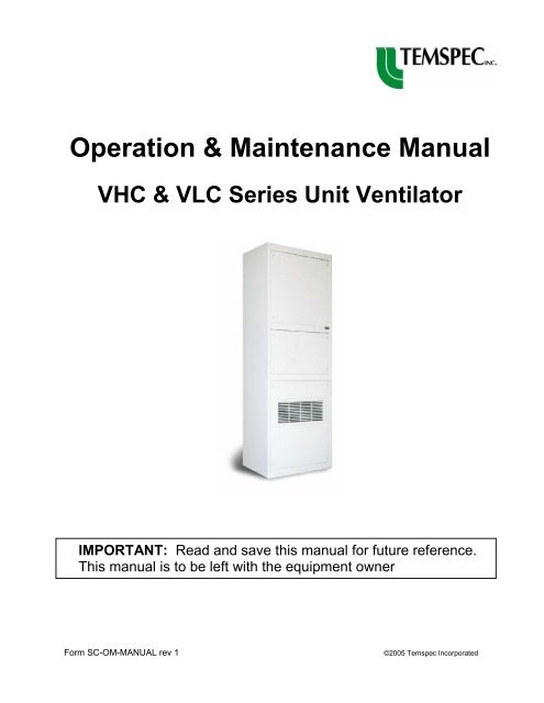
<strong>Operation</strong> & <strong>Maintenance</strong> <strong>Manual</strong><br />
VHC & VLC Series Unit Ventilator<br />
IMPORTANT: Read and save this manual for future reference.<br />
This manual is to be left with the equipment owner<br />
Form SC-OM-MANUAL rev 1 ©2005 Temspec Incorporated
INTRODUCTION<br />
Table Of Contents<br />
About the Unit Ventilator ….……………………………………………………………………1<br />
Nomenclature for Unit Ventilators with Self-Contained Cooling ….……………………1<br />
TYPICAL UNIT LAYOUT<br />
Model VLC 24, VLC 30, VLC 36 .………………………………………………………………2<br />
Model VLC 48, VLC 60 - (ducted) ….……………………………………………………………3<br />
Model VLC 48, VLC 60 - (freeblow) .………………………………………………………4<br />
Model VHC 30, VHC 36, VHC 48, VHC 60 .………………………………………………5<br />
OPERATION<br />
Sequence of <strong>Operation</strong> ..………………………………………………………………………6<br />
Hot Water Circuit .……………………………………………………………………………….7<br />
Refrigeration Circuit ………....……………………………………………………………………..8<br />
Electrical Circuit ……….….……………………………………………………………………9<br />
Dampers ……….………….……………………………………………………………………9<br />
Optional Powered Exhaust ….………….…………………………………………………………9<br />
Filtration ……….………….………………………………………………………………..…..9<br />
MAINTENANCE<br />
Servicing the Unit ………….………….………………………………………………………..10<br />
<strong>Maintenance</strong> Schedule ….………….……………………………………………………..…10<br />
Changing the Filters ………….………….……………………………………………………..…11<br />
Cleaning the Condenser Coil …….………………………………………………….…..…11<br />
Cleaning the Evaporator Coil …….………………………………………………………...12<br />
Motors ………………………….…………………………………………………………...12<br />
TROUBLESHOOTING<br />
Basic Troubleshooting Guidelines …..…………………………………………………………..13<br />
REPLACEMENT PARTS<br />
Limited Warranty ..……………………...………………………………………………………14<br />
Part Sales …………..………………………..…….…………………………………………....14
ABOUT THE UNIT VENTILATOR<br />
INTRODUCTION<br />
The Temspec unit ventilator was designed as a means for providing heating, cooling and<br />
ventilation to the classroom. Our goal is to help create an enhanced learning environment<br />
by focusing on the following points when designing our equipment:<br />
• TEMPERATURE & HUMIDITY CONTROL<br />
• AIR DISTRIBUTION<br />
• SOUND ATTENUATION<br />
By introducing the vertical unit ventilator into the classroom, superior control can be<br />
obtained for each room. Because of the unit’s ducting capabilities, an even distribution of<br />
air can be achieved throughout the room. The unit ventilator is constructed with heavy<br />
guage metal and sound absorbing insulation for optimal sound attenuation.<br />
By applying sound engineering principles and through continuous testing, the highest<br />
quality of performance is obtained in the unit ventilators.<br />
NOMENCLATURE FOR UNIT VENTILATORS WITH SELF-CONTAINED COOLING<br />
V LC<br />
36<br />
LC = Low Condensing Section<br />
HC = High Condensing Section<br />
Vertical Unit<br />
24 = 2.0 tons of Cooling<br />
30 = 2.5 tons of Cooling<br />
36 = 3.0 tons of Cooling<br />
48 = 4.0 tons of Cooling<br />
60 = 5.0 tons of cooling<br />
-1-
Models VLC 24, VLC 30, VLC36<br />
1<br />
2<br />
3<br />
4<br />
5<br />
E.A.<br />
O.A.<br />
C.A.<br />
C.E.<br />
E.A.<br />
S.A. Supply Air<br />
R.A. Return Air<br />
TYPICAL LAYOUT<br />
23"<br />
SIDE SECTION<br />
S.A.<br />
S.A.<br />
R.A.<br />
O.A. Outdoor Air<br />
C.A. Condenser Air<br />
1. Barometric relief damper assembly (optional).<br />
2. Hot water coil. Optional electric or steam<br />
coil available.<br />
3. Dual supply air fans.<br />
4. Outdoor air damper.<br />
5. Condenser coil.<br />
6. DX cooling coil.<br />
7. Drain pan.<br />
8. Electrical box / controls enclosure.<br />
9. Mixed air damper actuator.<br />
10. Filter.<br />
6<br />
7<br />
8<br />
9<br />
10<br />
11<br />
12<br />
13<br />
Duct By<br />
Others<br />
14<br />
15<br />
16<br />
17<br />
18<br />
19<br />
S.A.<br />
33"<br />
FRONT ELEVATION<br />
S.A.<br />
C.E. Condenser Exhaust Air<br />
E.A. Room Exhaust Air<br />
93"<br />
11. Return air damper.<br />
12. Single condenser fan.<br />
13. Compressor.<br />
14. Ceiling tile.<br />
15. Top extension /duct shroud to suit<br />
ceiling height (optional).<br />
16. Coil access panel (removable) with optional<br />
double deflection discharge grille.<br />
17. Filter access panel, hinged.<br />
18. Removable access panel.<br />
19. Heavy duty return air grille.<br />
NOTE: The component arrangement shown above may vary slightly from that in the unit ventilator supplied.<br />
-2-<br />
H
TYPICAL LAYOUT<br />
Models VLC 48, VLC 60 (ducted configuration)<br />
1<br />
2<br />
3<br />
4<br />
5<br />
6<br />
O.A.<br />
E.A.<br />
C.A.<br />
C.E.<br />
E.A.<br />
30"<br />
SIDE SECTION<br />
S.A. Supply Air<br />
R.A. Return Air<br />
S.A.<br />
R.A.<br />
Duct By<br />
Others<br />
O.A. Outdoor Air<br />
C.A. Condenser Air<br />
1. Barometric relief damper assembly (optional).<br />
2. DX cooling coil.<br />
3. Drain pan.<br />
4. Spring return mixed air damper actuator.<br />
5. Outdoor air damper.<br />
6. Condenser coil.<br />
7. Dual supply air fans.<br />
8. Hot water coil. Optional electric or steam<br />
coil available.<br />
9. Electrical box / controls enclosure.<br />
10. Filters.<br />
7<br />
8<br />
9<br />
10<br />
11<br />
12<br />
13<br />
14<br />
15<br />
16<br />
17<br />
18<br />
19<br />
44"<br />
FRONT ELEVATION<br />
C.E. Condenser Exhaust Air<br />
E.A. Room Exhaust Air<br />
11. Return air damper.<br />
12. Dual condenser fans.<br />
13. Compressor.<br />
14. Ceiling tile.<br />
15. Top extension / duct shroud to suit<br />
ceiling height (optional).<br />
16. Coil access panel, removable.<br />
17. Filter access panel, hinged.<br />
18. Removable access panel.<br />
19. Heavy duty return air grille.<br />
NOTE: The component arrangement shown above may vary slightly from that in the unit ventilator supplied.<br />
-3-<br />
H<br />
93"
TYPICAL LAYOUT<br />
Models VLC 48, VLC 60 (freeblow configuration)<br />
1<br />
2<br />
3<br />
4<br />
5<br />
6<br />
O.A.<br />
C.A.<br />
C.E.<br />
30"<br />
SIDE SECTION<br />
S.A. Supply Air<br />
R.A. Return Air<br />
R.A.<br />
O.A. Outdoor Air<br />
C.A. Condenser Air<br />
1. Hot water coil. Optional electric or steam<br />
coil available.<br />
2. DX cooling coil.<br />
3. Drain pan.<br />
4. Dual supply air fans.<br />
5. Outdoor air damper.<br />
6. Condenser coil.<br />
7. Supply air grilles (double deflection).<br />
8. Electrical box / controls enclosure.<br />
9. Mixed air damper actuator.<br />
10. Filters.<br />
7<br />
8<br />
10<br />
11<br />
12<br />
13<br />
14<br />
15<br />
S.A. S.A. S.A.<br />
9<br />
16<br />
17<br />
18<br />
19<br />
44"<br />
FRONT ELEVATION<br />
93"<br />
C.E. Condenser Exhaust Air<br />
11. Return air damper.<br />
12. Compressor.<br />
13. Dual condenser fans.<br />
14. Ceiling tile.<br />
15. Top extension to suit ceiling height<br />
(optional).<br />
16. Coil access panel (removable) with front<br />
double deflection grille.<br />
17. Filter access panel, hinged.<br />
18. Removable access panel.<br />
19. Heavy duty return air grille.<br />
NOTE: The component arrangement shown above may vary slightly from that in the unit ventilator supplied.<br />
-4-<br />
H
TYPICAL LAYOUT<br />
Models VHC 30, VHC 36, VHC 48, VHC 60 (ducted configuration)<br />
1<br />
2<br />
3<br />
4<br />
5<br />
6<br />
2<br />
O.A.<br />
C.A.<br />
C.E. / E.A.<br />
30"<br />
SIDE SECTION<br />
S.A. Supply Air<br />
R.A. Return Air<br />
S.A.<br />
E.A.<br />
R.A. / E.A.<br />
O.A. Outdoor Air<br />
C.A. Condenser Air<br />
1. DX cooling coil.<br />
2. Drain pan.<br />
3. Outdoor air damper.<br />
4. Mixed air damper actuator.<br />
5. Dual condenser exhaust / powered exhaust<br />
fans.<br />
6. Condenser coil.<br />
7. Supply air fan(s).<br />
8. Hot Water Coil. Optional electric or steam<br />
coil available.<br />
9. Electrical box / controls enclosure.<br />
7<br />
8<br />
9<br />
10<br />
11<br />
12<br />
13<br />
14<br />
15<br />
16<br />
17<br />
18<br />
S.A.<br />
44"<br />
FRONT ELEVATION<br />
C.E. Condenser Exhaust Air<br />
E.A. Room Exhaust Air<br />
10. Filters.<br />
11. Return air damper.<br />
12. Modulating powered exhaust damper<br />
and actuator module (optional).<br />
13. Compressor.<br />
14. Ceiling tile.<br />
15. Top extension / duct shroud to suit<br />
ceiling height (optional).<br />
16. Filter/coil hinged access panel.<br />
17. Removable access panel.<br />
18. Heavy duty return air grille.<br />
NOTE: The component arrangement shown above may vary slightly from that in the unit ventilator supplied.<br />
-5-<br />
H<br />
93"
Typical Modes Of <strong>Operation</strong><br />
OPERATION<br />
The following are typical modes of operation for a classroom unit ventilator. Please refer to the manual<br />
provided by the controls contractor for a more specific controls sequence.<br />
1. Unoccupied Mode<br />
During the “unoccupied heat” mode (night set-back) space temperature is maintained by a signal from the<br />
thermostat/controller to either the modulating control valve or electric coil. The powered exhaust damper<br />
(if applicable) and the outdoor air damper are fully closed and the return air damper is fully open. The<br />
supply air fan operates on call for heating or cooling from the thermostat/controller.<br />
2. Occupied Mode<br />
The unit ventilator is switched to “occupied mode” by the thermostat/controller. In this mode a signal is<br />
sent from the thermostat/controller to either the modulating control valve or electric coil to maintain room<br />
temperature at set point. The outdoor air damper is held at a minimum position in the heating and<br />
mechanical cooling modes. The supply air fan runs continuously.<br />
3. Economizer (up to 100% outdoor air)<br />
The first stage of cooling is the economizer mode during which all stages of heating are off. The outdoor<br />
air and the return air dampers modulate to maintain the room temperature at the economizer set point. If<br />
the mixed air falls to a programmed temperature (usually 52°F) the outdoor air damper will modulate<br />
towards closed until the mixed air temperature rises again (typically to 55°F). In this free cooling mode<br />
the ability of the unit ventilator to provide sufficient cooling is limited only by the outdoor air temperature<br />
and the total C.F.M. rating of the unit.<br />
4. Mechanical Cooling<br />
The unit ventilator utilizes the self-contained refrigeration section incorporated within the unit (DX coil,<br />
condenser coil, compressor and refrigerant expansion device). The system maintains the cooling set<br />
point by cycling on call from the thermostat/controller. In this mode the outdoor air damper will return to<br />
minimum position.<br />
5. Freeze Protection<br />
For units with a steam or hot water coil, freeze protection is usually incorporated. This can be by either a<br />
low limit temperature control (autoreset or manual reset) or by using a supply air sensor and programming<br />
from the controller. When a mixed air temperature is determined to be too low, then the outdoor air<br />
damper will close and the control valve will fully open. The fan can also be shut down until the<br />
temperature returns to normal levels. The low limit temperature control (freezestat) should be located at<br />
the leaving air side of the heating coil.<br />
6. Humidistat & Hot Gas Reheat (Optional for VHC series units only)<br />
A room humidistat sensor is included in the return air stream. The humidistat has a set point of 55% R.H.<br />
(adjustable). When the room temperature falls to the cooling set point and the humidistat set point has<br />
not been satisfied, the hot gas reheat coil provides reheat to maintain the cooling set point in the room (to<br />
avoid over cooling in the space). The compressor operates under this condition. When the humidity set<br />
point is satisfied, the reheat coil is de-energized.<br />
-6-
Hot Water Circuit<br />
The following are typical hot water piping schematics for a unit ventilator. Please refer to the unit<br />
ventilator shop drawings for a more specific layout.<br />
2-way Control Valve<br />
<strong>Manual</strong> Air Vent<br />
MIXED<br />
AIR HOT<br />
WATER<br />
COIL<br />
3-way Control Valve<br />
<strong>Manual</strong> Air Vent<br />
MIXED<br />
AIR<br />
Hot Water With 2-way Control Valve<br />
Strainer<br />
MV<br />
Balancing Valve<br />
Isolation Valve<br />
HWR<br />
HWS<br />
Isolation Valve<br />
Hot Water With 3-way Control Valve<br />
HOT<br />
WATER<br />
COIL<br />
MV<br />
Strainer<br />
NO<br />
NC<br />
C<br />
-7-<br />
Balancing Valve<br />
Isolation Valve<br />
HWR<br />
HWS<br />
Isolation Valve
Refrigeration Circuit<br />
The following is a typical self-contained refrigeration circuit.<br />
MIXED<br />
AIR<br />
OUTDOOR<br />
AIR<br />
EVAPORATOR<br />
COIL<br />
CONDENSER<br />
COIL<br />
Anti-Ice Control<br />
Distributor<br />
Metering Device<br />
Sight Glass, Moisture Indicator<br />
-8-<br />
Pressure Test Port<br />
Filter Dryer<br />
High Limit Pressure<br />
Cut-Out<br />
Low Limit Pressure<br />
Cut-Out<br />
Compressor<br />
Crankcase Heater
Electrical Circuit<br />
The electrical circuit in the unit ventilator is dependent on the controller and sequence that<br />
is being utilized. The unit can be supplied with a 208V, 277V or 460V power supply. The<br />
unit is equipped with an unfused service disconnect. A copy of the electrical schematic can<br />
be found folded in a pouch inside of each unit ventilator, located on the electrical enclosure<br />
or supply air fan housing.<br />
Dampers<br />
The outdoor air dampers and return air dampers are mechanically linked. As the outdoor<br />
air damper opens, the return air damper closes. A spring return damper actuator is<br />
connected to a linkage set that extends to both sets of dampers. The damper actuator<br />
manufacturer can vary. Please refer to the wiring schematic for the damper actuator model<br />
type.<br />
Powered Exhaust (optional)<br />
Internal powered exhaust is an optional feature that is provided with the VHC series. This<br />
feature comes with a spring return damper actuator that is separate from the one used to<br />
control the outside air and return air dampers. However, the powered exhaust damper<br />
actuator is electrically linked to the outside air damper. As the outside air damper opens,<br />
so does the powered exhaust damper.<br />
Filtration<br />
Typically 1” disposable filters are provided in the unit. Please refer to the “shop drawings”<br />
for specific details on filter construction and thickness. Below are sizes and quantity per<br />
unit for the different model types.<br />
Model Number Filter Size Quantity Per Unit<br />
VLC 24, VLC 30, VLC 36 20” x 24” nominal 1<br />
VLC 48, VLC 60 16” x 24” nominal 2<br />
VHC 36, VHC 48, VHC 60 20” x 25” nominal 2<br />
-9-
Servicing The Unit<br />
MAINTENANCE<br />
<strong>Maintenance</strong> to the unit is accomplished by removing the front access panels. Typically the<br />
panels are secured by heavy duty phillips (star or cross shape) head screws. When<br />
removing the access panel, loosen but do not remove the screws. Carefully store the panel<br />
in a place where it will not get damaged. Use caution as some access panels are heavy.<br />
CAUTION: Disconnect power at the remote circuit breaker before servicing the<br />
unit.<br />
The unit comes fitted with a “fan kill switch” that de-energizes the supply air fan(s) when the<br />
filter access panel is removed / opened. This will only disconnect the power to the supply<br />
air fans. Be sure to disconnect ALL power by turning the remote circuit breaker to the off<br />
position.<br />
To access the condenser section, you must remove a secondary panel located directly<br />
behind the return air access panel.<br />
<strong>Maintenance</strong> Schedule<br />
Interior and exterior environmental conditions will influence the required frequency of coil<br />
cleaning and filter change operations . The following is a typical maintenance schedule for<br />
a classroom unit ventilator.<br />
Initial Start-Up – Change out construction filters.<br />
– Verify that air paths are free of construction debris and that fans turn<br />
freely<br />
– Verify compressor rotation<br />
– Verify outdoor air minimum position<br />
Every 3 months – Change filters<br />
Every 12 months – Clean condenser coil (at the beginning of the cooling season)<br />
– Vacuum out evaporator drain pan<br />
– Vacuum any loose debris from unit’s interior condenser section<br />
– Clean strainer in the hydronic circuit (if applicable)<br />
Every 24 months – Clean evaporator coil<br />
– Vacuum any loose debris from unit’s interior return air section<br />
– Inspect dampers to ensure that there is a proper seal when closed<br />
-10-
Changing the Filters<br />
The outdoor and indoor conditions of your area will determine the frequency of filter<br />
changes. Temspec recommends that the filters be changed every 3 months as a rule-ofthumb.<br />
Note that dirty filters adversely affect the overall performance of the unit.<br />
To change the filters, open / remove the filter access panel by loosening the phillips head<br />
screws. On the VLC series units, simply slide out the old filters and replace them with the<br />
new ones. On the VHC series units, unclip the filters. Be sure to note the airflow direction<br />
that is marked on the filter(s).<br />
Cleaning the Condenser Coil<br />
The following are the recommended steps to cleaning the condenser coil.<br />
CAUTION: Disconnect power at the remote circuit breaker before servicing the<br />
unit.<br />
1. Clean debris and leaves from between the blades of the exterior louver.<br />
2. VLC series: Unfasten the removable section of the louver from the exterior side<br />
of the building.<br />
VHC series: Remove the unit ventilator return air access panel and condenser<br />
access panel from inside the room.<br />
3. Vacuum the entering air face of the condenser coil using a soft bristle<br />
attachment. Be careful not to bend any of the aluminum fins on the coil.<br />
4. Use a foaming coil cleaning chemical (such as “Foam-Brite” from NU-CALGON,<br />
product# 4178-08, www.nucalgon.com). Follow the manufacturers instructions<br />
for safe handling and personal protective equipment.<br />
WARNING: Do NOT use condenser coil cleaning compounds on the evaporator or<br />
hot water coils.<br />
WARNING: Do NOT use chlorine based cleaners or anti-fungal treatments on the<br />
aluminum fins of any coil.<br />
Depending on the wind conditions and building pressurization, a portable fan<br />
may be required in the room to ensure that the fumes are properly exhausted out<br />
of the building (VHC series only).<br />
-11-
CONTINUED<br />
5. Using a wet / dry shop vac, remove any rinse water from the condenser coil drain<br />
pan.<br />
6. Replace access panels and return to normal operation.<br />
Cleaning the Evaporator and Hot Water Coils<br />
CAUTION: Disconnect power before servicing the unit.<br />
WARNING: Do NOT use condenser coil cleaning compounds on the evaporator or<br />
hot water coils.<br />
To clean the evaporator coil, purchase a suitable evaporator coil cleaning solution such as<br />
those offered by NU-CALGON. Follow the manufacturer’s instructions for use.<br />
Note: Chlorine based or anti-fungal “pucks” or “socks” are acceptable when placed in the<br />
evaporator drain pan. Be sure to vacuum the drain pan after the cleaning process<br />
is complete and prior to adding the anti-fungal component.<br />
WARNING: Do NOT use chlorine based cleaners or anti-fungal treatments on the<br />
aluminum fins of any coil.<br />
Motors<br />
Temspec provides motors that are permanently lubricated. No maintenance is required.<br />
-12-
TROUBLESHOOTING<br />
Basic Trouble Shooting Guidelines<br />
Problem Action Required<br />
●Supply fan not running ●Verify that the disconnect is in the “on” position<br />
●Verify that door micro-switch “kill switch” is<br />
completely depressed and operating correctly<br />
●Verify that thermostat / controller is not in<br />
unoccupied mode (night set-back)<br />
●Check manual reset controls (electric heat, high<br />
refrigerant pressure controls and low limit<br />
temperature control) and ensure that they have<br />
not been tripped.<br />
●Check the fan relay to observe if it is energizing<br />
and de-energizing properly<br />
●Check that the 24V transformer is working<br />
properly<br />
●Ensure that the wire connections are secured<br />
properly<br />
●Compressor and condensing ●Ensure that there are no obstructions<br />
fans cycle on and off to the condenser air path. Obstructions will cause<br />
the unit to cut-out on high head pressure.<br />
●Check refrigerant charge. If the charge is to low,<br />
the unit will cut-out on low pressure. The<br />
Refrigerant type and amount is posted on the<br />
silver CSA label located on the electrical enclosure<br />
or fan housing.<br />
-13-
Limited Warranty<br />
REPLACEMENT PARTS<br />
TEMSPEC INCORPORATED warrants the equipment for a period of one year.<br />
This warranty covers the provision of labor to replace defective parts; defective parts to be<br />
supplied at no charge. The work is to be performed only by Temspec Inc, or it’s assigned<br />
agents.<br />
For this warranty to remain valid, the unit(s) must be maintained in accordance to the<br />
manufacturer’s recommendations. It does not cover parts damaged by vandalism,<br />
improper installation or abuse.<br />
The warranty period commences on the day that the unit is commissioned by the<br />
mechanical contractor for operation.<br />
Part Sales<br />
Contact the factory at: 1-888-TEMSPEC or (905) 670-3595<br />
hvac@temspec.com<br />
Ask for “PART SALES”.<br />
Be sure to have the unit serial number available. It is located on the silver CSA label, on<br />
the electrical enclosure or fan housing, inside of the unit.<br />
-14-