SUPERCLAUS ®/ DynaWave ® process
SUPERCLAUS ®/ DynaWave ® process
SUPERCLAUS ®/ DynaWave ® process

Create successful ePaper yourself
Turn your PDF publications into a flip-book with our unique Google optimized e-Paper software.
CLAUS TAIL GAS TREATING<br />
required quantity of combustion air is calculated<br />
by measuring the amine acid gas<br />
and the sour water acid gas (SWS) flows.<br />
The total air demand is then compared with<br />
the feedback signal from the air demand<br />
analyser (located upstream of the SUPER-<br />
CLAUS <strong>®</strong> reactor) to adjust air supply to the<br />
thermal stage. The ABC system ensures<br />
that the required H 2 S content is achieved at<br />
the inlet of the <strong>SUPERCLAUS</strong> <strong>®</strong> stage for optimum<br />
sulphur recovery efficiency of the unit.<br />
<strong>SUPERCLAUS</strong> <strong>®</strong> catalyst is not sensitive<br />
to excess O 2 , nor the presence of SO 2 or<br />
H 2 O because the selective oxidation reaction<br />
is not equilibrium based like the Claus<br />
reaction:<br />
Claus reaction<br />
2H 2S + SO 2 ↔ 3S + 2H 2O<br />
<strong>SUPERCLAUS</strong> <strong>®</strong> reaction<br />
H 2S + 1 / 2 O 2 → S + H 2O<br />
<strong>SUPERCLAUS</strong> <strong>®</strong> is compatible with conventional<br />
SRU designs that properly destroy<br />
ammonia present in the SWS feed gases<br />
with no added risk to ammonia salt deposition.<br />
Close to 50% of the <strong>SUPERCLAUS</strong> <strong>®</strong><br />
installations in the world are effectively operating<br />
in ammonia <strong>process</strong>ing Claus units.<br />
<strong>SUPERCLAUS</strong> <strong>®</strong> is a non-cyclic <strong>process</strong><br />
that has repeatedly shown simplicity of<br />
operation, high online reliability, and sulphur<br />
recovery guarantees up to 99.3%.<br />
<strong>DynaWave</strong><strong>®</strong> reverse jet scrubber<br />
<strong>DynaWave</strong> <strong>®</strong> is a unique wet gas scrubber<br />
technology which offers a number of advantages<br />
in the SRU application. The most<br />
important challenges in the SRU scrubber<br />
application are turndown, the need for a high<br />
liquid to gas (L/G) ratio, and the requirement<br />
for oxidation. An SRU tail gas scrubber must<br />
be able to handle a varying range of inlet<br />
flow conditions and inlet SO 2 concentrations<br />
which occur during the critical stages of<br />
startup, shutdown and malfunction (SSM).<br />
Oxidation of the liquid effluent may be<br />
required in order to reduce chemical oxygen<br />
demand (COD) to levels acceptable to wastewater<br />
treatment facilities.<br />
Wet gas scrubbers circulate a liquid<br />
reagent which absorbs SO 2. The liquid-togas<br />
(L/G) ratio is a key <strong>process</strong> parameter<br />
for a scrubber, and must be high enough in<br />
the SRU application to fully quench the hot<br />
<strong>process</strong> gas and absorb the SO 2 without<br />
suppressing the pH in the absorber reaction/contact<br />
zone. Momentary pH depression<br />
in the contact zone can be avoided<br />
with high L/G ratios. In general, higher liquid-to-gas<br />
ratios will result in higher SO 2<br />
removal efficiencies.<br />
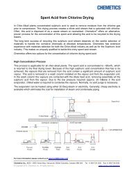
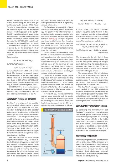
The <strong>DynaWave</strong> <strong>®</strong> achieves high L/G and<br />
infinite turndown using reverse jet technology.<br />
Tail gas from the SRU incinerator, or<br />
waste heat boiler, enters the scrubber inlet<br />
duct and collides with the circulating scrubber<br />
liquor (see Fig. 2). The liquor is injected<br />
countercurrent to the gas flow through a<br />
large bore, open throat nozzle known as<br />
the reverse jet nozzle. The contact zone<br />
where the gas and liquor collide is referred<br />
to as the froth zone.<br />
The froth zone is an area of high mass<br />
transfer and turbulence where quench and<br />
acid gas absorption take place simultaneously.<br />
The amount of recirculation liquid<br />
required to develop the froth zone is calculated<br />
based on the maximum <strong>process</strong><br />
conditions. The liquid flow is constant,<br />
which means that when the inlet gas flow<br />
decreases, the L/G increases and acid gas<br />
removal efficiency increases.<br />
Compared to packed towers, where<br />
high liquid flow rates can cause flooding,<br />
the <strong>DynaWave</strong> <strong>®</strong> can operate at liquid circulation<br />
rates which are 5 to 7 times normal<br />
packed tower flow rates. This allows the<br />
<strong>DynaWave</strong> <strong>®</strong> to handle extremely high levels<br />
of SO 2 , present at SSM when a portion of<br />
the SRU must be bypassed.<br />
To react with SO 2 , owners prefer to use<br />
sodium based reagents such as caustic<br />
(NaOH). The reaction between SO 2 and caustic<br />
is a strong acid-base reaction and is practically<br />
instantaneous. Once the SO 2 is in<br />
solution, the reaction proceeds as follows:<br />
Fig 2: <strong>DynaWave</strong> <strong>®</strong> reverse jet scrubber<br />
effluent<br />
dirty gas in<br />
pump<br />
clean gas out<br />
make-up<br />
SO 2 (v) + NaOH (l) → NaHSO 3<br />
SO 2 (v) + 2NaOH (l) → Na 2 SO 3 + H 2 O<br />
In most cases, the sodium sulphite/<br />
sodium bisulphite salts formed in the<br />
above reactions must be further oxidised<br />
to sodium sulphate in order to reduce the<br />
COD of the scrubber effluent to acceptable<br />
levels. The reactions are as follows:<br />
NaHSO 3(soluble salt) + 0.5O 2 + NaOH →<br />
Na 2SO 4 (soluble salt) + H 2O<br />
Na 2 SO 3 (soluble salt) + 0.5O 2 → Na 2 SO 4<br />
(soluble salt)<br />
After the gas exits the inlet duct, it flows<br />
through the top portion of the vessel and<br />
exits to atmosphere through an integral<br />
stack. Before exiting the vessel, the clean,<br />
saturated gas flows through a set of<br />
chevrons which maximise liquid droplet<br />
removal from the gas stream.<br />
The scrubbing liquor falls to the bottom<br />
of the scrubber vessel which is used as a<br />
reservoir for continuous feed to the recirculation<br />
pumps. The vessel also provides<br />
the oxidation zone for in-situ oxidation of<br />
sulphite salts to sulphate salts.<br />
The <strong>DynaWave</strong> <strong>®</strong> wet gas scrubber has<br />
been installed in over 300 applications<br />
worldwide. The <strong>DynaWave</strong> <strong>®</strong> has been designed<br />
for 11 SRU tail gas treatment projects in the<br />
United States, and installed in seven. The<br />
<strong>DynaWave</strong> <strong>®</strong> is leading all other SO 2 absorption<br />
technologies in total SRU installations.<br />
<strong>SUPERCLAUS</strong><strong>®</strong>/<strong>DynaWave</strong><strong>®</strong> <strong>process</strong><br />
By combining the <strong>SUPERCLAUS</strong> <strong>®</strong> and<br />
<strong>DynaWave</strong> <strong>®</strong> technologies, the overall system<br />
can achieve greater than 99.9% sulphur<br />
removal at compelling capital and operating<br />
costs. Approximately 99.0% of the H 2 S is<br />
captured and recovered as elemental sulphur<br />
by the <strong>SUPERCLAUS</strong> <strong>®</strong> and the remaining<br />
sulphur is scrubbed and converted to<br />
Na 2 SO 4 by the <strong>DynaWave</strong> <strong>®</strong> . Figure 3 is a<br />
schematic of the combined technologies:<br />
Technology comparison<br />
When comparing <strong>SUPERCLAUS</strong> <strong>®</strong> /<strong>DynaWave</strong> <strong>®</strong><br />
with an amine-based TGTU, one must fully<br />
assess the advantages or disadvantages<br />
of each factor, e.g. capital costs, operating<br />
costs, number of equipment items, plot<br />
foot-print, liquid discharges, chemical<br />
requirements, achievable sulphur recovery<br />
rate and operability/reliability.<br />
2 Sulphur 326 | January-February 2010