SUPERCLAUS ®/ DynaWave ® process
SUPERCLAUS ®/ DynaWave ® process
SUPERCLAUS ®/ DynaWave ® process

You also want an ePaper? Increase the reach of your titles
YUMPU automatically turns print PDFs into web optimized ePapers that Google loves.
Selection of an appropriate and cost<br />
effective tail gas treatment <strong>process</strong><br />
to follow existing Claus plants is a<br />
challenge facing refiners and natural gas<br />
plant owners around the world. New emission<br />
regulations, interest in increasing sulphur<br />
recovery and <strong>process</strong>ing of higher<br />
sulphur crudes are the main drivers.<br />
The most common approach is to<br />
install an amine-based Tail Gas Treatment<br />
Unit (TGTU) however lower installed cost<br />
and higher reliability can be achieved by<br />
combining two well established <strong>process</strong>es,<br />
Jacobs <strong>SUPERCLAUS</strong> <strong>®</strong> selective oxidation<br />
<strong>process</strong> and MECS’ <strong>DynaWave</strong> <strong>®</strong> wet gas<br />
scrubber technology. Owners can lower<br />
capital and operating costs significantly<br />
with this solution.<br />
<strong>SUPERCLAUS</strong><strong>®</strong><br />
The <strong>SUPERCLAUS</strong> <strong>®</strong> <strong>process</strong> was developed<br />
to catalytically recover elemental sulphur<br />
from H 2 S containing Claus tail gases to<br />
improve the overall sulphur recovery level<br />
of the sulphur recovery facility. The <strong>process</strong><br />
was commercially demonstrated in 1988,<br />
and today more than 160 units are under<br />
license and over 140 are in operation.<br />
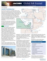
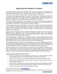
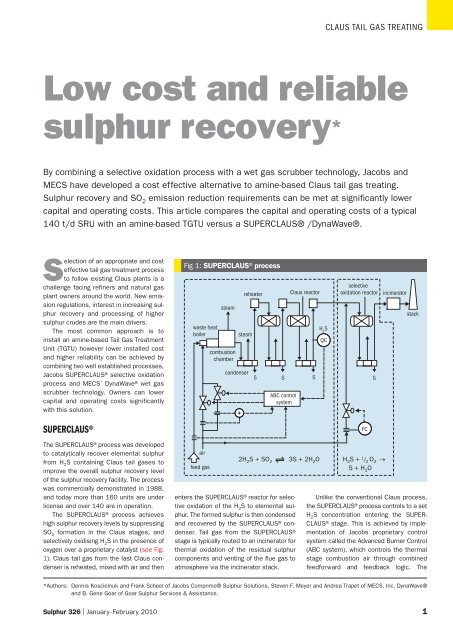
The <strong>SUPERCLAUS</strong> <strong>®</strong> <strong>process</strong> achieves<br />
high sulphur recovery levels by suppressing<br />
SO 2 formation in the Claus stages, and<br />
selectively oxidising H 2S in the presence of<br />
oxygen over a proprietary catalyst (see Fig.<br />
1). Claus tail gas from the last Claus condenser<br />
is reheated, mixed with air and then<br />
enters the <strong>SUPERCLAUS</strong> <strong>®</strong> reactor for selective<br />
oxidation of the H 2 S to elemental sulphur.<br />
The formed sulphur is then condensed<br />
and recovered by the <strong>SUPERCLAUS</strong> <strong>®</strong> condenser.<br />
Tail gas from the <strong>SUPERCLAUS</strong> <strong>®</strong><br />
stage is typically routed to an incinerator for<br />
thermal oxidation of the residual sulphur<br />
components and venting of the flue gas to<br />
atmosphere via the incinerator stack.<br />
CLAUS TAIL GAS TREATING<br />
Low cost and reliable<br />
sulphur recovery *<br />
By combining a selective oxidation <strong>process</strong> with a wet gas scrubber technology, Jacobs and<br />
MECS have developed a cost effective alternative to amine-based Claus tail gas treating.<br />
Sulphur recovery and SO 2 emission reduction requirements can be met at significantly lower<br />
capital and operating costs. This article compares the capital and operating costs of a typical<br />
140 t/d SRU with an amine-based TGTU versus a <strong>SUPERCLAUS</strong><strong>®</strong> /<strong>DynaWave</strong><strong>®</strong>.<br />
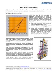
Fig 1: <strong>SUPERCLAUS</strong> <strong>®</strong> <strong>process</strong><br />
waste heat<br />
boiler<br />
air<br />
feed gas<br />
steam<br />
combustion<br />
chamber<br />
condenser<br />
Unlike the conventional Claus <strong>process</strong>,<br />
the <strong>SUPERCLAUS</strong> <strong>®</strong> <strong>process</strong> controls to a set<br />
H 2 S concentration entering the SUPER-<br />
CLAUS <strong>®</strong> stage. This is achieved by implementation<br />
of Jacobs proprietary control<br />
system called the Advanced Burner Control<br />
(ABC system), which controls the thermal<br />
stage combustion air through combined<br />
feedforward and feedback logic. The<br />
*Authors: Dennis Koscielnuk and Frank Scheel of Jacobs Comprimo<strong>®</strong> Sulphur Solutions, Steven F. Meyer and Andrea Trapet of MECS, Inc. <strong>DynaWave</strong><strong>®</strong><br />
and B. Gene Goar of Goar Sulphur Services & Assistance.<br />
Sulphur 326 | January-February 2010 1<br />
steam<br />
+<br />
reheater<br />
S<br />
S<br />
ABC control<br />
system<br />
Claus reactor<br />
S<br />
H 2 S<br />
selective<br />
oxidation reactor incinerator<br />
2H 2S + SO 2 3S + 2H 2O H 2S + 1 / 2 O 2 →<br />
S + H 2O<br />
QC<br />
FC<br />
S<br />
stack
CLAUS TAIL GAS TREATING<br />
required quantity of combustion air is calculated<br />
by measuring the amine acid gas<br />
and the sour water acid gas (SWS) flows.<br />
The total air demand is then compared with<br />
the feedback signal from the air demand<br />
analyser (located upstream of the SUPER-<br />
CLAUS <strong>®</strong> reactor) to adjust air supply to the<br />
thermal stage. The ABC system ensures<br />
that the required H 2 S content is achieved at<br />
the inlet of the <strong>SUPERCLAUS</strong> <strong>®</strong> stage for optimum<br />
sulphur recovery efficiency of the unit.<br />
<strong>SUPERCLAUS</strong> <strong>®</strong> catalyst is not sensitive<br />
to excess O 2 , nor the presence of SO 2 or<br />
H 2 O because the selective oxidation reaction<br />
is not equilibrium based like the Claus<br />
reaction:<br />
Claus reaction<br />
2H 2S + SO 2 ↔ 3S + 2H 2O<br />
<strong>SUPERCLAUS</strong> <strong>®</strong> reaction<br />
H 2S + 1 / 2 O 2 → S + H 2O<br />
<strong>SUPERCLAUS</strong> <strong>®</strong> is compatible with conventional<br />
SRU designs that properly destroy<br />
ammonia present in the SWS feed gases<br />
with no added risk to ammonia salt deposition.<br />
Close to 50% of the <strong>SUPERCLAUS</strong> <strong>®</strong><br />
installations in the world are effectively operating<br />
in ammonia <strong>process</strong>ing Claus units.<br />
<strong>SUPERCLAUS</strong> <strong>®</strong> is a non-cyclic <strong>process</strong><br />
that has repeatedly shown simplicity of<br />
operation, high online reliability, and sulphur<br />
recovery guarantees up to 99.3%.<br />
<strong>DynaWave</strong><strong>®</strong> reverse jet scrubber<br />
<strong>DynaWave</strong> <strong>®</strong> is a unique wet gas scrubber<br />
technology which offers a number of advantages<br />
in the SRU application. The most<br />
important challenges in the SRU scrubber<br />
application are turndown, the need for a high<br />
liquid to gas (L/G) ratio, and the requirement<br />
for oxidation. An SRU tail gas scrubber must<br />
be able to handle a varying range of inlet<br />
flow conditions and inlet SO 2 concentrations<br />
which occur during the critical stages of<br />
startup, shutdown and malfunction (SSM).<br />
Oxidation of the liquid effluent may be<br />
required in order to reduce chemical oxygen<br />
demand (COD) to levels acceptable to wastewater<br />
treatment facilities.<br />
Wet gas scrubbers circulate a liquid<br />
reagent which absorbs SO 2. The liquid-togas<br />
(L/G) ratio is a key <strong>process</strong> parameter<br />
for a scrubber, and must be high enough in<br />
the SRU application to fully quench the hot<br />
<strong>process</strong> gas and absorb the SO 2 without<br />
suppressing the pH in the absorber reaction/contact<br />
zone. Momentary pH depression<br />
in the contact zone can be avoided<br />
with high L/G ratios. In general, higher liquid-to-gas<br />
ratios will result in higher SO 2<br />
removal efficiencies.<br />
The <strong>DynaWave</strong> <strong>®</strong> achieves high L/G and<br />
infinite turndown using reverse jet technology.<br />
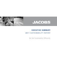
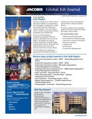
Tail gas from the SRU incinerator, or<br />
waste heat boiler, enters the scrubber inlet<br />
duct and collides with the circulating scrubber<br />
liquor (see Fig. 2). The liquor is injected<br />
countercurrent to the gas flow through a<br />
large bore, open throat nozzle known as<br />
the reverse jet nozzle. The contact zone<br />
where the gas and liquor collide is referred<br />
to as the froth zone.<br />
The froth zone is an area of high mass<br />
transfer and turbulence where quench and<br />
acid gas absorption take place simultaneously.<br />
The amount of recirculation liquid<br />
required to develop the froth zone is calculated<br />
based on the maximum <strong>process</strong><br />
conditions. The liquid flow is constant,<br />
which means that when the inlet gas flow<br />
decreases, the L/G increases and acid gas<br />
removal efficiency increases.<br />
Compared to packed towers, where<br />
high liquid flow rates can cause flooding,<br />
the <strong>DynaWave</strong> <strong>®</strong> can operate at liquid circulation<br />
rates which are 5 to 7 times normal<br />
packed tower flow rates. This allows the<br />
<strong>DynaWave</strong> <strong>®</strong> to handle extremely high levels<br />
of SO 2 , present at SSM when a portion of<br />
the SRU must be bypassed.<br />
To react with SO 2 , owners prefer to use<br />
sodium based reagents such as caustic<br />
(NaOH). The reaction between SO 2 and caustic<br />
is a strong acid-base reaction and is practically<br />
instantaneous. Once the SO 2 is in<br />
solution, the reaction proceeds as follows:<br />
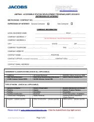
Fig 2: <strong>DynaWave</strong> <strong>®</strong> reverse jet scrubber<br />
effluent<br />
dirty gas in<br />
pump<br />
clean gas out<br />
make-up<br />
SO 2 (v) + NaOH (l) → NaHSO 3<br />
SO 2 (v) + 2NaOH (l) → Na 2 SO 3 + H 2 O<br />
In most cases, the sodium sulphite/<br />
sodium bisulphite salts formed in the<br />
above reactions must be further oxidised<br />
to sodium sulphate in order to reduce the<br />
COD of the scrubber effluent to acceptable<br />
levels. The reactions are as follows:<br />
NaHSO 3(soluble salt) + 0.5O 2 + NaOH →<br />
Na 2SO 4 (soluble salt) + H 2O<br />
Na 2 SO 3 (soluble salt) + 0.5O 2 → Na 2 SO 4<br />
(soluble salt)<br />
After the gas exits the inlet duct, it flows<br />
through the top portion of the vessel and<br />
exits to atmosphere through an integral<br />
stack. Before exiting the vessel, the clean,<br />
saturated gas flows through a set of<br />
chevrons which maximise liquid droplet<br />
removal from the gas stream.<br />
The scrubbing liquor falls to the bottom<br />
of the scrubber vessel which is used as a<br />
reservoir for continuous feed to the recirculation<br />
pumps. The vessel also provides<br />
the oxidation zone for in-situ oxidation of<br />
sulphite salts to sulphate salts.<br />
The <strong>DynaWave</strong> <strong>®</strong> wet gas scrubber has<br />
been installed in over 300 applications<br />
worldwide. The <strong>DynaWave</strong> <strong>®</strong> has been designed<br />
for 11 SRU tail gas treatment projects in the<br />
United States, and installed in seven. The<br />
<strong>DynaWave</strong> <strong>®</strong> is leading all other SO 2 absorption<br />
technologies in total SRU installations.<br />
<strong>SUPERCLAUS</strong><strong>®</strong>/<strong>DynaWave</strong><strong>®</strong> <strong>process</strong><br />
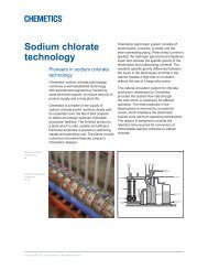
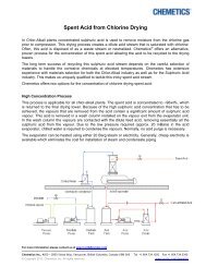
By combining the <strong>SUPERCLAUS</strong> <strong>®</strong> and<br />
<strong>DynaWave</strong> <strong>®</strong> technologies, the overall system<br />
can achieve greater than 99.9% sulphur<br />
removal at compelling capital and operating<br />
costs. Approximately 99.0% of the H 2 S is<br />
captured and recovered as elemental sulphur<br />
by the <strong>SUPERCLAUS</strong> <strong>®</strong> and the remaining<br />
sulphur is scrubbed and converted to<br />
Na 2 SO 4 by the <strong>DynaWave</strong> <strong>®</strong> . Figure 3 is a<br />
schematic of the combined technologies:<br />
Technology comparison<br />
When comparing <strong>SUPERCLAUS</strong> <strong>®</strong> /<strong>DynaWave</strong> <strong>®</strong><br />
with an amine-based TGTU, one must fully<br />
assess the advantages or disadvantages<br />
of each factor, e.g. capital costs, operating<br />
costs, number of equipment items, plot<br />
foot-print, liquid discharges, chemical<br />
requirements, achievable sulphur recovery<br />
rate and operability/reliability.<br />
2 Sulphur 326 | January-February 2010
Fig 3: Combined <strong>SUPERCLAUS</strong> <strong>®</strong> / <strong>DynaWave</strong> <strong>®</strong> <strong>process</strong><br />
SO 2 emissions<br />
waste heat<br />
boiler<br />
air<br />
feed gas<br />
steam<br />
combustion<br />
chamber<br />
condenser<br />
The basis of the comparison assumes an<br />
EPA stack SO 2 outlet limit of 50 ppm. Both<br />
technology offerings can achieve greater<br />
than 99.9% removal of the sulphur and discharge<br />
less than 50 ppm SO 2 at their<br />
respective outlets.<br />
To achieve this low SO 2 outlet value,<br />
the amine-based TGTU normally requires an<br />
amine additive to allow for very lean<br />
solvent stripping. Also required are additional<br />
trays in the towers, as well as increased<br />
solvent circulation and reboiler duties.<br />
The <strong>SUPERCLAUS</strong> <strong>®</strong> /<strong>DynaWave</strong> <strong>®</strong> option<br />
achieves low SO 2 emission levels simply<br />
through the combination of the two technologies.<br />
The <strong>SUPERCLAUS</strong> <strong>®</strong> <strong>process</strong> uses<br />
proprietary selective oxidation catalyst to<br />
reduce tail gas SO 2 levels to 1,600 ppm.<br />
The <strong>DynaWave</strong> <strong>®</strong> scrubber takes the incinerated<br />
tail gas and reduces its SO 2 content<br />
from 1,600 ppm to 50 ppm or less.<br />
Comparative capital costs<br />
A capital cost analysis was performed<br />
based on a 140 t/d sulphur recovery<br />
facility <strong>process</strong>ing acid gas containing 77<br />
mol-% H 2S and 8 mol-% NH 3. For both the<br />
amine-based TGTU and <strong>SUPERCLAUS</strong> <strong>®</strong> /<br />
<strong>DynaWave</strong> <strong>®</strong> <strong>process</strong>, costs were calculated<br />
on a “turnkey” installed basis and include<br />
+<br />
reheater<br />
steam<br />
S<br />
S<br />
ABC control<br />
system<br />
<strong>SUPERCLAUS</strong><strong>®</strong><br />
Claus reactor selective oxidation reactor<br />
incinerator<br />
S<br />
H 2 S<br />
QC<br />
all auxiliary equipment such as waste heat<br />
boilers, incinerators, stacks, amine/<br />
caustic storage tanks, drain tanks, pumps,<br />
scrubbers, etc. Costs for catalyst,<br />
chemicals, royalties, etc. were also<br />
included for a more comprehensive<br />
comparison. No costs were included for<br />
sulphur storage or handling facilities.<br />
Table 1 provides a comparison of the<br />
relative capital costs. In each case a grass<br />
roots installation is assumed and a thermal<br />
stage followed by a two-stage Claus<br />
unit is included. Normalising the SRU plus<br />
amine-based TGTU system cost to a relative<br />
value of 185, the combined SUPER-<br />
CLAUS <strong>®</strong> /<strong>DynaWave</strong> <strong>®</strong> <strong>process</strong> cost is only<br />
140. This indicates an overall 24% capital<br />
cost savings when choosing the SUPER-<br />
CLAUS <strong>®</strong> /<strong>DynaWave</strong> <strong>®</strong> <strong>process</strong>.<br />
When a two-stage Claus unit already<br />
exists and a TGTU is to be added, the evaluation<br />
shows that the <strong>SUPERCLAUS</strong> <strong>®</strong> /<br />
<strong>DynaWave</strong> <strong>®</strong> <strong>process</strong> provides approximately<br />
53% savings on the capital cost of<br />
an amine-based TGTU. Most of the savings<br />
are realised through a simpler flow<br />
scheme, less complex equipment (fewer<br />
towers and pumparounds) and approximately<br />
35% less equipment count.<br />
Savings will depend on the size of the<br />
SRU system, however, it is reasonable to<br />
assume that the cost advantage of the<br />
CLAUS TAIL GAS TREATING<br />
<strong>SUPERCLAUS</strong> <strong>®</strong> /<strong>DynaWave</strong> <strong>®</strong> <strong>process</strong> will<br />
hold for a wide range of sulphur loads.<br />
Operational/equipment complexity<br />
Simplicity of operation and equipment<br />
complexity are key considerations when<br />
choosing a <strong>process</strong> to install. Compared to<br />
an amine-based TGTU, the <strong>SUPERCLAUS</strong> <strong>®</strong> /<br />
<strong>DynaWave</strong> <strong>®</strong> <strong>process</strong> has 35% less<br />
equipment and fewer complex equipment<br />
items because complex towers with<br />
pumparound systems are not required.<br />
The <strong>SUPERCLAUS</strong> <strong>®</strong> /<strong>DynaWave</strong> <strong>®</strong> <strong>process</strong><br />
essentially requires a reheater, reactor,<br />
sulphur condenser and caustic scrubber.<br />
This translates into less maintenance costs,<br />
less operational attention and manhours<br />
and the probability of a higher on-stream<br />
factor if equipment redundancy is equivalent.<br />
Plot footprint<br />
A factor that is sometimes overlooked<br />
when comparing technologies is the plot<br />
footprint required of the installation.<br />
The <strong>SUPERCLAUS</strong> <strong>®</strong> /<strong>DynaWave</strong> <strong>®</strong> <strong>process</strong><br />
requires approximately 40% less plot<br />
space than the amine-based TGTU. The<br />
equipment count is 24 for an amine-based<br />
TGTU compared to 16 for <strong>SUPERCLAUS</strong> <strong>®</strong> /<br />
<strong>DynaWave</strong> <strong>®</strong> . The SRU section with two reactors<br />
common to both <strong>process</strong> schemes<br />
has 23 pieces of equipment.<br />
Sulphur 326 | January-February 2010 3<br />
FC<br />
S<br />
caustic<br />
<strong>DynaWave</strong><strong>®</strong><br />
outlet<br />
make-up<br />
blowdown
CLAUS TAIL GAS TREATING<br />
Comparative operating costs<br />
Comparative operating costs, i.e. utilities,<br />
can be broken down into several categories;<br />
power, steam, fuel gas, water, and<br />
chemicals. For a 140 t/d SRU, Table 2 provides<br />
a utility cost comparison between an<br />
amine-based TGTU and a <strong>SUPERCLAUS</strong> <strong>®</strong> /<br />
<strong>DynaWave</strong> <strong>®</strong> .<br />
As Table 2 illustrates, there is approximately<br />
20% operating cost savings with the<br />
<strong>SUPERCLAUS</strong> <strong>®</strong> /<strong>DynaWave</strong> <strong>®</strong> Process.<br />
The <strong>SUPERCLAUS</strong> <strong>®</strong> /<strong>DynaWave</strong> <strong>®</strong> <strong>process</strong><br />
typically does not require cooling water<br />
because the only cooling needed is to<br />
condense the steam from the final sulphur<br />
condenser. The amine-based TGTU requires<br />
2,050 gpm of cooling water for a 140 t/d SRU.<br />
With regards to overall fresh water<br />
make-up, the <strong>SUPERCLAUS</strong> <strong>®</strong> /<strong>DynaWave</strong> <strong>®</strong><br />
<strong>process</strong> will consume 18.5 gpm. This is<br />
the amount of water required to quench the<br />
gas from the incinerator waste heat boiler<br />
plus any effluent discharged from the<br />
scrubber system. The amine-based TGTU<br />
does not require direct fresh water makeup,<br />
but Table 2 takes into consideration<br />
water evaporated in the cooling tower.<br />
The <strong>SUPERCLAUS</strong> <strong>®</strong> /<strong>DynaWave</strong> <strong>®</strong> <strong>process</strong><br />
requires caustic to react with the 1,600<br />
ppm SO 2 from the incinerator waste heat<br />
boiler. The amount of caustic required by<br />
the <strong>SUPERCLAUS</strong> <strong>®</strong> /<strong>DynaWave</strong> <strong>®</strong> <strong>process</strong> is<br />
in the order of 3.5 long t/d, dry basis for a<br />
140 t/d sulphur <strong>process</strong>ing facility. The<br />
reaction products result in a 10 gpm liquid<br />
effluent stream that contains 10% sodium<br />
sulphate which is typically sent to the<br />
waste water treatment plant.<br />
The amine-based TGTU <strong>process</strong> effluent<br />
is a 17 gpm waste water stream, containing<br />
20-50 ppm H 2 S, which requires further<br />
treatment before being sent to the waste<br />
water treatment plant.<br />
Table 2: Utility comparison (140 t/d SRU)<br />
Table 1: Technology capital cost comparison (140 t/d SRU)<br />
Item Unit description Relative Approximate Comparison<br />
cost savings (%) basis<br />
1 2-Stage Claus SRU 100<br />
2 2-Stage Claus SRU + amine-based TGTU 185<br />
3 2-Stage Claus SRU +<br />
<strong>SUPERCLAUS</strong><strong>®</strong> /<strong>DynaWave</strong><strong>®</strong><br />
140 24% Item 3 vs 2<br />
4 Amine-based TGTU alone 85<br />
5 <strong>SUPERCLAUS</strong><strong>®</strong> / <strong>DynaWave</strong><strong>®</strong> alone 40 53% Item 5 vs 4<br />
Unique SRU solutions<br />
Sometimes an owner does not require a<br />
complete TGTU. This might be the case<br />
when the Claus SRU is small or another<br />
TGTU technology is already installed. Both<br />
<strong>SUPERCLAUS</strong> <strong>®</strong> and <strong>DynaWave</strong> <strong>®</strong> offer solutions<br />
even in this situation.<br />
Reducing Claus unit operating costs<br />
For example, some owners have installed<br />
caustic scrubbers, such as the <strong>DynaWave</strong> <strong>®</strong> ,<br />
directly after their Claus units. This has<br />
allowed them to meet air permit requirements<br />
without installing complete aminebased<br />
TGTUs.<br />
When caustic is expensive, the operating<br />
costs of an inefficient Claus unit followed by<br />
a caustic scrubber can be high. The SUPER-<br />
CLAUS <strong>®</strong> <strong>process</strong> offers a solution with the<br />
simple retrofit addition of <strong>SUPERCLAUS</strong> <strong>®</strong> catalyst<br />
into the third Claus reactor and possibly<br />
a new sulphur condenser for the<br />
additional heat load generated by SUPER-<br />
CLAUS <strong>®</strong> . If the 3rd Claus stage does not<br />
exist, then the addition of a new SUPER-<br />
CLAUS <strong>®</strong> stage would be required.<br />
SRU <strong>process</strong> unit redundancy<br />
In the future, <strong>process</strong> units may no longer<br />
be able to exempt emissions excesses dur-<br />
ing startup, shutdown and malfunction<br />
(SSM). Emission levels during SSM are<br />
potentially unpredictable. In the case of<br />
SRUs with TGTUs, normal emissions can be<br />
between 200-1000 ppm SO 2 . During SSM,<br />
emissions can reach 4,000 to 10,000 ppm<br />
SO 2 or even higher, and gas flow rates can<br />
fluctuate as well. The technology that follows<br />
the SRU must be able to handle this wide<br />
range of <strong>process</strong> variables. As explained previously,<br />
one of the major advantages of the<br />
<strong>DynaWave</strong> <strong>®</strong> scrubber is its capability to handle<br />
very wide turndown operations.<br />
New requirements for very low SO 2<br />
emissions<br />
Typical emission requirements for SRUs in<br />
the United States range between 50 to 250<br />
ppm. The Air Quality Management District<br />
in Los Angeles, California is investigating<br />
the feasibility of limiting SO 2 emissions to<br />
below 10 ppm. The <strong>DynaWave</strong> <strong>®</strong> is a robust<br />
and reliable wet gas scrubbing <strong>process</strong><br />
which can meet these future emission<br />
requirements at a reasonably low operating<br />
cost. In addition, since many owners will be<br />
required to retrofit a wet gas scrubber into<br />
an existing facility, the small footprint of the<br />
<strong>DynaWave</strong> <strong>®</strong> provides the possibility to<br />
install this technology where real estate is<br />
at a premium. ■<br />
Amine-based TGTU <strong>SUPERCLAUS</strong> <strong>®</strong> /<strong>DynaWave</strong> <strong>®</strong><br />
Utility type $/Unit cost Consumption $/Day cost Consumption $/Day cost<br />
Electric power $.08/kWh 499 kW 958 485 kW 931<br />
60 psig steam consumed $4/1000 lb 10,200 lb/hr 979 none 0<br />
60 psig steam produced $4/1000 lb none 0 7,500 lb/hr (produced) -720 (credit)<br />
Fuel gas (incinerator) $3.50/1000 SCF 14,800 SCFH 1,243 16,600 SCFH 1,394<br />
Fuel gas (heater or RGG) $3.50/1000 SCF 3,500 SCFH 294 1,340 SCFH 113<br />
Cooling water $0.10/1000 gal 2050 gpm 295 none 0<br />
Fresh water $1.30/1000 gal 22 gpm 42 18.5 gpm 35<br />
Amine make-up $1.40/ lb 55 lb/day 77 none 0<br />
Caustic make-up $0.175/lb ($350/ton) none 0 7,721 lb/day 1,351<br />
Total $3,888/day $3,104/day<br />
4 Sulphur 326 | January-February 2010