SOLVING TV RECEPTION PROBLEMS - Jaycar Electronics
SOLVING TV RECEPTION PROBLEMS - Jaycar Electronics
SOLVING TV RECEPTION PROBLEMS - Jaycar Electronics

Create successful ePaper yourself
Turn your PDF publications into a flip-book with our unique Google optimized e-Paper software.
<strong>Jaycar</strong> <strong>Electronics</strong> Tech Update: <strong>TV</strong>RECEPT.PDF (1)<br />
<strong>SOLVING</strong> <strong>TV</strong> <strong>RECEPTION</strong> <strong>PROBLEMS</strong><br />
Not happy with your <strong>TV</strong> reception? Most <strong>TV</strong> reception problems can be solved, or at<br />
least minimised, providing you tackle them the right way. You have to know what<br />
you’re doing though, or you can easily spend a fair bit of time and money making things<br />
wwoorrssee, rather than better!<br />
Ask many people what causes poor <strong>TV</strong> reception, and<br />
they’ll say they’re due to weak signals from the <strong>TV</strong><br />
stations. As a result the first thing that people often do,<br />
when they get poor <strong>TV</strong> reception, is go out and buy an<br />
expensive masthead amplifier to ‘boost’ the signals.<br />
Then 8 times out of 10 they become very unhappy when<br />
they discover that their new masthead amp either makes<br />
no difference, or actually makes the reception WORSE.<br />
The truth is that low signal strength or ‘weak signals’<br />
are the cause of only one kind of poor reception, as<br />
we’re going to explain shortly. And this kind of poor<br />
reception really only occurs in about 15-20% of cases;<br />
the other 80 - 85% of cases are due to other things like<br />
signal overload, electromagnetic interference or<br />
‘ghosting’ (multipath reception).<br />
With these other more common causes of poor<br />
reception, boosting the signal strength with a masthead<br />
amp can easily make the problem worse rather than<br />
better. And even though a masthead amp can at times<br />
help when poor reception IS due to weak signals, this is<br />
generally NOT the first line of attack. In most cases<br />
you’ll achieve much more improvement by changing to a<br />
higher gain antenna, as we’ll explain soon.<br />
In this Tech Note we’re going to help you avoid<br />
making expensive and frustrating mistakes by explaining<br />
the basics of <strong>TV</strong> reception and the various kinds of<br />
problems that can occur. We’re also going to explain<br />
how to diagnose the symptoms for each type of<br />
reception problem, and then how to go about solving<br />
them. With this information under your belt you should<br />
be able to solve most reception problems quickly,<br />
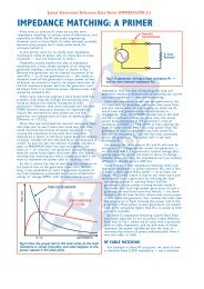
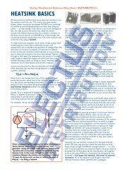
Fig.1: The radio waves from each <strong>TV</strong> station radiate<br />
from its transmitting antenna evenly throughout the<br />
station’s service area. As they do, they spread out<br />
and therefore get weaker with distance...<br />
confidently and with a minimum of cost.<br />
Reception basics<br />
As you might know already, <strong>TV</strong> broadcasting uses<br />
electromagnetic radiation or ‘radio waves’ — just like<br />
AM and FM radio broadcasting, shortwave broadcasting<br />
or even cellular mobile phones. The only difference is<br />
that the waves used for <strong>TV</strong> carry picture information as<br />
well as sound, and have frequencies in channels which<br />
are reserved for <strong>TV</strong> broadcasting in the VHF (very high<br />
frequency) and UHF (ultra high frequency) bands.<br />
At the <strong>TV</strong> station’s transmitter, the video (picture)<br />
and audio (sound) information from the studio is used<br />
to modulate the transmitter’s VHF or UHF carrier<br />
signals, which are then fed up via cables to the<br />
transmitting antennas at the top of the station’s tower.<br />
The antennas are designed to radiate the signals as radio<br />
waves, as evenly as possible around the station’s service<br />
area.<br />
As a result if you put up a receiving antenna in most<br />
parts of the receiving area, it should be able to pick up<br />
enough energy from the radiated waves to generate<br />
electrical signals which are strong enough to feed into<br />
the antenna input of your <strong>TV</strong> set, so that it can<br />
demodulate them to recreate that station’s pictures and<br />
sound with excellent quality. That’s the ideal, anyway.<br />
So why doesn’t this always happen? There are quite a<br />
few reasons, and to understand them you need to know<br />
a bit more about radio waves — and in particular those<br />
with frequencies in the VHF and UHF bands.<br />
For a start, the waves which radiate away from the <strong>TV</strong><br />
station’s transmitting antennas travel most easily in dry<br />
air, and in paths that are very close to a straight line.<br />
Even in dry air they do gradually become weaker with<br />
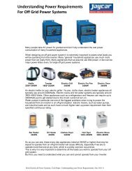
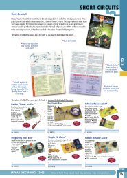
A fairly high gain <strong>TV</strong> antenna, the <strong>Jaycar</strong> LT-3142.<br />
It has 7 longer elements for VHF reception, and<br />
12 shorter elements for UHF reception. This one<br />
is shown facing directly to the left, by the way.
distance, because of the way they are steadily spreading<br />
out as they radiate away (see Fig.1). But providing<br />
there’s a reasonably clear ‘line of sight’ between your<br />
receiving antenna and the transmitter tower, and<br />
you’re no more than about 30km or so from it,<br />
they’re still likely to be strong enough for good<br />
reception in most conditions — using a decent<br />
outdoor antenna, at least.<br />
At these frequencies, though, radio waves do<br />
become much weaker passing through solid<br />
objects like earth, rock, buildings or a lot of<br />
foliage. They also become weaker passing<br />
through water — such as heavy rain. So if you<br />
and your <strong>TV</strong> antenna are down in a gully, or<br />
behind a hill or some large buildings, or in a<br />
dense forest, the signals that reach your antenna<br />
might well be weakened enough to cause poor<br />
reception.<br />
This can also happen during a heavy downpour,<br />
even if you do have a clear ‘line of sight’<br />
<strong>Jaycar</strong> <strong>Electronics</strong> Tech Update: <strong>TV</strong>RECEPT.PDF (2)<br />
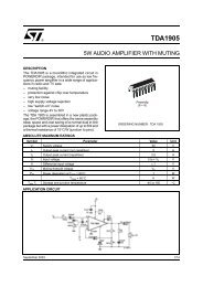
Fig.2: If the signals from a <strong>TV</strong> station are too weak for good<br />
reception, this can be due to a number of causes...<br />
Fig.3: When <strong>TV</strong> signals are too weak for good<br />
reception, this is the kind of picture you get.<br />
This is usually described as an image covered<br />
in ‘snow’, or ‘coloured pepper and salt’.<br />
reception path but are more than about<br />
30km from the transmitter. (Fig.2)<br />
It’s true that low-band VHF signals<br />
(channels 0 - 5A) do ‘bend’ to some extent<br />
around hills and large buildings, so that you<br />
can often get reasonable reception in the<br />
upper ‘shadow’ area behind them. However<br />
further down in a valley, reception may be<br />
very poor.<br />
The screen shot in Fig.3 shows the kind<br />
of reception produced by weak signal<br />
strength. As you can see the picture<br />
becomes ‘snowy’ and covered in specks of<br />
coloured noise, often called ‘pepper and<br />
salt’. There’s a loss in picture detail and<br />
colour saturation, and in severe cases the<br />
picture may lose colour altogether.<br />
We’ll discuss how you can tackle this<br />
sort of problem later. At present, let’s look<br />
at what else can go wrong apart from the<br />
signals becoming too weak for good<br />
reception.<br />
Multipath reception: ghosts<br />
In many ways a much more common<br />
problem is multipath reception, where<br />
signals from the same station can reach<br />
your antenna by two or more distinct paths<br />
which differ significantly in length. This can<br />
happen because VHF and UHF radio waves<br />
can be reflected by large buildings or metal<br />
structures (like bridges), hills and cliff faces,<br />
and even reasonable sized bodies of water<br />
like that in a reservoir, lake or bay.<br />
The waves being reflected by these<br />
objects isn’t in itself a problem. In fact<br />
sometimes reflected signals can be strong<br />
enough for good reception, if you’re in a<br />
location behind a hill or some large<br />
buildings where the direct-path signals are<br />
themselves too weak. (More about this<br />
later.)<br />
The real problem with reflected signals is<br />
when they reach your receiving antenna<br />
along with the direct-path signals, because<br />
when they do they tend to cause unwanted ‘ghost’<br />
images that upset picture clarity.<br />
Can you guess why this happens? It’s because radio
<strong>Jaycar</strong> <strong>Electronics</strong> Tech Update: <strong>TV</strong>RECEPT.PDF (3)<br />
waves travel in air at virtually the same speed as light.<br />
As you might know this is very fast, but still quite<br />
finite. In fact it’s very close to 300,000km/s (kilometres<br />
per second).<br />
So if your receiving antenna is say 10km from a<br />
station’s transmitting tower — line of sight — its<br />
signals will actually be taking 10/300,000 or 33μs (33<br />
millionths of a second) to reach it. Not that you’ll be<br />
aware of this tiny delay, of course. In itself it’s not of<br />
any importance, either.<br />
But this finite speed DOES become important when<br />
reflected signals from the same station can also reach<br />
your antenna — say by reflection from a building, as<br />
shown in Fig.4. Because these reflected signals also<br />
travel at 300,000km/s, but clearly they’re travelling<br />
along a longer path to get to your antenna. This means<br />
that they’ll take slightly longer to get there, arriving<br />
just after the signals which come via the direct path<br />
(which is also clearly the shortest path).<br />
For example in Fig.4, the direct path A might be<br />
10km, but the reflected path B will probably be about<br />
50% longer — say 15km. So the reflected signals will<br />
be travelling an extra 5km, which means they’ll arrive<br />
at your antenna and set about 16μs after the direct<br />
path signals.<br />
As a result, the set will be receiving a mixture of<br />
two distinct versions of the station’s signal, one always<br />
arriving 16μs after the other. So instead of getting just<br />
one picture on the screen, you’ll have two — the main<br />
one (from the direct path) and a weaker one (from the<br />
reflected path). The weaker one will be shifted to the<br />
right, because of the way the <strong>TV</strong> set ‘paints’ the picture<br />
lines from left to right. The second picture is usually<br />
less distinct and more weakly coloured, both because<br />
it’s from a weaker signal and also because of the way the<br />
PAL colour <strong>TV</strong> system used in Australia and New<br />
Zealand works.<br />
But although these extra ‘ghost’ images may be fainter<br />
and more weakly coloured, they can still be quite<br />
distracting and seriously degrade the clarity of your<br />
main picture. That’s why they’re regarded as a reception<br />
problem. An example of a picture with multipath<br />
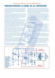
Fig.5: A <strong>TV</strong> picture with multipath reception ghosting. In this<br />
case the second image is a negative, and shifted to the right<br />
of the main image by about 13% of the screen width.<br />
Although pale, it can be quite distracting when the main<br />
image has high-contrast detail...<br />
Fig.4: When signals can reach your antenna by a<br />
reflected path as well as the direct path, this<br />
‘multipath reception’ can cause ghosting because<br />
the reflected signals take longer to reach you.<br />
reception ghosting is shown below in Fig.5.<br />
It can be surprisingly difficult to track down the exact<br />
source of the reflected signal that’s producing a ghost.<br />
However you can at least work out one important point<br />
from a careful inspection of the <strong>TV</strong> screen: how much<br />
further the reflected signal is travelling, compared with<br />
the direct path signal. You do this by carefully measuring<br />
how far the ghost image is to the right of the main<br />
image, as a proportion of total picture width.<br />
The idea behind this is that with the PAL <strong>TV</strong> system<br />
used in Australia and New Zealand, the electron beam<br />
in the picture tube takes exactly 64μs (microseconds) to<br />
‘paint’ each line of the picture. So the full picture width<br />
corresponds to a ‘time ruler’, with a total length of<br />
64μs (Fig.6). Therefore by measuring the separation<br />
between the main and the ghost images, dividing this by<br />
the total picture width and then multiplying<br />
this by 64, you can find the time in<br />
microseconds that the reflected signal is being<br />
delayed compared with the main signal.<br />
For example in Fig.5, the ghost image was<br />
very close to 73mm to the right of the main<br />
image, as measured on a 560mm wide screen<br />
(68cm diagonal). This corresponds to 0.13<br />
(73/560) of the screen width, and 0.13 times<br />
64μs corresponds to 8.3μs. So that’s the time<br />
delay involved in the extra path length for<br />
that particular reflected signal.<br />
Then knowing that radio waves travel at<br />
300,000km/s, or 0.3km/us, it’s easy to work<br />
out the extra path length that results in this<br />
time delay. To find the extra path length in<br />
kilometres, you simply multiply the delay in<br />
microseconds by 0.3:<br />
Px = Td x 0.3<br />
where Px is the extra path length in km and<br />
Td is the reflected signal delay in μs worked<br />
out from the ghost image separation.<br />
So the reflected signal in Fig.5 must be<br />
travelling very close to an extra 2.5km, as 0.3<br />
x 8.3μs = 2.49km.<br />
Another way of working out the extra path<br />
length directly is to remember that because
<strong>Jaycar</strong> <strong>Electronics</strong> Tech Update: <strong>TV</strong>RECEPT.PDF (4)<br />
Fig.6: You can work out how much further the<br />
ghost image signal is travelling, by measuring how<br />
far it’s separated from the main image on the<br />
screen. The screen width represents about 19.2km.<br />
the full screen width represents 64μs, this also<br />
represents 19.2km of extra path length at the speed that<br />
radio waves travel. So if you measure the distance<br />
between the main and ghost images, as a fraction of<br />
total screen width, you can simply multiply this by 19.2<br />
to get the extra path length in km. For our example of<br />
Fig.5, this would mean:<br />
Px = (Dg/Ws) x 19.2 = 0.13 x 19.2 = 2.49km<br />
where Dg is the distance between the main and ghost<br />
images, and Ws is the screen width.<br />
So it’s fairly easy to work out the extra path length<br />
that a reflected signal is travelling, from the on-screen<br />
distance between the ghost image and the main image.<br />
Of course you still have to work out the direction that<br />
the reflected signal is coming from as well, because this<br />
will also determine what you can do the reduce the<br />
impact of the reflected signal. More about this later.<br />
Interference: EMI<br />
Now let’s look briefly at the third main cause of<br />
reception problems: electromagnetic interference (EMI),<br />
also known as radio frequency interference (RFI).<br />
Like multipath reception, EMI is another example of<br />
reception of the signals from your <strong>TV</strong> station(s) being<br />
disturbed by other signals picked up by your antenna.<br />
But instead of the extra signals being reflected and<br />
delayed versions of the main signal, in this case they’re<br />
from a different source of radio waves altogether (see<br />
Fig.7). They might be coming from an industrial heater<br />
or welder; or a medical diathermy machine; or a nearby<br />
computer; or sparking from a big motor drive system<br />
(for lifts or elevators), power tools or appliance motors;<br />
or from corona discharge from high-voltage power lines;<br />
or radiation from a commercial two-way radio<br />
transmitter, CB or amateur radio transmitter. They<br />
might even be from an FM station or another <strong>TV</strong><br />
transmitter on either the same channel as your local<br />
station or an adjoining channel, whose signals are still<br />
able to reach your antenna with sufficient strength to<br />
cause interference.<br />
EMI from FM broadcasting transmitters, industrial<br />
heaters, diathermy machines and computers tends to<br />
cause moving coloured lines or patterns superimposed<br />
on the picture, and again disturbing its clarity. As shown<br />
in Fig.8 the coloured lines are usually slanted, but they<br />
can be at any angle between horizontal and vertical, and<br />
sloping either way. They can also be in a variety of<br />
colours, depending on the exact frequency of the EMI<br />
signal compared to that from the <strong>TV</strong> station.<br />
Some signals from radio transmitters and similar<br />
sources of EMI can also produce audible interference, if<br />
they’re strong enough. This takes the form of beat tones<br />
or ‘whistles’, or garbled and distorted speech, along<br />
with the <strong>TV</strong> programme sound.<br />
EMI from ‘noise’ sources like sparking motors or<br />
corona discharge from power lines tends to produce<br />
horizontal lines or bands of ‘sparkling’ noise<br />
superimposed on the picture, as shown in Fig.8. The<br />
noise bands are often fairly fixed in position vertically,<br />
but they may move slowly up or down. Sometimes the<br />
noise from computers can behave this way too.<br />
Interference from another <strong>TV</strong> station on the same<br />
channel is easy to recognise: like ghosting it manifests as<br />
another picture on the screen, but in this case it’s not<br />
the same picture shifted to the right, but a different<br />
picture altogether. In almost every case it’s not fixed in<br />
position either — instead it moves slowly from left to<br />
right or vice-versa.<br />
Before we leave EMI problems, there one kind of<br />
interference which we haven’t mentioned as yet. That’s<br />
the kind that’s due to signal overload: situations where<br />
one or more of the <strong>TV</strong> signals reaching your set from<br />
the antenna are simply too strong. This can cause the<br />
radio receiver part of the <strong>TV</strong> set to distort the signals<br />
itself, and make them interfere with each other as a<br />
result.<br />
The symptoms of overload can be negative and<br />
unstable pictures, picture ‘tearing’, lines and patterns<br />
across the picture (very similar to other kinds of EMI),<br />
other images moving across the picture you’re trying to<br />
watch, and/or distorted sound. These are the sort of<br />
Fig.7: Electromagnetic interference or EMI is<br />
caused by energy radiating from a different source<br />
like a heater, welder, CB radio or power tool.
problems you’ll tend to get if you’re very close to one<br />
<strong>TV</strong> station’s tower, or very near another high powered<br />
transmitter.<br />
<strong>Jaycar</strong> <strong>Electronics</strong> Tech Update: <strong>TV</strong>RECEPT.PDF (5)<br />
Fig.8: The kind of effect you can get from EMI<br />
caused by a continuous radio signal, such as from a<br />
radio transmitter or diathermy. The coloured lines<br />
can be sloping either way, and at any angle.<br />
Tackling weak signals<br />
Now that you’re aware of the various causes of poor<br />
<strong>TV</strong> reception and the signs to look for in diagnosing<br />
them, we can move forward to look at the best ways of<br />
tackling each problem. We’ll start with weak signal<br />
reception, because this is the type of problem where<br />
many people immediately race off in the wrong direction<br />
(to buy an expensive masthead amp).<br />
Let’s say you’re down in a valley, with a fair-sized hill<br />
blocking your antenna’s view of a station’s transmitter<br />
tower. Or you’re effectively behind a collection of<br />
buildings, or a small forest of trees, which will give much<br />
the same result: weak signals. How do you go about<br />
improving reception in this kind of situation?<br />
Well, the first thing to do is make sure you have a<br />
good outside antenna — at least for the reception of<br />
that particular station. It should also be as high off the<br />
ground as you can mount it, because this will generally<br />
allow it to find stronger signals. That’s why you see <strong>TV</strong><br />
antennas in rural ‘fringe areas’ up on high masts, of<br />
course.<br />
But what exactly is a ‘good’ antenna, I hear you ask?<br />
Basically one that has a high gain — or in other words,<br />
one that is designed to be particularly good at sensing<br />
the presence of passing radio waves, especially those<br />
arriving directly from its front. In fact a high gain<br />
antenna also tends to be very directional, meaning that<br />
it’s very sensitive to signals arriving from the front, but<br />
relatively insensitive to signals arriving from the sides or<br />
from the rear. Another term you’ll see used to describe<br />
this is front-to-back ratio.<br />
Does this sound a bit technical and confusing? It isn’t<br />
really. Just look at Fig.10, which shows how a simple<br />
dipole antenna (the type often used for indoor FM<br />
reception) picks up signals equally well from either side,<br />
and in fact from most directions apart from along its<br />
Right: Another example of a high gain VHF/UHF<br />
antenna, the <strong>Jaycar</strong> LT-3155. It offers considerable<br />
gain on both VHF and UHF channels, as well as a<br />
good front-to-back ratio (i.e., it’s very directional).<br />
This one is ‘pointing’ towards the upper right.<br />
Fig.9: Another kind of EMI, caused by impulse<br />
noise from a power tool or food mixer. Corona<br />
discharge from high voltage power lines can look<br />
similar, but with the noise in horizontal ‘bands’.<br />
own axis at each side. So this is a good example of a<br />
low gain antenna.<br />
Things improve significantly, though, when the<br />
manufacturer adds extra ‘elements’ to the antenna —<br />
usually one or more rods or a metal mesh rectangle<br />
mounted a fixed distance behind the main element<br />
(forming a ‘reflector’) and again one or more shorter<br />
rods at fixed distances in front of the main element (the<br />
‘directors’). These extra elements all have the effect of<br />
reducing the antenna’s sensitivity to waves coming from<br />
the rear and sides, and at the same time boosting its<br />
sensitivity to waves arriving directly from the front.<br />
Broadly speaking the more elements that are added, the<br />
more its front signal-collecting ability and directionality<br />
are improved.<br />
This is all a bit like the way the lenses work in a<br />
telescope or pair of binoculars: they allow us to see<br />
much further directly in front, but they do this by<br />
narrowing our viewing angle.<br />
So high gain <strong>TV</strong> antennas tend to have quite a few<br />
rods and other elements, and they can become quite<br />
large and bulky. But make no mistake: if you’re in a weak<br />
signal area, the most cost-effective way to ensure the<br />
best reception is to use this kind of antenna, mounted<br />
as high as possible. That’s because you’ll be obtaining<br />
the strongest possible signals from the waves coming<br />
from the station(s) it’s pointed at. The signals will also<br />
be accompanied by the least noise and interference as
well, because they tend to be weaker as you<br />
take the antenna higher.<br />
Why can’t you achieve similar results from<br />
a less fancy (i.e., lower gain) antenna, plus a<br />
masthead amplifier? Simply because a lower<br />
gain antenna produces less signal, mixed with<br />
more noise and interference. As a result<br />
when you pass its signals through a masthead<br />
amp to boost the wanted signals, the noise<br />
and interference gets boosted as well. In fact<br />
there’s even more noise and interference<br />
generated in the masthead amp itself, so<br />
there’s actually a small deterioration in<br />
reception rather than an improvement.<br />
This is also why those fancy indoor set-top<br />
antennas with rods, dishes and inbuilt<br />
‘masthead’ amplifiers are really only suitable<br />
for situations where you have very strong<br />
signals and very low noise. In a weak signal<br />
area they simply don’t pick up enough signal,<br />
and too much noise.<br />
So the first and main step in tackling weak<br />
signal problems is to use a high gain antenna,<br />
and mount it up as high as you can.<br />
Of course the main drawback of a high gain<br />
antenna is that it will be very directional —<br />
that’s how its high gain is achieved, after all.<br />
So you’ll have to make sure it’s very carefully<br />
pointed at the station you want, because it<br />
will be very poor at receiving signals from<br />
any other direction.<br />
What if you want to receive weak signals<br />
from a number of stations, and they’re all in<br />
different directions? There are two ways of<br />
solving this one.<br />
<strong>Jaycar</strong> <strong>Electronics</strong> Tech Update: <strong>TV</strong>RECEPT.PDF (6)<br />
You may need a rotator<br />
One approach is to use a single high gain<br />
antenna with a remotely-controlled rotator<br />
system, so you can swing it around to point<br />
to whichever station you want to watch.<br />
Modern rotator systems can have a ‘memory’<br />
which stores the correct bearing for each of<br />
your stations, so they can automatically swing<br />
the antenna to the correct position at the<br />
touch of a button.<br />
The other approach is to have a number of<br />
fixed high gain antennas, each pointing at one<br />
of the stations, and with their signals either selected by<br />
a set-top switch box, or combined using a device called<br />
a diplexer.<br />
Fig.10: As additional elements are added to a basic dipole<br />
antenna (top), it becomes MORE sensitive to signals coming<br />
from directly in front (i.e., its gain increases), and also LESS<br />
sensitive to signals coming from the rear — so it becomes<br />
more directional as well. Both effects make the antenna<br />
more helpful in solving many kinds of reception problem.<br />
This type of rotating or multi-antenna system can get<br />
a bit complicated and expensive, but the results will<br />
always be much better than using a low gain, less<br />
directional antenna with a masthead amplifier.<br />
OK, I hear you ask, what if I am already using a topnotch<br />
high gain antenna, mounted as high as possible,<br />
but my signal strength STILL isn’t strong enough for<br />
good reception. What do I try next?<br />
This can certainly happen, especially in deep fringe<br />
areas, and it is in fact one of the few situations where<br />
you MAY be able to get a worthwhile improvement<br />
using a masthead amplifier. But be warned: it may not<br />
help much, and it may also bring with it some problems<br />
of its own, as we’ll discuss later.<br />
Be aware too that if it’s to give you any real<br />
improvement in reception, a masthead amplifier MUST<br />
Here’s an example of a very high gain, highly<br />
directional antenna for UHF reception only. This is<br />
the <strong>Jaycar</strong> model LT-3182, which has a total of no<br />
less than 91 elements. It’s pointed towards the upper<br />
left, of course (smallest elements to the front).
<strong>Jaycar</strong> <strong>Electronics</strong> Tech Update: <strong>TV</strong>RECEPT.PDF (7)<br />
A diplexer, of the type used to combine signals<br />
from two antennas before sending them down to<br />
the receiver. This one is the <strong>Jaycar</strong> LT-3015, a<br />
masthead unit which combines the signals from<br />
VHF and UHF antennas.<br />
be mounted exactly where its name suggests: right up at<br />
the top of the mast, as close as possible to the antenna.<br />
There’s no point in fitting one down at the bottom of<br />
the mast or next to the <strong>TV</strong> set, because the weak<br />
signals from the antenna will be even weaker by the<br />
time they travel down the antenna cable — which<br />
attenuates signals, but at the same time introduces more<br />
noise.<br />
Two more comments, before we leave the topic of<br />
weak signal problems. In some situations where the<br />
direct-path signals are too weak even when you use a<br />
high gain antenna, there may be stronger reflected<br />
signals coming to you from a different direction — from<br />
a cliff face away to the side, for example. So it’s a good<br />
idea in these situations to try swinging the antenna<br />
around, just to see what kind of reception can be<br />
achieved. Just occasionally the reflected signals can give<br />
better reception — so set your antenna up pointing in<br />
that direction instead.<br />
Another source of alternative signals is UHF repeaters<br />
and translators — ‘relay stations’ which are used to<br />
make the signals from stations available in areas with<br />
known reception problems. So if you still can’t get<br />
acceptable reception of a station on its usual frequency<br />
channel, try looking for the same signal on another<br />
channel in the UHF band.<br />
In the Sydney area, for example, all of the main<br />
stations (both VHF and UHF) are also carried on<br />
repeaters and translators working on channels in the<br />
UHF band. This is also the case in most other<br />
metropolitan areas. As a result if you can’t get a<br />
station’s main signal at acceptable strength, you may still<br />
be able to get good reception via a UHF translator’s<br />
signal.<br />
You can find out the UHF channels used by <strong>TV</strong><br />
translators for the various channels in your area from<br />
the Australian Broadcasting Authority website<br />
(www.aba.gov.au).<br />
Expelling ghosts<br />
The most promising way of tackling poor <strong>TV</strong><br />
reception due to weak signals, then, is to get a high gain<br />
antenna — but what if your problem is ghosts instead?<br />
Surprising though it may seem, a high gain antenna is<br />
still the best way of tackling this type of problem too.<br />
That’s because as we’ve already seen, a high gain<br />
antenna is also very directional. In fact the higher its<br />
gain, the more an antenna responds only to signals<br />
coming from directions which are inside a narrow cone<br />
shape directly in front (Fig.10).<br />
As a ghost image corresponds to a second version of<br />
the signal from the <strong>TV</strong> station, reflected from a large<br />
object and thus arriving via a longer path, this means<br />
that often it’s also arriving from a different direction<br />
(Fig.4). So with a high gain, very directional antenna it’s<br />
often possible to swing the antenna around a little to<br />
the left or right so that it still receives the ‘direct path’<br />
signal at good strength, but picks up very little of the<br />
‘reflected path’ signal that was responsible for the ghost.<br />
This is shown in Fig.11.<br />
Of course this approach can’t help you if the reflected<br />
signal is coming from almost exactly the same direction<br />
as the direct path signal — for example from a source<br />
which is behind the station’s transmitting tower, from<br />
your own antenna’s point of view. But there’s very little<br />
you can do about this type of multipath ghosting anyway<br />
— so it’s just as well this only happens very rarely.<br />
Luckily most ghosts seem to be caused by reflection<br />
from objects at a reasonable distance to one side of the<br />
direct path, so they often respond quite well to using a<br />
very directional antenna as shown in Fig.11.<br />
In really stubborn cases where a single very<br />
directional antenna can’t reject the reflected path signal<br />
enough by itself to ‘lay the ghost’, it’s possible to use a<br />
second very directional antenna to receive the reflected<br />
path signal by itself, and then add this antenna’s signal to<br />
that from the main antenna with the connections<br />
reversed — so the reflected path signal is cancelled out.<br />
This is fairly expensive and can be tricky to set up, but<br />
it’s about the only way to tackle a very troublesome<br />
multipath ghost problem.<br />
Repelling EMI<br />
Now let’s consider the various kinds of <strong>TV</strong> reception<br />
problem cause by EMI, and how you can go about<br />
solving them — or at least minimising them.<br />
Again, if the EMI from the source of your interference<br />
is coming from a different direction to the <strong>TV</strong> station<br />
signals, a high gain and very directional antenna will very<br />
likely let you reduce the amount of EMI picked up, just<br />
Fig.11: The only real way to reduce ghosting is to<br />
use a high gain, highly directional antenna and<br />
swing it away from the source of the reflected<br />
signals, so they’re picked up less efficiently —<br />
while still picking up the main direct path signal<br />
at good strength...
<strong>Jaycar</strong> <strong>Electronics</strong> Tech Update: <strong>TV</strong>RECEPT.PDF (8)<br />
by swinging it a little to the opposite side. So this is<br />
again the first thing to try.<br />
If that doesn’t solve the problem, you may need to try<br />
other approaches as well. For example if the<br />
interference is coming from a transmitter or noise<br />
source with a frequency outside the actual <strong>TV</strong><br />
channel(s) you’re trying to receive, it may be possible to<br />
reduce the EMI by using a rejection or notch filter,<br />
connected ‘inline’ — i.e., series with the antenna cable.<br />
A notch filter is basically a tuned circuit, which can be<br />
adjusted to stop signals in a small range of frequencies<br />
from passing through — while allowing signals of all<br />
other frequencies to pass. So by adjusting the filter to<br />
‘reject’ the signals from your source of EMI, they are<br />
prevented from interfering with the <strong>TV</strong> signals.<br />
If on the other hand the interference is coming from a<br />
transmitter of some kind with a frequency inside one of<br />
the channels you’re trying to receive, a notch filter is<br />
not likely to be able to help. Instead you may have to<br />
use an inline attenuator — a device which lowers the<br />
level of all signals passing through it.<br />
The idea here is that by using an adjustable attenuator<br />
and carefully adjusting its degree of attenuation, you may<br />
be able to reduce the EMI signals to a level where they<br />
cause minimal disturbance to the receiver, while still<br />
leaving the <strong>TV</strong> station signals at a strength high enough<br />
to allow good noise-free reception.<br />
Tackling overload<br />
As we saw earlier, one type of reception problem is<br />
due to overloading, where the <strong>TV</strong> signals interfere with<br />
each other in the ‘front end’ of the receiver itself,<br />
because one or more of the signals from the stations<br />
is/are too strong.<br />
The remedy in this kind of situation depends on<br />
whether the overloading is due to just one very strong<br />
signal (because you’re very close to that transmitter), or<br />
more than one. If only one is too strong, the most likely<br />
solution will probably be to connect an inline notch<br />
filter, and adjust it to largely reject the over-strong<br />
signal. In severe cases, you might also need to fit a<br />
metal shield around the back of the <strong>TV</strong> set itself,<br />
connected to the ‘ground’ side of the set’s antenna<br />
input. (The metal shield should be perforated, so that it<br />
doesn’t block ventilation and make the set overheat.)<br />
Masthead amps have quite specific uses, as we<br />
explain in the text. This one is the GME Kingray<br />
MHW34GP (<strong>Jaycar</strong> LT-3290).<br />
Right: A variable inline<br />
attenuator, of the type<br />
which can be used to<br />
solve signal overload<br />
problems. (LT-3050)<br />
Left: A four-way<br />
signal splitter, used<br />
to share <strong>TV</strong> signals<br />
among a number of<br />
outlets. (LT-3047)<br />
Many notch filters allow you to adjust not only the<br />
tuning of the rejection notch, but its degree of rejection<br />
as well. This allows you to reduce the level of the overstrong<br />
signal just enough to prevent overloading.<br />
If your overloading is being caused by more than one<br />
over-strong signal, you may be able to fit additional<br />
notch filters and adjust each of them to throttle back<br />
one of the offending signals. Or if the signals are ALL<br />
too strong, you may be able to achieve the same result<br />
using an inline attenuator. In this case you’d adjust its<br />
degree of attenuation so that the signals are weakened<br />
just enough to prevent overloading, but still strong<br />
enough for good noise-free reception.<br />
(This is clearly the kind of situation where a masthead<br />
amp will do more harm than good. We need to make<br />
the signals weaker, not stronger.)<br />
When masthead amps ARE used<br />
By this stage, you may well be wondering just where it<br />
IS appropriate to use a masthead amplifier. We’ve<br />
discussed quite a few situations where you shouldn’t try<br />
to use one, so perhaps before we end up it would be a<br />
good idea to clarify just when these misunderstood and<br />
often maligned gadgets ARE likely to help.<br />
First of all, as we saw earlier a masthead amp may well<br />
be able to help in fringe area situations where you’re<br />
already using a very high gain antenna mounted as high<br />
as possible, but the signals it picks up are still not<br />
strong enough for good noise-free reception. So that’s<br />
one important use for them. Just remember that in this<br />
sort of application, the masthead amp must be fitted<br />
right up at the antenna, or it won’t be able to improve<br />
reception much at all.<br />
The only other real use for a masthead amp is in<br />
situations where the signals from a single antenna need<br />
to be shared by a significant number of receivers. An<br />
example is a block of home units or apartments, which<br />
may use a single antenna on the roof to feed signals to<br />
one or more outlets in each unit or apartment.<br />
This type of signal sharing is achieved by passing the<br />
signals through splitters, which use resistor networks to<br />
divide the incoming signals so a proportion of each<br />
signal is fed to every outlet. As a result the splitter<br />
output signals are inevitably weaker than the signals<br />
from the antenna — and if many outlets are involved,<br />
this means that each outlet tends to get much weaker<br />
signals. In fact if there are N outlets, each outlet tends<br />
to get signals which are 1/Nth of the antenna signal<br />
strength. So if there are 4 outlets, each gets a signal<br />
only 1/4th as strong as the signal from the antenna.<br />
Needless to say this can easily make the signals at<br />
each outlet too weak for good reception. But this can<br />
be corrected by using a masthead amplifier to boost the
<strong>Jaycar</strong> <strong>Electronics</strong> Tech Update: <strong>TV</strong>RECEPT.PDF (9)<br />
signal strength from the antenna before it passes<br />
through the splitter system, so that each outlet gets<br />
strong enough signals after the splitting losses.<br />
If the basic signals from the antenna are strong<br />
enough in this type of situation, it’s not even necessary<br />
to have the amplifier right up at the antenna. The amp<br />
can be down near the splitter system — in which case it<br />
becomes an RF distribution amplifier rather than a<br />
masthead amp. But note that this can only be done if<br />
the signals from the antenna itself are strong enough, so<br />
that the amplifier is not being used to make weak signals<br />
strong, but to make strong signals even stronger before<br />
they are divided up by the splitter system.<br />
Actually because strong signals can interfere with each<br />
other in this kind of RF distribution amplifier, many<br />
models are in reality a collection of amplifiers — one<br />
dedicated for each <strong>TV</strong> station signal. The incoming<br />
signals from the antenna are separated by tuned filters,<br />
and then passed through their own amplifier. Then the<br />
outputs from each amplifier and combined again with a<br />
diplexer/multiplexer system, to feed the input(s) on the<br />
splitter system.<br />
Hopefully you can see from this explanation that<br />
masthead and RF distribution amplifiers have quite<br />
specific uses, where they do play an important role. But<br />
apart from these uses, they don’t offer any help in a lot<br />
of ordinary <strong>TV</strong> reception problem situations.<br />
If all else fails...<br />
Let’s end up by addressing one question which you<br />
might still want answered, after reading all of the<br />
foregoing. That is: what do you do if you’re in a really<br />
difficult location, you’ve mounted a really good high gain<br />
directional antenna as high as possible, you’ve carefully<br />
pointed it in the best direction, you’ve tried notch<br />
filters and attenuators and so on, but the reception<br />
STILL isn’t good enough?<br />
In this sort of a situation there’s really only one<br />
remaining solution: subscribe to a cable <strong>TV</strong> or ‘CA<strong>TV</strong>’<br />
service. Virtually all CA<strong>TV</strong> services distribute clean<br />
versions of the local ‘free to air’ <strong>TV</strong> signals over their<br />
cable as well as their own Pay-<strong>TV</strong> programming, so this<br />
will enable you to get the stations at optimum viewing<br />
quality without an antenna at all.<br />
Of course even this may not be an option if you’re<br />
way out in the bush, or in a suburb which isn’t serviced<br />
by a CA<strong>TV</strong> company. In that case you might have to<br />
subscribe to a satellite or microwave Pay-<strong>TV</strong> service<br />
instead, or decide to watch movies on DVD.<br />
But in most cases it should be possible to achieve<br />
very acceptable reception of your local <strong>TV</strong> stations, if<br />
you follow the tips we’ve given you in this Tech Note.<br />
(Copyright © <strong>Jaycar</strong> <strong>Electronics</strong>, 2002)<br />
<strong>TV</strong> Antenna & Reception Glossary<br />
Here’s the meaning of the technical jargon you’re most likely to meet:<br />
Attenuator: A device used to reduce deliberately the level/strength of over-strong signals, to prevent overloading.<br />
Balun: A BALanced-to-UNbalanced transformer, used to ensure a correctly matching connection between an antenna and a cable, or<br />
between a cable and a <strong>TV</strong> receiver. This is important for the best reception quality.<br />
Diplexer: A device used to combine the signals from two receiving antennas, so they can be fed down a single cable to the receiver.<br />
Some diplexers can combine VHF signals and some UHF signals, while others can combine both.<br />
Directional antenna: An antenna which is much more sensitive to radio waves coming from one direction (its ‘front’) than from the<br />
opposite direction (its ‘back’).<br />
Director: A metal rod or other element added to the front of an antenna to improve its gain and directional behaviour.<br />
Direct path: The path via which radio waves travel directly from the <strong>TV</strong> station tower to a receiving antenna.<br />
EMI: Electromagnetic interference — what happens when radio frequency signals from other sources interfere with reception. Visual<br />
symptoms include coloured lines across the picture, horizontal bands of noise specks, and so on.<br />
Fringe area: At a significant distance from the <strong>TV</strong> transmitting towers, the signal strength has deteriorated to a level where a high gain<br />
antenna must be used to get acceptable reception quality. This is known as ‘fringe area reception’.<br />
Front-to-back ratio: The sensitivity of a receiving antenna to signals arriving directly from its front, compared with its sensitivity to<br />
signals arriving directly from the back. Also known as ‘directionality’.<br />
Ghosting: Pale extra images on the <strong>TV</strong> screen and to the right of the main image, caused by the reception of signals reflected from<br />
buildings or other structures, in addition to (and arriving slightly after) the direct path signals.<br />
High gain antenna: An antenna which has particularly high sensitivity to signals arriving from directly in front.<br />
Line-of-sight reception: The ideal situation, where there’s a clear visual path from the <strong>TV</strong> station tower to your antenna.<br />
Masthead amplifier: A wideband RF amplifier designed to boost the strength of signals directly at the receiving antenna.<br />
Multipath reception: When the signals from a <strong>TV</strong> station are reaching your <strong>TV</strong> antenna by two or more paths — i.e., one or more<br />
reflected paths as well as the main direct path. This can result in ghosting.<br />
Notch filter: A small tuneable device which can be used to prevent interfering signals from reaching the antenna input of your <strong>TV</strong> set,<br />
to minimise EMI. It’s tuned to ‘notch out’ or reject the interfering signal, while allowing all other signals to pass through.<br />
Reflected path: An indirect path by which <strong>TV</strong> signals can reach your antenna, after being reflected from a building or bridge, etc.<br />
Reflector: One or more metal rods or a metal mesh, fitted to the back of an antenna to improve its gain and directionality.<br />
Rotator: A motor-driven assembly used to allow an antenna to be ‘pointed’ in various directions as desired, by remote control.<br />
Snow: Visible noise specks on the <strong>TV</strong> screen, due to low signal strength. Also called ‘pepper and salt’.<br />
Splitter: A device used to divide up the signal from a receiving antenna, in order to drive a number of outlets and <strong>TV</strong> sets.<br />
VHF: Very high frequencies, as used by Australian <strong>TV</strong> channels 0 - 12. (From 45 - 230MHz)<br />
UHF: Ultra high frequencies, as used by Australian <strong>TV</strong> channels 27 - 69. (From 526 - 820MHz)<br />
UHF translator: A transmitter operating on a UHF channel, which rebroadcasts the signal from a <strong>TV</strong> station to enhance reception.