Digital Video Broadcasting (DVB); User guidelines for Digital ...
Digital Video Broadcasting (DVB); User guidelines for Digital ...
Digital Video Broadcasting (DVB); User guidelines for Digital ...

You also want an ePaper? Increase the reach of your titles
YUMPU automatically turns print PDFs into web optimized ePapers that Google loves.
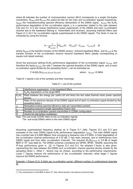
where M indicates the number of communication carriers (M=2 corresponds to a single full-duplex<br />
connection), RDSNG and RCOOR the useful bit-rate <strong>for</strong> the main and co-ordination signals respectively,<br />
ηDSNG the modulation/coding spectral efficiency (bit/symbol) of the DSNG signal, ΔCOOR the Eb/N0<br />
per<strong>for</strong>mance degradation of the co-ordination signal, ρ is a parameter related to the ratio between<br />
C/N and C/I. A is the mutual interference power suppression of the DSNG and each co-ordination<br />
channel due to the baseband filtering in transmitters and receivers, assuming matched filters (see<br />
Figure A.1) (A=1 <strong>for</strong> co-ordination signals superimposed to the DSNG signal). The factor A may be<br />
computed by using the <strong>for</strong>mula:<br />
where HDSNG is the transfer function of the DSNG receive / transmit baseband filters and HCOOR is the<br />
transfer function of the co-ordination receive/ transmit baseband filters (ideally corresponding to<br />
square root raised cosines).<br />
Given the previously defined Eb/N0 per<strong>for</strong>mance degradation of the co-ordination signal ΔCOOR, and<br />
there<strong>for</strong>e the factor ρCOOR, the ratio Γ between the spectral densities of the DSNG signal and of each<br />
co-ordination signal divided by the spreading factor L can be estimated as:<br />
Γ=A/((Eb/N0)COOR ρCOOR ηCOOR) where: ηCOOR =0,9804<br />
Table D.1 reports a list of the symbols and their meanings.<br />
Table D.1. List of the symbols<br />
A Interference suppression in the baseband filters<br />
Δ E b /N 0 degradation at the target BER<br />
1 2<br />
2<br />
= HDSNG(<br />
f)<br />
HCOOR<br />
[ f − ( f0,<br />
DSNG − f0,<br />
)] df<br />
R<br />
Eb/N0 Ratio between the energy per useful bit and twice the two sided thermal noise power spectral<br />
density<br />
Γ Ratio of the spectrum density of the DSNG signal and of each co-ordination signal divided by the<br />
spreading factor L<br />
η Modulation/coding spectral efficiency (bits per transmitted symbol)<br />
L Spreading sequence length (Spreading Factor) (bit)<br />
M Number of co-ordination carriers transmitted in CDMA configuration<br />
R Useful bit-rate be<strong>for</strong>e multiplexer<br />
Note: The sub-script COOR refers to the co-ordination signals<br />
The sub-script DSNG refers to the main DSNG signal<br />
Assuming superimposed frequency sharing as in Figure D.1 (left), Figures D.2 and D.3 give<br />
examples of the main DSNG signal Eb/N0 per<strong>for</strong>mance degradation ΔDSNG. The main DSNG signal<br />
has a symbol rate of 6.666 MBaud, thus occupying a frequency slot of 9 MHz. A fixed degradation of<br />
the co-ordination channel per<strong>for</strong>mance of 4.33 dB ( 1 ) has been imposed, due to interferences from<br />
DSNG signal and from other co-ordination channels. The required (Eb/N0)COOR is 3.6 dB at target<br />
BER of 10 -3 (see table 6). The DSNG schemes considered are QPSK, 8PSK, 16QAM, assuming the<br />
IF-loop per<strong>for</strong>mance given in [2]. In Figures D.2 and D.3, the adopted Γ factor is also given,<br />
representing the ratio between the DSNG and co-ordination channel spectral density divided by the<br />
spreading factor L. Other Γ factors may be chosen, according to the per<strong>for</strong>mance requirements.<br />
Lower Γ figures improve the per<strong>for</strong>mance of the co-ordination channels, while larger Γ figures<br />
improve the DSNG per<strong>for</strong>mance.<br />
Example 1 (Figure D.2): 8 kbit/s per co-ordination carrier, different number of unidirectional channels<br />
M.<br />
( 1 ) This corresponds to a fixed BER of about 10 -5 after Viterbi decoder in the absence of thermal noise<br />
∫ ∞<br />
−∞<br />
A COOR<br />
S<br />
, COOR<br />
29