Digital Video Broadcasting (DVB); User guidelines for Digital ...
Digital Video Broadcasting (DVB); User guidelines for Digital ...
Digital Video Broadcasting (DVB); User guidelines for Digital ...

You also want an ePaper? Increase the reach of your titles
YUMPU automatically turns print PDFs into web optimized ePapers that Google loves.
4.0<br />
3.5<br />
3.0<br />
2.5<br />
2.0<br />
1.5<br />
1.0<br />
0.5<br />
0.0<br />
1/2 2/3 3/4 5/6 7/8 2/3 5/6 8/9 3/4 7/8<br />
QPSK 8PSK 16QAM<br />
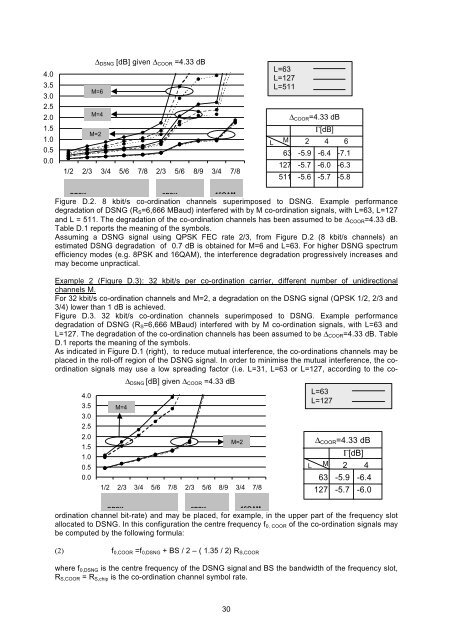
Figure D.2. 8 kbit/s co-ordination channels superimposed to DSNG. Example per<strong>for</strong>mance<br />
degradation of DSNG (RS=6,666 MBaud) interfered with by M co-ordination signals, with L=63, L=127<br />
and L = 511. The degradation of the co-ordination channels has been assumed to be ΔCOOR=4.33 dB.<br />
Table D.1 reports the meaning of the symbols.<br />
Assuming a DSNG signal using QPSK FEC rate 2/3, from Figure D.2 (8 kbit/s channels) an<br />
estimated DSNG degradation of 0.7 dB is obtained <strong>for</strong> M=6 and L=63. For higher DSNG spectrum<br />
efficiency modes (e.g. 8PSK and 16QAM), the interference degradation progressively increases and<br />
may become unpractical.<br />
Example 2 (Figure D.3): 32 kbit/s per co-ordination carrier, different number of unidirectional<br />
channels M.<br />
For 32 kbit/s co-ordination channels and M=2, a degradation on the DSNG signal (QPSK 1/2, 2/3 and<br />
3/4) lower than 1 dB is achieved.<br />
Figure D.3. 32 kbit/s co-ordination channels superimposed to DSNG. Example per<strong>for</strong>mance<br />
degradation of DSNG (RS=6,666 MBaud) interfered with by M co-ordination signals, with L=63 and<br />
L=127. The degradation of the co-ordination channels has been assumed to be ΔCOOR=4.33 dB. Table<br />
D.1 reports the meaning of the symbols.<br />
As indicated in Figure D.1 (right), to reduce mutual interference, the co-ordinations channels may be<br />
placed in the roll-off region of the DSNG signal. In order to minimise the mutual interference, the coordination<br />
signals may use a low spreading factor (i.e. L=31, L=63 or L=127, according to the co-<br />
4.0<br />
3.5<br />
3.0<br />
2.5<br />
2.0<br />
1.5<br />
1.0<br />
0.5<br />
0.0<br />
ΔDSNG [dB] given ΔCOOR =4.33 dB<br />
M=6<br />
M=4<br />
M=2<br />
M=4<br />
ΔDSNG [dB] given ΔCOOR =4.33 dB<br />
ordination channel bit-rate) and may be placed, <strong>for</strong> example, in the upper part of the frequency slot<br />
allocated to DSNG. In this configuration the centre frequency f0, COOR of the co-ordination signals may<br />
be computed by the following <strong>for</strong>mula:<br />
(2) f0,COOR =f0,DSNG + BS / 2 – ( 1.35 / 2) RS,COOR<br />
where f0,DSNG is the centre frequency of the DSNG signal and BS the bandwidth of the frequency slot,<br />
RS,COOR = RS,chip is the co-ordination channel symbol rate.<br />
30<br />
M=2<br />
1/2 2/3 3/4 5/6 7/8 2/3 5/6 8/9 3/4 7/8<br />
QPSK 8PSK 16QAM<br />
L=63<br />
L=127<br />
L=511<br />
L M<br />
ΔCOOR=4.33 dB<br />
Γ[dB]<br />
2 4 6<br />
63 -5.9 -6.4 -7.1<br />
127 -5.7 -6.0 -6.3<br />
511 -5.6 -5.7 -5.8<br />
L=63<br />
L=127<br />
ΔCOOR=4.33 dB<br />
L M<br />
Γ[dB]<br />
2 4<br />
63 -5.9 -6.4<br />
127 -5.7 -6.0