advanced high speed programmable preforming - wiki.ornl.gov ...
advanced high speed programmable preforming - wiki.ornl.gov ...
advanced high speed programmable preforming - wiki.ornl.gov ...

Create successful ePaper yourself
Turn your PDF publications into a flip-book with our unique Google optimized e-Paper software.
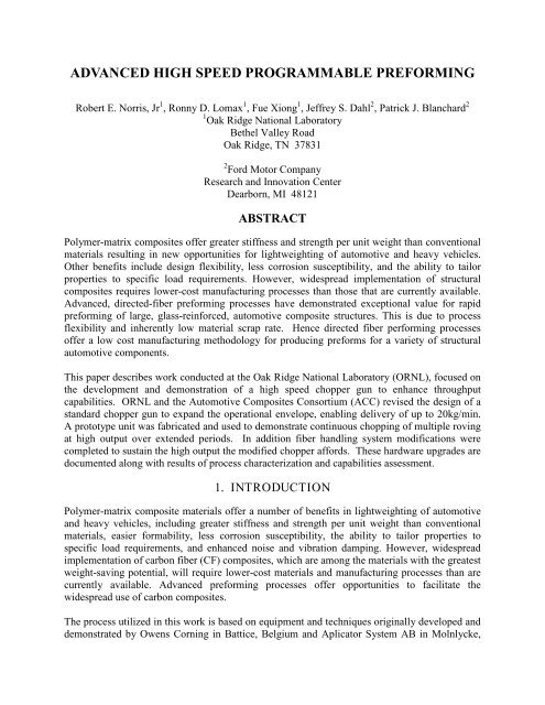
ADVANCED HIGH SPEED PROGRAMMABLE PREFORMING<br />
Robert E. Norris, Jr 1 , Ronny D. Lomax 1 , Fue Xiong 1 , Jeffrey S. Dahl 2 , Patrick J. Blanchard 2<br />
1 Oak Ridge National Laboratory<br />
Bethel Valley Road<br />
Oak Ridge, TN 37831<br />
2 Ford Motor Company<br />
Research and Innovation Center<br />
Dearborn, MI 48121<br />
ABSTRACT<br />
Polymer-matrix composites offer greater stiffness and strength per unit weight than conventional<br />
materials resulting in new opportunities for lightweighting of automotive and heavy vehicles.<br />
Other benefits include design flexibility, less corrosion susceptibility, and the ability to tailor<br />
properties to specific load requirements. However, widespread implementation of structural<br />
composites requires lower-cost manufacturing processes than those that are currently available.<br />
Advanced, directed-fiber <strong>preforming</strong> processes have demonstrated exceptional value for rapid<br />
<strong>preforming</strong> of large, glass-reinforced, automotive composite structures. This is due to process<br />
flexibility and inherently low material scrap rate. Hence directed fiber performing processes<br />
offer a low cost manufacturing methodology for producing preforms for a variety of structural<br />
automotive components.<br />
This paper describes work conducted at the Oak Ridge National Laboratory (ORNL), focused on<br />
the development and demonstration of a <strong>high</strong> <strong>speed</strong> chopper gun to enhance throughput<br />
capabilities. ORNL and the Automotive Composites Consortium (ACC) revised the design of a<br />
standard chopper gun to expand the operational envelope, enabling delivery of up to 20kg/min.<br />
A prototype unit was fabricated and used to demonstrate continuous chopping of multiple roving<br />
at <strong>high</strong> output over extended periods. In addition fiber handling system modifications were<br />
completed to sustain the <strong>high</strong> output the modified chopper affords. These hardware upgrades are<br />
documented along with results of process characterization and capabilities assessment.<br />
1. INTRODUCTION<br />
Polymer-matrix composite materials offer a number of benefits in lightweighting of automotive<br />
and heavy vehicles, including greater stiffness and strength per unit weight than conventional<br />
materials, easier formability, less corrosion susceptibility, the ability to tailor properties to<br />
specific load requirements, and enhanced noise and vibration damping. However, widespread<br />
implementation of carbon fiber (CF) composites, which are among the materials with the greatest<br />
weight-saving potential, will require lower-cost materials and manufacturing processes than are<br />
currently available. Advanced <strong>preforming</strong> processes offer opportunities to facilitate the<br />
widespread use of carbon composites.<br />
The process utilized in this work is based on equipment and techniques originally developed and<br />
demonstrated by Owens Corning in Battice, Belgium and Aplicator System AB in Molnlycke,
Sweden and termed P4, (Programmable Powdered Preforming Process). Aplicator was the<br />
hardware developer and manufactured the research machine for ORNL. In the traditional<br />
embodiment of the process, reinforcing fiber is chopped and sprayed onto a <strong>preforming</strong> screen<br />
along with a powdered binder. The fiber and binder are held in place on the screen by air flow<br />
drawn through the screen by a large suction fan on the opposite side of the screen from the fiber<br />
deposition. In addition to being able to place the chopped fiber and binder where they are of<br />
most benefit structurally via the robot program, one unique aspect of the Aplicator P4 is the<br />
ability to also change the fiber cut length “on-the-fly” by programming variable fiber lengths as<br />
well. Ductwork is then rotated or translated into place over the screen so that air from a<br />
continuously circulating hot air loop can then be directed through the fiber and binder to set the<br />
binder. After exposing the preform to an adequate time at the <strong>high</strong>er temperature, the preform is<br />
cooled, the ductwork removed, and the part extracted. The preform is then moved to a molding<br />
station where Structural Reaction Injection Molding (SRIM) resin is rapidly injected and the<br />
mold closed under pressure to distribute the resin throughout the preform and for consolidation<br />
during final curing. The binder holds the reinforcing fiber in place to maintain the fiber<br />
architecture in handling and during the thermosetting resin injection. This process can achieve<br />
relatively <strong>high</strong> fiber volume fractions with uniform fiber distribution while working with low<br />
cost product forms. Preforming and liquid molding using these processes have been<br />
demonstrated by the Automotive Composites Consortium in its Focal Project 2 pickup truck<br />
box [1] and implemented in limited production for the GMC Silverado and for several parts of<br />
Aston Martin vehicles.<br />
Analyses have indicated a potential for greater than 60% weight savings for a CF-intensive bodyin-white<br />
under the assumption of a thickness design constraint of 1.5 mm. The analyses also<br />
indicated the potential for saving an additional 15% if the thickness constraint is reduced to<br />
1 mm. Unfortunately, evidence suggests that 1.5 mm may be a practical limit for liquid molding<br />
due to resin infiltration difficulties. However, thermoplastic preforms, in which the reinforcing<br />
fiber and matrix (in the form of thermoplastic fiber during deposition) are both deposited in the<br />
<strong>preforming</strong> step, offer a potential path to obtaining thinner sections and, consequently, additional<br />
weight savings as well as greater potential for recyclability. Among other drivers for the use of<br />
thermoplastic materials include reduced cycle times, enhanced damage tolerance, potential<br />
rework with less waste, and fewer resin safety and health issues associated with storage,<br />
handling, and processing of these systems.<br />
One approach to manufacturing thermoplastic composites is to chop and spray the thermoplastic<br />
material in fiber form along with the reinforcing fiber. A product form with commingled glass<br />
and thermoplastic fibers that facilitates this type of processing is a product (Twintex) produced<br />
by Owens Corning Vetrotex. Although the form utilized for this work consists of commingled<br />
glass and polypropylene fibers, the manufacturer has listed other variants and the basic<br />
evaluation process can be extended to a variety of materials and processes based on this concept.<br />
The ACC Materials and Processing working groups has conducted work with Ecole<br />
Polytechnique Federal de Lausanne (EPFL) Laboratory in Switzerland to study processing<br />
effects and material properties leading to cost- model comparisons of various thermoplasticcomposite<br />
processes. With support of EPFL and the ACC, ORNL fabricated approximately 200<br />
sample panels using the polypropylene form of Twintex in various fiber lengths (25 - 75 mm)<br />
and preform thickness (2 mm - 4 mm) along with variations in <strong>preforming</strong> compaction station
time (10-60s) and air temperature (180-240°C). Material properties from the ORNL panels<br />
processed by EPFL are competitive with similar materials and, in some cases, significantly<br />
improved [2-4]. Overall economics for this process were shown by EPFL analysis to approach<br />
targets as chopping <strong>speed</strong>s improve, leading to additional near-term focus on demonstrating the<br />
technical and economic feasibility of <strong>high</strong>er-<strong>speed</strong> chopping processes. This paper discusses<br />
how significantly <strong>high</strong>er chopping <strong>speed</strong>s were achieved and demonstrated [5].<br />
2. CHOPPER EVALUATION AND DEVELOPMENT<br />
2.1 Baseline and Alternative Chopper Hardware<br />
The EPFL analysis indicated economics for thermoplastic <strong>preforming</strong> of a generic liftgate<br />
application (5 kg) in a deposition cycle time of ~30 seconds with this process can be attractive<br />
versus competitive processes such as Glass Mat Thermoplastics (GMT) and Direct Long Fiber<br />
Thermoplastics (D-LFT). This would require fiber deposition rates in the 12 to 15 kg/minute<br />
range using a single deposition head system, leading to our focus on demonstrating the technical<br />
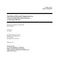
and economic feasibility of <strong>high</strong>er-<strong>speed</strong> chopping processes. For comparison, the baseline P4<br />
chopper as shown in Figure 1 is designed to process 2 tows at up to 625 m/min as supplied by<br />
Aplicator. For the baseline 2400 tex glass fiber for which the machine was designed to process,<br />
this translates to an output of 3,000 g/min and is the machine-rated output. In this work, we are<br />
utilizing the Twintex roving TR PP 60 N 1870, which is a natural color polypropylene with a<br />
60% glass content by weight at 1870 TEX. For this particular roving, processed at the maximum<br />
fiber feed velocity, the material output translates to ~2.3 kg/min. Processing trials determined<br />
the feasibility of running two tows through each tube of the P4 chopper, which effectively<br />
doubled the throughput. However, this rate was difficult to sustain without material jamming<br />
and additional tows could not be added due to physical and motor torque limitations. The P4<br />
chopper allows selection of an infinitely-variable fiber length within a relatively wide range, but<br />
utilization of more than two cut lengths within a single production operation has been very rare.<br />
In order to potentially improve <strong>preforming</strong> throughput, a prototype chopper unit from Wolfangel<br />
Composite Technology in Heimerdingen, Germany was procured. This chopper was designed to<br />
process up to 5 tows at a maximum fiber velocity of ~900 m/min, which for the 1870 TEX<br />
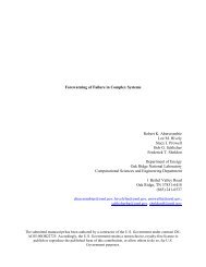
Twintex material translates to a material output of ~8.4 kg/min. The Wolfangel chopper as<br />
shown in Figure 2 affords two distinct fiber lengths determined by blade spacing in either the<br />
inside or outside half of the cutter roll. The positioning of the cutter roll is controlled by<br />
pneumatic actuation; thereby switching the location of the cutter roller with respect to the fibers<br />
and changing the fiber length. Economic goals were to be able to achieve 12 to 15 kg/min,<br />
which would require increasing the number of tows being processed, <strong>speed</strong>ing up the peripheral<br />
<strong>speed</strong>, or combinations of both as described in the following sections.
Figure 1. P4 chopper as supplied by Aplicator. Housings with Aplicator identification<br />
enclose servos for feeding and chopping fiber tows with variable cut lengths.<br />
Figure 2. Wolfangel Chopper showing cutter wheel extended. Cutting takes place<br />
on inner portion of the wheel in contact with the rubber roller.
2.2 Alternative Chopper Evaluation<br />
Trials were conducted to evaluate the chopper using the supplied manual chopper controls and to<br />
capture representative chopper-control signals from the P4 machine to approximate simulation of<br />
the fabrication of a preform suitable for fabrication of an ~5kg liftgate structure similar in shape<br />
to that shown in Figure 3. In typical processing, the chopper starts and stops very abruptly in<br />
tight coordination with the robot movement as the robot traverses across each pass and then<br />
indexes though multiple passes in uniformly spraying up the part profile. Obviously, the<br />
economics of the process are improved as <strong>speed</strong> of the <strong>preforming</strong> process is increased up to the<br />
repeatability and mechanical-loading capabilities of the <strong>preforming</strong> system. A program was<br />
written in LabView to capture representative control signals from the robot that could then be<br />
used to control the chopper for evaluation independent of operation of the entire <strong>preforming</strong><br />
system. A separate LabView program was written to provide necessary control signals to the<br />
chopper using the data previously captured and manipulated into the necessary format for<br />
LabView control, as shown in Figure 4. Also, hardware and program capability was provided to<br />
automatically switch fiber length during processing.<br />
Figure 3. Approximate liftgate dimensions utilized in simulation program.<br />
Figure 4. Chopper control signals in simulation program.
A larger set of trials was conducted at ORNL with ACC support to evaluate the Wolfangel<br />
chopper simulating the liftgate fabrication. During these trials, a number of enhancements were<br />
made to processing conditions, including fiber ejection at the chopper as shown in Figure 5, and<br />
other fiber handling equipment (as described in more detail in a later section). It was determined<br />
that the chopper could easily handle up to 3 tows at close to the upper <strong>speed</strong> limit (900 m/min) to<br />
deliver about 5.0 kg/min, but that the chopper motor stalled and did not have adequate torque to<br />
handle more tows due to the pressure required to fully sever the tows. The system was supplied<br />
with capability to meter 4 bar of pneumatic actuation pressure to the rubber roller/cutter wheel<br />
interface and we found it necessary to operate at or slightly above this level to achieve adequate<br />
severing at the upper levels of output. However, it appeared that achieving both <strong>high</strong>er <strong>speed</strong>s<br />
and <strong>high</strong>er torque with a larger motor would be feasible with relatively minor modifications.<br />
Figure 5. Photo during ORNL/ACC trials showing enhanced fiber ejection.<br />
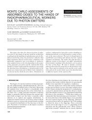
The existing Servowatt motor was rated at 0.75 Newton(N)-m maximum torque and 4,000<br />
revolutions per minute (rpm). An Allen Bradley MPL-B430 motor and drive system was located<br />
that was rated at 20 N-m maximum torque and 5,000 rpm. With this motor operating at its <strong>speed</strong><br />
rating, it should be able to achieve 12 kg/min utilizing about 6 tows with a maximum output of<br />
over 18 kg/min utilizing 9 tows. The system was reconfigured with the new motor while<br />
utilizing as much of the existing chopper hardware as possible as shown in Figure 6, although a<br />
number of components had to be modified in order to utilize this physically larger and <strong>high</strong>erpowered<br />
motor system.<br />
The chopper system was upgraded and then the system was characterized and conditions<br />
tweaked in extensive trials throughout a wide rage of potential operating <strong>speed</strong> ranges while<br />
mounted on the test stand. Initial trials approached output targets, but the chopper motor/head<br />
interface was inadequate for the <strong>high</strong>er torque and additional side loading added to increase the<br />
cutter/roller interface pressures beyond the original allowance for 4 bar actuating pressure,
esulting in hardware failure. The insufficient hardware was upgraded and subsequent detailed<br />
experiments were conducted at operating <strong>speed</strong>s from 30-100% of maximum cutter velocity<br />
utilizing several tow number variations from 3 to 9, a range of cutter actuation pressures from 4-<br />
10 bar, and fiber cut lengths of 25 mm and 75mm while mounted on the test stand. These trials<br />
demonstrated the chopper to be capable of achieving more than 18 kg/min output when using 9<br />
tows and the representative programming conditions described previously. As shown in Table 1,<br />
good severing quality was achieved at these conditions when using 10 bar air pressure on the<br />
cutter/rubber roller interface for the 25mm cut length, while the 75mm length at these conditions<br />
was largely, but not completely, cut. This trend toward better cutting at the shorter length was<br />
essentially replicated for all conditions at which any difference was noted. As expected,<br />
improved severing was achieved at <strong>high</strong>er air pressures for essentially all <strong>speed</strong>s (not shown)<br />
regardless of the number of tows being processed. Also expected was the finding (also not<br />
shown) that cutting quality decreased with increasing the number of tows being simultaneously<br />
cut. However, we somewhat unexpectedly found that cutting quality actually improved with<br />
increased <strong>speed</strong> regardless of the number of tows being cut or interface pressure. When we could<br />
not achieve complete tow severing, typically the glass fibers were completely or largely cut<br />
while the polypropylene was typically the material not fully cut. This is not considered a<br />
significant issue as the polypropylene is actually melted and flows to become the composite<br />
matrix in subsequent operations. Since cutting quality was definitely improved at <strong>high</strong>er <strong>speed</strong>s<br />
while somewhat decreased with larger numbers of tows, it is clear that for a given output target<br />
that one would attempt to run at <strong>speed</strong>s approaching the upper end of the chopper capabilities<br />
and run with the fewest numbers of tows necessary to achieve that output. It is worth noting that<br />
this was achieved with the chopper mounted on a stationary test stand with the distance from<br />
fiber spools to chopper significantly shorter than would be the case for operation on the robot.<br />
As discussed in more detail later, <strong>high</strong>er velocities coupled with rapid stops and starts required to<br />
maximize overall deposition rate create issues with managing tow inertia that are exacerbated as<br />
the distance from spool to chopper is increased. Table 2 shows chopper output as a function of<br />
the number of tows of the Twintex product and percentage of motor capacity.<br />
Figure 6. Wolfangel Chopper with upgraded Allen Bradley Motor.
Table 1. Tow cut quality as a function of number of tows being cut, cut length, and chopper<br />
output. To be considered good, essentially all reinforcing fiber is severed and only small,<br />
isolated amounts of polypropylene are not completely severed.<br />
Output # of Tows →<br />
3 5 7 9<br />
% Cut Length → 25mm 75mm 25mm 75mm 25mm 75mm 25mm 75mm<br />
Poor x x<br />
Needs Improvement x x<br />
30 Marginal x<br />
Acceptable x<br />
Good x x<br />
Poor x<br />
Needs Improvement x x<br />
50 Marginal<br />
Acceptable x x<br />
Good<br />
Poor<br />
x x x<br />
Needs Improvement x x<br />
70 Marginal x<br />
Acceptable x<br />
Good<br />
Poor<br />
x x x x<br />
Needs Improvement x<br />
90 Marginal<br />
Acceptable x<br />
Good<br />
Poor<br />
x x x x x x<br />
Needs Improvement x<br />
100 Marginal<br />
Acceptable x<br />
Good x x x x x x<br />
Tests run at 10 bar roller/cutter interface actuation pressure<br />
Table 2. Chopper output and velocity as a function of motor <strong>speed</strong> and number of tows.<br />
Output Speed Velocity 1 Tow 2 Tows 3 Tows 4 Tows 5 Tows 6 Tows 7 Tows 8 Tows 9 Tows<br />
% RPM m/min kg/min kg/min kg/min kg/min kg/min kg/min kg/min kg/min kg/min<br />
5% 250 56<br />
10% 500 112<br />
15% 750 167<br />
20% 1000 223<br />
25% 1250 279<br />
30% 1500 335<br />
35% 1750 390<br />
40% 2000 446<br />
45% 2250 502<br />
50% 2500 558<br />
55% 2750 613<br />
60% 3000 669<br />
65% 3250 725<br />
70% 3500 781<br />
75% 3750 837<br />
80% 4000 892<br />
85% 4250 948<br />
90% 4500 1,004<br />
95% 4750 1,060<br />
100% 5000 1,115<br />
Chopper out with 1870 tex tows<br />
0.10<br />
0.21<br />
0.31<br />
0.42<br />
0.52<br />
0.63<br />
0.73<br />
0.83<br />
0.94<br />
1.04<br />
1.15<br />
1.25<br />
1.36<br />
1.46<br />
1.56<br />
1.67<br />
1.77<br />
1.88<br />
1.98<br />
2.09<br />
0.21<br />
0.42<br />
0.63<br />
0.83<br />
1.04<br />
1.25<br />
1.46<br />
1.67<br />
1.88<br />
2.09<br />
2.29<br />
2.50<br />
2.71<br />
2.92<br />
3.13<br />
3.34<br />
3.55<br />
3.75<br />
3.96<br />
4.17<br />
0.31<br />
0.63<br />
0.94<br />
1.25<br />
1.56<br />
1.88<br />
2.19<br />
2.50<br />
2.82<br />
3.13<br />
3.44<br />
3.75<br />
4.07<br />
4.38<br />
4.69<br />
5.01<br />
5.32<br />
5.63<br />
5.94<br />
6.26<br />
0.42<br />
0.83<br />
1.25<br />
1.67<br />
2.09<br />
2.50<br />
2.92<br />
3.34<br />
3.75<br />
4.17<br />
4.59<br />
5.01<br />
5.42<br />
5.84<br />
6.26<br />
6.67<br />
7.09<br />
7.51<br />
7.93<br />
8.34<br />
0.52<br />
1.04<br />
1.56<br />
2.09<br />
2.61<br />
3.13<br />
3.65<br />
4.17<br />
4.69<br />
5.21<br />
5.74<br />
6.26<br />
6.78<br />
7.30<br />
7.82<br />
8.34<br />
8.86<br />
9.39<br />
9.91<br />
10.43<br />
0.63<br />
1.25<br />
1.88<br />
2.50<br />
3.13<br />
3.75<br />
4.38<br />
5.01<br />
5.63<br />
6.26<br />
6.88<br />
7.51<br />
8.13<br />
8.76<br />
9.39<br />
10.01<br />
10.64<br />
11.26<br />
11.89<br />
12.51<br />
0.73<br />
1.46<br />
2.19<br />
2.92<br />
3.65<br />
4.38<br />
5.11<br />
5.84<br />
6.57<br />
7.30<br />
8.03<br />
8.76<br />
9.49<br />
10.22<br />
10.95<br />
11.68<br />
12.41<br />
13.14<br />
13.87<br />
14.60<br />
0.83<br />
1.67<br />
2.50<br />
3.34<br />
4.17<br />
5.01<br />
5.84<br />
6.67<br />
7.51<br />
8.34<br />
9.18<br />
10.01<br />
10.85<br />
11.68<br />
12.51<br />
13.35<br />
14.18<br />
15.02<br />
15.85<br />
16.69<br />
0.94<br />
1.88<br />
2.82<br />
3.75<br />
4.69<br />
5.63<br />
6.57<br />
7.51<br />
8.45<br />
9.39<br />
10.32<br />
11.26<br />
12.20<br />
13.14<br />
14.08<br />
15.02<br />
15.96<br />
16.90<br />
17.83<br />
18.77
2.3 Processing Experience Extended to Robot Mounting<br />
This characterization experience was utilized to identify likely fiber handling impediments to<br />
running the Wolfangel chopper on the <strong>preforming</strong> robot at these <strong>high</strong> output <strong>speed</strong>s, and system<br />
improvements have been developed and implemented during the course of this activity. The<br />
<strong>high</strong> <strong>speed</strong>s and large numbers of tows traversing through the system are taxing; more difficult<br />
problems are encountered with the fiber inertia involved with the rapid starting and stopping of<br />
the fiber associated with the robot starting and stopping at the end of each pass. A variety of<br />
changes such as employing a number of hardened fiber guides in the system, utilizing an air<br />
ejection system at the chopper output as previously shown, and the use of funnels to manage the<br />
fiber “whipping” out of the spool were successfully implemented to mitigate <strong>speed</strong> and inertia<br />
problems. With hardware changes and operational experience, capability to run at target outputs<br />
on this stand for extended time periods was demonstrated.<br />
Taking advantage of this background, system hardware and controls necessary to mount the<br />
upgraded Wolfangel chopper on the robot (Figure 7 and 8) have been completed and the chopper<br />
has now been characterized in making representative liftgate preforms and other test sections.<br />
As previously mentioned, fiber inertia causes problems in working with the chopper mounted on<br />
a stationary stand. These problems are exacerbated with abrupt movements of the robot and<br />
further increased with the number and severity of fiber pathway turns required to reach the<br />
chopper in various positions and also as the length of unsupported spans in the distance between<br />
the fiber spools and the chopper increases. A number of additional changes have been made and<br />
others continue to be implemented to improve the fiber delivery to the robot. Among the<br />
changes are implementation of an “air braking” mechanism developed internally from related<br />
hardware (Figure 9) to maintain tension close to the spools and use of fiber spreading and<br />
ceramic eyelets to guide fibers (Figure 10).<br />
Figure 7. Wolfangel chopper mounted on robot.
Figure 8. Upgraded chopper with air ejection system at the bottom.<br />
Figure 9. Air braking mechanism to mitigate fiber inertia problems.<br />
Figure 10. Fiber guides utilized to provide spacing and to mitigate tangling with 9 tow<br />
deposition.
2.4 Chopper Deposition Uniformity<br />
To understand and demonstrate the capabilities for uniform fiber deposition at <strong>high</strong> output rates,<br />
the chopper has also been evaluated for uniform fiber distribution at various <strong>speed</strong>s taking into<br />
account the rapid stopping and starting required for <strong>high</strong> <strong>speed</strong> deposition. A series of tests were<br />
run assuming that the robot would be depositing a 6-pass pattern (3 passes down and back each<br />
without stopping) over lengths of 0.5m, 1m, and 1.5m. Tests were run at 3 different robot <strong>speed</strong>s<br />
and 3 different chopper output levels corresponding to 50, 75, and 100% of rated capability each.<br />
The amount of material deposited was weighed for each test to judge deposition uniformity.<br />
Actual results from this testing are shown in the Table 3. Table 4 shows the results that would be<br />
expected for all other points normalized to the central data point for the 1.0m section at 75%<br />
chopper <strong>speed</strong> and 75% robot <strong>speed</strong> with the other data calculated by <strong>speed</strong> ratios. The data<br />
differences at each point are shown in Table 5 as a % difference from the expected value. As<br />
might be somewhat expected, there tends to be slightly more fiber deposited than predicted at the<br />
lower chopper <strong>speed</strong>s and slightly less than predicted at the <strong>high</strong>er chopper <strong>speed</strong>s. However,<br />
the trends appear to be mixed versus the robot <strong>speed</strong> as slightly more fiber is deposited at both<br />
<strong>high</strong>er robot and lower chopper <strong>speed</strong>s versus the reverse at both <strong>high</strong>er robot <strong>speed</strong>s and <strong>high</strong>er<br />
chopper <strong>speed</strong>s. No effort has been expended to adjust robot dispenseware programming gains<br />
or other settings to this point.<br />
Table 3. Measured chopper output as a function of chopper <strong>speed</strong> and robot <strong>speed</strong> for 6 passes<br />
over specified section lengths.<br />
Robot Speed 100% 75% 50%<br />
Chopper Speed Section Length Mass Mass Mass<br />
m kg kg kg<br />
100% 1.5 2.656 3.531 5.464<br />
1 1.734 2.325 3.619<br />
0.5 0.860 1.145 1.792<br />
75% 1.5 2.057 2.771 4.193<br />
1 1.334 1.820 2.800<br />
0.5 0.669 0.896 1.389<br />
50% 1.5 1.404 1.886 2.737<br />
1 0.925 1.251 1.829<br />
0.5 0.476 0.617 0.921
Table 4. Predicted chopper output based on scaling chopper and robot <strong>speed</strong>s and normalizing to<br />
the measured output at 75% robot and chopper <strong>speed</strong>s and 1.0 m length.<br />
Robot Speed 100% 75% 50%<br />
Chopper Speed Section Length Mass Mass Mass<br />
m kg kg kg<br />
100% 1.5 2.730 3.640 5.460<br />
1 1.820 2.427 3.640<br />
0.5 0.910 1.213 1.820<br />
75% 1.5 2.048 2.730 4.095<br />
1 1.365 1.820 2.730<br />
0.5 0.683 0.910 1.365<br />
50% 1.5 1.365 1.820 2.730<br />
1 0.910 1.213 1.820<br />
0.5 0.455 0.607 0.910<br />
Table 5. Percentage difference of measured output from Table 3 and predicted output in Table 4.<br />
Robot Speed 100% 75% 50%<br />
Chopper Speed Section Length Mass Mass Mass<br />
m kg kg kg<br />
100% 1.5 -2.7% 3.0% 0.1%<br />
1 -4.7% -4.2% -0.6%<br />
0.5 -5.5% -5.6% -1.5%<br />
75% 1.5 0.5% 1.5% 2.4%<br />
1 -2.3% 0.0% 2.6%<br />
0.5 -2.0% -1.6% 1.8%<br />
50% 1.5 2.9% 3.6% 0.3%<br />
1 1.6% 3.1% 0.5%<br />
0.5 4.6% 1.7% 1.2%
2.5 Liftgate Demonstration<br />
With the combination of the system upgrades and process tweaking as previously described, we<br />
were able to meet the objective of 12-15 kg/min deposition rate and demonstrate capability to<br />
deposit a complete liftgate preform (Figure 11) in the 30 seconds assumed in the earlier process<br />
comparison and economic study. Our capabilities exceed the deposition rate assumed for the<br />
upper limit of a single robot/chopper system and the lower end of a dual system as assumed in<br />
this study. Since the objective of this effort was to demonstrate <strong>preforming</strong> system output level<br />
capability to verify economic model assumptions and at this point not to determine the upper<br />
level output practical, we did not optimize the robot program for the time cycle and have not<br />
attempted to run with more tows to increase this output. Also, since tooling does not exist to do<br />
detailed evaluations of a final part, panels have not been molded from which properties can be<br />
obtained. It is anticipated that further processing <strong>speed</strong> and product property relationships can be<br />
established in follow-on work where tooling would be available. Plans are to demonstrate and<br />
evaluate these relationships in looking at potential applications such as the ACC Focal Project 4<br />
Composite Seat.<br />
Figure 11. Representative unconsolidated liftgate preform.
3. CONCLUSIONS<br />
Capability to uniformly sever and deposit thermoplastic tow preforms has been demonstrated at<br />
output rates exceeding 15 kg/min using a modified chopper prototype mounted on the robotic<br />
<strong>preforming</strong> system at ORNL. This effectively more than triples output previously achievable<br />
with baseline equipment. With the combination of the system upgrades and process tweaking as<br />
previously described, we were able to meet the objective of 12-15 kg/min deposition rate and<br />
demonstrate capability to deposit a complete liftgate preform in the 30 seconds assumed in the<br />
earlier process comparison and economic study. Our capabilities exceed the deposition rate<br />
assumed for the upper limit of a single robot/chopper system as assumed in this study. Without<br />
significant focus to this point on the programming and controls part of the system, this deposition<br />
has also shown to be relatively uniform, varying approximately 5% above and below predictions<br />
in this demonstration effort.<br />
4. PLANNED FUTURE WORK<br />
The ACC Focal Project 4 Composite Seat baseline design utilizes glass fiber with a<br />
polypropylene matrix. Tooling is being procured for molding and testing potential materials<br />
system approaches including the <strong>preforming</strong> approach as described here. ORNL will provide<br />
preforms for evaluation in the seat project manufactured from the current Twintex baseline<br />
material and utilizing the existing <strong>preforming</strong> screens. The first goal is to demonstrate technical<br />
feasibility for this product form for this application before working towards optimizing robot and<br />
chopping <strong>speed</strong>s and preform quantities per cycle specifically related to this application. ORNL<br />
will collaborate with the ACC in evaluating this product form as well as the economics involved<br />
in this process.<br />
Hybrid-fiber preforms that can effectively take advantage of utilizing carbon and glass fibers<br />
together in the same structure offer potential benefit in terms of economics and property<br />
enhancement versus using only glass or carbon fiber independently and may be a good route for<br />
actually introducing more carbon fiber at somewhat lower quantities than necessary for allcarbon<br />
components in automotive applications. Since this process uses reinforcing fibers in<br />
relatively simple and low cost product forms and allows placement of materials in specific<br />
locations as desired for structural optimization, we are evaluating a variety of approaches to<br />
introducing and utilizing hybrid forms in applications that could have significant impact to DOE<br />
goals in lightweighting of vehicles.<br />
5. ACKNOWLEDGEMENTS<br />
This Research sponsored by the U.S. Department of Energy, Assistant Secretary for Energy<br />
Efficiency and Renewable Energy, Office of Vehicle Technologies, as part of the Lightweight<br />
Materials Program. LabView programming was provided by Donald L. Erdman. The authors<br />
would also like to express appreciation for related contributions of others at ORNL, the ACC,<br />
and EPFL.
6. REFERENCES<br />
1. N. G. Chavka and J. S. Dahl, P4: Glass Fiber Preforming Technology for Automotive<br />
Applications”, 44 th International SAMPE Symposium, May 1999.<br />
2. S. T. Jespersen , F. Baudry, D. Schmäh, M. D. Wakeman, V. Michaud, P. Blanchard, R. E.<br />
Norris, J.-A. E. Månson, “Rapid Processing of Net-Shape Thermoplastic Planar-Random<br />
Composite Preforms”, Applied Composite Materials (2009) 16:55–71.<br />
3. S. T. Jespersen , F. Baudry, M. D. Wakeman, V. Michaud, P. Blanchard, R. Norris, J.-A. E.<br />
Månson, “Consolidation of Net-shape Random Fiber Thermoplastic Composite Preforms”,<br />
Polymer Composites, published online March 2009.<br />
4. S. T. Jespersen , F. Baudry, M. D. Wakeman, V. Michaud, P. Blanchard, R. Norris, J.-A. E.<br />
Månson, “Flow Properties of Tailored Net-Shape Thermoplastic Composite Preforms”,<br />
Applied Composite Materials, published online September 2009.<br />
5. M. D. Wakeman, G. Francois, J-A. E Manson, “Cost Modeling of Thermoplastic P4 Process<br />
Technology”, Progress Report1 for the Automotive Composites Consortium, Ecole<br />
Polytechnique Fédérale de Lausanne, April 2006.