TV Cabling Solutions Catalogue, 11954 (2329 KB) - Clipsal
TV Cabling Solutions Catalogue, 11954 (2329 KB) - Clipsal
TV Cabling Solutions Catalogue, 11954 (2329 KB) - Clipsal

Create successful ePaper yourself
Turn your PDF publications into a flip-book with our unique Google optimized e-Paper software.
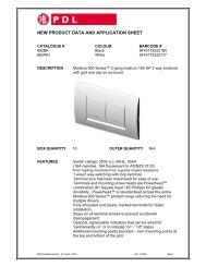
<strong>TV</strong> <strong>Cabling</strong><br />
<strong>Solutions</strong><br />
<strong>Catalogue</strong><br />
When it comes to antenna installation, the choice is clear
Choosing the Right Antenna<br />
The new version of <strong>TV</strong> Across Australia will include<br />
the most up to date planning and implementation<br />
of all analogue and digital broadcast <strong>TV</strong> services<br />
throughout the country.<br />
It will also include an antenna selection for each<br />
transmitter making choosing the right antenna<br />
a very simple exercise. You cannot afford to be<br />
without this great reference guide.<br />
What frequencies are being broadcast in the<br />
location of the installation?<br />
• Every <strong>TV</strong> transmitter Across Australia<br />
• <strong>Clipsal</strong> Antenna part number for every<br />
<strong>TV</strong> transmitter<br />
• Location maps for every <strong>TV</strong> transmitter<br />
Across Australia<br />
• Analogue and Digital <strong>TV</strong> channels broadcast<br />
from every <strong>TV</strong> transmitter<br />
Part Part No: No: 3105<strong>TV</strong>A 3105<strong>TV</strong>A
Contents<br />
4 Terminology<br />
6 MA<strong>TV</strong> basics<br />
10 Antennas<br />
26 Mounting Accessories<br />
38 Splitters<br />
43 Diplexers<br />
44 Drop Taps<br />
46 Coaxial Cable<br />
50 Coaxial Cable Connectors<br />
54 Installation Tips<br />
56 Installation Tools<br />
59 MA<strong>TV</strong> Adaptors<br />
63 Fly Leads<br />
65 <strong>TV</strong> Mechs<br />
66 Wall Plates<br />
69 Location Guides
TERMINOLOGY<br />
4<br />
<strong>Clipsal</strong> <strong>TV</strong> <strong>Cabling</strong> <strong>Solutions</strong><br />
Terminology<br />
Amplification<br />
The increase of signal strength. Amplification does not improve the signal quality received but can<br />
improve the picture quality viewed on <strong>TV</strong> due to low signal strength.<br />
Attenuation<br />
The loss of signal strength. To Attenuate the signal strength is to decrease the level of the signal<br />
strength. Attenuation occurs naturally over a length of cable. Refer to cable losses on page 8 for values.<br />
BER<br />
Bit Error Ratio is the number of errors in a Video Broadcast. Typically 2 errors in every 1,000,000 will<br />
be acceptable.<br />
Forward Gain<br />
The amount an antenna increases the signal strength in the air.<br />
Front to Back ratio<br />
The difference in signal level received from the front of the antenna verses the back of the antenna.<br />
Antennas are designed to reject signals received from the back of the antenna. Good Front to Back ratio<br />
reduces the chance of ghosting.<br />
Ghosting<br />
Two images of the same source on the one <strong>TV</strong> Screen caused by two signals received by the same<br />
Antenna from two different directions. Often there is the main signal source and a secondary source<br />
reflected off a building or mountain.<br />
Losses<br />
The signal strength is decreased over cable, splitters and connectors. Compensation for losses must be<br />
made when designing a MA<strong>TV</strong> system.<br />
RF<br />
Radio Frequency.<br />
Skin effect<br />
<strong>TV</strong> frequencies travel around the circumference of the copper conductor in a coax cable. It is important<br />
to make sure that when terminating coax cable for MA<strong>TV</strong> or Satellite <strong>TV</strong> applications that a properly<br />
designed stripping tool is used. Avoid scoring or ringing the copper conductor as <strong>TV</strong> frequencies travel<br />
on the outside circumference of the copper conductor.<br />
UHF<br />
Ultra High Frequency.<br />
UHF channels are broadcast from channel 21-69. Digital and analogue frequencies.<br />
VHF<br />
Very High Frequency.<br />
VHF Low are channels 0-5A. analogue frequencies.<br />
VHF High are channels 6-12. Digital and Analogue frequencies.<br />
Digital <strong>TV</strong> will only be broadcast on VHF channels 6 and above as well as all UHF channels.
Terminology<br />
Amplifier<br />
An amplifier will increase the signal strength. Amplifiers DO NOT improve the<br />
signal quality.<br />
Antenna<br />
Antennas receive <strong>TV</strong> frequencies broadcast from <strong>TV</strong> Transmission Towers. They<br />
need to be mounted in a location that will receive a good quality signal. There<br />
are different types of antennas that are designed for receiving different types of<br />
frequencies. Refer to <strong>TV</strong> Across Australia reference guide for your needs.<br />
Cable<br />
Quality Television Coax Cable is designed to carry the television frequencies<br />
from the antenna to the television without any interference to the signal and<br />
resultant picture quality. You should only use a good quality cable.<br />
Diplexer<br />
Diplexers combine <strong>TV</strong> signals fom 2 antennas through 1 coax cable.<br />
Drop Tap<br />
A Drop Tap will decrease the signal level by a set amount over the Tap Leg. If the<br />
signal is too high the use of a Drop Tap is an easy way to get the signal to the<br />
ideal level.<br />
Fly Lead<br />
A Fly Lead connects the outlet to the television or recording device such as a<br />
Digital Video Recorder. A good quality Fly Lead should always be used as it is<br />
under the most stress from bending behind television cabinets and induced<br />
voltage from cords behind the television.<br />
Mounts<br />
There are various antenna mounts for different applications such as roof<br />
mounts, wall mounts, masts and extensions. Get the best possible signal by<br />
mounting the antenna properly.<br />
Splitter<br />
A splitter will enable the connection of multiple outlets to 1 antenna. Splitters<br />
have losses associated with them. The more splits the greater the losses will be.<br />
Television Outlet<br />
Television outlets are part of the cabling infrastructure and should be of a<br />
high quality for sustained signal distribution. F-Type outlets are the industry<br />
preferred television outlet due to the quality of connection and performance.<br />
TERMINOLOGY<br />
5
MA<strong>TV</strong> BASICS<br />
6<br />
<strong>Clipsal</strong> <strong>TV</strong> <strong>Cabling</strong> <strong>Solutions</strong><br />
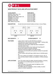
<strong>TV</strong> Signal Strength<br />
<strong>TV</strong> signal strength is measured in decibel Micro<br />
Volts (dBuV) more commonly known as dB.<br />
The ideal signal strength at the television outlet<br />
is 69dBuV. The ideal Signal Range is between<br />
65-72dBuV.<br />
Low signals need to be increased. This can be<br />
achieved by using a larger antenna with more gain<br />
or by the use of an amplifier.<br />
High signals need to be decreased. This can be<br />
achieved by using a drop tap or splitter.<br />
The closer the antenna is to the television<br />
transmitter the higher the signal strength is going<br />
to be.<br />
By using the same antenna and 20m of RG6 Quad<br />
Shield Coax Cable we can classify the Prime,<br />
Fringe and Outer Fringe areas by the level of signal<br />
received at the outlet.<br />
If in a Prime reception area the signal strength will<br />
be greater than 69dBuV at the outlet.<br />
If in a Fringe reception area the signal strength will<br />
be greater than 66dBuV at the outlet.<br />
The prime reception area is a location that<br />
an antenna with minimal gain can be installed<br />
to get the ideal signal range or above at the<br />
television outlet.<br />
An outer fringe reception area is a location that<br />
an antenna with maximum amount of gain must<br />
be installed to provide an ideal signal range at the<br />
outlet. It is also likely that an amplifier may need<br />
to be installed to increase the signal level.<br />
MA<strong>TV</strong> Outlet - 69dBuV Standard Outlet - 240V<br />
62dBuV 65dBuV 72dBuV 75dBuV<br />
69dBuV<br />
Low Signal Acceptable Signal Acceptable Signal<br />
High Signal<br />
If in a Outer Fringe Area the signal will be lower<br />
than 66dBuV.<br />
To compensate for a Fringe Area reception we can<br />
use an antenna with more forward gain to increase<br />
the signal strength at the outlet.<br />
PRIME FRINGE OUTER FRINGE<br />
69dBuV 66dBuV
Signal Quality<br />
Signal quality is more important than<br />
signal strength.<br />
Pixilation or blocking are the result of poor quality<br />
digital television signal. When an antenna is<br />
installed it must be in a location that has a good<br />
quality Digital Television Signal. The difference<br />
between quality television reception and<br />
annoying pixilation/blocking can be a matter<br />
of a few metres. A site survey can be done prior<br />
to antenna installation to make sure that the<br />
location of the antenna is suitable for high quality<br />
digital television reception.<br />
Take a few minutes to walk along the roof with<br />
the antenna and field strength meter to find<br />
the ultimate location to mount the antenna.<br />
PIXILATION QUALITY PICTURE<br />
MA<strong>TV</strong> BASICS<br />
7
MA<strong>TV</strong> BASICS<br />
8<br />
<strong>Clipsal</strong> <strong>TV</strong> <strong>Cabling</strong> <strong>Solutions</strong><br />
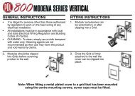
Signal Loss - Cable<br />
Losses are a part of any MA<strong>TV</strong> System. You may<br />
start out with an acceptable signal level at the<br />
antenna but due to losses in the cable or splitter<br />
may not be acceptable when at the outlet.<br />
Signal Strength is lost over a length of cable. The<br />
losses are easy to calculate as losses are consistent<br />
per meter.<br />
Losses are calculated separately for VHF and UHF<br />
frequencies. The golden rule is the higher the<br />
frequency the higher the loss. We need to calculate<br />
losses for both VHF and UHF in every <strong>TV</strong> design to<br />
ensure that we have a balanced system.<br />
VHF = Very High Frequency - losses are low.<br />
(0.053dB per meter RG6 Quad Shield).<br />
UHF = Ultra High Frequency - losses are high<br />
(0.21dB per meter RG6 Quad Shield).<br />
As a general rule of thumb cable runs of up to<br />
50m can be done in RG6. If longer cable runs are<br />
required then you would change the cable size<br />
to RG11 as the losses on RG11 are much lower.<br />
VHF and UHF losses are an average to cover all<br />
frequencies of the VHF and UHF range. This is a<br />
guide only. See pages 46-49 for cable losses for<br />
frequency ranges.<br />
RG6 Cable Losses Frequency 1m 10m 20m 30m 40m 50m<br />
VHF (0-12) 0.053dB 0.53dB 1.06dB 1.59dB 2.12dB 2.65dB<br />
UHF (21-69) 0.21dB 2.1dB 4.2dB 6.3dB 8.4dB 10.4dB<br />
RG11 Cable Losses Frequency 1m 10m 20m 30m 40m 50m<br />
RG6 Quad Shield<br />
Coax Cable<br />
VHF = 70dB<br />
UHF = 70dB<br />
VHF (0-12) 0.032dB 0.32dB 0.64dB 0.96dB 1.28dB 1.6dB<br />
UHF (21-69) 0.131dB 1.31dB 2.62dB 3.93dB 5.24dB 6.55dB<br />
10m 20m 30m 40m 50m<br />
VHF = 69.47dB<br />
UHF = 67.9dB<br />
VHF = 68.94dB<br />
UHF = 65.8dB<br />
VHF = 68.41dB<br />
UHF = 63.7dB<br />
VHF = 67.88dB<br />
UHF = 61.6dB<br />
VHF = 67.35dB<br />
UHF = 59.6dB
Signal Loss - Splitters<br />
All passive splitters have losses. The signal<br />
strength is reduced every time you split the signal.<br />
The more ways the signal is split the higher<br />
the losses.<br />
When installing or adding to an antenna, the<br />
losses for splitters must be taken into account as<br />
well as losses over cable.<br />
20m RG6<br />
Lounge<br />
65.4 dB<br />
LOSSES FOR CLIPSAL TERRESTRIAL SPLITTER RANGE<br />
Frequency 2 Way 3 Way 4 Way 6 Way 8 Way<br />
46-470MHz VHF
ANTENNAS - HIGH PERFORMANCE<br />
10<br />
<strong>Clipsal</strong> <strong>TV</strong> <strong>Cabling</strong> <strong>Solutions</strong><br />
HIGH PERFORMANCE<br />
13 Element Combination 2ANCOM3<br />
VHF UHF<br />
Channels 1-12 28-50<br />
Forward Gain 8dB 12dB<br />
F/B Ratio >12dB >14dB<br />
Connection F-Type<br />
Balun High Perform. PCB<br />
Reflectors Snap out<br />
U bolt Assembled<br />
Reception Area Prime<br />
13 Element Combination 2ANCOM3WB<br />
VHF UHF<br />
Channels 1-12 28-69<br />
Forward Gain 8dB 12dB<br />
F/B Ratio >12dB >14dB<br />
Connection F-Type<br />
Balun High Perf. PCB<br />
Reflectors Snap out<br />
U bolt Assembled<br />
Reception Area Prime
HIGH PERFORMANCE<br />
17 Element Combination 2ANCOM4<br />
VHF UHF<br />
Channels 2-12 28-40<br />
Forward Gain 9dB 12dB<br />
F/B Ratio >12dB >14dB<br />
Connection F-Type<br />
Balun High Perform. PCB<br />
Reflectors Snap out<br />
U bolt Assembled<br />
Reception Area Fringe<br />
28 Element Combination 2ANCOM6<br />
VHF UHF<br />
Channels 2-12 28-40<br />
Forward Gain 10dB 15dB<br />
F/B Ratio >16dB >16dB<br />
Connection F-Type<br />
Balun High Perform. PCB<br />
Reflectors Snap out<br />
U bolt Assembled<br />
Reception Area Outer Fringe<br />
ANTENNAS - HIGH PERFORMANCE<br />
11
ANTENNAS - HIGH PERFORMANCE<br />
12<br />
<strong>Clipsal</strong> <strong>TV</strong> <strong>Cabling</strong> <strong>Solutions</strong><br />
HIGH PERFORMANCE<br />
Newcastle Antenna 2ANCOM2NEW<br />
VHF UHF<br />
Channels 3 & 5A 28-57<br />
Forward Gain 5dB 13dB<br />
F/B Ratio >17dB >20dB<br />
Connection F-Type<br />
Balun High Perform. PCB<br />
Reflectors Snap out<br />
U bolt Assembled<br />
Reception Area Prime/Fringe<br />
Bunbury Antenna 2ANCOM2SW<br />
VHF UHF<br />
Channels 3 & 5A 30-40<br />
Forward Gain 5dB 13dB<br />
F/B Ratio >11.5dB >18dB<br />
Connection F-Type<br />
Balun High Perform. PCB<br />
Reflectors Snap out<br />
U bolt Assembled<br />
Reception Area Prime/ Fringe
HIGH PERFORMANCE<br />
14 Element Combination 2ANCOMD14<br />
VHF UHF<br />
Channels 6-12 28-50<br />
Forward Gain 7.5dB 12dB<br />
F/B Ratio >16dB >16dB<br />
Connection F-Type<br />
Balun High Perform. PCB<br />
Reflectors Snap out<br />
U bolt Assembled<br />
Reception Area Prime/Fringe<br />
14 Element Combination 2ANCOMD14WB<br />
VHF UHF<br />
Channels 6-12 28-69<br />
Forward Gain 7.5dB 12dB<br />
F/B Ratio >16dB >16dB<br />
Connection F-Type<br />
Balun High Perform. PCB<br />
Reflectors Snap out<br />
U bolt Assembled<br />
Reception Area Prime/Fringe<br />
24 Element Combination 2ANCOMD24<br />
VHF UHF<br />
Channels 1-12 28-69<br />
Forward Gain 8dB 15dB<br />
F/B Ratio >16dB >16dB<br />
Connection F-Type<br />
Balun High Perform. PCB<br />
Reflectors Snap out<br />
U bolt Assembled<br />
Reception Area Fringe<br />
ANTENNAS - HIGH PERFORMANCE<br />
13
ANTENNAS - CARAVAN<br />
14<br />
<strong>Clipsal</strong> <strong>TV</strong> <strong>Cabling</strong> <strong>Solutions</strong><br />
CARAVAN ANTENNA<br />
Caravan Antenna 2ANCOMCAR<br />
VHF Horizontal<br />
UHF Vertical<br />
VHF Vertical<br />
UHF Horizontal<br />
VHF UHF<br />
Channels 0-12 28-69<br />
Forward Gain 4dB 8dB<br />
F/B Ratio >10dB >14dB<br />
Connection F-Type<br />
Balun F-Type Ferrite Balun<br />
Reflectors None<br />
U bolt Assembled<br />
Reception Area Prime<br />
VHF Horizontal<br />
UHF Horizontal<br />
VHF Vertical<br />
UHF Horizontal
ECONOMY MODELS<br />
13 Element Combination Economy 2ANCOMA13<br />
VHF UHF<br />
Channels 2-12 28-36<br />
Forward Gain 5dB 7.5dB<br />
F/B Ratio >8dB >20dB<br />
Connection F-Type<br />
Balun Ferrite Balun<br />
Reflectors None<br />
U bolt Assembled<br />
Reception Area Prime<br />
17 Element Combination Economy 2ANCOMA17<br />
VHF UHF<br />
Channels 2-12 28-36<br />
Forward Gain 6dB 10dB<br />
F/B Ratio >10dB >20dB<br />
Connection F-Type<br />
Balun Ferrite Balun<br />
Reflectors Snap Out<br />
U bolt Assembled<br />
Reception Area Prime/Fringe<br />
32 Element Combination Economy 2ANVULP2<br />
VHF UHF<br />
Channels 6-12 28-69<br />
Forward Gain 8dB 11dB<br />
F/B Ratio >20dB >20dB<br />
Connection F-Type<br />
Balun None<br />
Reflectors None<br />
U bolt Assembled<br />
Reception Area Prime/Fringe<br />
ANTENNAS - ECONOMY MODELS<br />
15
ANTENNAS - CROSS POLARITY<br />
16<br />
<strong>Clipsal</strong> <strong>TV</strong> <strong>Cabling</strong> <strong>Solutions</strong><br />
HIGH PERFORMANCE CROSS POLARITY<br />
13 Element Cross Polarity Combination 2ANUV13WB<br />
VHF UHF<br />
Channels 6-12 50-69<br />
Forward Gain 7dB 12dB<br />
F/B Ratio >12dB >14dB<br />
Connection F-Type<br />
Balun High Perform. PCB<br />
Reflectors Snap Out<br />
U bolt Assembled<br />
Reception Area Prime/Fringe<br />
14 Element Cross Polarity Combination 2ANUV14<br />
VHF UHF<br />
Channels 6-12 28-50<br />
Forward Gain 7dB 11dB<br />
F/B Ratio >12dB >16dB<br />
Connection F-Type<br />
Balun High Perform. PCB<br />
Reflectors Snap Out<br />
U bolt Assembled<br />
Reception Area Prime/Fringe<br />
All vertically mounted antennas<br />
will require a 2ANVB15 bracket.<br />
Refer to page 31.
HIGH PERFORMANCE CROSS POLARITY<br />
16 Element Cross Polarity Combination 2ANUV16<br />
VHF UHF<br />
Channels 2-12 28-50<br />
Forward Gain 7dB 12dB<br />
F/B Ratio >12dB >14dB<br />
Connection F-Type<br />
Balun High Perform. PCB<br />
Reflectors Snap Out<br />
U bolt Assembled<br />
Reception Area Prime/Fringe<br />
19 Element Cross Polarity Combination 2ANUV19<br />
VHF UHF<br />
Channels 1-12 28-69<br />
Forward Gain 7dB 12dB<br />
F/B Ratio >12dB >16dB<br />
Connection F-Type<br />
Balun High Perform. PCB<br />
Reflectors Snap Out<br />
U bolt Assembled<br />
Reception Area Prime/Fringe<br />
ANTENNAS - CROSS POLARITY<br />
17
ANTENNAS - UHF YAGI<br />
18 <strong>Clipsal</strong> <strong>TV</strong> <strong>Cabling</strong> <strong>Solutions</strong><br />
UHF YAGI<br />
12 Element Yagi 2ANUY12WB<br />
UHF<br />
Channels 28-69<br />
Forward Gain 12.5dB<br />
F/B Ratio >14dB<br />
Connection F-Type<br />
Balun High Perform. PCB<br />
Reflectors Snap Out<br />
U bolt Elevat. Tilt Bracket<br />
Reception Area Prime/Fringe<br />
20 Element Yagi 2ANUY20WB<br />
Tilt bracket supplied<br />
for UHF Antennas<br />
UHF<br />
Channels 28-69<br />
Forward Gain 14.5dB<br />
F/B Ratio >20dB<br />
Connection F-Type<br />
Balun High Perform. PCB<br />
Reflectors Snap Out<br />
U bolt Elevat. Tilt Bracket<br />
Reception Area Fringe/Outer Fringe
UHF YAGI<br />
10 Element Yagi Band 4 2ANUY10/4<br />
UHF<br />
Channels 28-35<br />
Forward Gain 12.5dB<br />
F/B Ratio >16dB<br />
Connection F-Type<br />
Balun High Perform. PCB<br />
Reflectors Snap Out<br />
U bolt Elevat. Tilt Bracket<br />
Reception Area Prime<br />
18 Element Yagi Band 4 2ANUY18/4<br />
UHF<br />
Channels 28-35<br />
Forward Gain 13.5dB<br />
F/B Ratio >20dB<br />
Connection F-Type<br />
Balun High Perform. PCB<br />
Reflectors Snap Out<br />
U bolt Elevat. Tilt Bracket<br />
Reception Area Fringe<br />
18 Element Yagi Band 5 2ANUY18/5<br />
UHF<br />
Channels 35-69<br />
Forward Gain 14dB<br />
F/B Ratio >20dB<br />
Connection F-Type<br />
Balun High Perform. PCB<br />
Reflectors Snap Out<br />
U bolt Elevat. Tilt Bracket<br />
Reception Area Fringe/Outer Fringe<br />
ANTENNAS - UHF YAGI<br />
19
ANTENNAS - UHF PHASED ARRAY<br />
20<br />
<strong>Clipsal</strong> <strong>TV</strong> <strong>Cabling</strong> <strong>Solutions</strong><br />
UHF PHASED ARRAY<br />
8 Element Phased Array 2ANUPA1<br />
UHF<br />
Channels 21-69<br />
Forward Gain 8-11dB<br />
F/B Ratio >15dB<br />
Connection F-Type<br />
Balun None<br />
Reflectors Rear X Type<br />
U bolt Assembled<br />
Reception Area Prime<br />
16 Element Phased Array 2ANUPA2<br />
UHF<br />
Channels 21-69<br />
Forward Gain 13.5dB<br />
F/B Ratio >20dB<br />
Connection F-Type<br />
Balun None<br />
Reflectors Rear X Type<br />
U bolt Assembled<br />
Reception Area Outer Fringe
UHF X TYPE<br />
23 Element X Style 2ANUX23<br />
UHF<br />
Channels 21-69<br />
Forward Gain 10dB<br />
F/B Ratio >17dB<br />
Connection F-Type<br />
Balun High Perform. PCB<br />
Reflectors Bolt on<br />
U bolt Elevat. Tilt Bracket<br />
Reception Area Prime<br />
43 Element X Style 2ANUX43<br />
UHF<br />
Channels 21-69<br />
Forward Gain 13dB<br />
F/B Ratio >20dB<br />
Connection F-Type<br />
Balun High Perform. PCB<br />
Reflectors Bolt On<br />
U bolt Elevat. Tilt Bracket<br />
Reception Area Fringe<br />
91 Element X Style 2ANUX91<br />
UHF<br />
Channels 21-69<br />
Forward Gain 15dB<br />
F/B Ratio >20dB<br />
Connection F-Type<br />
Balun High Perform. PCB<br />
Reflectors Bolt On<br />
U bolt Elevat. Tilt Bracket<br />
Reception Area Outer Fringe<br />
ANTENNAS - UHF X TYPE<br />
21
ANTENNAS ANTENNAS ANTENNAS - - VHF VHF YAGI<br />
22<br />
VHF YAGI<br />
<strong>Clipsal</strong> <strong>TV</strong> <strong>Cabling</strong> <strong>Solutions</strong><br />
7 Element Yagi 2ANVY7<br />
10 Element Yagi 2ANVY10<br />
VHF<br />
Channels 6-12<br />
Forward Gain 8.8dB<br />
F/B Ratio >16dB<br />
Connection F-Type<br />
Balun High Perform. PCB<br />
Reflectors Snap Out<br />
U bolt Assembled<br />
Reception Area Prime<br />
VHF<br />
Channels 6-12<br />
Forward Gain 11-12dB<br />
F/B Ratio >16dB<br />
Connection F-Type<br />
Balun High Perform. PCB<br />
Reflectors Snap Out<br />
U bolt Assembled<br />
Reception Area Fringe<br />
18 Element Yagi 2ANVY18<br />
VHF<br />
Channels 6-12<br />
Forward Gain 14dB<br />
F/B Ratio >20dB<br />
Connection F-Type<br />
Balun High Perform. PCB<br />
Reflectors Snap Out<br />
U bolt Assembled<br />
Reception Area Prime
VHF LOG PERIODIC<br />
8 Element Log Periodic 2ANV2WB<br />
VHF<br />
Channels 0-12<br />
Forward Gain 4-8dB<br />
F/B Ratio >12dB<br />
Connection F-Type<br />
Balun High Perform. PCB<br />
Reflectors None<br />
U bolt Assembled<br />
Reception Area Prime<br />
9 Element Log Periodic 2ANV3WB<br />
VHF<br />
Channels 0-12<br />
Forward Gain 5-11dB<br />
F/B Ratio >15dB<br />
Connection F-Type<br />
Balun High Perform. PCB<br />
Reflectors None<br />
U bolt Assembled<br />
Reception Area Fringe<br />
12 Element Log Periodic 2ANV4WB<br />
VHF<br />
Channels 0-12<br />
Forward Gain 6-12dB<br />
F/B Ratio >15dB<br />
Connection F-Type<br />
Balun High Perform. PCB<br />
Reflectors None<br />
U bolt Assembled<br />
Reception Area Outer Fringe<br />
ANTENNAS ANTENNAS - VHF LOG PERIODIC<br />
- VHF UHF<br />
23
ANTENNAS - VHF PHASED ARRAY<br />
24<br />
<strong>Clipsal</strong> <strong>TV</strong> <strong>Cabling</strong> <strong>Solutions</strong><br />
VHF PHASED ARRAY<br />
8 Element Phased Array 2ANVPA1<br />
VHF<br />
Channels 6-12<br />
Forward Gain 7-9.5dB<br />
F/B Ratio >16dB<br />
Connection F-Type<br />
Balun None<br />
Reflectors None<br />
U bolt Assembled<br />
Reception Area Prime/Fringe<br />
16 Element Phased Array 2ANVPA2<br />
VHF<br />
Channels 6-12<br />
Forward Gain 12dB<br />
F/B Ratio >16dB<br />
Connection F-Type<br />
Balun None<br />
Reflectors None<br />
U bolt Assembled<br />
Reception Area Fringe/Outer Fringe
FM<br />
3 Element FM 2ANFM3<br />
VHF<br />
Channels 88-108Mhz<br />
Forward Gain 5dB<br />
F/B Ratio >15dB<br />
Connection F-Type<br />
Balun High Perform. PCB<br />
Reflectors None<br />
U bolt Assembled<br />
Reception Area Prime<br />
8 Element FM 2ANFM8<br />
VHF<br />
Channels 88-108Mhz<br />
Forward Gain 10dB<br />
F/B Ratio >17dB<br />
Connection F-Type<br />
Balun High Perform. PCB<br />
Reflectors None<br />
U bolt Assembled<br />
Reception Area Fringe/Outer Fringe<br />
ANTENNAS - FM<br />
25
MOUNTING ACCESSORIES<br />
26<br />
<strong>Clipsal</strong> <strong>TV</strong> <strong>Cabling</strong> <strong>Solutions</strong><br />
Curved Fascia Brackets<br />
1.2m used for smaller antennas - 2ANCFB12<br />
1.5m used for small to medium antennas - 2ANCFB15<br />
1.8m used for small to medium antennas - 2ANCFB18<br />
1.5m used for larger antennas - 2ANCFBHD<br />
• Mounted to the fascia or wall<br />
• Generally used when height of the antenna is not a issue<br />
• Used for small to medium sized antennas<br />
• Stay bars can be used to support the antenna if required.<br />
Curved Fascia Brackets
Stay Bars<br />
Stay Bar<br />
Stay bar set of 2 x 1200mm (4 foot) - 2ANSB4<br />
Stay bar set of 2 x 1800mm (6 foot) - 2ANSB6<br />
Stay bar set of 2 x 2400mm (8 foot) - 2ANSB8<br />
Stay bar collar - 2ANSBC<br />
All stay bars require a stay bar collar for mounting.<br />
One end of the stay bar is fixed to the stay bar collar.<br />
The other end of the stay bar is fixed to the roof.<br />
(Drill through tile to screw to baton for tiled roof)<br />
Used to support • Antenna mounts<br />
• Curved fascia brackets<br />
• Tripod roof mounts<br />
• Rafter mounts<br />
• Masts.<br />
Stay Bar Collar<br />
MOUNTING ACCESSORIES<br />
27
MOUNTING ACCESSORIES<br />
28<br />
<strong>Clipsal</strong> <strong>TV</strong> <strong>Cabling</strong> <strong>Solutions</strong><br />
Tripod Roof Mounts<br />
Tripod Roof Mount - TILE - 2ANTRPT<br />
The easiest way to mount an antenna<br />
2ANTRPT<br />
• Drill through tile to baton for fixing with appropriate anchors<br />
• Bend the supports to adjust for any roof angle<br />
2ANTRPM<br />
• Use existing roof screws to fix mount in place<br />
• Bend the supports to adjust for any roof angle<br />
Tripod Roof Mount - METAL - 2ANTRPM
Rafter Mounts<br />
Lead Flashing Kit<br />
Rafter Mount - 2ANRM25 - 2ANRM32<br />
Roof Seal - Metal - 2ANPFK<br />
Rafter Mount<br />
Rafter Mount 1.8m x 25mm - 2ANRM25<br />
Rafter Mount 1.8m x 32mm - 2ANRM32<br />
Lead Flashing Kit (tiled roofs) - 2ANLFK<br />
Pipe Rubber Roof Seal (metal Roofs) - 2ANPFK<br />
Smaller antennas use the 2ANRM25<br />
Medium to larger antennas use the 2ANRM32<br />
Tiled roof must use a 2ANLFK<br />
Metal roof use the 2ANPFK<br />
Lead Flashing Kit - 2ANLFK<br />
Pipe Rubber Roof Seal<br />
MOUNTING ACCESSORIES<br />
29
MOUNTING ACCESSORIES<br />
30<br />
<strong>Clipsal</strong> <strong>TV</strong> <strong>Cabling</strong> <strong>Solutions</strong><br />
Wall Mounts/Masts<br />
Wall Mount<br />
Wall Mount 230mm (9inch) - 2ANWB09<br />
Wall Mount 280mm (11inch) - 2ANWB11<br />
Wall Mount 690mm (27inch) - 2ANWB27<br />
Wall Mount 1020mm (40inch) - 2ANWB40<br />
Wall Mount 1400mm (55inch) - 2ANWB55<br />
Wall Mount kit (2ANWB9 + 2ANWB27) - 2ANWB17K<br />
Mast 3.0m x 32mm - 2ANGM3032<br />
Mast 4.5m x 32mm - 2ANGM4532<br />
Mast 4.5m x 38mm - 2ANGM4538<br />
V Block offset (used to mount horizontal and vertical poles together) 2ANVBO<br />
Bolt for V Block - 2ANVB<br />
Mast<br />
Used to gain extra height required for better <strong>TV</strong> reception<br />
Mast extensions available for extra height if required.<br />
V Block<br />
offset
Vertical Stand Off Bracket<br />
Vertical<br />
Stand off Bracket<br />
Vertical Stand off Bracket 375mm (15 inch) - 2ANVB15<br />
Used to mount an antenna vertically<br />
All antennas mounted vertically need a stand off bracket<br />
If a stand off bracket is not used signal problems may be encountered.<br />
All vertically mounted antennas<br />
will require a 2ANVB15 bracket.<br />
MOUNTING ACCESSORIES<br />
31
MOUNTING ACCESSORIES<br />
32<br />
<strong>Clipsal</strong> <strong>TV</strong> <strong>Cabling</strong> <strong>Solutions</strong><br />
Guy Wire Fixing<br />
2ANIRM<br />
Iron Roof Mount<br />
Mast<br />
Guy ring plate<br />
2ANGC C<br />
Guy Wire Bracket/Cleat ket/Cleat<br />
Guy Wire<br />
Lock ring<br />
collar<br />
Turnbuckle<br />
2ANGWC<br />
Guy Wire<br />
Clamp/Grip<br />
2ANTBS<br />
Thimble
Guy Wire Fixing<br />
Guy Wire 180m reel -2ANGWR<br />
Guy Wire Spool (Coiled) - 2ANGW<br />
Guy ring plate x 32mm (suites 32mm mast) - 2ANGR32<br />
Guy ring plate x 38mm (suites 38mm mast) - 2ANGR38<br />
Lock ring collar x 32mm (suites 32mm mast) - 2ANLR32<br />
Lock ring collar x 38mm (suites 38mm mast) - 2ANLR38<br />
Guy Wire Cleat - 2ANGC<br />
Guy Wire Clamp - 2ANGWC<br />
Turnbuckle x 6mm (1/4 inch) - 2ANTBK6<br />
Turnbuckle x 8mm (5/16 inch) - 2ANTBK8<br />
Thimble - 2ANTBS<br />
Mast Extension<br />
Mount fixing points on roof 3m from base of mast<br />
Mount guy ring 3m above the base of the mast for 4.5m masts<br />
Mount guy ring 2.5m above the base of the mast for 3m masts<br />
Use thimbles to stop the guy wire rubbing against the mount<br />
Use turnbuckles to tighten the guy wire.<br />
MOUNTING ACCESSORIES<br />
33
MOUNTING ACCESSORIES<br />
34<br />
<strong>Clipsal</strong> <strong>TV</strong> <strong>Cabling</strong> <strong>Solutions</strong><br />
Mast Extensions<br />
Mast Extension - 2ANME<br />
Mast Extension Kit - 2ANMEK<br />
Mast 3.0m x 32mm - 2ANGM3032<br />
Mast 4.5m x 32mm - 2ANGM4532<br />
Mast 4.5m x 38mm - 2ANGM4538<br />
V Block offset (used to mount horizontal and vertical poles together) - 2ANVBO<br />
Wall Mounts/Masts<br />
Used to get extra height required for better <strong>TV</strong> reception<br />
May require some form of support • Guy wire support<br />
• Stay bar support<br />
Mast<br />
V Block offset
Mast Extension Kit<br />
Mast Extension Kit - 2ANMEK<br />
Mast Extension<br />
Mast Extension- 2ANME<br />
V Block clamps two poles together such as a mast to a wall/eave bracket.<br />
MOUNTING ACCESSORIES<br />
35
MOUNTING ACCESSORIES<br />
36<br />
<strong>Clipsal</strong> <strong>TV</strong> <strong>Cabling</strong> <strong>Solutions</strong><br />
Flat Wall Mount<br />
Metal Fascia<br />
Wall Bracket<br />
Flat Wall Mount Bracket - 2ANFWM<br />
Metal Fascia - 2ANMFB<br />
Mast
V Block<br />
V Block - 2ANVB<br />
U Bolt 5 inches - 2ANUBM<br />
U Bolt 7 inches - 2ANUBL<br />
V Offset Block<br />
V Offset Block - 2ANVBO<br />
U Bolt 5 inches - 2ANUBM<br />
U Bolt 7 inches - 2ANUBL<br />
2ANVB<br />
Block<br />
2ANUBM or 2ANUBL<br />
U Mount<br />
V Block clamps at 90 degrees to the mast. This is ideal for horizontal mounting of antennas.<br />
MOUNTING ACCESSORIES<br />
37
SPLITTERS 38<br />
<strong>Clipsal</strong> <strong>TV</strong> <strong>Cabling</strong> <strong>Solutions</strong><br />
2 Way Terrestrial Splitter 5-1000MHz 3105SPF2<br />
Not suitable for Satellite Television Transmission<br />
Losses VHF 46-470MHz
6 Way Terrestrial Splitter 5-1000MHz 3105SPF6<br />
Power Pass<br />
Losses VHF 46-470MHz
SPLITTERS 40<br />
4.2dB<br />
20m Cable Loss<br />
<strong>Clipsal</strong> <strong>TV</strong> <strong>Cabling</strong> <strong>Solutions</strong><br />
Powered Splitter 37-860MHz 3105VDU24T<br />
Frequency Range<br />
37-860Mhz<br />
All Free to Air Channels<br />
Output Ports 4<br />
Input Ports<br />
1x Antenna Input<br />
1x Modulated Input<br />
Power Supply 12VDC<br />
3 Power Options<br />
·Local<br />
·Remote via Modulator<br />
·Remote via Power Injector<br />
Antenna Input only<br />
Variable Gain Control<br />
+3dB Gain<br />
-15dB Attenuation<br />
IR Pass Back No<br />
IR Expansion Port No<br />
Powered Splitter 37-860MHz 3105VDU38IRT<br />
67.8dBuV<br />
72dB<br />
70dB<br />
Gain Control + 2dB<br />
Frequency Range<br />
37-860Mhz<br />
All Free to Air Channels<br />
Output Ports 8<br />
Input Ports<br />
1x Antenna Input<br />
2x Modulated Inputs<br />
Power Supply 12VDC<br />
3 Power Options<br />
·Local<br />
·Remote via Modulator<br />
·Remote via Power Injector<br />
Antenna Input only<br />
Variable Gain Control<br />
+3dB Gain<br />
-15dB Attenuation<br />
IR Pass Back Yes<br />
IR Expansion Port Yes
4.2dB<br />
20m Cable Loss<br />
6 Way Powered Splitter 37-860MHz 8072/6VHP<br />
Frequency Range<br />
37-860Mhz<br />
All Free to Air Channels<br />
Output Ports 6<br />
Input Ports<br />
1x Antenna Input<br />
1x Modulated Input<br />
Power Supply 12VDC<br />
3 Power Options<br />
·Local<br />
·Remote via Modulator<br />
·Remote via Power Injector<br />
Antenna Input only<br />
Variable Gain Control<br />
+3dB Gain<br />
-15dB Attenuation<br />
IR Pass Back No<br />
IR Expansion Port No<br />
8 Way Powered Splitter 37-860MHz 8073/8VHPIR<br />
67.8dBuV<br />
72dB<br />
70dB<br />
Gain Control + 2dB<br />
Frequency Range<br />
37-860Mhz<br />
All Free to Air Channels<br />
Output Ports 8<br />
Input Ports<br />
1x Antenna Input<br />
2x Modulated Inputs<br />
Power Supply 12VDC<br />
3 Power Options<br />
·Local<br />
·Remote via Modulator<br />
·Remote via Power Injector<br />
Antenna Input only<br />
Variable Gain Control<br />
+3dB Gain<br />
-15dB Attenuation<br />
IR Pass Back Yes<br />
IR Expansion Port Yes<br />
SPLITTERS<br />
41
SPLITTERS 42<br />
<strong>Clipsal</strong> <strong>TV</strong> <strong>Cabling</strong> <strong>Solutions</strong><br />
2 Way Satellite Splitter 5-2400MHz 3105SPFP2<br />
Losses 40-1000MHz
Indoor Diplexer 3105DPUV<br />
Outdoor Diplexer 3105DPOUV<br />
Diplexers combine <strong>TV</strong> signals from 2 antennas through 1 coax cable.<br />
DIPLEXERS<br />
43
DROP TAPS<br />
44<br />
<strong>Clipsal</strong> <strong>TV</strong> <strong>Cabling</strong> <strong>Solutions</strong><br />
1 Way Drop Tap 5-2400MHz 3105T1/XX<br />
3105T1/10 3105T1/12 3105T1/15 3105T1/20<br />
Tap Loss 10dB 12dB 15dB 20dB<br />
Through Loss 5-950MHz
75 Ohm Terminator 3105FTER<br />
All unused ports of a Drop Tap or Splitter should<br />
be terminated with a 75 Ohm Terminator to stop<br />
electrical reflections interfering with <strong>TV</strong>s connected<br />
to the system.<br />
Pack of 10.<br />
DROP TAPS<br />
45
COAXIAL CABLE - RG6<br />
46<br />
RG6<br />
<strong>Clipsal</strong> <strong>TV</strong> <strong>Cabling</strong> <strong>Solutions</strong><br />
RG6 Coaxial Tri Shield Cable<br />
<strong>Catalogue</strong><br />
Number<br />
Conductor Size<br />
(mm)<br />
PVC Jacket<br />
Foil Tape<br />
Aluminium Braid<br />
Description Pack Size<br />
AWG Cond. Type Shield Type<br />
Nom. O.D<br />
(mm)<br />
Foxtel<br />
Approval No.<br />
Insl. & Core<br />
O.D (mm)<br />
60% Aluminium<br />
1.02 +_ 0.03 18 Solid<br />
7.06 +_ 0.02 4.78 +_ 0.13<br />
Braids<br />
Austar<br />
Approval No.<br />
3105RG6T3B RG6 Coax Tri Shield Box 305m Box F10176 N/A<br />
3105RG6T3B<br />
5MHz 55MHz 211MHz 250MHz 270MHz 300MHz 330MHz 350MHz 400MHz 450MHz 500MHz 550MHz 600MHz 750MHz 870MHz 1000MHz 1450MHz 1750MHz 2050MHz<br />
1.90 5.25 10.00 10.82 11.04 11.64 12.26 12.63 13.61 14.43 15.29 16.08 16.73 18.54 20.04 21.49 26.25 28.67 31.04<br />
Attenuation @ 20˚C (dB/100m)<br />
AWG Conductor<br />
Gas injected Foam
RG6 Coaxial Quad Shield Cable<br />
<strong>Catalogue</strong><br />
Number<br />
Conductor Size<br />
(mm)<br />
Description Pack Size<br />
AWG Cond. Type Shield Type<br />
Nom. O.D<br />
(mm)<br />
Foxtel<br />
Approval No.<br />
Insl. & Core<br />
O.D (mm)<br />
60% & 40%<br />
Solid<br />
1.02 +_ 0.03 18<br />
Aluminium 7.54 +_ 0.02 4.78 +_ 0.13<br />
BCCS<br />
Braids<br />
Austar<br />
Approval No.<br />
3105RG6Q3R RG6 Coax Quad Shield 305m Reel F10129 P07982<br />
3105RG6Q3B RG6 Coax Quad Shield 305m Box F10129 P07982<br />
3105RG6Q1R RG6 Coax Quad Shield Box 100m Reel F10129 P07982<br />
3105RG6Q3RF RG6 Coax Quad Shield Flooded 305m Reel F30059 P07985<br />
3105RG6QS15R RG6 Coax Quad Shield Siamese 152.5m Reel F30432 P07984<br />
RG6<br />
5MHz 55MHz 211MHz 250MHz 270MHz 300MHz 330MHz 350MHz 400MHz 450MHz 500MHz 550MHz 600MHz 750MHz 870MHz 1000MHz 1450MHz 1750MHz 2050MHz<br />
1.90 5.25 10.00 10.82 11.04 11.64 12.26 12.63 13.61 14.43 15.29 16.08 16.73 18.54 20.04 21.49 26.25 28.67 31.04<br />
Attenuation @ 20˚C (dB/100m)<br />
3105RG6Qxxx<br />
Siamese Quad Shield<br />
COAXIAL CABLE<br />
47
COAXIAL CABLE - RG11<br />
RG11<br />
48 <strong>Clipsal</strong> <strong>TV</strong> <strong>Cabling</strong> <strong>Solutions</strong><br />
RG11 Coaxial Quad Shield Cable 3105RG11Q3R, 3105RG11Q3RF<br />
<strong>Catalogue</strong><br />
Number<br />
Conductor Size<br />
(mm)<br />
Description Pack Size<br />
AWG Cond. Type Shield Type<br />
Reel Length<br />
(m)<br />
Foxtel<br />
Approval No.<br />
Nom. O.D<br />
(mm)<br />
Austar<br />
Approval No.<br />
3105RG11Q3R RG11 Coax Quad Shield Reel 305m Reel F10175 A02629<br />
3105RG11Q3RF RG11 Coax Quad Shield Flooded Reel 305m Reel F30060 P07986<br />
Insl. & Core<br />
O.D (mm)<br />
60% & 40%<br />
1.63 +_ 0.03 14 Solid BCCS<br />
305 10.34 +_ 0.25 7.32 +_<br />
0.15<br />
Aluminium Braids<br />
5MHz 55MHz 211MHz 250MHz 270MHz 300MHz 330MHz 350MHz 400MHz 450MHz 500MHz 550MHz 600MHz 750MHz 870MHz 1000MHz 1300MHz 1550MHz 1770MHz 2150MHz<br />
1.25 3.15 6.23 6.72 7.00 7.38 7.71 7.94 8.53 9.02 9.51 9.97 10.43 11.97 13.31 14.27 16.00 17.42 19.58 21.61<br />
Attenuation @ 20˚C (dB/100m)
RG59 Coaxial Dual Shield Cable<br />
<strong>Catalogue</strong><br />
Number<br />
Conductor Size<br />
Nom. O.D Insl. & Core O.D<br />
AWG Cond. Type Shield Type<br />
(mm) +_ (mm) +_ (mm) +_<br />
0.81 1 20 Solid BCCS<br />
Description Pack Size<br />
60% Aluminium<br />
Braids<br />
6.10 0.2 3.86 0.13<br />
RG59<br />
3105RG59D1R, 3105RG59D3B<br />
Foxtel<br />
Approval No.<br />
Austar<br />
Approval No.<br />
3105RG59D1R RG59 Coax Dual Shield 100m Reel N/A N/A<br />
3105RG59D3B RG59 Coax Dual Shield Box 305m Box N/A N/A<br />
5MHz 55MHz 211MHz 250MHz 270MHz 300MHz 330MHz 350MHz 400MHz 450MHz 500MHz 550MHz 600MHz 750MHz 870MHz 1000MHz<br />
2.82 6.73 12.47 13.45 13.85 14.6 15.29 15.75 16.73 17.72 18.70 19.52 20.34 22.87 24.85 26.64<br />
Attenuation @ 20˚C (dB/100m)<br />
COAXIAL CABLE RG59<br />
49
COAXIAL CABLE CONNECTORS<br />
50<br />
<strong>Clipsal</strong> <strong>TV</strong> <strong>Cabling</strong> <strong>Solutions</strong><br />
RG6 COMPRESSION<br />
RG6 Compression Tool 3105CT611C<br />
Easy to use<br />
Swivel Head for RG6 and RG11<br />
For use with the following connectors:<br />
3105RG6FC50 - RG6 (Packet of 50)<br />
3105RG11FC2 - RG11 (Packet of 2)<br />
RG6 Compression Connector 3105RG6FC50<br />
RG6 & RG59 Cable Stripper<br />
3105RG6FC50 (Packet of 50)<br />
Approval Number<br />
Foxtel F30029<br />
Austar A06948<br />
Select <strong>TV</strong> Not Required<br />
Easy to use - Termination techniques on pages 54-55<br />
Suits RG6 and RG59 cables<br />
3105CS6
RG11 COMPRESSION<br />
RG11 Compression Tool 3105CT611C<br />
Easy tto<br />
use<br />
Swivel Swive Head for RG6 and RG11<br />
For use us with the following connectors:<br />
3105RG6FC50 3105R - RG6<br />
3105RG11FC2 - RG11<br />
RG11 Compression Connector 3105RG11FC2<br />
3105RG11FC2 3105 (Packet of 2)<br />
Approval Number<br />
Foxtel Fox<br />
F30360<br />
Austar Aus<br />
A06949<br />
Select Sele <strong>TV</strong> Not Required<br />
RG11 Cable Stripper<br />
3105CS11<br />
Easy to use<br />
Suits RG11 Coax Cables<br />
COAXIAL CABLE CONNECTORS<br />
51
COAXIAL CABLE CONNECTORS<br />
52 <strong>Clipsal</strong> <strong>TV</strong> <strong>Cabling</strong> <strong>Solutions</strong><br />
RG6 RADIAL CRIMP<br />
RG6 Radial Crimp Tool 3105CT611<br />
RG6 Crimp Connector 3105RG6F<br />
RG6 Cable Stripper<br />
Easy to use<br />
For use with the following connectors:<br />
3105RG59F, 3105BNC6, 3105BNC59<br />
3105RG6F, 3105RG6PM, 3105RG6PF<br />
3105RG6F (Packet of 10)<br />
For use with Radial Crimp Tool<br />
Easy to use<br />
Suits RG6 and RG59 Cables<br />
Approval Number<br />
Foxtel F10179/C<br />
Austar A01509<br />
Select <strong>TV</strong> Not Required<br />
3105CS6
RG59 RADIAL CRIMP<br />
RG59 Radial Crimp Tool 3105CT611<br />
RG59 Compression Connector 3105RG59F<br />
RG59 Cable Stripper<br />
Easy to use<br />
For use with the following connectors:<br />
3105RG59F, 3105BNC6, 3105BNC59<br />
3105RG6F, 3105RG6PM, 3105RG6PF<br />
3105RG59F<br />
Packet of 10<br />
For use with radial Crimp Tool<br />
Easy to use<br />
Suits RG6 and RG59 Cables<br />
3105CS6<br />
COAXIAL CABLE CONNECTORS<br />
53
INSTALLATION TIPS<br />
54<br />
<strong>Clipsal</strong> <strong>TV</strong> <strong>Cabling</strong> <strong>Solutions</strong><br />
Do’s and Don’ts<br />
Insert coax cable into the stripping tool with<br />
the end of the coax level with the lip on the<br />
right hand side. Hold the cable close to the<br />
tool and spin around a few times. Not enough<br />
spins of the stripping tool will leave the coax<br />
jacket on and too many spins will cut away<br />
the shielding. Hold the stripping tool by<br />
the jaws and pull away from cable without<br />
opening the jaws of the stripping tool.<br />
The stripped cable will look like the following<br />
diagram.<br />
Fold back the first braid then fold back the<br />
first foil. Fold back the second braid but DO<br />
NOT remove the last foil as this is bonded to<br />
the Dielectric. Fold back braid and foil evenly<br />
in each direction to ensure the connector<br />
slides on easily. A good preparation should<br />
look like the following diagram.
Do’s and Don’ts<br />
Slide the connector on straight. DO NOT slide<br />
connector at an angle because it will damage<br />
the cable. Look at the front of the connector. If<br />
A connector slid on at an angle will result in the cable bl looking l king like the following follow diagram.<br />
Slide the cable up to the base of the<br />
connector. A good termination should be level<br />
with the base of the connector.<br />
the cable is damaged then remove<br />
the connector and start again.<br />
DO NOT terminate connector.<br />
When the cable is inside the connector<br />
it will look like the following diagram.<br />
Once the the connector has been installed correctly only<br />
then should you use the tool to terminate.<br />
INSTALLATION TIPS<br />
55
INSTALLATION TOOLS<br />
56<br />
<strong>Clipsal</strong> <strong>TV</strong> <strong>Cabling</strong> <strong>Solutions</strong><br />
Digital Terrestrial Meter 2ANDTM<br />
Features and Benefits<br />
Displays RF level and post BER together with S/N on large display in real time. Run time in excess of five<br />
hours on a full charge. Built-in charger with rechargeable NiMH battery.<br />
Specifications<br />
VHF 6-12 UHF 21-69<br />
VHF Band 3 and UHF e.g. 167-862 MHz 7 M Bandwidth<br />
Automatic Constellation and transmitter offset<br />
C/N up to 32dB in 0.5dB steps accuracy +-1dB<br />
RF level 25dBuV to 75dBuV accuracy +-1dB over all bandwidth and under indication<br />
Input range -72dBm-20dBm<br />
Charger 100-240V Ac or 12V Dc<br />
Battery 2.4 Ah NiMH 7.2V 6 cell<br />
BCN - PAL + BCN F-Type adaptors included<br />
2x 10dB attenuators included<br />
This meter is a Digital Field Strength Meter and will not measure any channel below VHF 6.
Digital Field Strength Meter<br />
RF Screen<br />
Allows you to scroll oll through VHF and UHF channels and measure the signal strength. strength<br />
Step Through<br />
Use the arrow buttons to scroll through VHF and UHF channels.<br />
RF Level<br />
Shows the level of signal strength numerically.<br />
IIIIIIIIIIIIIII<br />
Bar reading of signal strength.<br />
DVB-T<br />
This will appear if the signal is a digital video broadcast terrestrial. If this appears then press the ON<br />
button to change to the BER page. If this does not appear the signal is an analogue signal.<br />
BER Screen<br />
Measures the Bit Error Ratio.<br />
Step Through<br />
Use the arrow buttons to scroll through the VHF and UHF channels.<br />
BER<br />
Shows the number of errors within the signal. Use to measure the quality of the digital signal only.<br />
PASS<br />
PASS or FAIL will appear dependant on the number of errors.<br />
IIIIIIIIIIIIIII<br />
Bar reading of signal strength.<br />
Step Through V 6<br />
RF Level 72dBuV<br />
IIIIIIIIIIIIIIIIIIIII------------------------<br />
DVB-T<br />
Step Through V 6<br />
BER 0.00E7 **** PASS<br />
IIIIIIIIIIIIIIIIIIIII------------------------<br />
SN 29dB<br />
SN 29dB<br />
Signal to Noise Ratio. Measures the amount of signal versus electrical noise within the cable.<br />
The higher the number the better.<br />
INSTALLATION TOOLS<br />
57
INSTALLATION TOOLS<br />
58<br />
<strong>Clipsal</strong> <strong>TV</strong> <strong>Cabling</strong> <strong>Solutions</strong><br />
MA<strong>TV</strong> Tool Box 3105TOOLBOX<br />
<strong>Clipsal</strong> Australia have provided a MA<strong>TV</strong> tool box that has the essentials required to carry out MA<strong>TV</strong><br />
installations. Refer to chart below for the great range of products included.<br />
Product Cat No. Qty.<br />
Compression Tool 3105CT611C 1<br />
Hex Crimp Tool 3105CT611C 1<br />
Coax Cable Stripper 3105CS6 1<br />
Hex Nut Spanner - 1<br />
Coax Cable Cutters - 1<br />
UTP Cable Stripper - 1<br />
2 Way Splitter Terrestrial 3105SPF2 4<br />
3 Way Splitter Terrestrial 3105SPF3 4<br />
4 Way Splitter Terrestrial 3105SPF4 4<br />
2 Way Splitter Satellite 3105SPFP2 4<br />
3 Way Splitter Satellite 3105SPFP3 4<br />
4 Way Splitter Satellite 3105SPFP4 4<br />
F-Type Compression Connectors 3105RG6FC50 50 Connectors<br />
F-Type Radial Crimp Connectors 3105RG6F 50 Connectors<br />
PAL Crimp Connectors 3105RG6PM 50 Connectors<br />
F-Type to F-Type Adaptors - 20 Adaptors
Right Angle Adaptor 3105FF-FMRA<br />
Rated to 3GHz<br />
Pack of 10<br />
Foxtel approval number: F30356<br />
Wall mounted Plasma/LCD scenario<br />
with right angle adaptor.<br />
40 mm<br />
20mm<br />
Wall cavity<br />
MA<strong>TV</strong> ADAPTORS<br />
59
MA<strong>TV</strong> ADAPTORS - F-TYPE 60 <strong>Clipsal</strong> <strong>TV</strong> <strong>Cabling</strong> <strong>Solutions</strong><br />
F-TYPE ADAPTORS<br />
F-Type to RCA Adaptor 3105FF-RCA<br />
Pack of 1<br />
F-Type to RCA Adaptor 3105FF-BNC<br />
Pack of 1<br />
F-Type Female to Female Coax Joiner 3105FF-FF<br />
Pack of 10
F-TYPE TO PAL ADAPTORS<br />
F-Type Female to PAL Male Adaptor 3105PM-FF<br />
Pack of 10<br />
F-Type Female to PAL Female Adaptor 3105PF-FF<br />
Pack of 10<br />
F-Type Male to PAL Female Adaptor 3105PF-FM<br />
Pack of 10<br />
MA<strong>TV</strong> ADAPTORS - F-TYPE TO PAL<br />
61
MA<strong>TV</strong> ADAPTORS - PAL 62 <strong>Clipsal</strong> <strong>TV</strong> <strong>Cabling</strong> <strong>Solutions</strong><br />
PAL ADAPTORS<br />
PAL Male to PAL Male 3105PM-PM<br />
Pack of 10<br />
PAL Female to PAL Female Adaptor 3105PF-PF<br />
Pack of 10
F-type to PAL Male Fly Lead - RG6 Quad Shield White 1.8m 3105FL318MWQ<br />
F-type to PAL Male Fly Lead - RG6 Quad Shield Black 1.8m 3105FL318MBQ<br />
PAL Male to PAL Male - RG59 white 1.8m 3105FL118MW<br />
PAL Male to PAL Male - RG59 white 5m 3105FL150MW<br />
PAL Male to PAL Female - RG59 white 1.8m 3105FL118FW<br />
FLY LEADS<br />
63
FLY LEADS<br />
64<br />
<strong>Clipsal</strong> <strong>TV</strong> <strong>Cabling</strong> <strong>Solutions</strong><br />
3RCA to 3RCA Lead 1.8m 3105AVL318<br />
3RCA to 3RCA High Quality Lead 1.8m 3105AVL318HQ<br />
Scart - 6 RCA Lead 1.8m 3105SC-6RCA<br />
Scart - Scart Lead 1.8m 3105SC-SC
F-Type to F-Type <strong>TV</strong> Outlet 30PFM<br />
Pay <strong>TV</strong> approved outlet rated to 3GHz.<br />
Foxtel approval number: G135<br />
F-Type to PAL <strong>TV</strong> Outlet Straight 30FFPFMS<br />
To be released late 2007.<br />
Not suitable for satellite <strong>TV</strong> applications<br />
F-Type to PAL <strong>TV</strong> Outlet Angled 30<strong>TV</strong>75MF<br />
Not suitable for satellite <strong>TV</strong> applications<br />
F-Type to PAL <strong>TV</strong> Outlet AC Isolation 30<strong>TV</strong>75MACF<br />
Not suitable for satellite <strong>TV</strong> applications<br />
Screw Termination to PAL 30<strong>TV</strong>75MS<br />
Not suitable for satellite <strong>TV</strong> applications<br />
<strong>TV</strong> MECHS<br />
65
WALL PLATES 66<br />
<strong>Clipsal</strong> <strong>TV</strong> <strong>Cabling</strong> <strong>Solutions</strong><br />
Single Gang Wall Plate<br />
This wall plate contains the <strong>Clipsal</strong> 30PFM <strong>TV</strong> Mech<br />
Single Gang Wall Plate<br />
This wall plate contains the <strong>Clipsal</strong> 30<strong>TV</strong>75MF <strong>TV</strong> Mech<br />
Screw style<br />
Single Gang Wall Plate<br />
This wall plate contains the <strong>Clipsal</strong> 30<strong>TV</strong>75MS <strong>TV</strong> Mech<br />
C2000 Series C2031/1F<br />
2000 Series 2031/1F<br />
C2031/1F<br />
C2000 Series C2031V<strong>TV</strong>75F<br />
2000 Series 2031V<strong>TV</strong>75F<br />
2031V<strong>TV</strong>75F<br />
C2000 Series C2031V<strong>TV</strong>75<br />
2000 Series 2031V<strong>TV</strong>75<br />
2031V<strong>TV</strong>75
StarServe Wall Plate<br />
This wall plate is the minimum requirement for<br />
Star Serve main entertainment areas.<br />
This wall plate can be made up of the following<br />
<strong>Clipsal</strong> products:<br />
3x 30PFM F-Type <strong>TV</strong> Mech<br />
1x C2033VH 3 Gang Wall Plate<br />
StarServe Wall Plate<br />
This wall plate can be made up of the following<br />
<strong>Clipsal</strong> products:<br />
3x 30PFM F-Type <strong>TV</strong> Mech<br />
1x 30RJ88SMA5 Cat 5e data outlets<br />
1x C2034VH 4 Gang Wall Plate<br />
StarServe Wall Plate<br />
This smart wired wall plate can be made up of<br />
the following <strong>Clipsal</strong> products:<br />
2x 30PFM F-Type <strong>TV</strong> Mech<br />
2x 30RJ88SMA5 Cat 5e data outlets<br />
1x C2034VH 4 Gang Wall Plate<br />
C2033/3F<br />
C2034RJA5/3F<br />
C2034RJA5/2F<br />
C2033/3F<br />
2033/3F<br />
C2034RJA5/3F<br />
2034RJA5/3F<br />
C2034RJA5/2F<br />
2034RJA5/2F<br />
WALL PLATES<br />
67
WALL PLATES 68<br />
<strong>Clipsal</strong> <strong>TV</strong> <strong>Cabling</strong> <strong>Solutions</strong><br />
StarServe Wall Plate<br />
Suggested minimum cabling to all bedrooms.<br />
This wall plate can be made up of the following<br />
<strong>Clipsal</strong> products:<br />
1x 30PFM F-Type <strong>TV</strong> Mech<br />
1x 30RJ88SMA5 Cat 5e data outlets<br />
1x C2032VH 2 Gang Wall Plate<br />
StarServe Wall Plate<br />
Suggested minimum cabling to all bedrooms.<br />
This wall plate can be made up of the following<br />
<strong>Clipsal</strong> products:<br />
1x 30PFM F-Type <strong>TV</strong> Mech<br />
2x 30RJ88SMA5 Cat 5e data outlets<br />
1x C2033VH 3 Gang Wall Plate<br />
StarServe Wall Plate<br />
This wall plate is ideal for the study.<br />
This wall plate can be made up of the following<br />
<strong>Clipsal</strong> products:<br />
1x 30PFM F-Type <strong>TV</strong> Mech<br />
3x 30RJ88SMA5 Cat 5e data outlets<br />
1x C2034VH 4 Gang Wall Plate<br />
C032RJA5/1F<br />
C032RJA5/1F<br />
2032RJA5/1F<br />
C033RJA5/1F<br />
2033RJA5/1F<br />
C033RJA5/1F<br />
C034RJA5/1F<br />
2034RJA5/1F<br />
C034RJA5/1F
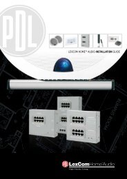
ADELAIDE<br />
2ANCOM3<br />
2ANCOM4 or<br />
2ANCOM6<br />
Port Gawler<br />
Outer Harbour<br />
Largs Bay<br />
Ethelton<br />
Port Adelaide<br />
Port Noarlunga<br />
Glenelg<br />
Hallett Cove<br />
Maslin Beach<br />
2AN 2ANUY12WB or<br />
2ANUY20WB<br />
(Multiple Outlets)<br />
2ANV2WB +<br />
2ANUY12WB<br />
(Requires Diplexer<br />
refer to page 43)<br />
Brighton<br />
St Kilda<br />
Marino<br />
Reynella<br />
Morphett Vale<br />
Virginia<br />
Adelaide<br />
Penfield<br />
Enfield<br />
Malvern<br />
Lynton<br />
Salisbury<br />
Parafield<br />
Elizabeth<br />
Cherry Gardens<br />
Clarendon<br />
McLaren Vale<br />
The Range<br />
Paradise<br />
Skye<br />
Stirling<br />
Yattalunga<br />
One Tree Hill<br />
Greenwith<br />
Upper Hermitage<br />
Houghton<br />
Montacute<br />
Hahndorf<br />
Echunga<br />
Lobethal<br />
Woodside<br />
Williamstown<br />
LOCATION GUIDES<br />
69
LOCATION GUIDES<br />
70<br />
<strong>Clipsal</strong> <strong>TV</strong> <strong>Cabling</strong> <strong>Solutions</strong><br />
MELBOURNE<br />
2ANCOM3<br />
2ANCOM4<br />
2ANUPA2<br />
2ANUY18/5
SYDNEY<br />
2ANCOM3<br />
Inner city Kings Cross<br />
translator line-of-sight use<br />
2ANUPA1 or 2ANUX43<br />
2ANCOM4 or<br />
2ANYV10 +2ANUY20WB<br />
(Requires Diplexer<br />
refer to page 43)<br />
2ANCOM6 or<br />
2ANVY10 + 2ANUX91<br />
(Requires Diplexer<br />
refer to page 43)<br />
2ANUY20WB<br />
2ANUPA2<br />
LOCATION GUIDES<br />
71
LOCATION GUIDES<br />
72<br />
<strong>Clipsal</strong> <strong>TV</strong> <strong>Cabling</strong> <strong>Solutions</strong><br />
NEWCASTLE<br />
2ANCOMD14WB<br />
2ANCOMD14WB<br />
+ Masthead Amplifier<br />
2ANCOM2NEW<br />
For Nelson Bay,<br />
call <strong>Clipsal</strong> for options<br />
2ANUY12WB<br />
2ANUY20WB<br />
2ANUPA2
BRISBANE<br />
2ANCOM3<br />
2ANCOM4<br />
2ANCOM6<br />
LOCATION GUIDES<br />
73
LOCATION GUIDES<br />
74<br />
<strong>Clipsal</strong> <strong>TV</strong> <strong>Cabling</strong> <strong>Solutions</strong><br />
SOUTH QUEENSLAND<br />
2ANCOM3 or<br />
2ANCOM4<br />
(Multiple Outlets)<br />
2ANUY12WB or<br />
2ANUY20WB<br />
(Multiple Outlets)<br />
2ANUPA2<br />
2ANCOMD14WB or<br />
2ANVY10 + 2ANUY20WB<br />
(Requires Diplexer<br />
refer to page 43)
PERTH<br />
2ANCOM3<br />
2ANCOM4<br />
2ANCOM6<br />
Two Rocks<br />
Scarborough<br />
Mt Claremont<br />
Peppermint Grove<br />
Fremantle<br />
Garden Island<br />
Rockingham<br />
Dawesville<br />
Quinns Rocks<br />
Joondalup<br />
Malaga<br />
Perth<br />
Bullsbrook<br />
Kalamunda<br />
Wungong<br />
Oldbury<br />
Mandurah<br />
Blythewood<br />
Red Hill<br />
Midland<br />
Piesse Brook<br />
Cardup<br />
Chidlow<br />
Reservoir<br />
Canning Mills<br />
LOCATION GUIDES<br />
75
When it comes to antenna installation, the choice is clear<br />
Product of <strong>Clipsal</strong> Australia Pty Ltd<br />
A member of the Schneider Electric Group<br />
Head Offi ce<br />
12 Park Terrace, Bowden<br />
South Australia 5007<br />
Telephone (08) 8269 0511<br />
Facsimile (08) 8340 1724<br />
Internet clipsal.com<br />
E-Mail plugin@clipsal.com.au<br />
National Customer Service Enquiries:<br />
1300 2025 25<br />
National Customer Service Facsimile:<br />
1300 2025 56<br />
International Enquiries<br />
International Sales and Marketing<br />
Telephone + 61 8 8269 0587<br />
Facsimile + 61 8 8340 7350<br />
E-Mail export@clipsal.com.au<br />
New Zealand<br />
<strong>Clipsal</strong> Industries (NZ) Ltd<br />
Telephone (09) 576 3403<br />
Facsimile (09) 576 1015<br />
E-Mail headoffi ce@clipsal.co.nz<br />
Customer Service<br />
Free Fax (0508) 250 305<br />
Auckland/Mobile Phone (09) 572 0014<br />
Free Phone (0508) CLIPSAL<br />
2547725<br />
You can fi nd this brochure and many others<br />
online in PDF format at: clipsal.com<br />
Follow the links off the home page or access<br />
the following page directly:<br />
clipsal.com/wat_lib_pdf.cfm<br />
<strong>Clipsal</strong> Australia Pty Ltd reserves the right to change<br />
specifi cations, modify designs and dis con tin ue items<br />
without incurring obligation and whilst every effort is<br />
made to ensure that descriptions, specifi cations and<br />
other in for ma tion in this catalogue are correct, no<br />
warranty is given in respect thereof and the company<br />
shall not be liable for any error therein.<br />
© <strong>Clipsal</strong> Australia Pty Ltd.<br />
CLIPCOM <strong>11954</strong> Aug 2007 The identified trademarks and copyrights are the property of <strong>Clipsal</strong> Australia Pty Ltd unless otherwise noted.<br />
D2-004<br />
O/N <strong>11954</strong>