technical specification for steel dry cargo container 20 - Steinecker ...
technical specification for steel dry cargo container 20 - Steinecker ...
technical specification for steel dry cargo container 20 - Steinecker ...

You also want an ePaper? Increase the reach of your titles
YUMPU automatically turns print PDFs into web optimized ePapers that Google loves.
TECHNICAL SPECIFICATION<br />
FOR<br />
STEEL DRY CARGO CONTAINER<br />
<strong>20</strong>’ x 8’ x 9’6” High Cube<br />
I N D E X<br />
Section Title Page<br />
1 General 2<br />
2 Dimensions and Ratings 4<br />
3 Materials 5<br />
4 Construction 6<br />
5 Surface preservation 11<br />
6 Markings 12<br />
7 Testing and Inspections 13<br />
8 Guarantee 14<br />
Stand Dez. <strong>20</strong>12<br />
<strong>Steinecker</strong> Containerhandel freecall: 0800 - 78 34 63 25 37 - www.steinecker-<strong>container</strong>.de<br />
63452 Hanau · Donaustraße 10 · Tel.: (06181) 180 40 0 · Fax (06181) 180 40 110<br />
NL Waldheim: 04736 Waldheim · Hauptstr. 86 · Tel.: (06181) 180 40 131 · Fax: (06181) 180 40 130
1. General<br />
1.1 Scope<br />
This <strong>specification</strong> will cover the design, construction, materials, testing and inspection<br />
per<strong>for</strong>mances of <strong>20</strong>’ x 8’ x 9’6” type <strong>steel</strong> <strong>dry</strong> <strong>cargo</strong> <strong>container</strong>s. These <strong>container</strong>s<br />
specified herein will be manufactured under strict quality control by manufacturer and<br />
be approved by the classification society or agency.<br />
1.2 Operational environment<br />
The <strong>container</strong> will be designed and constructed <strong>for</strong> carriage of general <strong>cargo</strong> by<br />
marine (on or below deck), road and rail throughout the world. All materials used in<br />
the construction will be to withstand extremes of temperature range from -40OC (-<br />
40OF) to +70OC (+158OF) without effect on the strength of the basic structure and<br />
watertightness.<br />
1.3 Standards and Regulations<br />
The <strong>container</strong> will satisfy the following requirements and regulations, unless<br />
otherwise mentioned in this <strong>specification</strong>.<br />
1.3.1 ISO Container Standards<br />
ISO 668 -- Series 1 freight <strong>container</strong>s - Classification external dimensions and ratings<br />
[Amd. 1993 (E)]<br />
ISO 830 -- Terminology in relation to freight <strong>container</strong> (Amd. 1988)<br />
ISO 1161 -- Series 1 freight <strong>container</strong>s - Corner fittings Specification (Amd. 1990)<br />
ISO 1496-1 -- Series 1 freight <strong>container</strong>s - Specification and testing. part 1: General<br />
<strong>cargo</strong> <strong>container</strong>s <strong>for</strong> general purposes (Amd.2 - 1998) ISO 6346 -- Freight <strong>container</strong>s<br />
- coding, identification and marking - 1995(E)<br />
1.3.2 T.I.R. Certification<br />
All the <strong>container</strong>s will be certified and comply with “The Customs Convention on the<br />
International Transport of Goods under the cover of T.I.R. Carnets.” or “The Customs<br />
Convention on Containers.”<br />
1.3.3 C.S.C. Certification<br />
All the <strong>container</strong>s will be certified and comply with the requirements of the<br />
“International Convention <strong>for</strong> the Safe Containers.”<br />
1.3.4 T.C.T. Certification<br />
All exposed wooden components used <strong>for</strong> <strong>container</strong> will be treated to comply with the<br />
requirements of “Cargo Containers - Quarantine Aspects and Procedures” of the<br />
Commonwealth Department of Health, Australia.<br />
1.3.5 Classification society<br />
1
All the <strong>container</strong>s will be certified <strong>for</strong> design type and individually inspected by<br />
Classification society, CCS, BV, ABS, LR, or GL<br />
Note: CCS : China Classification Society (P.R.C)<br />
BV : Bureau Veritas (France)<br />
ABS : American Bureau of Shipping (USA)<br />
LR : Lloyd’s Register of Shipping (UK)<br />
GL : Germanischer Lloyd (Germany)<br />
1.4 Handling<br />
The <strong>container</strong> will be constructed to be capable of being handled without any<br />
permanent de<strong>for</strong>mation under the following conditions:<br />
a) Lifting, full or empty, at top corner fittings vertically by means of spreaders fitted<br />
with hooks, shackles or twistlocks.<br />
b) Lifting, full or empty, at bottom corner fittings using slings with terminal fittings at<br />
any angles between vertical and 45 degrees to the horizontal.<br />
c) Lifting, full or empty, at <strong>for</strong>klift pockets using <strong>for</strong>klift truck.<br />
1.5 Transportation<br />
The <strong>container</strong> will be constructed to be suitable <strong>for</strong> transportation in the following<br />
modes:<br />
a) Marine : In the ship cell guides of vessels, seven (7) high stacked.<br />
On the deck of vessels, four (4) high stacked and secured by vertical and diagonal<br />
wire lashings.<br />
b) Road : On flat bed or skeletal chassis, secured by twistlocks or equivalent at the<br />
bottom corner fittings.<br />
c) Rail : On flat cars or special <strong>container</strong> cars secured by twistlocks or equivalent at<br />
the bottom corner fittings.<br />
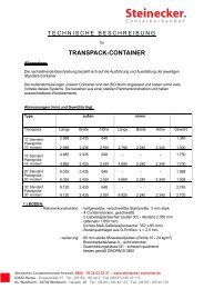
2. Dimensions and Ratings<br />
2.1 External Dimensions<br />
Length 6,058 + 0mm 19’10 ½” +0<br />
-6mm -1/4”<br />
Width 2,438 + 0mm 8’ +0<br />
-5mm -3/16”<br />
Height 2,896 + 0mm 9’6” +0<br />
-5mm -3/16”<br />
1) No part of the <strong>container</strong> will protrude beyond the external dimensions<br />
mentioned above.<br />
2
2) Maximum allowable differences between two diagonals on anyone of the<br />
following surfaces will be as follows:<br />
Roof, bottom and side diagonals : 13mm ½”<br />
Front and rear diagonals : 10mm 3/8”<br />
2.2 Internal Dimensions<br />
Length 5,898 + 0mm 19’ 4 13/64” +0<br />
-6mm -1/4”<br />
Width 2,350 + 0mm 7’ 8 33/64” +0<br />
-5mm -3/16”<br />
Height 2,695 + 0mm 8’10 3/32” +0<br />
-5mm -3/16”<br />
2.3 Door opening dimensions<br />
Width 2,338 + 0mm 7’ 8 3/64” +0<br />
-5mm -3/16”<br />
Height 2,585 + 0mm 8’ 5 49/64” +0<br />
-5mm -3/16”<br />
2.4 Internal cubic capacity (Nominal)<br />
37.4 cu.m 1,3<strong>20</strong> cu.ft<br />
2.5 Forklift pockets<br />
Width 360 mm 1’ 2 11/64”<br />
Height min. 115 mm 4 ½”<br />
Centre to centre 2,050 mm +/- 50 mm 6’ 9” +/-2”<br />
2.6 Ratings<br />
Max. Gross Weight (R) 30,480 kgs 67,<strong>20</strong>0 lbs<br />
Tare Weight (design) (T) 2,300 kgs 5,070 lbs<br />
Max. Payload (P) 28,180 kgs 62,130 lbs<br />
Tare Weight Tolerance 2%<br />
3. Materials<br />
3.1 General<br />
The following materials will be used in the construction of <strong>container</strong>s.<br />
3
3.2 Part <strong>specification</strong><br />
Parts Materials by JIS<br />
1) Roof panels<br />
Door panels<br />
Side panels<br />
Front panels<br />
Bottom side rails<br />
Cross members<br />
Upper & lower plates of <strong>for</strong>klift pockets<br />
Rear corner posts (outer)<br />
Door sill<br />
Door header (upper & lower)<br />
Door horizontal frames<br />
Door vertical frames<br />
Top side rails<br />
Front corner posts<br />
Front bottom end rail<br />
Front top end rail<br />
Anti-Corrosive Steel: CORTEN A,<br />
SPA-H, B480 or equivalent<br />
Y.P. : 35 kg/sq. mm<br />
T.S. : 49 kg/sq. mm<br />
2) Rear corner posts (inner)<br />
Rolled high tensile <strong>steel</strong>: SM490A<br />
or equivalent<br />
Y.P. : 33 kg/sq. mm<br />
T.S. : 50 kg/sq. mm<br />
3) Floor centre rail Structural Steel: SS400<br />
Y.P. : 25 kg/sq.mm<br />
T.S. : 41 kg/sq.mm<br />
4) Door locking bars Structural <strong>steel</strong> round pipe: STK41<br />
Y.P. : 24 kg/sq. mm<br />
T.S. : 41 kg/sq. mm<br />
5) Corner Fitting<br />
Casted weldable <strong>steel</strong>: SCW480<br />
Y.P. : 28 kg/sq. mm<br />
T.S. : 49 kg/sq. mm<br />
6) Locking gear cams and keepers Forged weldable <strong>steel</strong>: S<strong>20</strong>C<br />
Y.P. : 23 kg/sq. mm<br />
T.S. : 44 kg/sq. mm<br />
7) Door hinge pins<br />
Door gasket retainer<br />
Stainless <strong>steel</strong>: SUS304<br />
8) Door gasket EPDM<br />
9) Floor board Hardwood plywood, 19-ply<br />
10) Ventilator ABS resin labyrinth type<br />
4
• Note: Y.P. --- Yielding Point<br />
T.S. --- Tensile Strength<br />
4. Construction<br />
4.1 General<br />
4.1.1 The <strong>container</strong> will be constructed with <strong>steel</strong> frames, fully vertical-corrugated<br />
<strong>steel</strong> sides and front wall, horizontal-corrugated <strong>steel</strong> double doors at rear end,<br />
die-stamped <strong>steel</strong> roof and corner fittings.<br />
4.1.2 All welds of exterior including the base frames will be continuous welding<br />
using CO2 gas, but inner part of each bottom side rail will be fastened by staggered<br />
stitch welding.<br />
4.1.3 Interior welds - when needed - will be stitched with a minimum bead length of<br />
15mm.<br />
4.1.4 Gaps between adjacent components to be welded will not exceed 3mm or the<br />
half thickness of the parts being welded.<br />
4.1.5 Chloroprene sealant is to be applied at periphery of floor surface and inside<br />
unwelded seams, butyl sealant is used to caulk at invisible seam of floor joint area<br />
and between door gasket and frame.<br />
4.1.6 The wooden floor will be fixed to the base frames by zinc plated self-tapping<br />
screws.<br />
4.2 Protrusion<br />
4.2.1 The plane <strong>for</strong>med by the lower faces of the bottom side rails and all transverse<br />
members shall be positioned by 12.5mm +5/-1.5mm above the plane <strong>for</strong>med by<br />
the lower faces of the bottom corner fittings.<br />
4.2.2 The top corner fittings are to protrude a minimum of 6mm above the highest<br />
point of the roof.<br />
4.2.3 The outside faces of the corner fittings will protrude from the outside faces of<br />
the corner posts by minimum 4mm <strong>for</strong> side structure and 4mm <strong>for</strong> front end<br />
structure.<br />
4.2.4 The outside faces of the corner fittings will protrude from side wall by nominal<br />
8mm and from the outside face of the end wall by 8mm.<br />
4.2.5 Under maximum payload, no part of the <strong>container</strong> will protrude below the<br />
plane <strong>for</strong>med by the lower faces of the bottom corner fittings at the time of<br />
maximum deflection.<br />
4.2.6 Under 1.8 x maximum gross weight, no part of the <strong>container</strong> will protrude more<br />
than 6.0mm below the plane <strong>for</strong>med by the lower faces of the bottom corner<br />
fittings at the time of maximum deflection.<br />
4.3 Corner fittings<br />
The corner fittings will be designed in accordance with ISO 1161 (Amd.1990) and<br />
manufactured at the works approved by classification society.<br />
5
4.4 Base frame structure<br />
Base frame will be composed of two (2) bottom side rails, a set of <strong>for</strong>klift pockets and<br />
totally eighteen (18) cross members.<br />
4.4.1 Bottom side rail<br />
Each bottom side rail is built of 48x158x30x4.5mm thick cold-<strong>for</strong>med channel section<br />
<strong>steel</strong> made in one piece. The floor guide rails of 3.0mm thick pressed angle section<br />
<strong>steel</strong> are provided to the bottom side rails by staggered stitch welding.<br />
The lower flange of the bottom side rail is outward so as to facilitate easy removal of<br />
the cross members during repair and of less susceptible corrosion.<br />
Rein<strong>for</strong>cement plates are to be made of 4.0mm thick, flat <strong>steel</strong> plates. The plates are<br />
welded to bottom corner fitting.<br />
4.4.2 Forklift pockets<br />
Each <strong>for</strong>klift pocket is built of 3.0mm thick full depth flat <strong>steel</strong> top plate and two <strong>20</strong>0<br />
mm deep x 6.0 mm thick flat lower end plates between two channel section cross<br />
members.<br />
The one set of <strong>for</strong>klift pockets is designed in accordance with ISO requirements.<br />
4.4.3 Cross member<br />
The cross members are made of pressed channel section <strong>steel</strong> with a dimension of<br />
45x122x45x4.0mm <strong>for</strong> the normal areas and 75x122x45x4.5mm <strong>for</strong> the floor butt<br />
joints. The cross members are placed fully to withstand floor strength and welded to<br />
each bottom side rail.<br />
4.5 Flooring<br />
The floor will consist of six pieces plywood boards, floor centre rail, and self-tapping<br />
screws.<br />
4.5.1 Floor<br />
The wooden floor to be constructed with 28mm thick 19-ply hardwood plywood<br />
boards are laid longitudinally on the transverse members between the <strong>steel</strong> floor<br />
centre rail of 4.0mm thick flat bar and the 3.0mm thick pressed angle section <strong>steel</strong><br />
floor guide rails stitched welded to the bottom side rails.<br />
The floorboards are tightly secured to each transverse member by self-tapping<br />
screws, and all butt joint areas and peripheries of the floorboards are caulked with<br />
sealant.<br />
1) Wood species : Apitong or Keruing<br />
2) Glue : Phenol-<strong>for</strong>maldehyde resin.<br />
3) Treatment :<br />
a) Preservative: BASILEUM SI-84 or others.<br />
6
) In accordance with Australian Health Department Regulations. Average<br />
moisture content will be 12% be<strong>for</strong>e installation.<br />
4.5.2 Self-tapping screw<br />
Each floor board is fixed to the transverse members by zinc plated self-tapping<br />
screws that are 8.0mm dia. shank x 16mm dia. head x 45mm length, and fastened by<br />
four screws per cross member but five screws at joint areas. Screw heads are to be<br />
countersunk through about 2mm below the floor top surface.<br />
4.6 Rear frame structure<br />
The rear frame will be composed of one door sill, two corner posts, one door header<br />
and four corner fittings, which will be welded together to make the door-way.<br />
4.6.1 Door sill<br />
The door sill to be made of a 4.5mm thick pressed open section <strong>steel</strong> is rein<strong>for</strong>ced by<br />
four internal gussets of a 4.0mm thick at the back of each locking cam keeper<br />
location. The upper face of the door sill has a 10mm slope <strong>for</strong> better drainage. A<br />
<strong>20</strong>0 x 75mm section is cut out at each end of the door sill and rein<strong>for</strong>ced by a <strong>20</strong>0 x<br />
75mm channel <strong>steel</strong> as a protection against handling equipment damages.<br />
4.6.2 Rear corner post<br />
Each rear corner post of hollow section is fabricated with pressed, 6.0mm thick, <strong>steel</strong><br />
outer part and 40x113x12mm hot-rolled channel section <strong>steel</strong> inner part, which are<br />
welded continuously together to ensure a maximum width of the door opening and to<br />
give a sufficient strength against stacking and racking <strong>for</strong>ces.<br />
Four (4) sets of hinge pin lugs are welded to each rear corner post.<br />
4.6.3 Door header<br />
The door header is constructed with a 4.0mm thick pressed “U” section <strong>steel</strong> lower<br />
part having four internal gussets at the back of each locking cam keeper location and<br />
a 3.0mm thick pressed <strong>steel</strong> upper part, which are <strong>for</strong>med into box section by<br />
continuous welding.<br />
4.7 Door<br />
4.7.1 Each <strong>container</strong> will have double wing doors at rear end frame, and each door<br />
will be capable of swinging approximately 270 degrees.<br />
4.7.2 Each door is constructed with pressed, 3.0mm thick, channel section <strong>steel</strong><br />
horizontal frames <strong>for</strong> the top and bottom, 100x50x2.3mm and 100x50x3.2mm<br />
rectangular hollow section vertical frames <strong>for</strong> the post side and centre side of door<br />
respectively, 2.0mm thick horizontally corrugated <strong>steel</strong> door panel, which are<br />
continuously welded within frames.<br />
4.7.3 Two sets of galvanized locking assemblies which is the same model with “BE-<br />
2566 Modified” with <strong>steel</strong> handles are fitted to each door wing using high tensile<br />
7
zinc plated <strong>steel</strong> bolts according to TIR requirements. Locking bar retainers are<br />
fitted with nylon bushings at the top, bottom and intermediate bracket.<br />
Locking gears should be assembled after painting and not to be painted.<br />
4.7.4 The left-hand door can not be opened without opening the right-hand door<br />
when the <strong>container</strong> is sealed in accordance with TIR requirements.<br />
4.7.5 The door hold-back of nylon rope is provided to the centre locking bar on each<br />
door and a hook of <strong>steel</strong> bar is welded to each bottom side rail.<br />
4.7.6 Each door is suspended by four hinges being provided with stainless <strong>steel</strong><br />
pins, self-lubricating nylon bushings and brass washers, which are placed at the<br />
hinge lugs of the rear corner posts.<br />
4.7.7 The door gasket made of an extruded triple lip type (J-type) EPDM rubber is<br />
installed to the door peripheral frames with stainless <strong>steel</strong> gasket retainers and<br />
fastened by stainless <strong>steel</strong> blind rivets at a pitch of 150mm. The door gasket must<br />
be caulked with butyl sealant be<strong>for</strong>e installation to the door frames.<br />
4.8 Roof structure<br />
The roof will be constructed with five five-corrugated (die-stamped) <strong>steel</strong> panels and<br />
four corner protection plates.<br />
4.8.1 Roof panel<br />
The roof panel is constructed with 2.0mm thick die-stamped <strong>steel</strong> sheets having<br />
about 6.0mm upward smooth camber, which are welded together to <strong>for</strong>m one panel<br />
and continuously welded to the top side rails and top end rails. All overlapped joints<br />
of inside unwelded seams are caulked with chloroprene sealant.<br />
4.8.2 Protection plate<br />
Each corner of the roof in the vicinity of top corner fitting is rein<strong>for</strong>ced by 3.0mm thick<br />
rectangular <strong>steel</strong> plate to prevent the damage caused by mishandling of lifting<br />
equipment.<br />
4.9 Top side rail<br />
Each top side rail is made of a 60x60x3.0mm thick square hollow section <strong>steel</strong>.<br />
4.10 Side wall<br />
The trapezium section side wall is constructed with 1.6mm thick fully vertically<br />
continuouscorrugated <strong>steel</strong> panels at the intermediate area and 2.0mm thick fully<br />
vertically continuouscorrugated <strong>steel</strong> panels at both ends which are butt welded<br />
together to <strong>for</strong>m one panel and continuously welded to the side rails and corner<br />
posts. All overlapped joints of inside are caulked with chloroprene sealant.<br />
4.11 Front structure<br />
8
Front end structure will be composed of one bottom end rail, two corner posts, one<br />
top end rail, four corner fittings and an end wall, which are welded together.<br />
4.11.1 Bottom end rail<br />
The bottom end rail to be made of a 4.0mm thick pressed open section <strong>steel</strong> is<br />
rein<strong>for</strong>ced by three internal gussets. A <strong>20</strong>0x75mm is cut out at each end of the<br />
bottom end rail and rein<strong>for</strong>ced by a <strong>20</strong>0x75mm channel <strong>steel</strong> as a protection against<br />
handling equipment damages.<br />
4.11.2 Front corner post<br />
Each corner post is made of 6.0mm thick pressed open section <strong>steel</strong> in a single<br />
piece, and designed to give a sufficient strength against stacking and racking <strong>for</strong>ces.<br />
4.11.3 Top end rail<br />
The top end rail is constructed with 60x60x3.0mm thick square hollow section <strong>steel</strong> at<br />
lower part and 3.0mm thick pressed <strong>steel</strong> at upper part.<br />
4.11.4 Front wall<br />
The trapezium section front wall is constructed with 2.0mm thick vertically corrugated<br />
<strong>steel</strong> panels, butt welded together to <strong>for</strong>m one panel, and continuously welded to<br />
front end rails and corner posts. All overlapped joints of inside are caulked with<br />
chloroprene sealant.<br />
4.12 Special feature<br />
4.12.1 Customs seal provisions<br />
Customs seal and padlock provisions are made on each locking handle retainer to<br />
cover the sealed area in accordance with TIR requirements.<br />
4.12.2 Lashing fittings<br />
Five (5) lashing hoop rings are welded to each top and bottom side rail at recessed<br />
corrugations of side panels but not extruded any <strong>cargo</strong> space (total <strong>20</strong> rings). Each<br />
lashing point is designed to provide a “1,500 kgs pull load in any direction” without<br />
any permanent de<strong>for</strong>mation of lashing ring and surrounding area.<br />
Three (3) lashing rods are welded to each corner post. Each lashing rod on the<br />
corner post is designed to provide a “1,500 kgs pull load in any direction” without any<br />
permanent de<strong>for</strong>mation.<br />
4.12.3 Shoring slot<br />
A shoring slot, having a size of 60 mm width x 40 mm depth is provided on each rear<br />
corner post so that 2 ¼” thick battens can be arranged to be able to prevent doors<br />
from damage due to shifting <strong>cargo</strong>.<br />
9
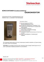
4.12.4 Ventilator<br />
Each <strong>container</strong> will have two small plastic ventilators of labyrinth type. Each<br />
ventilator is fixed to the right-hand upper part of each side wall by three 5.0mm dia.<br />
<strong>steel</strong> huck bolts in accordance with TIR requirements after <strong>dry</strong>ing of top coating, and<br />
caulked with silicone sealant around the entire periphery except bottom to prevent<br />
the leakage of water.<br />
5. Surface preservation<br />
5.1 Surface preparation<br />
1) All <strong>steel</strong> surfaces - prior to <strong>for</strong>ming or after - will be fully abrasive shot blasted<br />
con<strong>for</strong>ming to Swedish Standard SA2 ½ to remove all rust, dirt, mill scale and all<br />
other <strong>for</strong>eign materials.<br />
2) All door hardware will be hot-dipping zinc galvanized with approximately 75<br />
microns thickness.<br />
3) All fasteners such as self-tapping screws and bolts, nuts, hinges, cam keepers,<br />
lashing fittings will be electro-galvanized with approximately 13 microns thickness.<br />
5.2 Primer coating<br />
5.2.1 Prior to assembly<br />
All <strong>steel</strong> surfaces will be coated with 10-15 microns thick two-pack polyamide cured<br />
zinc rich epoxy primer immediately after shot blasting, and then dried up in <strong>dry</strong>ing<br />
room.<br />
5.2.2 After assembly<br />
1) All weldments will be shot blasted to remove all welding fluxes, spatters, burnt<br />
primer coatings caused by welding heat, and other <strong>for</strong>eign materials.<br />
Then all blasted weldments will be coated with zinc rich epoxy primer.<br />
2) Exterior of assembled <strong>container</strong> will be coated again 10 microns with zinc rich<br />
epoxy primer and again 35-40 microns epoxy primer prior to top coating.<br />
5.3 Top coating<br />
1) After <strong>dry</strong>ing of primer, exterior of <strong>container</strong> will be coated again with high build top<br />
paint and interior will be coated again with polyamide cured epoxy resin based<br />
high build coating.<br />
2). The <strong>dry</strong> film thickness of top coating will be 55-60 microns <strong>for</strong> the exterior and 50<br />
microns<br />
<strong>for</strong> the interior<br />
5.4 Under coating<br />
After completion of flooring, all the understructures and floor will be coated with<br />
minimum 230 microns <strong>dry</strong> film thickness bituminous coating.<br />
10
5.5 The total <strong>dry</strong> film will be (microns):<br />
EXT. INT. BASE<br />
Zinc rich primer <strong>20</strong>-25 <strong>20</strong>-25 <strong>20</strong>-25<br />
Epoxy primer 35-40<br />
Epoxy high build coating 50<br />
Acrylic coating 55-60<br />
Bitumen 230<br />
Total 110 70 250<br />
Roof 1<strong>20</strong><br />
6. Marking<br />
6.1 Arrangement<br />
The <strong>container</strong> will be marked in accordance with ISO, TCT, CSC and TIR<br />
requirements, owner’s marking <strong>specification</strong>s and other required regulations.<br />
6.2 Materials<br />
1) Decal : - Self-adhesive, high tensile PVC film <strong>for</strong> seven (7) years guarantee<br />
without peeling off, tenting or colour fading.<br />
2)Certification plate : 18-8 type stainless <strong>steel</strong> plates to be chemically etched by acid<br />
and treated by enamel.<br />
6.3 Specifications<br />
1) Identification plates such as consolidated data plate consisting of CSC, TIR and<br />
TCT will be riveted on the door permanently by stainless <strong>steel</strong> blind rivets. The<br />
entire periphery except underside will be caulked with sealant.<br />
2) The owner’s serial numbers and manufacturer’s serial numbers will be stamped<br />
into the top plane of rear lower corner fitting.<br />
7. Testing and Inspections<br />
7.1 Testing<br />
7.1.1 Prototype testing<br />
The prototype <strong>container</strong> to be manufactured in accordance with this <strong>specification</strong> will<br />
be tested by manufacturer under the supervision of classification society.<br />
Test items & loads Test methods<br />
A)<br />
Stacking<br />
Internal load : 1.8R-T<br />
11
Test load: 86,400kg/post<br />
Hydraulic cylinder load will be applied to each<br />
corner post through top corner fittings.<br />
Offset: 25.4 mm lateral<br />
38.0 mm longitudinal<br />
B) Lifting (from top corner fittings)<br />
Internal load : 2R-T<br />
Lifting vertically.<br />
Time duration : 5 minutes<br />
C) Lifting (from bottom corner fittings)<br />
Internal load : 2R-T<br />
Lifting 45 degree to the horizontal.<br />
Time duration : 5 minutes<br />
D)<br />
Lifting (<strong>for</strong> <strong>for</strong>klift pockets)<br />
Internal load : 1.6R-T<br />
Lifting by horizontal bars.<br />
Bar length : 1,828mm<br />
Bar width : <strong>20</strong>0mm<br />
E) Restraint (longitudinal)<br />
Internal load : R-T<br />
Test load : 2R<br />
Hydraulic cylinder load will be applied to the<br />
bottom side rails.<br />
F)<br />
Floor strength<br />
Test load : 7,260 kgs<br />
(16,000 lbs)<br />
Use of a special truck.<br />
Total contact area: 284 sq. cm<br />
Wheel width : 180 mm<br />
Wheel centre : 760 mm<br />
G) Wall strength (front)<br />
Test load : 0.4(R-T)=0.4P<br />
Compressed air bag will be used.<br />
H) Wall strength (side)<br />
Test load : 0.6(R-T)=0.6P<br />
Compressed air bag will be used on one side only.<br />
I) Wall strength (door)<br />
Test load : 0.4(R-T)=0.4P<br />
Same as front wall strength test.<br />
J) Roof strength (weakest part)<br />
Test load : 300 kgs<br />
Applied area will be 600x300mm longitudinal and transverse.<br />
K) Racking (transverse)<br />
Test load : 15,240 kgs<br />
12
Hydraulic cylinder load will be applied to the header rail through top corner fittings.<br />
L) Racking (longitudinal) Hydraulic cylinder load will be applied to the top<br />
Test load : 7,6<strong>20</strong> kgs side rail through top corner fitting on one side only.<br />
Two times <strong>for</strong> pulling and pushing.<br />
M) Operation of door<br />
After completion of test, the operation of doors, locks, hinges, etc. will be checked.<br />
N) Dimensions and weight<br />
After completion of test, the dimensions and weight will be checked.<br />
O) Weatherproofness Inside dia. of nozzle : 12.5mm<br />
Distance : 1.5 m<br />
Speed : 100 mm/sec.<br />
Pressure : 1 kg/sq. cm<br />
Note: R Maximum Gross Weight T Tare Weight P Maximum Payload<br />
8. Guarantee<br />
8.1 Structure<br />
All the <strong>container</strong>s shall be guaranteed by manufacturer to be free from defects in<br />
materials, workmanship and structure <strong>for</strong> a period of one (1) year, from the date of<br />
acceptance of the <strong>container</strong> by the buyer.<br />
8.2 Painting<br />
8.2.1 The paint system coated on the <strong>container</strong> surface shall be guaranteed<br />
to be free from corrosion and failure <strong>for</strong> a period of five (5) years, from the<br />
date of acceptance of the <strong>container</strong> by the buyer.<br />
8.2.2 Corrosion is defined as rusting which exceeds RE3 (European Scale of<br />
degree of Rusting) on at least ten (10) percent of the total <strong>container</strong> surface,<br />
excluding that resulting from impact or abrasion damage, contact with<br />
solvents or corrosive chemicals and abnormal use.<br />
8.2.3 If the corrosion exceeds RE3 as defined above within the guarantee<br />
period, inspection of the corrosion shall be carried out by the buyer, <strong>container</strong><br />
manufacturer and paint manufacturer to detect the cause. As the result of the<br />
inspection, if it is mutually agreed and accepted that the corrosion has<br />
caused <strong>for</strong> the defective paint quality and/or poor workmanship, <strong>container</strong><br />
manufacturer and/or paint manufacturer shall correct the defect on their<br />
accounts.<br />
8.3 Decals<br />
Decals applied on the <strong>container</strong> shall be guaranteed <strong>for</strong> a period of seven (7) years<br />
without peeling off, tenting or colour fading if decals are supplied by manufacturer.<br />
13
Manufacturer shall not be liable <strong>for</strong> any consequential damage or expenses<br />
occasioned by any defects <strong>for</strong> whatsoever reason or any loss of time due to repair or<br />
correction.<br />
Stand Dez. <strong>20</strong>12<br />
<strong>Steinecker</strong> Containerhandel freecall: 0800 - 78 34 63 25 37 - www.steinecker-<strong>container</strong>.de<br />
63452 Hanau · Donaustraße 10 · Tel.: (06181) 180 40 0 · Fax (06181) 180 40 110<br />
NL Waldheim: 04736 Waldheim · Hauptstr. 86 · Tel.: (06181) 180 40 131 · Fax: (06181) 180 40 130<br />
*****