Medium Voltage Catalog - DSG-Canusa
Medium Voltage Catalog - DSG-Canusa
Medium Voltage Catalog - DSG-Canusa

You also want an ePaper? Increase the reach of your titles
YUMPU automatically turns print PDFs into web optimized ePapers that Google loves.
<strong>Medium</strong> <strong>Voltage</strong> <strong>Catalog</strong><br />
Insulate. Seal. Protect.
Welcome to the <strong>DSG</strong>-<strong>Canusa</strong> Product <strong>Catalog</strong><br />
The <strong>DSG</strong>-<strong>Canusa</strong> catalog includes information on all major products that we carry to service Electrical/<br />
Utility, Industrial, Automotive, Electronics, Military/Aerospace and Communications applications.<br />
The catalog is arranged into the following sections to help you quickly find information and compare<br />
products:<br />
Selection<br />
• A quick comparison of products within the major item classes to facilitate selection<br />
Low <strong>Voltage</strong> Products<br />
• Our world class medium and heavy wall heat shrink as well as many specialized<br />
products and kits for low voltage electrical applications<br />
<strong>Medium</strong> <strong>Voltage</strong> Products<br />
• Detailed specifications on medium voltage terminations and joints<br />
Equipment Insulation<br />
• Insulation products for bus bars and industrial equipment<br />
Single Wall<br />
• Thin wall polyolefin heat shrink tubing for wire harnesses and general purpose<br />
insulation and protection<br />
Dual Wall (adhesive lined)<br />
• Thin wall adhesive lined polyolefin heat shrink tubing for wire harnesses and<br />
general purpose sealing and protection<br />
Automotive<br />
• Custom designed heat shrink solutions for splice sealing and water blocking<br />
Specialty Non-polyolefin<br />
• Thin wall non-polyolefin heat shrink products for demanding applications<br />
Communications<br />
• Innovative products for cable, telecom and wireless<br />
Reference<br />
• Useful tools for product cross reference and quick selection
<strong>DSG</strong>-<strong>Canusa</strong>, a division of ShawCor<br />
<strong>DSG</strong>-<strong>Canusa</strong> is a division of ShawCor, a publicly traded growth oriented energy services company with<br />
revenues of more than 1 billion CDN annually. ShawCor operates globally through seven divisions<br />
to provide products and services to the pipeline and industrial market segments. ShawCor has<br />
manufacturing and service facilities throughout the world.<br />
<strong>DSG</strong>-<strong>Canusa</strong>, A Global Success<br />
<strong>DSG</strong>-<strong>Canusa</strong> provides electrical and mechanical insulation solutions for the Electrical/Utility,<br />
Communications, Automotive and Electronics markets. In operation since 1981, <strong>DSG</strong>-<strong>Canusa</strong> has<br />
experienced double digit growth and is one of the largest heat shrink manufacturers in the world.<br />
Manufacturing and Distribution<br />
United States Canada United Kingdom<br />
Germany China<br />
Research and Development<br />
Canada Germany China<br />
Sales and Satellite Distribution<br />
Worldwide<br />
Unique Solutions for Custom Applications<br />
<strong>DSG</strong>-<strong>Canusa</strong> is the complete source for heat shrink products and related technology. Product offering<br />
includes polyolefin, flurorpolymer, elastomer and PVC heat shrink based materials in thin, medium<br />
and heavy walled tubing as well as heat shrink accessories and equipment. New products are<br />
continuously being developed to meet industry requirements. Moreover, a commitment to develop<br />
unique solutions for customer applications has earned <strong>DSG</strong>-<strong>Canusa</strong> a reputation of excellence in<br />
Customer satisfaction.
Table of Contents<br />
<strong>Medium</strong> <strong>Voltage</strong> Products<br />
Heat Shrink <strong>Medium</strong> <strong>Voltage</strong> Termination Kits<br />
CT Series ............................................................................................................................................................................... 8<br />
Single and three core shielded and non-shielded cables<br />
CT 50N Series ..................................................................................................................................................................... 10<br />
1/C and 3/C, 5 - 8 kV XLPE and EPR non-shielded cables<br />
CT UD Series ....................................................................................................................................................................... 12<br />
Single core, 15 - 35 kV bare and jacketed cables<br />
CT G Series ......................................................................................................................................................................... 14<br />
Single core, 5 - 35 kV XLPE and EPR power cables<br />
CT 3G Series ....................................................................................................................................................................... 16<br />
Three core, 5 - 35 kV XLPE and EPR power cables<br />
CT LC Series ........................................................................................................................................................................ 18<br />
Single core, 15 - 35 kV longitudinally corrugated shielded cables<br />
Cold Shrink <strong>Medium</strong> <strong>Voltage</strong> Termination Kits<br />
TITAN G Series .................................................................................................................................................................... 20<br />
Single core, 5 - 15 kV XLPE and EPR shielded power cables<br />
TITAN UD Series ................................................................................................................................................................. 22<br />
Single core, 15 kV XLPE and EPR bare and jacketed cables<br />
TITAN NS Series .................................................................................................................................................................. 24<br />
Single core, 5-8 kV XLPE and EPR non-shielded cables<br />
<strong>Medium</strong> <strong>Voltage</strong> Joint Kits<br />
CJ Series ............................................................................................................................................................................. 26<br />
Single and three core shielded and non-shielded cables<br />
CJ N50 Series ...................................................................................................................................................................... 28<br />
1/C, 3/C and 3/C armored, 5 - 8 kV XLPE and EPR non-shielded cables<br />
CJ 10 Series ........................................................................................................................................................................ 30<br />
Single core, 15 - 35 kV XLPE and EPR bare and jacketed cables<br />
CJ R10 Series ...................................................................................................................................................................... 32<br />
Single core, 15 - 35 kV bare and jacketed cables<br />
CJ 20 Series ........................................................................................................................................................................ 34<br />
Single core, 5 - 35 kV XLPE and EPR shielded power cables<br />
CJ 320 Series ...................................................................................................................................................................... 36<br />
Three core, 5 - 35 kV XLPE and EPR shielded power cables<br />
CJ 3A20 Series .................................................................................................................................................................... 38<br />
Three core, 5 - 35 kV XLPE and EPR shielded power cables<br />
CJ LC Series ......................................................................................................................................................................... 40<br />
Single core, 15 - 35 kV XLPE and EPR longitudinally corrugated Type LC cables<br />
CJ 80 Series ........................................................................................................................................................................ 42<br />
Single core, for splicing PILC or VCLC to itself or to XLP or EPR cables<br />
CJT 80 Series ...................................................................................................................................................................... 44<br />
Trifurcating transition joints, 15 and 25 kV PILC or VCLC to 1/C XLP or EPR cables<br />
CJT 90 Series ...................................................................................................................................................................... 46<br />
Trifurcating joints, 3/C, 15 and 25 kV PILC or VCLC to 1/C PILC or VCLC cables<br />
CJ 390 Series ...................................................................................................................................................................... 48<br />
Straight joints for splicing 3/C, 15 and 25 kV PILC or VCLC to 3/C PILC or VCLC cables<br />
CLES 80 Series .................................................................................................................................................................... 50<br />
1/C, 15 and 25 kV live end seals<br />
CLES 390 Series .................................................................................................................................................................. 52<br />
3/C, 15 and 25 kV live end seals<br />
Cold Shrink <strong>Medium</strong> <strong>Voltage</strong> Joint Kits<br />
CSJ 10 Series ....................................................................................................................................................................... 54<br />
Single core, 15 kV XLPE and EPR bare and jacketed cables<br />
CSJ 20 Series ....................................................................................................................................................................... 56<br />
Single core, 15 kV XLPE and EPR shielded power cables
Kits and Accessories<br />
3/C Conversion Kits ............................................................................................................................................................ 58<br />
Termination and joint conversion kits<br />
Accessories and Hardware ................................................................................................................................................. 60<br />
CRSA, CFS, MESH, BRDM, CFGK, CPK, CTSR, Sealants and Tapes<br />
CTCH/CHGN ....................................................................................................................................................................... 62<br />
Propane torches and heat guns<br />
Low <strong>Voltage</strong> Products<br />
Heavy and <strong>Medium</strong> Wall Products<br />
CFHR ................................................................................................................................................................................... 66<br />
Heavy wall, high ratio cross-linked polyolefin tubing<br />
CFM .................................................................................................................................................................................... 68<br />
<strong>Medium</strong> wall cross-linked polyolefin<br />
CFW .................................................................................................................................................................................... 70<br />
Heavy wall cross-linked polyolefin tubing<br />
FCFW .................................................................................................................................................................................. 72<br />
Heavy wall, flame retardant cross-linked polyolefin tubing<br />
QuickWrap ......................................................................................................................................................................... 74<br />
Wraparound heat shrink sleeve<br />
CSS Series ........................................................................................................................................................................... 76<br />
Cold seal splice kit<br />
Specialty Products and Kits<br />
CAPL ................................................................................................................................................................................... 78<br />
Airport lighting kit<br />
CCAP-RL .............................................................................................................................................................................. 80<br />
<strong>Medium</strong> wall cross-linked polyolefin end cap<br />
CCAP-RL/FR ........................................................................................................................................................................ 82<br />
Heavy wall cross-linked polyolefin end cap<br />
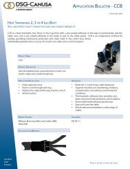
CCB .................................................................................................................................................................................... 84<br />
Cross-linked polyolefin cable breakout boot<br />
CMSK .................................................................................................................................................................................. 86<br />
Mining cable splice kit<br />
CRDW ................................................................................................................................................................................. 88<br />
Adhesive lined, wraparound cable repair sleeve<br />
CRDW CT ............................................................................................................................................................................ 90<br />
1 kV cable tap splice kit<br />
CRLS ................................................................................................................................................................................... 92<br />
Wraparound cable repair sleeve<br />
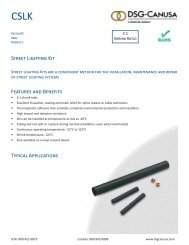
CSLK ................................................................................................................................................................................... 94<br />
Street lighting kit<br />
CTSB-2/CTSG-1 ................................................................................................................................................................... 96<br />
Black sealant tape/Grey butyl tape<br />
DV Tape .............................................................................................................................................................................. 98<br />
Adhesive lined cross-linked polyolefin tape<br />
UF Splice Kit ..................................................................................................................................................................... 100<br />
Underground feeder (UF) cable splice kit<br />
Equipment Insulation and Connection Products<br />
CBTM/CBTH ..................................................................................................................................................................... 104<br />
<strong>Medium</strong> voltage bus bar tubing<br />
CMVBT ............................................................................................................................................................................. 106<br />
<strong>Medium</strong> voltage bus bar tape<br />
CMTK Series ..................................................................................................................................................................... 108<br />
Motor lead termination kit<br />
Reference<br />
Raychem to <strong>DSG</strong>-<strong>Canusa</strong> Electrical Cross Reference ........................................................................................................ 110<br />
Quik_Select’r Cable Accessory Selection Guide ............................................................................................................... 112<br />
USA: 800.422.6872 Canada: 800.845.6808 www.dsgcanusa.com
<strong>Medium</strong> <strong>Voltage</strong> Products<br />
<strong>Medium</strong> voltage heat shrink and cold shrink products are used on electrical<br />
distribution cable networks and accessories, and other electrical equipment to<br />
provide the highest quality insulation solutions.<br />
Heat shrink and cold shrink solutions for power cable applications include cable<br />
terminations and splices to 35 kV. <strong>DSG</strong>-<strong>Canusa</strong>’s innovative products provide a<br />
cost effective alternative to hand applied tape, rubber moulded force-fit shapes,<br />
and resin based technology. The kits are factory designed and independently<br />
tested to the latest IEEE standards.<br />
USA: 800.422.6872 Canada: 800.845.6808 www.dsgcanusa.com 7
CT Series<br />
Insulate<br />
Seal<br />
Protect<br />
Heat shrink cable terminations for 1/C and 3/C, 5 kV to 35 kV shielded and non-shielded<br />
power cables for the electrical utility, commercial and industrial markets<br />
The CT series heat shrink cable terminations rated 5 kV through 35 kV are designed for single and three core, nonshielded,<br />
metal tape, drain wire shield, bare and jacketed concentric neutral and LC type shielded cables. The<br />
terminations use heat activated mastic seals that unequivocally bond to plastics and metal to provide excellent<br />
protection against moisture ingress. The electrical stresses at the semicon cutback point are controlled with the use<br />
of a proven, stress control tube and stress control sealant that provide a smooth, void-free interface and a redundant<br />
seal. CT series terminations are designed with a non-tracking outer insulating material that offers resistance to UV<br />
degradation and a self-cleaning outer surface that prevents build up of environmental contaminants to eliminate<br />
sources of tracking<br />
Features and Benefits<br />
• Fast, consistent installation means lower installed costs<br />
• Installation environment: use of torch adds flexibility to cable preparation in any climate<br />
• Heat activated seal ensures maximum protection against moisture ingress<br />
• Custom tailored with options to your exacting needs<br />
• Lightweight construction requires no additional support<br />
• Wide cable ranges for reduced inventory requirements<br />
• Tough abrasion resistant non-tracking outer covering<br />
• Slim profile allows installation in confined switch gear cubicles<br />
Standards<br />
• IEEE 48-1996, Class 1<br />
Test Reports<br />
The CT 080 series through CT 350 series terminations were tested to the<br />
requirements of IEEE 48-1996, Class 1 at an independent laboratory.<br />
Test reports are available as follows:<br />
• CT 080 series: HVS020075<br />
• CT 150 series: HVS020076<br />
• CT 250 series: HVS020077 and HVS020083<br />
• CT 350 series: HVS020078<br />
8
Heat Shrink, <strong>Medium</strong> <strong>Voltage</strong><br />
Cable Terminations<br />
Product Line<br />
CT Series<br />
• CT 50N Series: 5 kV through 8 kV non-shielded extruded dielectric (XLPE or EPR) fixed power cable terminations.<br />
Available as single core and three core configurations.<br />
Standard Packaging: CT 50N three, single core kits per box; or<br />
CT 50N3 one, three core kit per box<br />
• CT LC Series: 15 kV through 35 KV, longitudinally corrugated shield (LC), extruded dielectric (XLPE or EPR) fixed power<br />
cable, indoor and outdoor terminations<br />
Available as a single core kit packaged: one single core kit per box<br />
Comes complete with solder less external grounding kit<br />
Available with optional cable preparation/cleaning kit<br />
• CT UD Series: 15 kV through 35 kV, bare and jacketed concentric neutral, extruded dielectric (XLPE or EPR) underground<br />
distribution cable, indoor and outdoor terminations<br />
Available as single core kit packaged one single core kit per box<br />
Optional cable preparation/cleaning kit can be included<br />
• CT G Series: 5 kV through 35 kV, copper tape, drain wire, UniShield® and lead sheath shielded, extruded dielectric<br />
(XLPE or EPR) cable terminations<br />
Available in single core kits packaged three kits per box and as three core kits packaged as one, three core kit per<br />
box<br />
Connectors are not supplied in the kits because of the different connector types (copper or aluminum), terminal type (pin or pad), type of pad ( 1<br />
hole, 2 hole or 4 hole, etc.), and the hole size and spacing required for the pads. Ask you local <strong>DSG</strong>-<strong>Canusa</strong> stocking distributor to add connectors to<br />
your kits or consult the <strong>DSG</strong>-<strong>Canusa</strong> factory.<br />
Test Data<br />
Termination tests to IEEE 48-1996, Class 1 Standard Test<br />
Procedures and Requirements for Alternating Current Cable<br />
Terminations 2.5 kV through 765 kV Test Sequence<br />
<strong>Voltage</strong> Class<br />
5 - 8 kV 15 kV 25 kV 35 kV<br />
Partial discharge (corona) extinction voltage
CT 50N Series<br />
Insulate<br />
Seal<br />
Protect<br />
Heat Shrink <strong>Medium</strong> <strong>Voltage</strong> Cable Terminations<br />
Heat shrink terminations for single and three core, 5 kV through 8 kV XLPE and EPR non-shielded cables for the Utility<br />
and Construction markets<br />
Features and Benefits<br />
• Fast, consistent installation means lower installed costs<br />
• Installation environment: use of torch adds flexibility to cable preparation in any climate<br />
• Heat activated sealant for weather tight seals<br />
• Light weight construction requires no additional support<br />
• UV resistant, non-tracking outer tube for long life even under adverse conditions.<br />
No sheds are required for outdoor use<br />
• Tough abrasion resistant outer covering<br />
• Slim profile allows installation in confined switch gear cubicles<br />
Standards<br />
• IEEE 48-1996, Class 1<br />
Test Reports<br />
The CT 080 series terminations were tested to the requirements of IEEE<br />
48-1996, Class 1 at an independent test laboratory.<br />
Test report available:<br />
• CT 080 series: HVS020075<br />
10
Heat Shrink <strong>Medium</strong> <strong>Voltage</strong><br />
Cable Terminations<br />
Product Line<br />
CT 50N Series<br />
• 1/C, 5 - 8 kV non-shielded extruded dielectric (XLPE or<br />
EPR) fixed power cable terminations. They are available<br />
as three each single core kits per box for XLPE and EPR<br />
insulated cables.<br />
CT 50N3 series<br />
• 3/C, 5 - 8 kV non-shielded extruded dielectric (XLPE or<br />
EPR) fixed power cable terminations. They are available<br />
in one, three core kit per box. As an option, the 1/C, CT<br />
50N series kits can be converted to 3/C kits by purchasing<br />
a CT3M0DA or CT3M0DB conversion kit. The following is<br />
the selection criteria for the 3/C conversion kits:<br />
Dimensions<br />
Indoor/Outdoor<br />
Kit Order Number<br />
CT 50N series<br />
Standard 3 - 1/C Kit 3/C Conversion Kit 1 - 3/C Kit<br />
CT 51N + CT3M0DA = CT 51N3<br />
CT 52N + CT3M0DA = CT52N3<br />
CT 53N + CT3M0DB = CT 53N3<br />
Conductor Size<br />
Range Insulation Diameter (min) Jacket Diameter (max) Standard package<br />
in mm in mm Kits/Box<br />
1/C Cable, 5 - 8 kV<br />
CT 51N #4 - 2/0 AWG 0.40 10 0.94 24 3 - 1/C<br />
CT 52N 3/0 - 500 kcmil 0.70 18 1.30 33 3 - 1/C<br />
CT 53N 750 - 1500 kcmil 1.10 28 2.15 55 3 - 1/C<br />
3/C and 3/C Armored Cable, 5 - 8 kV<br />
CT 51N3 #4 - 2/0 AWG 0.40 10 3.00 76 1 - 3/C<br />
CT 52N3 3/0 - 500 kcmil 0.70 18 3.31 84 1 - 3/C<br />
CT 53N3 750 - 1500 kcmil 1.10 28 5.00 127 1 - 3/C<br />
Ordering<br />
• Select the termination kit size for the non-shielded cable to be terminated.<br />
• Confirm that the minimum and maximum cable dimensions are not exceeded. When at the high end of the<br />
conductor range it may be necessary to select the next larger kit size. Size range dimensions are based on the cable<br />
dimensions in the ICEA cable standards.<br />
• To include a cable preparation kit with the termination kit, add the suffix “P” to the end of the order number.<br />
FOR EXAMPLE: a 5 kV termination for 2/0 cable with a cable preparation kit would be CT 51NP.<br />
All information contained in this data sheet is believed to be reliable. We advise, however, that customers should separately evaluate the suitability of our products for their particular application. <strong>DSG</strong>-<strong>Canusa</strong> and ShawCor give no guarantees in respect of the accuracy or sufficiency of the information presented and disclaim any<br />
liability regarding its use. Our responsibilities are only those listed in our Standard Terms and Conditions of Sale for these products. In no instance will we be liable for any eventual, indirect or consequential damage or damages arising from the sale, resale, transfer, use or misuse of the product.<br />
USA: 800.422.6872 Canada: 800.845.6808 www.dsgcanusa.com 11
CT UD Series<br />
Insulate<br />
Seal<br />
Protect<br />
Heat Shrink <strong>Medium</strong> <strong>Voltage</strong> Cable Terminations<br />
Heat shrink cable terminations for single core, 15 kV to 35 kV, bare and jacketed concentric neutral underground<br />
distribution cable for the electrical utility market<br />
Features and Benefits<br />
• Fast, consistent installation means lower installed costs<br />
• Heat activated seals ensure maximum protection against moisture ingress<br />
• Installation environment: use of torch adds flexibility to cable preparation in any climate<br />
• Lightweight construction requires no additional support<br />
• UV resistant, non-tracking outer tube for long life, even under adverse conditions<br />
• Slim profile allows installation in confined switch gear cubicles<br />
Standards<br />
• IEEE 48-1996, Class 1<br />
Test Reports<br />
The CT 150 series through CT 350 series terminations were tested to<br />
the requirements of IEEE 48-1996 Class 1 at an independent laboratory.<br />
Test reports are available as follows:<br />
• CT 150 series: HVS 020076<br />
• CT 250 series: HVS020077 and HVS020083<br />
• CT 350 series: HVS020078<br />
12
Heat Shrink <strong>Medium</strong> <strong>Voltage</strong><br />
Cable Terminations<br />
Dimensions<br />
Indoor Kit<br />
Order Number<br />
Outdoor Kit<br />
Order Number Conductor Size Range<br />
Insulation Diameter<br />
min - max<br />
CT UD series<br />
Jacket Diameter<br />
max<br />
Standard<br />
Package<br />
in mm in mm Kits/Box<br />
15 kV<br />
CT 151UD CT 151UDE #4 - 3/0 AWG 0.60 - 1.00 16 - 25 1.30 33 1<br />
CT 152UD CT 152UDE 3/0 - 350 kcmil 0.80 - 1.25 21 - 35 1.75 45 1<br />
CT 153UD CT 153UDE 400 - 1000 kcmil 1.10 - 1.65 28 - 42 2.10 55 1<br />
CT 154UD CT 154UDE 1250 - 2500 kcmil 1.60 - 2.45 41 - 63 2.75 70 1<br />
25 - 28 kV<br />
CT 251UD CT 251UDE #2 - 350 kcmil 0.80 - 1.40 21 - 35 1.80 46 1<br />
CT 252UD CT 252UDE 350 - 1000 kcmil 1.10 - 1.80 28 - 46 2.50 64 1<br />
CT 253UD CT 253UDE 1000 - 1750 kcmil 1.60 - 2.45 41 - 63 2.75 70 1<br />
35 kV<br />
CT 351UD CT 351UDE #1 - 250 kcmil 0.95 - 1.40 24 - 35 1.90 48 1<br />
CT 352UD CT 352UDE 250 - 1000 kcmil 1.25 - 2.10 32 - 53 2.60 66 1<br />
Ordering<br />
• Select the termination kit size for the bare or jacket concentric neutral cable to be terminated.<br />
• Confirm that the minimum and maximum cable dimensions are not exceeded. When at the high end of the<br />
conductor range it may be necessary to select the next larger kit size. Size range dimensions are based on the cable<br />
dimensions in the AEIC CS5 and AEIC CS6 cable standards.<br />
• For terminations that will be exposed to direct precipitation, select the outdoor termination by adding the suffix “E”<br />
to the part number.<br />
• To include a cable preparation kit with the termination add the suffix “P” to the end of the order number.<br />
FOR EXAMPLE: a 15 kV outdoor termination for a 2/0 cable with a cable preparation kit would be CT 151UDEP.<br />
All information contained in this data sheet is believed to be reliable. We advise, however, that customers should separately evaluate the suitability of our products for their particular application. <strong>DSG</strong>-<strong>Canusa</strong> and ShawCor give no guarantees in respect of the accuracy or sufficiency of the information presented and disclaim any<br />
liability regarding its use. Our responsibilities are only those listed in our Standard Terms and Conditions of Sale for these products. In no instance will we be liable for any eventual, indirect or consequential damage or damages arising from the sale, resale, transfer, use or misuse of the product.<br />
USA: 800.422.6872 Canada: 800.845.6808 www.dsgcanusa.com 13
CT G Series<br />
Insulate<br />
Seal<br />
Protect<br />
Heat Shrink <strong>Medium</strong> <strong>Voltage</strong> Cable Terminations<br />
Heat shrink cable terminations for single core, 5 kV to 35 kV, copper tape, drain wire, UniShield ® or lead sheathed XLPE<br />
and EPR power cables for the electrical construction market<br />
Features and Benefits<br />
• Fast, consistent installation means lower installed costs<br />
• Heat activated seals ensure maximum protection against moisture ingress<br />
• Installation environment: use of torch adds flexibility to cable preparation in any climate<br />
• Light weight construction requires no additional support<br />
• UV resistant, non-tracking outer tube for long life, even under adverse conditions<br />
• Slim profile allows installation in confined switch gear cubicles<br />
Standards<br />
• Rated to IEEE 48-1996, Class 1<br />
Test Reports<br />
The CT 080 series through CT 350 series terminations were tested to the<br />
requirements of IEEE 48-1996 Class 1 at an independent laboratory.<br />
Test reports are available as follows:<br />
• CT 080 series: HVS020075<br />
• CT 150 series: HVS 020076<br />
• CT 250 series: HVS020077 and HVS020083<br />
• CT 350 series: HVS020078<br />
14
Heat Shrink <strong>Medium</strong> <strong>Voltage</strong><br />
Cable Terminations<br />
Dimensions<br />
Indoor Kit<br />
Order Number<br />
Outdoor Kit<br />
Order Number Conductor Size Range<br />
Insulation Diameter<br />
min - max<br />
CT G series<br />
Jacket Diameter<br />
max<br />
in mm in mm<br />
5 kV<br />
CT 081(G) CT 081E(G) #4 - #1 AWG 0.40 - 0.60 11 - 16 0.95 24<br />
CT 082 (G) CT 082E(G) 1/0 - 250 kcmil 0.60 - 0.95 16 - 24 1.20 30<br />
CT 083(G) CT 083E(G) 300 - 500 kcmil 0.80 - 1.25 21 - 35 1.50 38<br />
CT 084(G) CT 084E(G) 600 - 1750 kcmil 1.10 - 1.75 28 - 45 2.10 55<br />
CT 085(G) CT 085E(G) 1500 - 2500 kcmil 1.60 - 2.45 41 - 62 2.75 70<br />
8 kV<br />
CT 081(G) CT 081E(G) #6 - #2 AWG 0.40 - 0.60 11 - 16 0.95 24<br />
CT 082(G) CT 082E(G) #1 - 4/0 AWG 0.60 - 0.95 16 - 24 1.20 30<br />
CT 083(G) CT 083E(G) 250 - 500 kcmil 0.80 - 1.25 21 - 35 1.50 38<br />
CT 084(G) CT 084E(G) 600 - 1750 kcmil 1.10 - 1.75 28 - 45 2.10 55<br />
CT 085(G) CT 085E(G) 1500 - 2500 kcmil 1.60 - 2.45 41 - 62 2.75 70<br />
15 kV<br />
CT 151(G) CT 151E(G) #4 - 4/0 AWG 0.60 - 1.05 16 - 27 1.45 37<br />
CT 152(G) CT 152E(G) 3/0 - 350 kcmil 0.80 - 1.25 21 - 35 1.75 45<br />
CT 153(G) CT 153E(G) 400 - 1000 kcmil 1.10 - 1.65 28 - 42 2.10 55<br />
CT 154(G) CT 154E(G) 1250 - 2500 kcmil 1.60 - 2.45 41 - 63 2.75 70<br />
25 - 28 kV<br />
CT 251(G) CT 251E(G) #2 - 350 kcmil 0.80 - 1.40 21 - 35 1.80 46<br />
CT 252(G) CT 252E(G) 350 - 1000 kcmil 1.10 - 1.80 28 - 46 2.50 64<br />
CT 253(G) CT 253E(G) 1000 - 1750 kcmil 1.60 - 2.45 41 - 63 2.75 70<br />
35 kV<br />
CT 351(G) CT 351E(G) #1 - 250 kcmil 0.95 - 1.40 24 - 35 1.90 48<br />
CT 352(G) CT 352E(G) 250 - 1000 kcmil 1.25 - 2.10 32 - 53 2.60 66<br />
Ordering<br />
• Select the termination kit size for the copper tape, drain wire, lead sheathed or UniShield® shielded power cable to<br />
be terminated.<br />
• Confirm the cable dimensions. At the high end of the conductor range it may be necessary to select the next larger<br />
size kit. Dimensions are based on cable information from AEIC CS5 and CS6 cable standards.<br />
• For terminations that will be exposed to direct precipitation select the outdoor termination by adding the suffix “E”<br />
to the order number. To add an external grounding kit for tape shielded cables add “G” to the order number. To<br />
include a cable preparation kit add the suffix “P” to the end of the order number. FOR EXAMPLE: a 15 kV outdoor<br />
termination for 2/0 cable with an external ground kit and cable preparation kit would be CT 151EGP.<br />
All information contained in this data sheet is believed to be reliable. We advise, however, that customers should separately evaluate the suitability of our products for their particular application. <strong>DSG</strong>-<strong>Canusa</strong> and ShawCor give no guarantees in respect of the accuracy or sufficiency of the information presented and disclaim any<br />
liability regarding its use. Our responsibilities are only those listed in our Standard Terms and Conditions of Sale for these products. In no instance will we be liable for any eventual, indirect or consequential damage or damages arising from the sale, resale, transfer, use or misuse of the product.<br />
USA: 800.422.6872 Canada: 800.845.6808 www.dsgcanusa.com 15
CT 3G Series<br />
Insulate<br />
Seal<br />
Protect<br />
Heat Shrink <strong>Medium</strong> <strong>Voltage</strong> Cable Terminations<br />
Heat shrink cable terminations for three core armored and unarmored 5 kV to 35 kV, copper tape, drain wire and<br />
UniShield ® XLPE and EPR power cables for the electrical construction market<br />
Features and Benefits<br />
• Fast, consistent installation means lower installed costs<br />
• Heat activated seals ensure maximum protection against moisture ingress<br />
• Installation environment: use of torch adds flexibility to cable preparation in any climate<br />
• Light weight construction requires no additional support<br />
• UV resistant, non-tracking outer tube for long life, even under adverse conditions<br />
• Slim profile allows installation in confined switch gear cubicles<br />
Standards<br />
• IEEE 48-1996, Class 1<br />
Test Reports<br />
The CT 3G series terminations were tested to the requirements<br />
of IEEE 48-1996 Class 1 at an independent laboratory.<br />
Test reports are available as follows:<br />
• CT 080 series: HVS020075<br />
• CT 150 series: HVS 020076<br />
• CT 250 series: HVS020077 and HVS020083<br />
• CT 350 series: HVS020078<br />
16
Heat Shrink <strong>Medium</strong> <strong>Voltage</strong><br />
Cable Terminations<br />
Dimensions<br />
5 kV<br />
8 kV<br />
Indoor Kit<br />
Order Number<br />
Outdoor Kit<br />
Order Number Conductor Size Range<br />
Insulation Diameter<br />
min - max<br />
CT 3G series<br />
Jacket Diameter<br />
max<br />
No Boot Boot in mm in mm<br />
CT 3X081 CT 3B081 #4 - #1 AWG 0.40 - 0.60 11 - 16 3.00 76<br />
CT 3X082 CT 3B082 1/0 - 250 kcmil 0.60 - 0.95 16 - 24 3.00 76<br />
CT 3X083 CT 3B083 300 - 500 kcmil 0.80 - 1.25 21 - 35 3.00 76<br />
CT 3X084 CT 3B084 600 - 1750 kcmil 1.10 - 1.75 28 - 45 5.00 127<br />
CT 3X081 CT 3B081 #6 - #2 AWG 0.40 - 0.60 11 - 16 3.00 76<br />
CT 3X082 CT 3B082 #1 - 4/0 AWG 0.60 - 0.95 16 - 24 3.00 76<br />
CT 3X083 CT 3B083 250 - 500 kcmil 0.80 - 1.25 21 - 35 3.00 76<br />
CT 3X084 CT 3B084 600 - 1750 kcmil 1.10 - 1.75 28 - 45 5.00 127<br />
15 kV<br />
CT 3X151 CT 3B151 #4 - 4/0 AWG 0.60 - 1.05 16 - 27 3.00 76<br />
CT 3X152 CT 3B152 3/0 - 350 kcmil 0.80 - 1.25 21 - 35 3.00 76<br />
CT 3X153 CT 3B153 400 - 1000 kcmil 1.10 - 1.65 28 - 42 5.00 127<br />
25 - 28 kV<br />
CT 3X251 CT 3B251 #2 - 350 kcmil 0.80 - 1.40 21 - 35 3.00 76<br />
CT 3X252 CT 3B252 350 - 1000 kcmil 1.10 - 1.80 28 - 46 5.00 127<br />
35 kV<br />
CT 3X351 CT 3B351 #1 - 250 kcmil 0.95 - 1.40 24 - 35 5.00 127<br />
CT 3X352 CT 3B352 250 - 1000 kcmil 1.25 - 2.10 32 - 53 5.00 127<br />
Ordering<br />
• Select the 3/C termination kit size for the 3/C copper tape, drain wire or UniShield ® shielded power cable to be<br />
terminated. The CT 3X kits are for use with armour terminators or whenever a complete seal to the cable jacket<br />
is not required. The CT 3B series kits include a breakout boot and sealant to seal the termination to the 3/C cable<br />
jacket.<br />
• Confirm the cable dimensions. At the high end of the conductor range it may be necessary to select the next larger<br />
size kit. Dimensions are based on cable information from AEIC CS5 and CS6 cable standards.<br />
• For terminations that will be exposed to direct precipitation select the outdoor termination and add the suffix “E” to<br />
the order number. To add an external grounding kit for tape shielded cables add “G” to the end of the order number.<br />
To include a cable preparation kit add the suffix “P” to the end of the order number. FOR EXAMPLE: a 3/C, 15 kV<br />
outdoor termination with a boot for 350 kcmil cable with an external ground kit and cable preparation kit would be<br />
CT 3B152EGP. The same cable terminated indoors with a boot and cable preparation kit would be CT 3B152GP.<br />
All information contained in this data sheet is believed to be reliable. We advise, however, that customers should separately evaluate the suitability of our products for their particular application. <strong>DSG</strong>-<strong>Canusa</strong> and ShawCor give no guarantees in respect of the accuracy or sufficiency of the information presented and disclaim any<br />
liability regarding its use. Our responsibilities are only those listed in our Standard Terms and Conditions of Sale for these products. In no instance will we be liable for any eventual, indirect or consequential damage or damages arising from the sale, resale, transfer, use or misuse of the product.<br />
USA: 800.422.6872 Canada: 800.845.6808 www.dsgcanusa.com 17
CT LC Series<br />
Insulate<br />
Seal<br />
Protect<br />
Heat Shrink <strong>Medium</strong> <strong>Voltage</strong> Cable Terminations<br />
Heat shrink cable terminations for single core, 15 kV to 35 kV, longitudinally corrugated shielded cable for the electrical<br />
utility market<br />
Features<br />
• Fast, consistent installation means lower installed costs<br />
• Heat activated seals ensure maximum protection against moisture ingress<br />
• Installation environment: use of torch adds flexibility to cable preparation in any climate<br />
• Lightweight construction requires on additional support<br />
• UV resistant, non-tracking outer tube for long life, even under adverse conditions<br />
• Slim profile allows installation in confined switch gear cubicles<br />
Standards<br />
• Rated to IEEE 48-1996 Class 1<br />
Test Reports<br />
The CT 150 series through CT 350 series terminations were tested to the<br />
requirements of IEEE 48-1996 at an independent laboratory.<br />
Test reports are available as follows:<br />
• CT 150 series: HVS 020076<br />
• CT 250 series: HVS020077 and HVS020083<br />
• CT 350 series: HVS020078<br />
18
Heat Shrink <strong>Medium</strong> <strong>Voltage</strong><br />
Cable Terminations<br />
Dimensions<br />
Indoor Kit<br />
Order Number<br />
Outdoor Kit<br />
Order Number Conductor Size Range<br />
Insulation Diameter<br />
min - max<br />
CT LC Series<br />
Jacket Diameter<br />
max<br />
Ordering<br />
• Select the termination kit size for the type LC, longitudinally corrugated shielded cable to be terminated.<br />
• Confirm that the minimum and maximum cable dimensions are not exceeded. When at the high end of the<br />
conductor range it may be necessary to select the next larger kit size. Size range dimensions are based on the<br />
cable dimensions in the AEIC CS5 and CS6 cable standards.<br />
• To include a cable preparation kit with the termination add the suffix “P” to the end of the order number.<br />
For example, a 15 kV outdoor termination for 2/0 cable with a cable preparation kit would be CT 151LCEP.<br />
Standard<br />
Package<br />
in mm in mm Kits/Box<br />
15 kV<br />
CT 151LC CT 151LCE #4 - 3/0 AWG 0.60 - 1.00 16 - 25 1.30 33 1<br />
CT 152LC CT 152LCE 3/0 - 350 kcmil 0.80 - 1.25 21 - 35 1.75 45 1<br />
CT 153LC CT 153LCE 400 - 1000 kcmil 1.10 - 1.65 28 - 42 2.10 55 1<br />
CT 154LC CT 154LCE 1250 - 2500 kcmil 1.60 - 2.45 41 - 63 2.75 70 1<br />
25 - 28 kV<br />
CT 251LC CT 251LCE #2 - 350 kcmil 0.80 - 1.40 21 - 35 1.80 46 1<br />
CT 252LC CT 252LCE 350 - 1000 kcmil 1.10 - 1.80 28 - 46 2.50 64 1<br />
CT 253LC CT 253LCE 1000 - 1750 kcmil 1.60 - 2.45 41 - 63 2.75 70 1<br />
35 kV<br />
CT 351LC CT 351LCE #1 - 250 kcmil 0.95 - 1.40 24 - 35 1.90 48 1<br />
CT 352LC CT 352LCE 250 - 1000 kcmil 1.25 - 2.10 32 - 53 2.60 66 1<br />
All information contained in this data sheet is believed to be reliable. We advise, however, that customers should separately evaluate the suitability of our products for their particular application. <strong>DSG</strong>-<strong>Canusa</strong> and ShawCor give no guarantees in respect of the accuracy or sufficiency of the information presented and disclaim any<br />
liability regarding its use. Our responsibilities are only those listed in our Standard Terms and Conditions of Sale for these products. In no instance will we be liable for any eventual, indirect or consequential damage or damages arising from the sale, resale, transfer, use or misuse of the product.<br />
USA: 800.422.6872 Canada: 800.845.6808 www.dsgcanusa.com 19
TITAN G Series<br />
Insulate<br />
Seal<br />
Protect<br />
Cold Shrink <strong>Medium</strong> <strong>Voltage</strong> Cable Terminations<br />
Cold Shrink cable terminations for single core, 5kV to 35 kV XLPE and EPR copper tape, drain wire, UniShield® or lead<br />
sheathed power cables for the electrical construction market.<br />
Features and Benefits<br />
• One piece terminators designed for quick, easy and cost effective installation.<br />
• Compact design covers full range from #4AWG to 1500kcmil.<br />
• Non-tracking silicone insulating tube offers superior weathering and track resistance.<br />
• Geometric stress cone & stress control sealant design provides exceptional performance & secondary seal.<br />
• Spiral rip cord housing unwinds easily to facilitate quick removal of the hold-out core<br />
• Anti-tracking thixotropic sealant ensures maximum protection against moisture ingress.<br />
Standards<br />
• Rated to IEEE-48-1996, Class 1<br />
Test Reports<br />
The TITAN 150 Series terminations were<br />
tested to the requirements of IEEE 48-1996,<br />
Class 1 at an independent laboratory.<br />
Test report available:<br />
• TITAN 150 Series: HVS CST 181207<br />
• TITAN 350 Series: HVS CST 111209<br />
20
Cold Shrink <strong>Medium</strong> <strong>Voltage</strong><br />
Cable Terminations<br />
Dimensions<br />
indoor kit<br />
order<br />
number<br />
outdoor<br />
kit order<br />
number<br />
conductor size<br />
range<br />
insulation<br />
diameter<br />
(min –max)<br />
jacket<br />
diameter<br />
(max)<br />
TITAN G Series<br />
conductor size<br />
range<br />
5kV 5kV, 100 % 5kV, 133 %<br />
insulation<br />
diameter<br />
(min –max)<br />
jacket<br />
diameter<br />
(max)<br />
Ordering<br />
• Select the termination kit for the size of copper tape, drain wire, lead sheathed or UniShield® shielded power cable to be<br />
terminated.<br />
• Confirm the minimum & maximum cable dimensions are not exceeded. When at the high end of the conductor range it<br />
might be necessary to select the next larger kit size. Size range dimensions are based on the cable dimension in the AEIC CS8-<br />
07 (3rd Edition) standards.<br />
• All kits are supplied with external grounding kits. For terminations that will be exposed to direct precipitation, select the<br />
outdoor termination by adding the suffix “E” to the part number. eg titan 154se. To include a cable prep kit, add the suffix<br />
“P” to the end of the order number.<br />
All information contained in this data sheet is believed to be reliable. We advise, however, that customers should separately evaluate the suitability of our products for their particular application. <strong>DSG</strong>-<strong>Canusa</strong> and ShawCor give no guarantees in respect of the accuracy or sufficiency of the information presented and disclaim any<br />
liability regarding its use. Our responsibilities are only those listed in our Standard Terms and Conditions of Sale for these products. In no instance will we be liable for any eventual, indirect or consequential damage or damages arising from the sale, resale, transfer, use or misuse of the product.<br />
USA: 800.422.6872 Canada: 800.845.6808 www.dsgcanusa.com 21<br />
standard<br />
package<br />
in mm in mm in mm in mm kits/box<br />
titan 050s titan 050se #2-#3/0 AWG 0.51-0.71 13-18 0.91 23 #4-#2/0 AWG 0.51-0.71 13-18 0.91 23 3<br />
titan 051s titan 051se #3/0 AWG-250 kcmil 0.64-0.79 16.2-20.2 1.10 28 #2/0-#4/0 AWG 0.64-0.79 16.2-20.2 1.10 28 3<br />
titan 052s titan 052se 250 kcmil - 500 kcmil 0.79-1.04 20-26.4 1.42 36 #4/0 AWG-500kcmil 0.79-1.04 20-26.4 1.42 36 3<br />
titan 053s titan 053se 500 - 1000 kcmil 1.02-1.45 26-36.8 1.73 44 500-1000kcmil 1.02-1.45 26-36.8 1.73 44 3<br />
8kV 8kV, 100 % 8kV, 133 %<br />
titan 080s titan 080se #4 AWG - #2/0 AWG 0.51-0.71 13-18 0.91 23 #4 AWG - 2/0 AWG 0.51-0.71 13-18 0.91 23 3<br />
titan 081s titan 081se #2/0 - #4/0 AWG 0.64-0.79 16.2-20.2 1.10 28 #1 - #3/0 AWG 0.64-0.79 16.2-20.2 1.10 28 3<br />
titan 082s titan 082se #4/0 AWG - 500kcmil 0.79-1.04 20-26.4 1.42 36 #3/0 AWG - 500kcmil 0.79-1.04 20-26.4 1.42 36 3<br />
titan 083s titan 083se 500-1000kcmil 1.02-1.45 26-36.8 1.73 44 500 - 1000 kcmil 1.02-1.45 26-36.8 1.73 44 3<br />
15kV 15kV, 100 % 15kV, 133 %<br />
titan 150s titan 150se #2 0.51-0.71 13-18 0.91 23 - - - - -<br />
titan 151s titan 151se #1 - #2/0 0.64-0.79 16.2-20.2 1.10 28 #2 - #1 0.64-0.79 16.2-20.2 1.10 28 3<br />
titan 152s titan 152se #2/0 -350 kcmil 0.79-1.04 20-26.4 1.42 36 #1/0 - #4/0 0.79-1.04 20-26.4 1.42 36 3<br />
titan 153s titan 153se 350 - 750 kcmil 1.02-1.45 26-36.8 1.73 44 250 - 750 kcmil 1.02-1.45 26-36.8 1.73 44 3<br />
titan 154s titan 154se 1000 kcmil 1.45-1.77 36.8-45 2.28 58 750 - 1000 kcmil 1.45-1.77 36.8-45 2.28 58 3<br />
25-28kV 25-28kV, 100 % 25-28kV, 133 %<br />
titan 251s titan 251se #1-350 kcmil 0.85-1.23 22-31 1.50 38 #1-4/0 AWG 0.99-1.25 25-32 1.52 39 3<br />
titan 252s titan 252se 500-750 kcmil 1.23-1.52 31-39 1.84 47 250-500 kcmil 1.22-1.52 31-39 1.79 45 3<br />
titan 253s titan 253se 750-1000 kcmil 1.42-1.68 36-43 2.05 52 500-750 kcmil 1.42-1.70 36-43 2.05 52 3<br />
titan 254s titan 254se 1000-1500 kcmil 1.63-2.20 41-56 2.67 68 750-1500 kcmil 1.63-2.20 41-56 2.67 68 3<br />
35kV 35kV, 100 % 35kV, 133 %<br />
titan 351s titan 351se 1/0-4/0 awg 1.04-1.29 26-33 1.54 39 1/0 AWG only 1.04-1.29 26-33 1.54 39 3<br />
titan 352s titan 352se 250-350 kcmil 1.23-1.42 31-36 1.75 44 2/0-250 kcmil 1.23-1.44 31-36 1.75 44 3<br />
titan 353s titan 353se 500-750 kcmil 1.42-1.66 36-42 2.05 52 350-500 kcmil 1.42-1.70 36-43 2.05 52 3<br />
titan 354s titan 354se 1000-1500 kcmil 1.70-2.20 43-56 2.67 68 750-1500 kcmil 1.70-2.20 43-56 2.67 68 3
TITAN UD Series<br />
Insulate<br />
Seal<br />
Protect<br />
Cold Shrink <strong>Medium</strong> <strong>Voltage</strong> Cable Terminations<br />
Cold Shrink cable terminations for single core, 15 kV to 35 kV XLPE and EPR bare and jacketed concentric neutral underground<br />
distribution cables for the electrical utility market.<br />
Features and Benefits<br />
• One piece terminators designed for quick, easy and cost effective installation<br />
• Compact design covers full range from #2AWG to 1500kcmil<br />
• Non-tracking silicone insulating tube offers superior weathering and track resistance<br />
• Geometric stress cone and stress control sealant design provides exceptional performance<br />
and secondary seal.<br />
• Spiral rip cord housing unwinds easily to facilitate quick removal of the hold-out core.<br />
• Anti-tracking thixotropic sealant ensures maximum protection against moisture ingress<br />
Standards<br />
• Rated to IEEE-48-1996, Class 1<br />
Test Reports<br />
The TITAN 150 Series terminations were tested<br />
to the requirements of IEEE 48-1996, Class 1<br />
at an independent laboratory.<br />
Test report available:<br />
• TITAN 150 Series: HVS CST 181207<br />
• TITAN 350 Series: HVS CST 111209<br />
22
Cold Shrink <strong>Medium</strong> <strong>Voltage</strong><br />
Cable Terminations<br />
Dimensions<br />
indoor<br />
kit order<br />
number<br />
outdoor<br />
kit order<br />
number<br />
bare concentric neutral cable<br />
conductor size<br />
range<br />
insulation<br />
diameter<br />
(min –max)<br />
jacket/<br />
semicon<br />
diameter<br />
(max)<br />
TITAN UD Series<br />
conductor size<br />
range<br />
insulation<br />
diameter<br />
(min –max)<br />
jacket/<br />
semicon<br />
diameter<br />
(max)<br />
standard<br />
package<br />
in mm in mm in mm in mm kits/box<br />
15kV 15kV, 100 % 15kV, 133 %<br />
titan 150b titan 150be #2 AWG 0.51-0.71 13-18 0.91 23 - - - 0.91 23 1<br />
titan 151b titan 151be #2 AWG - #2/0 0.64-0.79 16.2-20.2 1.10 28 #2 AWG - #1/0 0.64-0.79 16.2-20.2 1.10 28 1<br />
titan 152b titan 152be #3/0 AWG - 350 kcmil 0.79-1.04 20-26.4 1.42 36 #1/0 AWG - 250 kcmil 0.79-1.04 20-26.4 1.42 36 1<br />
titan 153b titan 153be 350-750 kcmil 1.02-1.45 26-36.8 1.73 44 250-750 kcmil 1.02-1.45 26-36.8 1.73 44 1<br />
titan 154b titan 154be 750-1000 kcmil 1.34-1.77 34-45 2.28 58 750-1000 kcmil 1.45-1.77 36.8-45 2.28 58 1<br />
25-28kV 25-28kV, 100 % 25-28kV, 133 %<br />
titan 251b titan 251be #1-500 kcmil 0.87-1.53 22-39 1.63 41 #1-500 kcmil 0.87-1.53 22-39 1.63 41 1<br />
titan 252b titan 252be 350-750 kcmil 1.23-1.75 31-44 1.89 48 350-750 kcmil 1.23-1.75 31-44 1.89 48 1<br />
titan 253b titan 253be 750-1000 kcmil 1.42-1.90 36-48 2.20 56 750-1000 kcmil 1.42-1.90 36-48 2.20 56 1<br />
titan 254b titan 254be 1000-1500 kcmil 1.63-2.20 41-56 2.67 68 1000-1500 kcmil 1.63-2.20 41-56 2.67 68 1<br />
35kV 35kV, 100 % 35kV, 133 %<br />
titan 351b titan 351be 1/0-250 AWG 1.04-1.49 26-38 1.59 40 1/0-250 AWG 1.04-1.49 26-38 1.59 40 1<br />
titan 352b titan 352be 350-500 kcmil 1.23-1.75 31-44 1.89 48 350-500 kcmil 1.23-1.75 31-44 1.89 48 1<br />
titan 353b titan 353be 500-1000 kcmil 1.42-2.09 36-53 2.20 56 500-1000 kcmil 1.42-2.09 36-53 2.20 56 1<br />
titan 354b titan 354be 1000-1500 kcmil 1.70-2.20 43-56 2.67 68 1000-1500 kcmil 1.70-2.20 43-56 2.67 68 1<br />
jacketed concentric neutral cable<br />
15kV 15kV, 100 % 15kV, 133 %<br />
titan 150j titan 150je #2 AWG 0.51-0.71 13-18 0.91 23 - - - 0.91 23 1<br />
titan 151j titan 151je #1 AWG - #2/0 0.64-0.79 16.2-20.2 1.10 28 #2 AWG - #1/0 0.64-0.79 16.2-20.2 1.10 28 1<br />
titan 152j titan 152je #3/0 AWG - 350 kcmil 0.79-1.04 20-26.4 1.42 36 #1/0 AWG - 250kcmil 0.79-1.04 20-26.4 1.42 36 1<br />
titan 153j titan 153je 350-750 kcmil 1.02-1.45 26-36.8 1.73 44 250-750 kcmil 1.02-1.45 26-36.8 1.73 44 1<br />
titan 154j titan 154je 750-1000 kcmil 1.34-1.77 34-45 2.28 58 750-1000 kcmil 1.45-1.77 36.8-45 2.28 58 1<br />
25-28kV 25-28kV, 100 % 25-28kV, 133 %<br />
titan 251j titan 251je #1-250 kcmil 0.87-1.22 22-31 1.59 40 #1-3/0 AWG 0.87-1.22 22-31 1.59 40 1<br />
titan 252j titan 252je 350-500 kcmil 1.23-1.42 31-36 1.89 48 4/0-350 kcmil 1.20-1.42 31-36 1.89 48 1<br />
titan 253j titan 253je 750-1000 kcmil 1.42-1.74 36-44 2.27 58 500-750 kcmil 1.42-1.70 36-43 2.22 56 1<br />
titan 254j titan 254je 1000-1500 kcmil 1.63-2.20 41-56 2.67 68 750-1500 kcmil 1.63-2.20 41-56 2.67 68 1<br />
35kV 35kV, 100 % 35kV, 133 %<br />
titan 351j titan 351je 1/0-3/0 AWG 1.04-1.22 26-31 1.59 40 - - - - - 1<br />
titan 352j titan 352je 4/0-350kcmil 1.20-1.42 31-36 1.78 45 1/0-4/0 AWG 1.23-1.48 31-36 1.87 47 1<br />
titan 353j titan 353je 500-750 kcmil 1.42-1.70 36-43 2.20 56 250-500 kcmil 1.42-1.73 36-43 2.20 56 1<br />
titan 354j titan 354je 750-1500 kcmil 1.63-2.20 41-56 2.67 68 750-1500 kcmil 1.63-2.20 41-56 2.67 68 1<br />
Ordering<br />
• Select the termination kit for the size of bare or jacket concentric neutral cable to be terminated.<br />
• Confirm the minimum & maximum cable dimensions are not exceeded. When at the high end of the conductor range it might<br />
be necessary to select the next larger kit size. Size range dimensions are based on the cable dimension in the AEIC CS8-07 (3rd<br />
Edition) standards.<br />
• For terminations that will be exposed to direct precipitation, select outdoor termination by adding the suffix “E” to the part<br />
number. eg titan 154je. To include a cable prep kit, add the suffix “P” to the end of the order number.<br />
All information contained in this data sheet is believed to be reliable. We advise, however, that customers should separately evaluate the suitability of our products for their particular application. <strong>DSG</strong>-<strong>Canusa</strong> and ShawCor give no guarantees in respect of the accuracy or sufficiency of the information presented and disclaim any<br />
liability regarding its use. Our responsibilities are only those listed in our Standard Terms and Conditions of Sale for these products. In no instance will we be liable for any eventual, indirect or consequential damage or damages arising from the sale, resale, transfer, use or misuse of the product.<br />
USA: 800.422.6872 Canada: 800.845.6808 www.dsgcanusa.com 23
TITAN NS Series<br />
Insulate<br />
Seal<br />
Protect<br />
Cold Shrink <strong>Medium</strong> <strong>Voltage</strong> Cable Terminations<br />
Cold Shrink cable terminations for single core, 5kV to 8kV XLPE and EPR non-shielded cables for the electrical utility<br />
and construction markets.<br />
Features and Benefits<br />
• One piece terminators designed for quick, easy and cost effective installation.<br />
• Compact design covers full range from #4AWG to 1000kcmil.<br />
• Non-tracking silicone insulating tube offers superior weathering and track resistance.<br />
• Spiral rip cord housing unwinds easily to facilitate quick removal of the hold-out core<br />
• Anti-tracking thixotropic sealant ensures maximum protection against moisture ingress.<br />
Standards<br />
• Rated to IEEE-48-1996, Class 1<br />
Test Reports<br />
The TITAN 150 Series terminations were<br />
tested to the requirements of IEEE 48-1996,<br />
Class 1 at an independent laboratory.<br />
Test report available:<br />
• TITAN 150 Series: HVS CST 181207<br />
24
Cold Shrink <strong>Medium</strong> <strong>Voltage</strong><br />
Cable Terminations<br />
Dimensions<br />
indoor/outdoor kit<br />
order number<br />
Non-Shielded Cable, 5kV 100%<br />
conductor size range insulation<br />
diameter<br />
(min –max)<br />
Ordering<br />
• Select the termination kit for the size of non-shielded power cable to be terminated.<br />
TITAN NS Series<br />
jacket<br />
diameter (max)<br />
standard<br />
package<br />
in mm in mm kits/box<br />
titan 050ns #2-#3/0 AWG 0.51-0.71 13-18 0.91 23 3<br />
titan 051ns #3/0 AWG-250 kcmil 0.64-0.79 16.2-20.2 1.10 28 3<br />
titan 052ns 250 kcmil - 500 kcmil 0.79-1.04 20-26.4 1.42 36 3<br />
titan 053ns 500 - 1000 kcmil 1.02-1.45 26-36.8 1.73 44 3<br />
Non-Shielded Cable, 5kV 133%<br />
titan 050ns #4-#2/0 AWG 0.51-0.71 13-18 0.91 23 3<br />
titan 051ns #2/0-#4/0 AWG 0.64-0.79 16.2-20.2 1.10 28 3<br />
titan 052ns #4/0 AWG-500kcmil 0.79-1.04 20-26.4 1.42 36 3<br />
titan 053ns 500-1000kcmil 1.02-1.45 26-36.8 1.73 44 3<br />
Non-Shielded Cable, 8kV 100%<br />
titan 050ns #4 AWG - #2/0 AWG 0.51-0.71 13-18 0.91 23 3<br />
titan 081ns #2/0 - #4/0 AWG 0.64-0.79 16.2-20.2 1.10 28 3<br />
titan 082ns #4/0 AWG - 500kcmil 0.79-1.04 20-26.4 1.42 36 3<br />
titan 083ns 500-1000kcmil 1.02-1.45 26-36.8 1.73 44 3<br />
Non-Shielded Cable, 8kV 133%<br />
titan 050ns #4 AWG - 2/0 AWG 0.51-0.71 13-18 0.91 23 3<br />
titan 081ns #1 - #3/0 AWG 0.64-0.79 16.2-20.2 1.10 28 3<br />
titan 082ns #3/0 AWG - 500kcmil 0.79-1.04 20-26.4 1.42 36 3<br />
titan 083ns 500 - 1000 kcmil 1.02-1.45 26-36.8 1.73 44 3<br />
• Confirm the minimum & maximum cable dimensions are not exceeded. When at the high end of the conductor range it<br />
might be necessary to select the next larger kit size. Size range dimensions are based on the cable dimension in the<br />
AEIC CS8-07 (3rd Edition) standards.<br />
• All kits are supplied with a silicone rubber termination, mastic sealants and instuction sheet.<br />
• As an option, the TITAN NS Series Kits can be converted to 3/C kits by purchasing a TITAN 3MODB1, TITAN 3MODB2 or<br />
TITAN 3MODB3 conversion kit.<br />
All information contained in this data sheet is believed to be reliable. We advise, however, that customers should separately evaluate the suitability of our products for their particular application. <strong>DSG</strong>-<strong>Canusa</strong> and ShawCor give no guarantees in respect of the accuracy or sufficiency of the information presented and disclaim any<br />
liability regarding its use. Our responsibilities are only those listed in our Standard Terms and Conditions of Sale for these products. In no instance will we be liable for any eventual, indirect or consequential damage or damages arising from the sale, resale, transfer, use or misuse of the product.<br />
USA: 800.422.6872 Canada: 800.845.6808 www.dsgcanusa.com 25
CJ Series<br />
Insulate<br />
Seal<br />
Protect<br />
Heat shrink cable joints for 1/C and 3/C, 5 kV - 35 kV shielded and non-shielded power<br />
cables for the electrical utility and industrial markets<br />
The CJ series heat shrink cable joints rated 5 kV through 35 kV are designed for single core and three core non-shielded,<br />
metallic tape, wire shielded, concentric neutral, jacketed concentric neutral and LC type shielded cables. Individual<br />
designs cover both extruded dielectric (XLP/EPR) and laminated dielectric (PILC/VCLC) power cables. The joints use<br />
continuously extruded components for stress control, insulation and the insulation shield. This ensures “cable quality”<br />
consistency. They do not suffer from the potential “shot-to-shot” variability of molded products. The CJ series joints<br />
have redundant seals. The first seal is provided by a heavy wall tube or wraparound sleeve that encapsulates the joint<br />
and seals between the cable jackets. The secondary, or redundant seal, is provided by the heavy wall conductive tube<br />
that shields and seals the joint to the cables’ insulation shield<br />
Features and Benefits<br />
• Fast, consistent installation means lower installed costs<br />
• Installation environment: use of torch adds flexibility to cable preparation in any climate<br />
• Heat activated seal ensures maximum protection against moisture ingress<br />
• Custom tailored with options to your exacting needs<br />
• Lightweight construction requires no additional support<br />
• Accommodates wide cable ranges for reduced inventory requirements<br />
• Tough abrasion resistant outer covering protects against damage from improper backfill<br />
• Slim profile allows installation in confined areas<br />
Standards<br />
• IEEE 404-2000<br />
Test Reports<br />
The CJ 820 series through CJ 3500 series joints were tested to the requirements of<br />
IEEE 404-2000 at an independent laboratory.<br />
Test reports are available as follows:<br />
• CJ 820 series: HVS020079<br />
• CJ 1500 series: HVS020080<br />
• CJ 2500 series: HVS020081 and HVS020083<br />
• CJ 3500 series: HVS020082<br />
26
Heat Shrink <strong>Medium</strong> <strong>Voltage</strong> Joints<br />
CJ Series<br />
Product Line<br />
• CJ N50 series: 5 to 8 kV non-shielded extruded dielectric (XLPE or EPR) fixed power cable splices. Available as<br />
follows:<br />
CJ N50 - three, single core kits per box<br />
CJ N350 - one, three core kit per box<br />
CJ N3A50 - one, three core armored kit per box<br />
• CJ 10 series: 1/C, 15 to 35 kV bare and jacketed concentric neutral, extruded dielectric (XLPE or EPR) fixed power<br />
cable joints. Available as single core kit, packaged with one single core kit per box. Optional cable preparation/<br />
cleaning kit can be included (“P” suffix).<br />
• CJ 20 series: 1/C, 5 to 35 kV metal tape, drain wire, UniShield ® and lead sheath shielded, extruded dielectric (XLPE or<br />
EPR) cable joints. Available as single core kits packaged one kit per box. Comes with solderless external grounding<br />
kit. Available with optional cable preparation/cleaning kit (“P” suffix).<br />
• CJ 320 series: 3/C, 5 to 35 kV metal tape, drain wire, UniShield ® and lead sheath shielded, extruded dielectric (XLPE<br />
or EPR) cable joints. Available in three core kits packaged one kit per box.<br />
• CJ 3A20 series: 3/C armored 5 to 35 kV metal tape, drain wire, UniShield ® shielded, extruded dielectric (XLPE or EPR)<br />
cable joints. Available in three core kits packaged one kit per box.<br />
• CJ LC series: 15 to 35 kV longitudinally corrugated shield (LC), extruded dielectric (XLPE or EPR) fixed power cable<br />
joints. Available as single core kit packaged one kit per box. Comes complete with solderless external grounding kit.<br />
Available with optional cable preparation/cleaning kit (“P” suffix).<br />
Connectors are not supplied in the kits because of the different connector types (copper or aluminum), barrel length (long or short), and kits’ wide<br />
conductor size range. Ask you local <strong>DSG</strong>-<strong>Canusa</strong> stocking distributor to add connectors to your kits or consult the <strong>DSG</strong>-<strong>Canusa</strong> factory.<br />
Test Data<br />
Joint tests to IEEE 404-2000<br />
standards for Extruded and<br />
Laminated Dielectric Shielded Cable<br />
Joints Rated 2500 V to 500 000 V<br />
Partial discharge (corona)<br />
extinction voltage
CJ N50 Series<br />
Insulate<br />
Seal<br />
Protect<br />
Heat Shrink <strong>Medium</strong> <strong>Voltage</strong> Joints<br />
Heat shrink splices for single, three core and three core armored, 5 kV through 8 kV, XLPE and EPR non-shielded<br />
cables for the utility and construction markets<br />
Features and Benefits<br />
• Fast, consistent installation means lower installed costs<br />
• Installation environment: use of torch adds flexibility to cable preparation in any climate<br />
• Heat activated seal ensures maximum protection against moisture ingress<br />
• Customer tailored with options to your exacting needs<br />
• Lightweight construction requires no additional support<br />
• Wide cable ranges for reduced inventory requirements<br />
• Tough abrasion resistant outer covering protects against damage from improper backfill<br />
• Slim profile allows installation in confined areas<br />
Standards<br />
• IEEE 404-2000<br />
28
Heat Shrink <strong>Medium</strong> <strong>Voltage</strong> Joints<br />
Product Line<br />
CJ N50 series<br />
• 1/C, 5 - 8 kV non-shielded extruded dielectric (XLPE or<br />
EPR) fixed power cable splices. They are available as three<br />
each single core kits per box for XLPE and EPR insulated<br />
cables.<br />
CJ N350 series<br />
• 3/C, 5 - 8 kV non-shielded extruded dielectric (XLPE or<br />
EPR) fixed power cable splices. They are available in one,<br />
three core kit per box.<br />
Dimensions - for voltage class 5 - 8 kV<br />
Order Number<br />
CJ N50 Series<br />
CJ N3A50 series<br />
• 3/C armored, 5 - 8 kV non-shielded extruded dielectric<br />
(XLPE or EPR) fixed power cable splices. They are available<br />
in one, three core kit per box.<br />
CJ N50 series single core kits can be converted to 3/C and 3/C<br />
armored kits by purchasing a CJ3MOD or CJ3AMOD conversion<br />
kit. Refer to pages 85 and 86 for details.<br />
Conductor Size<br />
Connector Dimensions<br />
Standard<br />
Range Insulation O.D. Range Jacket O.D. max<br />
O.D. Max Length max package<br />
in mm in mm in mm in mm Kits/Box<br />
1/C Cable<br />
CJ N51 #4 - 2/0 AWG 0.35 - 0.75 9 - 19 0.85 22 0.65 17 3.00 76 3 - 1/C<br />
CJ N52 1/0 - 350 kcmil 0.55 - 1.05 14 - 27 1.20 30 1.00 26 4.00 102 3 - 1/C<br />
CJ N53 300 - 1000 kcmil 0.95 - 1.65 24 - 47 1.85 47 1.85 47 6.00 154 3 - 1/C<br />
3/C Cable<br />
CJ N351 #4 - 2/0 AWG 0.35 - 0.75 9 - 19 0.85 22 3.00 76 3.00 76 1 - 3/C<br />
CJ N352 1/0 - 350 kcmil 0.55 - 1.05 14 - 27 1.20 30 3.00 76 4.00 102 1 - 3/C<br />
CJ N353 300 - 1000 kcmil 0.95 - 1.65 24 - 47 1.85 47 4.00 102 6.00 154 1 - 3/C<br />
3/C Armored Cable<br />
CJ N3A51 #4 - 2/0 AWG 0.35 - 0.75 9 - 19 0.85 22 3.00 76 3.00 76 1 - 3/C<br />
CJ N3A52 1/0 - 350 kcmil 0.55 - 1.05 14 - 27 1.20 30 3.00 76 4.00 102 1 - 3/C<br />
CJ N3A53 300 - 1000 kcmil 0.95 - 1.65 24 - 47 1.85 47 4.00 102 6.00 154 1 - 3/C<br />
Ordering<br />
• Select the splice kit size for the non-shielded cable to be spliced.<br />
• Confirm that the minimum and maximum cable dimensions are not exceeded. When at the high end of the<br />
conductor range it may be necessary to select the next larger kit size. Dimensions are based on the cable<br />
dimensions in the ICEA cable standards.<br />
• To include a cable preparation kit with the splice kit add the suffix “P” to the end of the order number.<br />
FOR EXAMPLE: a 5 kV splice for 2/0 cable with a cable preparation kit would be CJ N51P.<br />
All information contained in this data sheet is believed to be reliable. We advise, however, that customers should separately evaluate the suitability of our products for their particular application. <strong>DSG</strong>-<strong>Canusa</strong> and ShawCor give no guarantees in respect of the accuracy or sufficiency of the information presented and disclaim any<br />
liability regarding its use. Our responsibilities are only those listed in our Standard Terms and Conditions of Sale for these products. In no instance will we be liable for any eventual, indirect or consequential damage or damages arising from the sale, resale, transfer, use or misuse of the product.<br />
USA: 800.422.6872 Canada: 800.845.6808 www.dsgcanusa.com 29
CJ 10 Series<br />
Insulate<br />
Seal<br />
Protect<br />
Heat Shrink <strong>Medium</strong> <strong>Voltage</strong> Joints<br />
CJ series joints are single core, 15 kV to 35 kV, heat shrink joints for XLPE and EPR extruded dielectric, bare and jacketed<br />
concentric neutral cables. The CJ 10J series joints use the same joint components as the CJ 10 series joints but are<br />
supplied with a wraparound jacketing sleeve to seal from cable jacket to cable jacket on jacketed concentric neutral<br />
cables<br />
Features and Benefits<br />
• Fast, consistent installation means lower installed costs<br />
• Installation environment: use of torch adds flexibility to cable preparation in any climate<br />
• Heat activated seal ensures maximum protection against moisture ingress<br />
• Custom tailored with options to your exacting needs<br />
• Lightweight construction requires no additional support<br />
• Wide cable ranges for reduced inventory requirements<br />
• Tough abrasion resistant outer covering protects against damage from improper backfill<br />
• Slim profile allows installation in confined areas<br />
Standards<br />
• IEEE 404-2000<br />
Tests Reports<br />
The CJ 10 series joints were design tested to IEEE 404- 2000<br />
at an independent laboratory as single core unjacketed joints.<br />
This represents the worst case condition as the joints submerged<br />
under water were not afforded the added protection of the<br />
CJ 10J series joints with jackets.<br />
Test reports are available as follows:<br />
• CJ 1510 series: HVS020080<br />
• CJ 2510 series: HVS020081 and HVS020083<br />
• CJ 3510 series: HVS020082<br />
30
Heat Shrink <strong>Medium</strong> <strong>Voltage</strong> Joints<br />
Dimensions<br />
Order<br />
Number<br />
CJ 10 Series<br />
Conductor Size<br />
Connector Dimensions<br />
Nominal Kit<br />
Range Insulation O.D. Range Jacket O.D. Maximum Maximum O.D. Maximum Length Installed Length<br />
in mm in mm in mm in mm in mm<br />
Bare Concentric Neutral<br />
15 KV (175 - 220 mils)<br />
CJ 1511 #4 - 4/0 AWG 0.60 - 1.05 15 - 23 n/a n/a 0.90 23 4.25 108 17.5 445<br />
CJ 1512 3/0 - 350 kcmil 0.80 - 1.25 20 - 32 n/a n/a 1.15 29 5.50 140 20.0 508<br />
CJ 1513 400 - 750 kcmil 1.05 - 1.75 27 - 44 n/a n/a 1.60 41 8.00 203 22.0 559<br />
CJ 1514 750 - 1000 kcmil 1.30 - 1.85 33 - 47 n/a n/a 1.85 47 8.00 203 22.0 559<br />
25 - 28 kV (260 - 280 mils)<br />
CJ 2511 #1 - 250 kcmil 0.80 - 1.20 20 - 30 n/a n/a 1.50 38 4.00 102 20.0 508<br />
CJ 2512 4/0 - 500 kcmil 1.05 - 1.60 27 - 41 n/a n/a 1.95 50 6.00 152 22.0 559<br />
CJ 2513 600 - 1000 kcmil 1.40 - 1.85 36 - 47 n/a n/a 2.40 61 8.00 203 24.0 610<br />
35 kV (345 mils)<br />
CJ 3511 1/0 - 250 kcmil 0.95 - 1.35 24 - 34 n/a n/a 1.00 25 5.00 127 24.0 610<br />
CJ 3512 4/0 - 600 kcmil 1.30 - 1.75 33 - 44 n/a n/a 1.50 38 8.00 203 30.0 762<br />
CJ 3513 600 - 1000 kcmil 1.55 - 2.15 39 - 55 n/a n/a 1.85 47 10.00 254 30.0 762<br />
Jacketed Concentric Neutral<br />
15 kV (175 - 220 mils)<br />
CJ 1511J #4 - 4/0 AWG 0.60 - 1.05 15 - 23 1.25 32 0.90 23 4.00 102 28.0 711<br />
CJ 1512J 3/0 - 350 kcmil 0.80 - 1.25 20 - 32 1.50 38 1.15 29 5.50 140 32.0 813<br />
CJ 1513J 400 - 750 kcmil 1.05 - 1.75 27 - 44 1.85 47 1.60 41 8.00 203 35.0 889<br />
CJ 1514J 750 - 1000 kcmil 1.30 - 1.85 33 - 47 2.10 53 1.85 47 8.00 203 35.0 889<br />
25 - 28 kV (260 - 280 mils)<br />
CJ 2511J #1 - 250 kcmil 0.80 - 1.20 20 - 30 1.55 39 1.50 38 4.00 102 32.0 813<br />
CJ 2512J 4/0 - 500 kcmil 1.05 - 1.60 22 - 41 1.95 50 1.95 50 6.00 152 35.0 889<br />
CJ 2513J 600 - 1000 kcmil 1.40 - 1.85 27 - 41 2.40 61 2.40 61 8.00 203 45.0 1143<br />
35 kV (345 mils)<br />
CJ 3511J 1/0 - 250 kcmil 0.95 - 1.35 24 - 34 1.55 39 1.00 25 5.00 127 39.0 991<br />
CJ 3512J 4/0 - 600 kcmil 1.30 - 1.75 33 - 44 2.10 53 1.50 38 8.00 203 45.0 1143<br />
CJ 3513J 600 - 1000 kcmil 1.55 - 2.15 39 - 55 2.80 71 1.85 47 10.0 254 48.0 1220<br />
Ordering<br />
• Find the cable’s voltage class and conductor size(s) to be spliced. Select the kit part number that covers the<br />
conductor size range.<br />
• Confirm the dimensional data; particularly when the conductor size is at the extremes of the range. The CJ 1510 -<br />
CJ 3510 series joints are for BARE, non-jacketed concentric neutral cables. The CJ 1510J - CJ 3510J series joints are<br />
for JACKETED, concentric neutral cables. The overlap in size range allows for size transitions when splicing different<br />
cable sizes. The determining factors for selection are that the minimum and maximum dimensions for the primary<br />
insulation and connector dimensions are met and that the jacket diameter maximum is not exceeded.<br />
• A cable preparation/cleaning kit can be included with the kit by adding the suffix “P” to the end of the order number.<br />
All information contained in this data sheet is believed to be reliable. We advise, however, that customers should separately evaluate the suitability of our products for their particular application. <strong>DSG</strong>-<strong>Canusa</strong> and ShawCor give no guarantees in respect of the accuracy or sufficiency of the information presented and disclaim any<br />
liability regarding its use. Our responsibilities are only those listed in our Standard Terms and Conditions of Sale for these products. In no instance will we be liable for any eventual, indirect or consequential damage or damages arising from the sale, resale, transfer, use or misuse of the product.<br />
USA: 800.422.6872 Canada: 800.845.6808 www.dsgcanusa.com 31
CJ R10 Series<br />
Insulate<br />
Seal<br />
Protect<br />
Heat Shrink <strong>Medium</strong> <strong>Voltage</strong> Joints<br />
CJ R10 series joints are single core, 15 kV to 35 kV, heat shrink repair joints for bare and jacketed concentric neutral<br />
cable. They are designed to repair faulted cables or joints by replacing the damaged area with a longer make-up<br />
connection. The CJ 10J series joints use the same joint components as the CJ R10 joints but are supplied with a<br />
wraparound jacketing sleeve to seal from cable jacket to cable jacket on jacketed concentric neutral cables<br />
Features and Benefits<br />
• Fast, consistent installation means lower installed costs<br />
• Installation environment: use of torch adds flexibility to cable preparation in any climate<br />
• Heat activated seal ensures maximum protection against moisture ingress<br />
• Custom tailored with options to your exacting needs<br />
• Lightweight construction requires no additional support<br />
• Wide cable ranges for reduced inventory requirements<br />
• Tough abrasion resistant outer covering protects against damage from improper backfill<br />
• Slim profile allows installation in confined areas<br />
Standards<br />
• IEEE 404-2000<br />
Test Reports<br />
The CJ 10 series joints were design tested to IEEE 404-2000 at an independent<br />
laboratory as single core unjacketed joints. This represents the worst case<br />
condition as the joints submerged under water were not afforded the added<br />
protection of the CJ R10J series joints with jackets.<br />
Test reports are available as follows:<br />
• CJ 1510 series: HVSO20080<br />
• CJ 2510 series: HVSO20081 and HVSO 20083<br />
• CJ 3510 series: HVSO20082<br />
32
Heat Shrink <strong>Medium</strong> <strong>Voltage</strong> Joints<br />
Dimensions<br />
Order<br />
Number<br />
CJ R10 Series<br />
Conductor Size<br />
Connector Dimensions<br />
Nominal Kit<br />
Range Insulation O.D. Range Jacket O.D. Maximum Maximum O.D. Maximum Length Installed Length<br />
in mm in mm in mm in mm in mm<br />
Bare Concentric Neutral<br />
15 KV (175 - 220 mils)<br />
CJ R1511 #4 - 4/0 AWG 0.60 - 1.05 15 - 23 n/a n/a 0.90 23 10.0 254 24.0 610<br />
CJ R1512 3/0 - 350 kcmil 0.80 - 1.25 20 - 32 n/a n/a 1.15 29 10.0 254 24.0 610<br />
CJ R1513 400 - 750 kcmil 1.05 - 1.75 27 - 44 n/a n/a 1.60 41 12.0 300 26.0 660<br />
CJ R1514 750 - 1000 kcmil 1.30 - 1.85 33 - 47 n/a n/a 1.85 47 12.0 300 26.0 660<br />
25 - 28 kV (260 - 280 mils)<br />
CJ R2511 #1 - 250 kcmil 0.80 - 1.20 20 - 30 n/a n/a 1.50 38 9.0 229 28.0 711<br />
CJ R2512 4/0 - 500 kcmil 1.05 - 1.60 27 - 41 n/a n/a 1.95 50 11.0 279 30.0 762<br />
CJ R2513 600 - 1000 kcmil 1.40 - 1.85 36 - 47 n/a n/a 2.40 61 16.0 400 32.0 813<br />
35 kV (345 mils)<br />
CJ R3511 1/0 - 250 kcmil 0.95 - 1.35 24 - 34 n/a n/a 1.00 25 10.0 254 30.0 762<br />
CJ R3512 4/0 - 600 kcmil 1.30 - 1.75 33 - 44 n/a n/a 1.50 38 10.0 254 30.0 762<br />
CJ R3513 600 - 1000 kcmil 1.55 - 2.15 39 - 55 n/a n/a 1.85 47 12.0 300 32.0 813<br />
Jacketed Concentric Neutral<br />
15 kV (175 - 220 mils)<br />
CJ R1511J #4 - 3/0 AWG 0.60 - 1.05 15 - 23 1.25 32 0.90 23 10.0 254 48.0 1220<br />
CJ R1512J 3/0 - 400 kcmil 0.80 - 1.25 20 - 32 1.50 38 1.15 29 10.0 254 48.0 1220<br />
25 - 28 kV (260 - 280 mils)<br />
CJ R2511J #1 - 250 kcmil 0.80 - 1.20 20 - 30 1.50 38 1.50 38 9.0 229 48.0 1220<br />
CJ R2512J 4/0 - 500 kcmil 1.05 - 1.60 22 - 41 1.95 50 1.95 50 11.0 279 48.0 1220<br />
CJ R2513J 600 - 1000 kcmil 1.40 - 1.85 36 - 47 2.40 61 2.40 61 16.0 400 52.0 1320<br />
Ordering<br />
• Find the cable’s voltage class and conductor size(s) to be spliced. Select the kit order number that covers the<br />
conductor size range.<br />
• Confirm the dimensional data particularly when the conductor size is at the extremes of the range. The CJ R10 series<br />
joints are for bare concentric neutral cables. The CJ R10J series joints are for repairing jacketed concentric neutral<br />
cables. The determining factors for selection are that the minimum and maximum dimensions for the primary<br />
insulation and connector dimensions are met and that the jacket diameter maximum is not exceeded.<br />
• A cable preparation/cleaning kit can be included with the kit by adding the suffix “P” to the end of the order number.<br />
All information contained in this data sheet is believed to be reliable. We advise, however, that customers should separately evaluate the suitability of our products for their particular application. <strong>DSG</strong>-<strong>Canusa</strong> and ShawCor give no guarantees in respect of the accuracy or sufficiency of the information presented and disclaim any<br />
liability regarding its use. Our responsibilities are only those listed in our Standard Terms and Conditions of Sale for these products. In no instance will we be liable for any eventual, indirect or consequential damage or damages arising from the sale, resale, transfer, use or misuse of the product.<br />
USA: 800.422.6872 Canada: 800.845.6808 www.dsgcanusa.com 33
CJ 20 Series<br />
Insulate<br />
Seal<br />
Protect<br />
Heat Shrink <strong>Medium</strong> <strong>Voltage</strong> Joints<br />
CJ 20 series joints are single core, 5 kV to 35 kV, heat shrink joints for XLPE and EPR extruded dielectric, metal tape, wire<br />
and lead sheath shielded power cables. The CJ 20 series joints are supplied with all of the hardware required to shield<br />
and externally ground the joint without soldering. Most of the joints can be supplied with either a tube or a wraparound<br />
sleeve for the outer jacket.<br />
Features and Benefits<br />
• Fast, consistent installation means lower installed costs<br />
• Installation environment: use of torch adds flexibility to cable preparation in any climate<br />
• Heat activated seal ensures maximum protection against moisture ingress<br />
• Wraparound jacket sleeve option (W) allows for reduced installation space<br />
• Lightweight construction requires no additional support<br />
• Wide cable ranges for reduced inventory requirements<br />
• Tough abrasion resistant outer covering protects against damage<br />
from improper backfill<br />
• Slim profile allows installation in confined areas<br />
Standards<br />
• IEEE 404-2000<br />
Tests Reports<br />
The CJ 20 series joints were design tested to IEEE<br />
404- 2000 at an independent laboratory as single core<br />
unjacketed joints. This represents the worst case<br />
condition as the joints submerged under water were<br />
not afforded the added protection of the CJ 20 series<br />
joints with tubular or wraparound jackets.<br />
Test reports are available as follows:<br />
• CJ820 series: HVS020079<br />
• CJ1520 series: HVS020080<br />
• CJ2520 series: HVS020081 and HVS020083<br />
• CJ3520 series: HVS020082<br />
34
Heat Shrink <strong>Medium</strong> <strong>Voltage</strong> Joints<br />
Dimensions<br />
Order<br />
Number<br />
CJ 20 Series<br />
Conductor Size<br />
Connector Dimensions<br />
Nominal Kit<br />
Range Insulation O.D. Range Jacket O.D. Maximum Maximum O.D. Maximum Length Installed Length<br />
in mm in mm in mm in mm in mm<br />
5 KV (90 - 110 mils)<br />
CJ 821(W) #8 - 2/0 AWG 0.35 - 0.65 9 - 17 0.85 22 0.50 13 3.00 76 24.0 610<br />
CJ 822(W) 3/0 - 300 kcmil 0.55 - 0.90 14 - 23 1.20 29 0.75 19 4.25 108 26.0 660<br />
CJ 823(W) 350 - 750 kcmil 0.80 - 1.15 20 - 30 1.80 46 1.10 28 6.00 152 28.0 711<br />
CJ 824(W) 1000 - 1500 kcmil 1.00 - 1.60 25 - 41 2.30 58 1.45 37 8.00 203 30.0 762<br />
8 kV (115 mils)<br />
CJ 821(W) #6 - #2 AWG 0.35 - 0.65 9 - 17 0.85 22 0.50 13 3.00 76 24.0 610<br />
CJ 822(W) #1 - 4/0 kcmil 0.55 - 0.90 14 - 23 1.20 29 0.75 19 4.25 108 26.0 660<br />
CJ 823(W) 250 - 350 kcmil 0.80 - 1.25 20 - 32 1.80 46 1.10 28 6.00 152 28.0 711<br />
CJ 824(W) 500 - 750 kcmil 1.00 - 1.60 25 - 41 2.30 58 1.45 37 8.00 203 30.0 762<br />
CJ 825(W) 750 - 1000 kcmil 1.30 - 2.10 33 - 53 2.50 64 1.85 47 8.00 203 30.0 762<br />
15 kV (175 - 220 mils)<br />
CJ 1521(W) #4 - 4/0 AWG 0.60 - 1.05 15 - 27 1.25 32 1.05 26 4.25 108 28.0 711<br />
CJ 1522(W) 4/0 - 500 kcmil 0.80 - 1.25 20 - 32 1.50 38 1.25 32 5.50 140 30.0 762<br />
CJ 1523(W) 400 - 750 kcmil 1.05 - 1.60 27 - 41 1.85 47 1.75 44 8.00 203 32.0 813<br />
CJ 1524(W) 750 - 1750 kcmil 1.30 - 2.15 33 - 55 2.45 62 2.15 55 8.00 203 32.0 813<br />
25 - 28 kV (260 - 280 mils)<br />
CJ 2521(W) #1 - 250 kcmil 0.80 - 1.25 20 - 32 1.50 38 1.10 28 4.00 102 30.0 762<br />
CJ 2522(W) 4/0 - 500 kcmil 1.05 - 1.55 27 - 39 1.95 50 1.30 33 6.00 152 34.0 864<br />
CJ 2523 W 600 - 1000 kcmil 1.40 - 1.85 33 - 47 2.40 61 1.85 47 8.00 203 36.0 915<br />
35 kV (345 mils)<br />
CJ 3521 W 1/0 - 250 kcmil 0.95 - 1.35 24 - 34 1.55 39 1.00 25 5.00 127 39.0 991<br />
CJ 3522 W 250 - 600 kcmil 1.30 - 1.75 33 - 44 2.10 53 1.50 38 8.00 203 42.0 1067<br />
CJ 3523 W 600 - 1000 kcmil 1.55 - 2.15 39 - 55 2.80 71 1.85 47 10.00 254 46.0 1168<br />
Ordering<br />
• Find the cable’s voltage class and conductor size(s) to be spliced. Select the kit order number that covers the<br />
conductor size range.<br />
• Confirm the dimensional data particularly when the conductor size is at the extremes of the range. The installation<br />
space required for joints with tube jackets (CJ 820, CJ 1520, etc.) is approximately two times that of the installed joint<br />
length. This installation space can be reduced to the installed length plus six inches by adding the “W” suffix to the<br />
end of the order number. FOR EXAMPLE a CJ 1523 needs approximately 64 in for installation. The CJ 1523W with<br />
wraparound jacket sleeve takes only 38 in of free space. CJ 2523W - CJ 3523W are not available with tube jackets.<br />
The overlap in size range allows for size transitions when splicing different cable sizes. The determining factors for<br />
selection are the dimension ranges for the primary insulation and connector dimensions, and the jacket diameter.<br />
• A cable preparation/cleaning kit can be included with the kit by adding the suffix “P” to the end of the order number.<br />
All information contained in this data sheet is believed to be reliable. We advise, however, that customers should separately evaluate the suitability of our products for their particular application. <strong>DSG</strong>-<strong>Canusa</strong> and ShawCor give no guarantees in respect of the accuracy or sufficiency of the information presented and disclaim any<br />
liability regarding its use. Our responsibilities are only those listed in our Standard Terms and Conditions of Sale for these products. In no instance will we be liable for any eventual, indirect or consequential damage or damages arising from the sale, resale, transfer, use or misuse of the product.<br />
USA: 800.422.6872 Canada: 800.845.6808 www.dsgcanusa.com 35
CJ 320 Series<br />
Insulate<br />
Seal<br />
Protect<br />
Heat Shrink <strong>Medium</strong> <strong>Voltage</strong> Joints<br />
CJ 320 series joints are three core, 5 kV to 35 kV heat shrink joints for XLPE and EPR extruded dielectric, metal tape and<br />
wire shielded power cables. The CJ 320 series joints are supplied with three single core joints plus a railed wraparound<br />
sleeve with stainless steel channels to form a tube.<br />
Features and Benefits<br />
• Fast, consistent installation means lower installed costs<br />
• Installation environment: use of torch adds flexibility to cable preparation in any climate<br />
• Heat activated seal ensures maximum protection against moisture ingress<br />
• Custom tailored with options to your exacting needs<br />
• Lightweight construction requires no additional support<br />
• Wide cable ranges for reduced inventory requirements<br />
• Tough abrasion resistant outer covering protects against damage from improper<br />
backfill<br />
• Slim profile allows installation in confined areas<br />
Standards<br />
• IEEE 404-2000<br />
Tests Reports<br />
The CJ 320 series joints were design tested to IEEE 404-2000 at an<br />
independent laboratory as single core unjacketed joints. This<br />
represents the worst case condition as the joints submerged under<br />
water were not afforded the added protection of the CJ 320 series<br />
joints with wraparound outer jackets.<br />
Test reports are available as follows:<br />
• CJ 3820 series: HVS020079<br />
• CJ 31520 series: HVS020080<br />
• CJ 32520 series: HVS020081 and HVS020083<br />
• CJ 33520 series: HVS020082<br />
36
Heat Shrink <strong>Medium</strong> <strong>Voltage</strong> Joints<br />
Dimensions<br />
Order<br />
Number<br />
CJ 320 Series<br />
Conductor Size<br />
Connector Dimensions<br />
Nominal Kit<br />
Range Insulation O.D. Range Jacket O.D. Minimum Maximum O.D. Maximum Length Installed Length<br />
in mm in mm in mm in mm in mm<br />
5 kV (90 - 110 mils)<br />
CJ 3821 #8 - 2/0 AWG 0.35 - 0.65 9 - 17 0.90 23 0.50 13 3.00 76 40.0 1015<br />
CJ 3822 3/0 - 300 kcmil 0.55 - 0.90 14 - 23 1.30 33 0.75 19 4.25 108 48.0 1220<br />
CJ 3823 350 - 750 kcmil 0.80 - 1.15 20 - 30 1.57 40 1.10 28 6.00 152 48.0 1220<br />
CJ 3824 1000 - 1500 kcmil 1.00 - 1.60 25 - 41 2.40 61 1.45 37 8.00 203 60.0 1525<br />
8 kV (115 mils)<br />
CJ 3821 #6 - #2 AWG 0.35 - 0.65 9 - 17 0.90 23 0.50 13 3.00 76 40.0 1015<br />
CJ 3822 #1 - 4/0 AWG 0.55 - 0.90 14 - 23 1.30 33 0.75 19 4.25 108 48.0 1220<br />
CJ 3823 250 - 350 kcmil 0.80 - 1.25 20 - 32 1.57 40 1.10 28 6.00 152 48.0 1220<br />
CJ 3824 500 - 750 kcmil 1.00 - 1.60 25 - 41 2.40 61 1.45 37 8.00 203 60.0 1525<br />
CJ 3825 750 - 1000 kcmil 1.30 - 2.10 33 - 53 2.40 61 1.85 47 8.00 203 60.0 1525<br />
15 kV (175 - 220 mils)<br />
CJ 31521 #4 - 4/0 AWG 0.60 - 1.05 15 - 27 1.57 40 1.05 26 4.25 108 60.0 1525<br />
CJ 31522 4/0 - 500 kcmil 0.80 - 1.25 20 - 32 2.40 61 1.25 32 5.50 140 60.0 1525<br />
CJ 31523 400 - 750 kcmil 1.05 - 1.60 27 - 41 2.40 61 1.75 44 8.00 203 72.0 1829<br />
CJ 31524 750 - 1750 kcmil 1.30 - 2.15 33 - 55 2.40 61 2.15 55 8.00 203 72.0 1829<br />
25 - 28 kV (260 - 280 mils)<br />
CJ 32521 #1 - 250 kcmil 0.80 - 1.25 20 - 32 1.65 42 1.10 28 4.00 102 60.0 1525<br />
CJ 32522 250 - 600 kcmil 1.05 - 1.55 27 - 39 2.40 61 1.30 33 6.00 152 72.0 1829<br />
CJ 32523 600 - 1000 kcmil 1.40 - 1.85 33 - 47 2.40 61 1.85 47 8.00 203 72.0 1829<br />
35 kV (345 mils)<br />
CJ 33521 1/0 - 250 kcmil 0.95 - 1.35 24 - 34 2.40 61 1.00 25 5.00 127 72.0 1829<br />
CJ 33522 250 - 600 kcmil 1.30 - 1.75 33 - 44 2.40 61 1.50 38 8.00 203 72.0 1829<br />
CJ 33523 600 - 1000 kcmil 1.55 - 2.15 39 - 55 2.40 61 1.85 47 10.00 254 72.0 1829<br />
Ordering<br />
• Find the cable’s voltage class and conductor size(s) to be spliced. Select the kit order number that covers the<br />
conductor size range.<br />
• Confirm the dimensional data particularly when the conductor size is at the extremes of the range. The overlap in<br />
size ranges allows for size transitions when splicing different cable sizes. The determining factors for selection are<br />
the dimension ranges for the primary insulation and connector dimensions, and the jacket diameter.<br />
• A cable preparation/cleaning kit can be included with the kit by adding the suffix “P” to the end of the order number.<br />
FOR EXAMPLE: CJ 31522P.<br />
All information contained in this data sheet is believed to be reliable. We advise, however, that customers should separately evaluate the suitability of our products for their particular application. <strong>DSG</strong>-<strong>Canusa</strong> and ShawCor give no guarantees in respect of the accuracy or sufficiency of the information presented and disclaim any<br />
liability regarding its use. Our responsibilities are only those listed in our Standard Terms and Conditions of Sale for these products. In no instance will we be liable for any eventual, indirect or consequential damage or damages arising from the sale, resale, transfer, use or misuse of the product.<br />
USA: 800.422.6872 Canada: 800.845.6808 www.dsgcanusa.com 37
CJ 3A20 Series<br />
Insulate<br />
Seal<br />
Protect<br />
Heat Shrink <strong>Medium</strong> <strong>Voltage</strong> Joints<br />
CJ 3A20 series joints are three core armored, 5 kV to 35 kV heat shrink joints for XLPE and EPR extruded dielectric, metal<br />
tape and wire shielded power cables. The CJ 3A20 series joints are supplied with three single core joints, a galvanized<br />
steel wraparound armoring system and a railed wraparound sleeve with stainless steel channels to form the outer jacket.<br />
Features and Benefits<br />
• Fast, consistent installation means lower installed costs<br />
• Installation environment: use of torch adds flexibility to cable preparation<br />
in any climate<br />
• Heat activated seal ensures maximum protection against moisture ingress<br />
• Custom tailored with options to your exacting needs<br />
• Lightweight construction requires no additional support<br />
• Wide cable ranges for reduced inventory requirements<br />
• Tough abrasion resistant outer covering protects against damage from improper<br />
backfill<br />
• Slim profile allows installation in confined areas<br />
Standards<br />
• IEEE 404-2000<br />
Tests Reports<br />
The CJ 3A20 series joints were design tested to IEEE 404- 2000 at an independent<br />
laboratory as single core unjacketed joints. This represents the worst case condition<br />
as the joints submerged under water were not afforded the added protection of the<br />
CJ 3A20 series joints with wraparound outer jackets.<br />
Test reports are available as follows:<br />
• CJ 3A820 series: HVS020079<br />
• CJ 3A1520 series: HVS020080<br />
• CJ 3A2520 series: HVS020081 and HVS020083<br />
• CJ 3A3520 series: HVS020082<br />
38
Heat Shrink <strong>Medium</strong> <strong>Voltage</strong> Joints<br />
Dimensions<br />
Order<br />
Number<br />
CJ 3A20 Series<br />
Conductor Size<br />
Connector Dimensions<br />
Nominal Kit<br />
Range Insulation O.D. Range Jacket O.D. Minimum Maximum O.D. Maximum Length Installed Length<br />
in mm in mm in mm in mm in mm<br />
5 kV (90 - 110 mils)<br />
CJ 3A821 #8 - 2/0 AWG 0.35 - 0.65 9 - 17 0.90 23 0.50 13 3.00 76 48.0 1220<br />
CJ 3A822 3/0 - 300 kcmil 0.55 - 0.90 14 - 23 1.30 33 0.75 19 4.25 108 55.0 1397<br />
CJ 3A823 350 - 750 kcmil 0.80 - 1.15 20 - 30 1.57 40 1.10 28 6.00 152 55.0 1397<br />
CJ 3A824 1000 - 1500 kcmil 1.00 - 1.60 25 - 41 2.40 61 1.45 37 8.00 203 72.0 1829<br />
8 kV (115 mils)<br />
CJ 3A821 #6 - #2 AWG 0.35 - 0.65 9 - 17 0.90 23 0.50 13 3.00 76 40.0 1015<br />
CJ 3A822 #1 - 4/0 AWG 0.55 - 0.90 14 - 23 1.30 33 0.75 19 4.25 108 55.0 1397<br />
CJ 3A823 250 - 350 kcmil 0.80 - 1.25 20 - 32 1.57 40 1.10 28 6.00 152 55.0 1397<br />
CJ 3A824 500 - 750 kcmil 1.00 - 1.60 25 - 41 2.40 61 1.45 37 8.00 203 72.0 1829<br />
CJ 3A825 750 - 1000 kcmil 1.30 - 2.10 33 - 53 2.40 61 1.85 47 8.00 203 72.0 1829<br />
15 kV (175 - 220 mils)<br />
CJ 3A1521 #4 - 4/0 AWG 0.60 - 1.05 15 - 27 1.57 40 1.05 26 4.25 108 60.0 1525<br />
CJ 3A1522 4/0 - 500 kcmil 0.80 - 1.25 20 - 32 2.40 61 1.25 32 5.50 140 60.0 1525<br />
CJ 3A1523 400 - 750 kcmil 1.05 - 1.60 27 - 41 2.40 61 1.75 44 8.00 203 72.0 1829<br />
CJ 3A1524 750 - 1750 kcmil 1.30 - 2.15 33 - 55 2.40 61 2.15 55 8.00 203 72.0 1829<br />
25 - 28 kV (260 - 280 mils)<br />
CJ 3A2521 #1 - 250 kcmil 0.80 - 1.25 20 - 32 1.65 42 1.10 28 4.00 102 60.0 1525<br />
CJ 3A2522 4/0 - 500 kcmil 1.05 - 1.55 27 - 39 2.40 61 1.30 33 6.00 152 72.0 1829<br />
CJ 3A2523 600 - 1000 kcmil 1.40 - 1.85 33 - 47 2.40 61 1.85 47 8.00 203 84.0 2134<br />
35 kV (345 mils)<br />
CJ 3A3521 1/0 - 250 kcmil 0.95 - 1.35 24 - 34 2.40 61 1.00 25 5.00 127 72.0 1829<br />
CJ 3A3522 250 - 600 kcmil 1.30 - 1.75 33 - 44 2.40 61 1.50 38 8.00 203 84.0 2134<br />
CJ 3A3523 600 - 1000 kcmil 1.55 - 2.15 39 - 55 2.40 61 1.85 47 10.00 254 84.0 2134<br />
Ordering<br />
• Find the cable’s voltage class and conductor size(s) to be spliced. Select the kit order number that covers the<br />
conductor size range.<br />
• Confirm the dimensional data particularly when the conductor size is at the extremes of the range. The overlap in<br />
size ranges allows for size transitions when splicing different cable sizes. The determining factors for selection are<br />
that the minimum and maximum dimensions for the primary insulation and connector dimensions are met and that<br />
the jacket diameter maximum is not exceeded.<br />
• A cable preparation/cleaning kit can be included with the kit by adding the suffix “P” to the end of the order number.<br />
FOR EXAMPLE: CJ 3A1522P.<br />
All information contained in this data sheet is believed to be reliable. We advise, however, that customers should separately evaluate the suitability of our products for their particular application. <strong>DSG</strong>-<strong>Canusa</strong> and ShawCor give no guarantees in respect of the accuracy or sufficiency of the information presented and disclaim any<br />
liability regarding its use. Our responsibilities are only those listed in our Standard Terms and Conditions of Sale for these products. In no instance will we be liable for any eventual, indirect or consequential damage or damages arising from the sale, resale, transfer, use or misuse of the product.<br />
USA: 800.422.6872 Canada: 800.845.6808 www.dsgcanusa.com 39
CJ LC Series<br />
Insulate<br />
Seal<br />
Protect<br />
Heat Shrink <strong>Medium</strong> <strong>Voltage</strong> Joints<br />
CJ LC series joints are single core, 15 kV to 35 kV heat shrink joints for XLPE and EPR extruded dielectric longitudinally<br />
corrugated, type LC cables. The joints are supplied with all of the hardware required to shield and externally ground the<br />
joint without soldering. Dual moisture blocked tinned copper braids with constant force springs make the connection of<br />
the LC shield across the joint and to ground. The wraparound jacketing sleeve allows for reduced installation space.<br />
Features and Benefits<br />
• Fast, consistent installation means lower installed costs<br />
• Installation environment: use of torch adds flexibility to cable preparation in any climate<br />
• Heat activated seal ensures maximum protection against moisture ingress<br />
• Custom tailored with options to your exacting needs<br />
• Lightweight construction requires no additional support<br />
• Wide cable ranges for reduced inventory requirements<br />
• Tough abrasion resistant outer covering protects against damage from improper backfill<br />
• Slim profile allows installation in confined areas<br />
Standards<br />
• IEEE 404-2000<br />
Test Reports<br />
The CJ LC series joints were design tested to IEEE 404-2000 at an independent<br />
laboratory as single core unjacketed joints. This represents the worst case<br />
condition as the joints submerged under water were not afforded the added<br />
protection of the CJ LC series joints with jackets.<br />
Test reports are available as follows:<br />
• CJ 1530LC series: HVS020080<br />
• CJ 2530LC series: HVS020081 and HVS 020083<br />
• CJ 3530LC series: HVS020082<br />
40
Heat Shrink <strong>Medium</strong> <strong>Voltage</strong> Joints<br />
Dimensions<br />
Order<br />
Number<br />
CJ LC Series<br />
Conductor Size<br />
Connector Dimensions<br />
Kit Installed Length<br />
Range Insulation O.D. Range Jacket O.D. (max) O.D. (max) Length (max)<br />
(nom)<br />
in mm in mm in mm in mm in mm<br />
15 kV (175 - 220 mils)<br />
CJ 1531LC #4 - 3/0 AWG 0.06 - 1.05 15 - 23 1.25 32 0.90 23 4.25 108 28.0 711<br />
CJ 1532LC 3/0 - 350 kcmil 0.80 - 1.25 20 - 32 1.50 38 1.15 29 5.50 140 32.0 813<br />
CJ 1533LC 400 - 750 kcmil 1.05 - 1.75 27 - 44 1.85 47 1.60 41 8.00 203 35.0 889<br />
CJ 1534LC 750 - 1000 kcmil 1.30 - 1.85 33 - 47 2.10 53 1.85 47 8.00 203 35.0 889<br />
25 - 28 kV (260 - 280 mils)<br />
CJ 2531LC #1 - 250 kcmil 0.80 - 1.20 20 - 30 1.50 38 1.50 38 4.00 102 32.0 813<br />
CJ 2532LC 4/0 - 500 kcmil 1.05 - 1.60 27 - 41 1.95 50 1.95 50 6.00 152 35.0 889<br />
CJ 2533LC 600 - 1000 kcmil 1.40 - 1.85 36 - 47 2.40 61 2.40 61 8.00 203 45.0 1143<br />
35 kV (345 mils)<br />
CJ 3531LC 1/0 - 250 kcmil 0.95 - 1.35 24 - 34 1.55 39 1.00 25 5.00 127 39.0 1000<br />
CJ 3532LC 4/0 - 600 kcmil 1.30 - 1.75 33 - 44 2.10 53 1.50 38 8.00 203 45.0 1143<br />
CJ 3533LC 600 - 1000 kcmil 1.55 - 2.15 39 - 55 2.80 71 1.85 47 10.00 254 48.0 1220<br />
Ordering<br />
• Find the cable’s voltage class and conductor size(s) to be spliced. Select the kit order number that covers the<br />
conductor size range.<br />
• Confirm the dimensional data particularly when the conductor size is at the extremes of the range. The CJ LC series<br />
joints are longitudinally corrugated, type LC shielded cables. The overlaps in size range allow for size transitions<br />
when splicing different cable sizes. The determining factors for selection are that the minimum and maximum<br />
dimensions for the primary insulation and connector dimensions are met and that the jacket diameter maximum is<br />
not exceeded.<br />
• A cable preparation/cleaning kit can be included with the kit by adding the suffix “P” to the end of the order number,<br />
e.g. CJ 3532LCP.<br />
All information contained in this data sheet is believed to be reliable. We advise, however, that customers should separately evaluate the suitability of our products for their particular application. <strong>DSG</strong>-<strong>Canusa</strong> and ShawCor give no guarantees in respect of the accuracy or sufficiency of the information presented and disclaim any<br />
liability regarding its use. Our responsibilities are only those listed in our Standard Terms and Conditions of Sale for these products. In no instance will we be liable for any eventual, indirect or consequential damage or damages arising from the sale, resale, transfer, use or misuse of the product.<br />
USA: 800.422.6872 Canada: 800.845.6808 www.dsgcanusa.com 41
CJ 80 Series<br />
Insulate<br />
Seal<br />
Protect<br />
Heat Shrink <strong>Medium</strong> <strong>Voltage</strong> Joints<br />
The CJ 80 series joints are single core, heat shrink joints for splicing 15 kV and 25 kV jacketed or unjacketed paper<br />
and lead laminated dielectric cable (PILC or VCLC) to itself or to XLP or EPR extruded dielectric, tape, wire shielded or<br />
concentric neutral cable.<br />
Features and Benefits<br />
• Fast, consistent installation means lower installed costs<br />
• No lead wiping required for positive oil stops<br />
• Installation environment: use of torch adds flexibility to cable preparation in any<br />
climate<br />
• Heat activated seals ensure maximum protection against moisture ingress<br />
• Reinforced wraparound sleeve with aluminum foil liner provides rugged<br />
protection and a moisture vapor barrier<br />
• Wide cable ranges reduce inventory<br />
• Pressure tested for continuous operation at 15 psig at 110°C<br />
• Slim profile allows installation in confined areas<br />
Standards<br />
• IEEE 404-2000<br />
Test Reports<br />
CJ 80 series joints were design tested to IEEE 404-2000 at an<br />
independent laboratory.<br />
Test reports are available as follows:<br />
• CJ 1580 series: HVS031103<br />
• CJ 2580 series: HVS040423<br />
42
Heat Shrink <strong>Medium</strong> <strong>Voltage</strong> Joints<br />
Dimensions<br />
Order Number<br />
CJ 80 Series<br />
PILC/Poly<br />
Insulation Diameter Connector Dimensions Max<br />
Installed Length<br />
Conductor Size PILC Range Poly Range O.D. Both PILC-PILC Length PILC-Poly Length (nom)<br />
AWG/kcmil in in in in in in<br />
15 kV, 1/C PILC to 1/C PILC Straight Joint or 1/C PILC to Poly Transition Joint (165 - 225 mils insulation)<br />
CJ 1581 #4 - 4/0 0.55 - 1.00 0.60 - 1.05 0.90 3.50 4.25 31.0<br />
CJ 1582 4/0 - 400 0.75 - 1.20 0.80 - 1.25 1.15 4.00 5.50 35.0<br />
CJ 1583 500 - 750 1.00 - 1.70 1.05 - 1.75 1.60 5.00 7.00 37.0<br />
CJ 1584 750 - 1000 1.20 - 1.80 1.30 - 1.85 1.85 6.00 8.00 40.0<br />
25 kV, 1/C PILC to 1/C PILC Straight Joint or 1/C PILC to Poly Transition Joint (260 - 320 mils insulation)<br />
CJ 2581 4/0 - 400 0.75 - 1.20 0.80 - 1.25 1.15 4.00 4.25 40.0<br />
CJ 2582 500 - 750 1.00 - 1.70 1.05 - 1.75 1.60 5.00 5.50 48.0<br />
CJ 2583 750 - 1000 1.20 - 1.80 1.30 - 1.85 1.85 6.00 8.00 48.0<br />
Ordering<br />
• Find the cable’s voltage class and conductor size(s) to be spliced. Select the kit order number that covers the<br />
conductor size range. Confirm the dimensional data; particularly when the conductor size is at the extremes of the<br />
range. The overlap in size ranges allows for size transitions when splicing different cable sizes. The determining<br />
factors for selection are that the minimum and maximum dimensions for the primary insulation and connector<br />
dimensions are met and that the jacket diameter(s) maximums are not exceeded.<br />
• For size transitions outside the listed range consult the factory.<br />
15 - 25 kV, 1/C Paper-Lead to 1/C Poly Cable Joints<br />
1 SCS stress control/oil block sealant 6 Tinned copper braid<br />
2 OSTC oil stop tube 7 Tinned copper mesh<br />
3 CSCR stress control tube 8 Red environmental sealant<br />
4 CFXB insulating tube(s) 9 CRDW-RA reinforced wraparound with aluminum<br />
5 CCON conductive shielding tube foil moisture barrier<br />
All information contained in this data sheet is believed to be reliable. We advise, however, that customers should separately evaluate the suitability of our products for their particular application. <strong>DSG</strong>-<strong>Canusa</strong> and ShawCor give no guarantees in respect of the accuracy or sufficiency of the information presented and disclaim any<br />
liability regarding its use. Our responsibilities are only those listed in our Standard Terms and Conditions of Sale for these products. In no instance will we be liable for any eventual, indirect or consequential damage or damages arising from the sale, resale, transfer, use or misuse of the product.<br />
USA: 800.422.6872 Canada: 800.845.6808 www.dsgcanusa.com 43
CJT 80 Series<br />
Insulate<br />
Seal<br />
Protect<br />
Heat Shrink <strong>Medium</strong> <strong>Voltage</strong> Joints<br />
The CJT 80 series joints are trifurcating transition, heat shrink joints for splicing three conductor 15 kV and 25 kV jacketed<br />
or unjacketed paper and lead laminated dielectric cable (PILC or VCLC) to three each, single conductor XLP and EPR<br />
extruded dielectric, tape, wire shielded, bare or jacketed concentric neutral cables.<br />
Features and Benefits<br />
• Fast, consistent installation means lower installed costs<br />
• No lead wiping required for positive oil stops<br />
• Installation environment: use of torch adds flexibility to cable preparation<br />
in any climate<br />
• Heat activated seals ensure maximum protection against moisture ingress<br />
• Reinforced wraparound sleeve with aluminum foil liner provides rugged<br />
protection and a moisture vapor barrier<br />
• Wide cable ranges reduce inventory<br />
• Pressure tested for continuous operation at 15 psig at 110°C<br />
• Slim profile allows installation in confined areas<br />
Standards<br />
• IEEE 404-2000<br />
Tests reports<br />
CJT 80 series joint qualification is based on the testing of the 15 kV<br />
trifurcating transition joints where the oil stop was proven, and the<br />
dielectric tests in the 15 kV and 25 kV single conductor joint tests<br />
respectively, as tested to IEEE 404-2000 at an independent laboratory.<br />
Test reports are available as follows:<br />
• CJT 1580 series: HVS031104<br />
• CJ 1580 series: HVS031103<br />
• CJ 2580 series: HVS040423<br />
44
Heat Shrink <strong>Medium</strong> <strong>Voltage</strong> Joints<br />
Dimensions<br />
Order Number<br />
CJT 80 Series<br />
PILC/Poly Insulation<br />
Jacket Diameter (max) Connector Dimensions (Max)<br />
Installed Length<br />
Conductor Size Diameter Range 1/C PILC Range 1/C Poly Range O.D. Both Length<br />
(nom)<br />
AWG/kcmil in in in in in in<br />
15 kV, 3/C PILC to 3 - 1/C PILC Trifurcating Joint or 3/C PILC to 3-1/C POLY Cable Transition Joint (165 - 220 mils insulation)<br />
CJT 1581 #4 - 4/0 0.55 - 0.90 0.60 - 1.05 0.80 - 1.85 1.05 4.50 40.0<br />
CJT 1582 4/0 - 350 0.80 - 1.20 0.85 - 1.30 0.90 - 1.85 1.25 5.50 40.0<br />
CJT 1583 400 - 750 1.00 - 1.30 1.05 - 1.60 1.10 - 2.15 1.75 7.00 48.0<br />
CJT 1584 750 - 1000 1.15 - 1.50 1.25 - 1.85 1.10 - 2.15 1.85 8.00 48.0<br />
25 kV, 3/C PILC to 3 - 1/C PILC Trifurcating Joint or 3/C PILC to 3-1/C POLY Cable Transition Joint (260 - 320 mils insulation)<br />
CJT 2581 #1 - 300 0.80 - 1.25 0.85 - 1.25 0.90 - 1.85 1.25 5.50 40.0<br />
CJT 2582 350 - 500 1.00 - 1.45 1.05 - 1.50 1.10 - 2.15 1.60 7.00 48.0<br />
CJT 2583 600 - 1000 1.35 - 1.70 1.40 - 1.90 1.10 - 2.15 1.85 8.00 48.0<br />
Ordering<br />
• Find the cable’s voltage class and conductor size(s) to be spliced. Select the kit order number that covers the conductor<br />
size range. Confirm the dimensional data; particularly when the conductor size is at the extremes of the range. The<br />
overlap in size ranges allows for size transitions when splicing different cable sizes. The determining factors for selection<br />
are that the minimum and maximum dimensions for the primary insulation and connector dimensions are met and that<br />
the jacket diameter(s) maximums are not exceeded.<br />
• For size transitions outside the listed range consult the factory.<br />
15 - 25 kV, 3/C Paper-Lead to 3-1/C Poly Cable Joints<br />
1 OSTC oil stop tube 6 CFXB insulating tube(s)<br />
2 CCON conductive shielding tube 7 CCON conductive shielding tube<br />
3 CCB conductive breakout boot 8 Tinned copper mesh and braid<br />
4 SCS stress control/oil block sealant 9 CCB insulating breakout boot<br />
5 CSCR stress control tube 10 CRDW-RA reinforced wraparound with aluminum<br />
foil moisture barrier<br />
All information contained in this data sheet is believed to be reliable. We advise, however, that customers should separately evaluate the suitability of our products for their particular application. <strong>DSG</strong>-<strong>Canusa</strong> and ShawCor give no guarantees in respect of the accuracy or sufficiency of the information presented and disclaim any<br />
liability regarding its use. Our responsibilities are only those listed in our Standard Terms and Conditions of Sale for these products. In no instance will we be liable for any eventual, indirect or consequential damage or damages arising from the sale, resale, transfer, use or misuse of the product.<br />
USA: 800.422.6872 Canada: 800.845.6808 www.dsgcanusa.com 45
CJT 90 Series<br />
Insulate<br />
Seal<br />
Protect<br />
Heat Shrink <strong>Medium</strong> <strong>Voltage</strong> Joints<br />
The CJT 90 series joints are trifurcating heat shrink joints for splicing three conductor 15 kV and 25 kV jacketed or<br />
unjacketed paper and lead laminated dielectric cable (PILC or VCLC) to three each, single conductor jacketed or<br />
unjacketed paper and lead laminated dielectric (PILC or VCLC) cables.<br />
Features and Benefits<br />
• Fast, consistent installation means lower installed costs<br />
• No lead wiping required for positive oil stops<br />
• Installation environment: use of torch adds flexibility to cable preparation<br />
in any climate<br />
• Heat activated seals ensure maximum protection against moisture ingress<br />
• Reinforced wraparound sleeve with aluminum foil liner provides rugged protection<br />
and a moisture vapor barrier<br />
• Wide cable ranges reduce inventory<br />
• Pressure tested for continuous operation at 15 psig at 110°C<br />
• Slim profile allows installation in confined areas<br />
Standards<br />
• IEEE 404-2000<br />
Tests Reports<br />
CJT 90 series joint qualification is based on the testing of the 15 kV<br />
trifurcating transition joints where the oil stop was proven, and the<br />
dielectric tests in the 15 kV and 25 kV single conductor joint tests<br />
respectively, as tested to IEEE 404-2000 at an independent laboratory.<br />
Test reports are available as follows:<br />
• CJT 1580 series: HVS031104<br />
• CJ 1580 series: HVS031103<br />
• CJ 2580 series: HVS040423<br />
46
Heat Shrink <strong>Medium</strong> <strong>Voltage</strong> Joints<br />
Dimensions<br />
CJT 90 Series<br />
Insulation<br />
Connector Dimensions (Max)<br />
Diameter 1/C PILC Jacket Diameter<br />
Installed Length<br />
Order Number Conductor Size<br />
Range<br />
1/C PILC Range O.D. Both Length<br />
(nom)<br />
AWG/kcmil in in in in in<br />
15 kV, 3/C PILC to 3-1/C PILC Trifurcating Joint (165 - 220 mils insulation)<br />
CJT 1591 #4 - 4/0 0.55 - 0.90 0.80 - 1.85 1.05 4.50 40.0<br />
CJT 1592 4/0 - 350 0.80 - 1.20 0.90 - 1.85 1.25 5.50 40.0<br />
CJT 1593 400 - 750 1.00 - 1.30 1.10 - 2.15 1.75 7.00 48.0<br />
CJT 1594 750 - 1000 1.15 - 1.50 1.10 - 2.15 1.85 8.00 48.0<br />
25 kV, 3/C PILC to 3-1/C PILC Trifurcating Joint (260 - 320 mils insulation)<br />
CJT 2591 #1 - 300 0.80 - 1.25 0.90 - 1.85 1.25 5.50 40.0<br />
CJT 2592 350 - 500 1.00 - 1.45 1.10 - 2.15 1.60 7.00 48.0<br />
CJT 2593 600 - 1000 1.35 - 1.70 1.10 - 2.15 1.85 8.00 48.0<br />
Ordering<br />
• Find the cable’s voltage class and conductor size(s) to be spliced. Select the kit order number that covers the conductor<br />
size range. Confirm the dimensional data; particularly when the conductor size is at the extremes of the range. The<br />
overlap in size ranges allows for size transitions when splicing different cable sizes. The determining factors for selection<br />
are that the minimum and maximum dimensions for the primary insulation and connector dimensions are met and that<br />
the jacket diameter(s) maximums are not exceeded.<br />
• For size transitions outside the listed range consult the factory.<br />
15 - 25 kV, 3/C Paper-Lead to 3-1/C Paper-Lead Joints<br />
1 OSTC oil stop tube 6 CFXB insulating tube(s)<br />
2 CCON conductive shielding tube 7 CCON conductive shielding tube<br />
3 CCB conductive breakout boot 8 Tinned copper mesh and braid<br />
4 SCS stress control/oil block sealant 9 CCB insulating breakout boot<br />
5 CSCR stress control tube 10 CRDW-RA reinforced wraparound with aluminum<br />
foil moisture barrier<br />
All information contained in this data sheet is believed to be reliable. We advise, however, that customers should separately evaluate the suitability of our products for their particular application. <strong>DSG</strong>-<strong>Canusa</strong> and ShawCor give no guarantees in respect of the accuracy or sufficiency of the information presented and disclaim any<br />
liability regarding its use. Our responsibilities are only those listed in our Standard Terms and Conditions of Sale for these products. In no instance will we be liable for any eventual, indirect or consequential damage or damages arising from the sale, resale, transfer, use or misuse of the product.<br />
USA: 800.422.6872 Canada: 800.845.6808 www.dsgcanusa.com 47
CJ 390 Series<br />
Insulate<br />
Seal<br />
Protect<br />
Heat Shrink <strong>Medium</strong> <strong>Voltage</strong> Joints<br />
The CJ 390 series joints are straight heat shrink joints for splicing three conductor 15 kV and 25 kV jacketed or unjacketed<br />
paper and lead laminated dielectric cable (PILC or VCLC) to three conductor jacketed or unjacketed paper and lead<br />
laminated dielectric (PILC or VCLC) cables.<br />
Features and Benefits<br />
• Fast, consistent installation means lower installed costs<br />
• No lead wiping required for positive oil stops<br />
• Installation environment: use of torch adds flexibility to cable preparation in any climate<br />
• Heat activated seals ensure maximum protection against moisture ingress<br />
• Reinforced wraparound sleeve with aluminum foil liner provides rugged protection and a<br />
moisture vapor barrier<br />
• Wide cable ranges reduce inventory<br />
• Pressure tested for continuous operation at 15 psig at 110°C<br />
• Slim profile allows installation in confined areas<br />
Standards<br />
• IEEE 404-2000<br />
Tests Reports<br />
CJ 390 series joint qualification is based on the testing of the 15 kV trifurcating<br />
transition joints where the oil stop was proven, and the dielectric tests in the<br />
15 kV and 25 kV single conductor joint tests respectively, as tested to IEEE<br />
404-2000 at an independent laboratory.<br />
Test reports are available as follows:<br />
• CJT 1580 series: HVS031104<br />
• CJ 1580 series: HVS031103<br />
• CJ 2580 series: HVS040423<br />
48<br />
CJ Series<br />
3/C PILC 3/C PILC
Heat Shrink <strong>Medium</strong> <strong>Voltage</strong> Joints<br />
Dimensions<br />
CJ 390 Series<br />
Insulation<br />
Connector Dimensions (Max)<br />
Diameter 1/C Jacket Diameter<br />
Installed Length<br />
Order Number Conductor Size PILC Range 1/C PILC Range O.D. Both Length<br />
(nom)<br />
AWG/kcmil in in in in in<br />
15 kV, 3/C PILC to 3/C PILC Cable Straight Joint (165 - 220 mils insulation)<br />
CJ 31591 #4 - 4/0 0.55 - 0.90 0.80 - 1.85 1.05 4.50 63.0<br />
CJ 31592 4/0 - 350 0.80 - 1.20 0.90 - 1.85 1.25 5.50 63.0<br />
CJ 31593 400 - 750 1.00 - 1.30 1.10 - 2.15 1.75 7.00 72.0<br />
CJ 31594 750 - 1000 1.15 - 1.50 1.10 - 2.15 1.85 8.00 72.0<br />
25 kV, 3/C PILC to 3/C PILC Cable Straight Joint (260 - 320 mils insulation)<br />
CJ 32591 #1 - 300 0.80 - 1.25 0.90 - 1.85 1.25 5.50 72.0<br />
CJ 32592 350 - 500 1.00 - 1.45 1.10 - 2.15 1.60 7.00 72.0<br />
CJ 32593 600 - 1000 1.35 - 1.70 1.10 - 2.15 1.85 8.00 72.0<br />
Ordering<br />
• Find the cable’s voltage class and conductor size(s) to be spliced. Select the kit order number that covers the<br />
conductor size range. Confirm the dimensional data; particularly when the conductor size is at the extremes of the<br />
range. The overlap in size ranges allows for size transitions when splicing different cable sizes. The determining<br />
factors for selection are that the minimum and maximum dimensions for the primary insulation and connector<br />
dimensions are met and that the jacket diameter(s) maximums are not exceeded.<br />
• For size transitions outside the listed range consult the factory.<br />
15 - 25 kV, 3/C Paper-Lead to 3/C Paper-Lead Cable Straight Joints<br />
1 OSTC oil stop tube 6 CFXB insulating tube(s)<br />
2 CCON conductive shielding tube 7 CCON conductive shielding tube<br />
3 CCB conductive breakout boot 8 Tinned copper mesh and braid<br />
4 SCS stress control/oil block sealant 9 CTSR environmental sealant<br />
5 CSCR stress control tube 10 CRDW-RA reinforced wraparound with aluminum<br />
foil moisture barrier<br />
All information contained in this data sheet is believed to be reliable. We advise, however, that customers should separately evaluate the suitability of our products for their particular application. <strong>DSG</strong>-<strong>Canusa</strong> and ShawCor give no guarantees in respect of the accuracy or sufficiency of the information presented and disclaim any<br />
liability regarding its use. Our responsibilities are only those listed in our Standard Terms and Conditions of Sale for these products. In no instance will we be liable for any eventual, indirect or consequential damage or damages arising from the sale, resale, transfer, use or misuse of the product.<br />
USA: 800.422.6872 Canada: 800.845.6808 www.dsgcanusa.com 49
CLES 80 Series<br />
Insulate<br />
Seal<br />
Protect<br />
Heat Shrink <strong>Medium</strong> <strong>Voltage</strong> Live End Seals<br />
The CLES 1580 and CLES 2580 series joints are heat shrink live end seals for single conductor 15 kV and 25 kV jacketed or<br />
unjacketed paper and lead, laminated dielectric cable (PILC or VCLC) or extruded dielectric (XLP or EPR) power cables.<br />
Features and Benefits<br />
• Fast, consistent installation means lower installed costs<br />
• No lead wiping required for positive oil stops<br />
• Installation environment: use of torch adds flexibility to cable<br />
preparation in any climate<br />
• Heat activated seals ensure maximum protection against<br />
moisture ingress<br />
• Reinforced wraparound sleeve with aluminum foil liner provides<br />
rugged protection and a moisture vapor barrier<br />
• Wide cable ranges reduce inventory<br />
• Pressure tested for continuous operation at 15 psig at 110°C<br />
• Slim profile allows installation in confined areas<br />
Standards<br />
• IEEE 404-2000<br />
Test reports<br />
CLES 80 series joint qualification is based on the testing of the 15 kV<br />
trifurcating transition joints where the oil stop was proven, and the<br />
dielectric tests in the 15 kV and 25 kV single conductor joint tests<br />
respectively, as tested to IEEE 404-2000 at an independent laboratory.<br />
Test reports are available as follows:<br />
• CJT 1580 series: HVS031104<br />
• CJ 1580 series: HVS031103<br />
• CJ 2580 series: HVS040423<br />
50
Heat Shrink <strong>Medium</strong> <strong>Voltage</strong><br />
Live End Seals<br />
Dimensions<br />
CLES 80 Series<br />
Order Number Conductor Size<br />
Insulation Diameters<br />
1/C PILC or Poly Range Installed Length (nom)<br />
AWG/kcmil in in<br />
15 kV PILC Live End Seal for 1/C PILC or Poly Cable (165 - 220 mils insulation)<br />
CLES 1581 #4 - 4/0 0.55 - 1.05 16.0<br />
CLES 1582 4/0 - 500 0.80 - 1.35 16.0<br />
CLES 1583 500 - 1000 1.35 - 1.85 16.0<br />
25 kV PILC Live End Seal for 1/C PILC or Poly Cable (260 - 320 mils insulation)<br />
CLES 2581 #1 - 300 0.80 - 1.25 24.0<br />
CLES 2582 350 - 500 1.00 - 1.45 24.0<br />
CLES 2583 600 - 1000 1.50 - 1.70 24.0<br />
Selection<br />
• Find the cable’s voltage class and conductor size(s) to be spliced. Select the kit order number that covers the<br />
conductor size range. Confirm the dimensional data; particularly when the conductor size is at the extremes of the<br />
range. The overlap in size ranges allows for size transitions when splicing different cable sizes. The determining<br />
factors for selection are that the minimum and maximum dimensions for the primary insulation and connector<br />
dimensions are met and that the jacket diameter(s) maximums are not exceeded.<br />
• For size transitions outside the listed range consult the factory.<br />
15 - 25 kV, 1/C Paper-Lead or Poly Cable Live End Seals<br />
1 HDPEP and seal plug 6 CCON conductive shielding tube<br />
2 SCS stress control/oil block sealant 7 Tinned copper mesh<br />
3 OSTC oil stop tube (PILC only) 8 Tinned copper braid<br />
4 CSCR stress control tube 9 CTSR red environmental sealant<br />
5 CFXB insulating tube(s) 10 CCAP insulating end cap<br />
All information contained in this data sheet is believed to be reliable. We advise, however, that customers should separately evaluate the suitability of our products for their particular application. <strong>DSG</strong>-<strong>Canusa</strong> and ShawCor give no guarantees in respect of the accuracy or sufficiency of the information presented and disclaim any<br />
liability regarding its use. Our responsibilities are only those listed in our Standard Terms and Conditions of Sale for these products. In no instance will we be liable for any eventual, indirect or consequential damage or damages arising from the sale, resale, transfer, use or misuse of the product.<br />
USA: 800.422.6872 Canada: 800.845.6808 www.dsgcanusa.com 51
CLES 390 Series<br />
Insulate<br />
Seal<br />
Protect<br />
Heat Shrink <strong>Medium</strong> <strong>Voltage</strong> Live End Seals<br />
The CLES 31590 and CLES 32590 series joints are heat shrink live end seals for three conductor 15 kV and 25 kV jacketed<br />
or unjacketed paper and lead, laminated dielectric cable (PILC or VCLC)<br />
Features and Benefits<br />
• Fast, consistent installation means lower installed costs<br />
• No lead wiping required for positive oil stops<br />
• Installation environment: use of torch adds flexibility to cable preparation in any climate<br />
• Heat activated seals ensure maximum protection against moisture ingress<br />
• Reinforced wraparound sleeve with aluminum foil liner provides rugged<br />
protection and a moisture vapor barrier<br />
• Wide cable ranges reduce inventory<br />
• Pressure tested for continuous operation at 15 psig at 110°C<br />
• Slim profile allows installation in confined areas<br />
Standards<br />
• IEEE 404-2000<br />
Test reports<br />
CLES 390 series joint qualification is based on the testing of the 15 kV<br />
trifurcating transition joints where the oil stop was proven, and the dielectric<br />
tests in the 15 kV and 25 kV single conductor joint tests respectively, as tested<br />
to IEEE 404-2000 at an independent laboratory.<br />
Test reports are available as follows:<br />
• CJT 1580 series: HVS031104<br />
• CJ 1580 series: HVS031103<br />
• CJ 2580 series: HVS040423<br />
52
Heat Shrink <strong>Medium</strong> <strong>Voltage</strong><br />
Live End Seals<br />
Dimensions<br />
CLES 390 Series<br />
Order Number Conductor Size<br />
Insulation Diameters<br />
1/C PILC or Poly Range Installed Length (nom)<br />
AWG/kcmil in in<br />
15 kV PILC Live End Seal for 3/C PILC Cable Only (165 - 220 mils insulation)<br />
CLES 31591 #4 - 4/0 0.55 - 1.05 27.0<br />
CLES 31592 4/0 - 500 0.80 - 1.35 27.0<br />
CLES 31593 500 - 1000 1.35 - 1.85 27.0<br />
25 kV PILC Live End Seal for 3/C PILC Cable Only (260 - 320 mils insulations)<br />
CLES 32591 #1 - 300 0.80 - 1.25 28.0<br />
CLES 32592 350 - 500 1.00 - 1.45 31.0<br />
CLES 32593 600 - 1000 1.50 - 1.70 32.0<br />
Selection<br />
• Find the cable’s voltage class and conductor size(s) to be spliced. Select the kit order number that covers the<br />
conductor size range. Confirm the dimensional data; particularly when the conductor size is at the extremes of the<br />
range. The overlap in size ranges allows for size transitions when splicing different cable sizes. The determining<br />
factors for selection are that the minimum and maximum dimensions for the primary insulation and connector<br />
dimensions are met and that the jacket diameter(s) maximums are not exceeded.<br />
• For size transitions outside the listed range consult the factory.<br />
15 - 25 kV, 3/C Paper-Lead Cable Live End Seals<br />
1 OSTC oil stop tube 6 CFXB insulating tube(s)<br />
2 CCON conductive shielding tube 7 CCON conductive shielding tube<br />
3 CCB conductive breakout boot 8 Tinned copper mesh and braid<br />
4 SCS stress control/oil block sealant 9 CTSR environmental sealant<br />
5 CSCR stress control tube 10 CCAP end cap<br />
All information contained in this data sheet is believed to be reliable. We advise, however, that customers should separately evaluate the suitability of our products for their particular application. <strong>DSG</strong>-<strong>Canusa</strong> and ShawCor give no guarantees in respect of the accuracy or sufficiency of the information presented and disclaim any<br />
liability regarding its use. Our responsibilities are only those listed in our Standard Terms and Conditions of Sale for these products. In no instance will we be liable for any eventual, indirect or consequential damage or damages arising from the sale, resale, transfer, use or misuse of the product.<br />
USA: 800.422.6872 Canada: 800.845.6808 www.dsgcanusa.com 53
CSJ 10 Series<br />
Insulate<br />
Seal<br />
Protect<br />
Cold Shrink <strong>Medium</strong> <strong>Voltage</strong> Joints<br />
Cold Shrink Cable Joints for 1/C, 15 kV XLPE and EPR extruded dielectric bare and jacketed concentric neutral power<br />
cables for the electrical utility market.<br />
Features and Benefits<br />
• For all types of extruded dielectric cables covering the full range from #2 AWG to 1000 kcmil<br />
• One piece joint designed for quick, easy and cost effective installation<br />
• Versatile, Cold Shrink design<br />
• Geometric stress cone & stress controlling sealant<br />
• Spiral ripcord housing unwinds easily to facilitate quick removal of the core<br />
• Cold shrink jacketing tube<br />
• Provides exceptional performance & secondary seal<br />
• Demonstrates superior cable sealing & voltage withstand characteristics<br />
per electrical utility industry standards<br />
• Designed for use with in-line compression connector<br />
• Tough rubber outer covering protects against damage from improper backfill<br />
Standards<br />
• Rated to IEEE-404-2000<br />
Test reports<br />
The CSJ Series Joints were tested to the<br />
requirements of IEEE-404-2000<br />
at an independent laboratory.<br />
54<br />
Test report available:<br />
HVS.290310
Cold Shrink <strong>Medium</strong> <strong>Voltage</strong> Joints<br />
Dimensions<br />
CSJ 10 Series<br />
Order<br />
Connector Dimensions<br />
Nominal Kit Installed<br />
Number Conductor Size Range Insulation O.D. Range Jacket O.D. Maximum Maximum O.D. Maximum Length<br />
Length<br />
in mm in mm in mm in mm in mm<br />
Bare Concentric Neutral<br />
15 KV (175 - 220 mils)<br />
CSJ 1510 #2 AWG 0.51-0.64 13-16.2 0.91 23 0.64 16.2 3.15 80 18 455<br />
CSJ 1511 #2 AWG - #2/0 0.64-0.79 16.2-20.2 1.10 28 0.79 20.2 3.15 80 18 455<br />
CSJ 1512 #2/0 AWG - 350 kcmil 0.79-1.04 20-26.4 1.42 36 1.04 26.4 3.95 100 18 455<br />
CSJ 1513 350-750 kcmil 1.02-1.45 26-36.8 1.77 45 1.45 36.8 5.50 140 20 505<br />
CSJ 1514 750 - 1000 kcmil 1.34-1.77 34-45 2.28 58 1.77 45 5.50 140 20 505<br />
Jacketed Concentric Neutral<br />
15 kV (175 - 220 mils)<br />
CSJ 1510 #2 AWG 0.51-0.64 13-16.2 0.91 23 0.64 16.2 3.15 80 18 455<br />
CSJ 1511 #2 AWG - #2/0 0.64-0.79 16.2-20.2 1.10 28 0.79 20.2 3.15 80 18 455<br />
CSJ 1512 #2/0 AWG - 350 kcmil 0.79-1.04 20-26.4 1.42 36 1.04 26.4 3.95 100 18 455<br />
CSJ 1513 350-750 kcmil 1.02-1.45 26-36.8 1.77 45 1.45 36.8 5.50 140 20 505<br />
CSJ 1514 750 - 1000 kcmil 1.34-1.77 34-45 2.28 58 1.77 45 5.50 140 20 505<br />
Ordering<br />
• Find the cable’s voltage class and conductor size(s) to be spliced. Select the kit order number that covers the<br />
conductor size range and cable insulation O.D. range.<br />
• Confirm the dimensional data particularly when the conductor size range is at the extremes of the range. The overlap<br />
in size range allows for size transitions when splicing different cable sizes. The determining factors for selection are<br />
that the dimension ranges for the primary insulation and connector dimensions are met and the jacket diameter<br />
maximums are not exceeded.<br />
• A cable preparation/cleaning kit can be included with the kit by adding the suffix “P” to the end of the order number.<br />
All information contained in this data sheet is believed to be reliable. We advise, however, that customers should separately evaluate the suitability of our products for their particular application. <strong>DSG</strong>-<strong>Canusa</strong> and ShawCor give no guarantees in respect of the accuracy or sufficiency of the information presented and disclaim any<br />
liability regarding its use. Our responsibilities are only those listed in our Standard Terms and Conditions of Sale for these products. In no instance will we be liable for any eventual, indirect or consequential damage or damages arising from the sale, resale, transfer, use or misuse of the product.<br />
USA: 800.422.6872 Canada: 800.845.6808 www.dsgcanusa.com 55
CSJ 20 Series<br />
Insulate<br />
Seal<br />
Protect<br />
Cold Shrink <strong>Medium</strong> <strong>Voltage</strong> Joints<br />
Cold Shrink Cable Joints for 1/C, 5 - 15 kV XLPE and EPR extruded dielectric metal tape, wire shielded power cables for<br />
the electrical construction markets.<br />
Features and Benefits<br />
• For all types of extruded dielectric cables covering the full range from #2 AWG to 1000 kcmil<br />
• One piece joint designed for quick, easy and cost effective installation<br />
• Versatile, Cold Shrink design<br />
• Geometric stress cone & stress controlling sealant<br />
• Spiral ripcord housing unwinds easily to facilitate quick removal of the core<br />
• Cold shrink jacketing tube<br />
• Provides exceptional performance & secondary seal<br />
• Demonstrates superior cable sealing & voltage withstand characteristics<br />
per electrical utility industry standards<br />
• Designed for use with in-line compression connector<br />
• Tough rubber outer covering protects against damage from improper backfill<br />
Standards<br />
• Rated to IEEE-404-2000<br />
Test Reports<br />
The CSJ Series Joints were tested to the<br />
requirements of IEEE-404-2000<br />
at an independent laboratory.<br />
56<br />
Test report available:<br />
HVS.290310
Cold Shrink <strong>Medium</strong> <strong>Voltage</strong> Joints<br />
Dimensions<br />
CSJ 20 Series<br />
Order<br />
Connector Dimensions<br />
Nominal Kit<br />
Number Conductor Size Range Insulation O.D. Range Jacket O.D. Maximum Maximum O.D. Maximum Length Installed Length<br />
in mm in mm in mm in mm in mm<br />
5 kV (90-110 mils)<br />
CSJ 820 #4 - #2/0 AWG 0.51-0.64 13-16.2 0.91 23 0.64 16.2 3.15 80 18 455<br />
CSJ 821 #2/0 - 250 kcmil 0.64-0.79 16.2-20.2 1.10 28 0.79 20.2 3.15 80 18 455<br />
CSJ 822 250 - 500 kcmil 0.79-1.04 20-26.4 1.42 36 1.04 26.4 3.95 100 18 455<br />
CSJ 823 500 - 1000 kcmil 1.02-1.45 26-36.8 1.77 45 1.45 36.8 5.50 140 20 505<br />
8 kV (115 mils)<br />
CSJ 820 #4 - #1/0 AWG 0.51-0.64 13-16.2 0.91 23 0.64 16.2 3.15 80 18 455<br />
CSJ 821 #1/0 - #4/0 0.64-0.79 16.2-20.2 1.10 28 0.79 20.2 3.15 80 18 455<br />
CSJ 822 #4/0 - 500 kcmil 0.79-1.04 20-26.4 1.42 36 1.04 26.4 3.95 100 18 455<br />
CSJ 823 500 - 1000 kcmil 1.02-1.45 26-36.8 1.77 45 1.45 36.8 5.50 140 20 505<br />
15kV (175-220 mils)<br />
CSJ 1520 #2 0.51-0.64 13-16.2 0.91 23 0.64 16.2 3.15 80 18 455<br />
CSJ 1521 #2 - #1/0 0.64-0.79 16.2-20.2 1.10 28 0.79 20.2 3.15 80 18 455<br />
CSJ 1522 #1/0 -350 kcmil 0.79-1.04 20-26.4 1.42 36 1.04 26.4 3.95 100 18 455<br />
CSJ 1523 350 - 750 kcmil 1.02-1.45 26-36.8 1.77 45 1.45 36.8 5.50 140 20 505<br />
CSJ 1524 750- 1000 kcmil 1.45-1.77 36.8-45 2.28 58 1.77 45 5.50 140 20 505<br />
Ordering<br />
• Find the cable’s voltage class and conductor size(s) to be spliced. Select the kit order number that covers the<br />
conductor size range and cable insulation O.D. range.<br />
• Confirm the dimensional data particularly when the conductor size range is at the extremes of the range. The overlap<br />
in size range allows for size transitions when splicing different cable sizes. The determining factors for selection are<br />
that the dimension ranges for the primary insulation and connector dimensions are met and the jacket diameter<br />
maximums are not exceeded.<br />
• A cable preparation/cleaning kit can be included with the kit by adding the suffix “P” to the end of the order number.<br />
All information contained in this data sheet is believed to be reliable. We advise, however, that customers should separately evaluate the suitability of our products for their particular application. <strong>DSG</strong>-<strong>Canusa</strong> and ShawCor give no guarantees in respect of the accuracy or sufficiency of the information presented and disclaim any<br />
liability regarding its use. Our responsibilities are only those listed in our Standard Terms and Conditions of Sale for these products. In no instance will we be liable for any eventual, indirect or consequential damage or damages arising from the sale, resale, transfer, use or misuse of the product.<br />
USA: 800.422.6872 Canada: 800.845.6808 www.dsgcanusa.com 57
3/C Conversion Kits<br />
Insulate<br />
Seal<br />
Protect<br />
Cold Shrink Conversion Kits<br />
Titan 3/C Termination Conversion Kits<br />
58<br />
3/C Outdoor<br />
Conversion Kit<br />
with Boot<br />
3/C Indoor<br />
Conversion Kit<br />
without Boot<br />
Cable Shield<br />
Diameter Range<br />
min<br />
Conductor size range Standard Package<br />
kits/box<br />
5 kV, 133% or 8kV, 100%<br />
TITAN 3MODB1 TITAN 3MOD1 0.61"-0.82" #2-2/0 1<br />
TITAN 3MODB2 TITAN 3MOD2 0.72” - 1.10" 2/0-350 1<br />
TITAN 3MODB3 TITAN 3MOD3 1.08" - 1.45" 500-1000 1<br />
15 kV, 100% or 133%<br />
TITAN 3MODB1 TITAN 3MOD1 0.74"-0.96" #2-1/0 1<br />
TITAN 3MODB2A TITAN 3MOD2 0.80"-1.27" 1/0-350 1<br />
TITAN 3MODB3 TITAN 3MOD3 1.23" - 1.52" 500-750 1<br />
25kV, 100% or 133%<br />
28kV, 100%; 35kV, 100%<br />
TITAN 3MODB2A TITAN 3MOD2 0.80" - 1.27" #1 - 4/0 1<br />
TITAN 3MODB4 TITAN 3MOD4 1.10" - 1.52" 250 - 500 1<br />
28kV, 133%<br />
35kV, 133% (1/0 - 350kcmil)<br />
TITAN 3MODB4 TITAN 3MOD4 1.10" - 1.52" #1 - #4/0 1<br />
TITAN 3MODB5 TITAN 3MOD5 1.33" - 1.75" #250 - 500 1<br />
• The TITAN 3MOD Kits are designed to be used with TITAN terminations to convert 3/C shielded<br />
power cables to 3-1/C cable terminations.<br />
• The kit design provides a seal at the breakout area and rejacketing of individual phases on<br />
the three conductor cables.<br />
• Kit Contents:<br />
Outdoor kits contain cold applied breakout boots, 3x1 meter tubes made of silicone rubber<br />
insulators and sealant mastics<br />
Indoor kits contain 3x1 meter tubes made of silicone rubber insulators and sealant mastics
Heat Shrink Conversion Kits<br />
3/C Termination Conversion Kits<br />
3/C Outdoor<br />
Conversion Kit<br />
with Boot<br />
3/C Indoor<br />
Conversion Kit<br />
without Boot<br />
5 - 8 kV<br />
G or EG<br />
Series<br />
15 kV<br />
G or EG<br />
Series<br />
3/C Conversion Kits<br />
25 kV<br />
G or EG<br />
Series<br />
35 kV<br />
G or EG<br />
Series<br />
CT 3MODA01 CT 3MODW CT 081/082<br />
CT 3MODA CT 3MODX CT 083 CT 151/152 CT 251<br />
CT 3MODB CT 3MODY CT 084/085 CT 153/154 CT 252/253 CT 351/352<br />
• Select the 3/C conversion kit based on the voltage class, termination kit type<br />
and whether it’s for indoor or outdoor use<br />
• Example: for CT 151EG Outdoor Termination Kits, select CT3MODA kit to convert<br />
3/C to 3-1/C cable termination configuration<br />
Kit Contents:<br />
Outdoor kits contain rejacketing tubes, sealant, cable breakout boot<br />
Indoor kits contain rejacketing tubes for phase and ground conductors, sealants<br />
3/C Joint Conversion Kits (Unarmored)<br />
Converts 3-1/C Joint Kits into 1-3/C Joint Kits<br />
3/C Joint<br />
Conversion Kit 5 - 8 kV Joint Kits 15 kV Joint Kits 25 kV Joint Kits 35 kV Joint Kits<br />
CJ 3MOD1 CJ N51, CJ 821<br />
CJ 3MOD2 CJ N52, CJ 822, CJ 823<br />
CJ 3MOD3 CJ 824, CJ 825 CJ 1521, CJ 1522 CJ 2521<br />
CJ 3MOD4 CJ 1523, CJ 1524 CJ 2522, CJ 2523 CJ 3521, CJ 3522, CJ 3523<br />
Kit Contents: Rejacketing wraparound sleeves and sealant strips<br />
3/C Joint Conversion Kits (Armored)<br />
Converts 3-1/C Joint Kits into 1-3/C Armored Joint Kits<br />
3/C Armored Joint<br />
Conversion Kit 5 - 8 kV Joint Kits 15 kV Joint Kits 25 kV Joint Kits 35 kV Joint Kits<br />
CJ 3AMOD1 CJ N51, CJ N52, CJ 821<br />
CJ 3AMOD2 CJ N53, CJ 822, CJ 823<br />
CJ 3AMOD3 CJ 824, CJ 825 CJ 1521, CJ 1522,<br />
CJ 1523, CJ 1524<br />
CJ 2521, CJ 2522 CJ 3521<br />
CJ 3AMOD4 CJ 2523 CJ 3522, CJ 3523<br />
• Select the 3/C conversion kit based on the voltage class, joint kit type and whether it’s armored or not<br />
• Example: for CJ 823 Joint Kits, select CJ 3AMOD2 kit to convert 3-1/C to 3/C armored cable joint kit configuration<br />
Kit Contents: Galvanized steel wraparound case, rejacketing wraparound sleeves and sealant strips<br />
All information contained in this data sheet is believed to be reliable. We advise, however, that customers should separately evaluate the suitability of our products for their particular application. <strong>DSG</strong>-<strong>Canusa</strong> and ShawCor give no guarantees in respect of the accuracy or sufficiency of the information presented and disclaim any<br />
liability regarding its use. Our responsibilities are only those listed in our Standard Terms and Conditions of Sale for these products. In no instance will we be liable for any eventual, indirect or consequential damage or damages arising from the sale, resale, transfer, use or misuse of the product.<br />
USA: 800.422.6872 Canada: 800.845.6808 www.dsgcanusa.com 59
Accessories and Hardware<br />
Insulate<br />
Seal<br />
Protect<br />
CRSA, Non-tracking Rain Sheds<br />
Rain sheds are used as creepage extenders on medium voltage cable termination and insulators in outdoor<br />
applications. The recommended number of sheds to be used varies according to the voltage rating of the<br />
cable.<br />
60<br />
<strong>Voltage</strong> Number of Sheds<br />
5 - 8 kV 1<br />
15 kV 2<br />
25-28 kV 3<br />
35 kV 4<br />
Part Number Cable Diameter Use Range<br />
mm in<br />
CRSA 37/12 32 - 12 1.26 - 0.47<br />
CRSA 57/25 52 - 25 2.05 - 0.98<br />
CRSA 75/35 70 - 35 2.76 - 1.38<br />
CFS, Constant Force Springs<br />
Used for securing ground braids on cable terminations and joints.<br />
Order Number Use Range<br />
mm in<br />
CFS0405 12.7 - 25.4 0.50 - 1.00<br />
CFS1005 25.4 - 50.8 1.00 - 2.00<br />
CFS1675 42.4 - 76.2 1.67 - 3.00<br />
MESH, Tinned Copper Shielding Mesh<br />
Provides shield continuity on shielded power cables.<br />
Part Number Width Length<br />
mm in m ft<br />
MESH25015 57.15 2.25 4.57 15<br />
BRDM, Tinned Copper, Moisture Blocked Ground Braid<br />
Used with cable terminations and joints to provide ground continuity.<br />
Order Number Gauge Size Width Length<br />
awg mm in mm in<br />
BRDM0836 8 12.7 0.50 914.4 36<br />
BRDM0636 6 19.5 0.75 914.4 36<br />
BRDM0436 4 25.4 1.00 914.4 36
CFGK, Fault Grounding Kits<br />
Accessories and Hardware<br />
Kits are designed to provide complete external grounding for tape shield/drain wire terminations.<br />
Order Number Description<br />
CFGK1X36 One kit contains a constant force spring, copper foil tape and #8 AWG<br />
tinned copper braid, 36 in long<br />
CFGK2X36 One kit contains a constant force spring, copper foil tape and #6 AWG<br />
tinned copper braid, 36 in long<br />
CFGK3X36 One kit contains a constant force spring, copper foil tape and #4 AWG<br />
tinned copper braid, 36 in long<br />
CPK, Cable Preparation Kit<br />
Kits contain all the necessary parts to clean and abrade 1-3/C or 3-1/C and 1/C cable accessories.<br />
Order Number Description<br />
CPK0306 One kit contains 3 each of solvent wipes, dry wipes and 3 strips of<br />
abrasion paper<br />
CPK0102 One kit contains 1 each of solvent wipe, dry wipe and strip of abrasion<br />
paper<br />
Or order by adding “P” suffix to MV kit<br />
CTSR, Non-tracking Red Sealant<br />
Heat activated red sealant mastic for use in general purpose, medium voltage applications. Ideal for use in<br />
cable terminations and joints.<br />
Order Number Width Length Thickness<br />
mm in mm in mm in<br />
CTSR 021535 53.34 2.10 381 15 1.016 0.040<br />
CTSR 013060 26.67 1.05 762 30 1.524 0.060<br />
CJGK, Mid-Span External Grounding Kit<br />
CJGK kits are used to externally ground 15kV-35kV jacketed concentric, flat strap neutral and longitudinal corrugated (Type LC) power<br />
cable every 1/4 mile per RUS recomendations.<br />
Order Number Use Range (Nominal) Rated Fault<br />
15 kV 25 kV 35 kV<br />
CJGK-1 #4-4/0 AWG #1-1/0 AWG N/A 10kA, 10 cycles<br />
CJGK-2 250-1000 kcmil 1/0-750 kcmil 1/0-500 kcmil 15kA, 15 cycles<br />
CJGK-3 1000-2000 kcmil 750-1750 kcmil 500-1500 kcmil 15kA, 15 cycles<br />
Each kit contains tinned copper moisture blocked ground braid, constant force spring, sealant mastic and a wraparound rejacketing sleeve.<br />
All information contained in this data sheet is believed to be reliable. We advise, however, that customers should separately evaluate the suitability of our products for their particular application. <strong>DSG</strong>-<strong>Canusa</strong> and ShawCor give no guarantees in respect of the accuracy or sufficiency of the information presented and disclaim any<br />
liability regarding its use. Our responsibilities are only those listed in our Standard Terms and Conditions of Sale for these products. In no instance will we be liable for any eventual, indirect or consequential damage or damages arising from the sale, resale, transfer, use or misuse of the product.<br />
USA: 800.422.6872 Canada: 800.845.6808 www.dsgcanusa.com 61
CTCH/CHGN<br />
Insulate<br />
Seal<br />
Protect<br />
Heat Shrink Torches and Guns<br />
Heavy duty torches providing clean burning, variable position shrink capability. Ideal for shrinking medium and heavy<br />
wall products.<br />
BASIC TORCH KITS WITHOUT AUTOMATIC IGNITION<br />
CTCH-BHSK-04<br />
Light weight Sievert portable torch kit ideal for installation of low voltage electrical and CATV splice applications.<br />
Kit contains torch handle, 20,000 BTU/hr soft flame burner and 4 ft hose regulator assembly for 14.1 or 16.4 oz<br />
disposable propane cylinders.<br />
CTCH-BHSK-25<br />
Light weight Sievert portable torch kit ideal for installation of medium and heavy wall heat shrink products. Kit<br />
contains torch handle, 40,000 BTU/ hr soft flame burner, 25 ft hose, adjustable P.O.L. regulator for refillable<br />
propane cylinders.<br />
AUTOMATIC SAFETY TORCH SYSTEM WITH BUILT-IN ON/OFF CAPABILITY<br />
CTCH-CATVO-04<br />
Light weight Siever-Matic S portable torch kit ideal for installation of low voltage electrical and CATV splice<br />
applications. Kit contains ergonomic torch handle, 20,000 BTU/hr soft flame burner and 4 ft hose regulator<br />
assembly for 14.1 or 16.4 oz disposable propane cylinders.<br />
CTCH-HSK1-00<br />
Light weight Siever-Matic S portable torch kit ideal for installation of medium and heavy wall heat shrink<br />
products. Kit contains ergonomic torch handle, 40,000 BTU/hr soft flame burner. Hose and regulator required;<br />
can be purchased separately.<br />
62
Heat Shrink Torches and Guns<br />
CTCH-1<br />
Torch kit with 1 to 20 inch thread screws directly on to standard 14.1 or 16.4 oz disposable tanks or may be<br />
attached to propane hose with adapter. Burns propane or MAPP gas.<br />
Accessories<br />
CTCH-3334-90:<br />
CTCH/CHGN<br />
6,100 BTU/hr hot air burner ideal for low voltage electrical and CATV applications where an open flame is not desirable.<br />
This burner can be used with Seiver-Matic S handles in CTCH- CATVO-04 and CTCH- HSK1- 00.<br />
CTCH-3015-04: 4 ft hose regulator assembly for disposable propane cylinder for CTCH- HSK1- 00<br />
CTCH-3062-93: Adjustable regulator 28-57 psi for refillable P.O.L. propane cylinder<br />
CTCH-1510IS: 10 ft hose with 9/16 - 18 LH treads both ends<br />
CTCH-1525IS: 25 ft hose with 9/16 - 18 LH threads both ends<br />
ELECTRONICALLY CONTROLLED HEAT GUN<br />
CHGN<br />
This ruggedly designed, electronically controlled heat gun is ideal for situations where flame is prohibited. CHGN<br />
features a three stage operation with 1500 W output, low noise operation
Low <strong>Voltage</strong> Products<br />
<strong>Medium</strong> and heavy wall heat shrink tubing possesses excellent insulating,<br />
environmental sealing, impact and abrasion resistance.<br />
<strong>Medium</strong> and heavy wall tubing is used in a variety of general purpose applications to<br />
seal and protect electrical connections and terminations. It also provides excellent<br />
mechanical protection.<br />
<strong>DSG</strong>-<strong>Canusa</strong>’s line of specially designed medium and heavy wall products are used<br />
as the industry standard in several markets including Electrical Utility and Wire<br />
and Cable. Solutions include cable break-out boots, end sealing caps, wraparound<br />
sleeves and a range of specially configured kits designed to reduce field installation<br />
time and improve installation effectiveness.<br />
USA: 800.422.6872 Canada: 800.845.6808 www.dsgcanusa.com 65
CFHR<br />
Insulate<br />
Seal<br />
Protect<br />
High Ratio, Flame retardant Cross-linked Polyolefin Tubing<br />
High ratio heat shrink tubing accommodates extreme differences between cables, connectors and backshells<br />
Features and Benefits<br />
• Up to 6:1 shrink ratio<br />
• Flame retardant<br />
• Accommodates a wide variety of connector shapes and configurations<br />
• Available in semi-rigid or flexible material<br />
• Optional thermoplastic adhesive liner for complete environmental protection and insulation<br />
• Available in 25 ft reels<br />
• Continuous operating temperature: -55°C to 110°C<br />
• Shrink temperature: 120°C<br />
Standards<br />
• Meets material properties of<br />
SAE- AMS- DTL 23053/15<br />
Typical Applications<br />
• Wire harnesses<br />
• Abrasion and impact resistance<br />
• Strain relief and protection of cables and<br />
connectors<br />
66<br />
6:1<br />
Shrink Ratio
High Ratio, Flame retardant Cross-linked<br />
Polyolefin Tubing<br />
Dimensions<br />
CFHR Semi-Rigid<br />
Order Number<br />
CFHR<br />
Expanded Recovered<br />
Internal Diameter (min) D Internal Diameter (max) d Wall Thickness (min) W<br />
Lengths<br />
mm in mm in mm in m in<br />
0750 19.0 0.750 3.2 0.125 3.2 0.123 1.2 48<br />
1300 33.0 1.300 5.5 0.220 3.4 0.135 1.2 48<br />
1750 44.4 1.750 7.4 0.290 3.6 0.140 1.2 48<br />
2000 50.8 2.000 8.3 0.330 4.3 0.170 1.2 48<br />
2750 69.8 2.750 11.7 0.460 4.8 0.190 1.2 48<br />
3500 88.9 3.500 17.1 0.673 4.3 0.170 1.2 48<br />
4700 119.4 4.700 22.9 0.900 4.8 0.190 1.2 48<br />
CFHR Flexible<br />
Order Number<br />
Expanded Recovered<br />
Internal Diameter (min) D Internal Diameter (max) d Wall Thickness (min) W<br />
Lengths<br />
mm in mm in mm in m in<br />
1250 31.8 1.25 5.6 0.220 1.5 0.060 1.2 48<br />
1750 44.4 1.75 8.0 0.315 2.4 0.095 1.2 48<br />
2500 63.5 2.50 12.7 0.500 3.0 0.120 1.2 48<br />
3000 76.2 3.20 19.1 0.750 3.6 0.140 1.2 48<br />
Ordering<br />
• Select a dimension which will shrink snugly over the component to be covered. If recovery is restricted the resulting<br />
wall thickness will be less than specified.<br />
• Select Options:<br />
• Wall Thickness: Semi-Rigid or Flexible<br />
• Printing: Printed or Unprinted<br />
• Adhesive Lining: Lined (D) or Unlined (U)<br />
• Lengths: 6, 12 or 48 inches, or 25 ft spools (unlined only)<br />
• Please specify the product name, order number and options you require<br />
• Order Example: CFHR, 0750, black, unprinted, unlined, 25 ft lengths<br />
Please contact your Customer Service Representative for information on custom colors, sizes, lengths and material data sheet.<br />
All information contained in this data sheet is believed to be reliable. We advise, however, that customers should separately evaluate the suitability of our products for their particular application. <strong>DSG</strong>-<strong>Canusa</strong> and ShawCor give no guarantees in respect of the accuracy or sufficiency of the information presented and disclaim any<br />
liability regarding its use. Our responsibilities are only those listed in our Standard Terms and Conditions of Sale for these products. In no instance will we be liable for any eventual, indirect or consequential damage or damages arising from the sale, resale, transfer, use or misuse of the product.<br />
USA: 800.422.6872 Canada: 800.845.6808 www.dsgcanusa.com 67
CFM<br />
Insulate<br />
Seal<br />
Protect<br />
<strong>Medium</strong> Wall Cross-linked Polyolefin Tubing<br />
<strong>Medium</strong> wall heat shrink tubing suitable for a variety of low voltage electrical and mechanical applications where lighter<br />
weight and greater flexibility are important<br />
Features and Benefits<br />
• 3:1 shrink ratio<br />
• Seals and protects cable splices and terminations<br />
• Rugged mechanical protection<br />
• Complete moisture sealing<br />
• Strain relief for delicate wire connections<br />
• High resistance to impact and abrasion<br />
• Optional Thermoplastic adhesive liner for complete environmental protection and insulation<br />
• Continuous operating temperature: -55°C to 110°C<br />
• Shrink temperature: 120°C<br />
Typical Applications<br />
• Strain relief and environmental protection<br />
• Splice covers for electrical cables<br />
• HVAC systems for pipes and ducts<br />
• Insulation cover or jacket repair on low voltage cables<br />
68<br />
3:1<br />
Shrink Ratio
<strong>Medium</strong> Wall Cross-linked Polyolefin Tubing<br />
Dimensions<br />
Order Number<br />
Expanded Recovered<br />
Internal Diameter (min)<br />
D<br />
Internal Diameter (max)<br />
d<br />
Wall Thickness (nom)<br />
W<br />
CFM<br />
Application Range for<br />
General Use Lengths<br />
mm in mm in mm in mm in m in<br />
0400 10.2 0.40 3.8 0.15 2.0 0.080 4.5 - 8.5 .18 - .34 1.2 48<br />
0750 19.1 0.75 5.6 0.22 2.0 0.080 6.0 - 16.5 .24 - .65 1.2 48<br />
1100 27.9 1.10 10.2 0.40 2.4 0.095 11.5 - 25 .45 - 1.0 1.2 48<br />
1300 33.0 1.30 10.2 0.40 2.4 0.095 11.5 - 30 .45 - 1.2 1.2 48<br />
1500 38.1 1.50 12.7 0.50 2.4 0.095 14.0 - 35 .55 - 1.4 1.2 48<br />
1700 43.2 1.70 12.7 0.50 2.5 0.100 14.0 - 40 .55 - 1.6 1.2 48<br />
2050 52.1 2.05 19.1 0.75 2.5 0.100 21.0 - 45 .82 - 1.8 1.2 48<br />
2750 69.9 2.75 25.4 1.00 2.5 0.100 30.0 - 63 1.2 - 2.5 1.2 48<br />
3500 88.9 3.50 30.0 1.18 2.5 0.100 33 - 83.8 1.3 - 3.3 1.2 48<br />
4700 119.4 4.70 39.9 1.57 2.7 0.105 40.6 - 114 1.6 - 4.5 1.2 48<br />
6000 152.4 6.00 50.8 2.00 3.0 0.120 53.3 - 147 2.1 - 5.8 1.2 48<br />
6700 170.2 6.70 58.4 2.30 3.0 0.120 70.0 - 165 2.4 - 6.5 1.2 48<br />
9000 228.6 9.00 77.0 3.00 3.3 0.130 71.0 - 220 2.8 - 8.7 1.2 48<br />
Ordering<br />
• Select a dimension which will shrink snugly over the component to be covered. If recovery is restricted the resulting<br />
wall thickness will be less than specified.<br />
• Select Options:<br />
• Color: Black (BK), Red (RD), Clear (CL)<br />
• Printing: Printed or Unprinted<br />
• Adhesive Lining: Lined (D) or Unlined (U)<br />
• Lengths: 6, 12, 24 or 48 inch, or 25 ft spools (unlined only)<br />
• Please specify the product name, order number and options you require<br />
• Order Example: CFM, 1100, black, unprinted, unlined, 48 in lengths<br />
Please contact your Customer Service Representative for information on custom colors, sizes, lengths and material data sheet.<br />
All information contained in this data sheet is believed to be reliable. We advise, however, that customers should separately evaluate the suitability of our products for their particular application. <strong>DSG</strong>-<strong>Canusa</strong> and ShawCor give no guarantees in respect of the accuracy or sufficiency of the information presented and disclaim any<br />
liability regarding its use. Our responsibilities are only those listed in our Standard Terms and Conditions of Sale for these products. In no instance will we be liable for any eventual, indirect or consequential damage or damages arising from the sale, resale, transfer, use or misuse of the product.<br />
USA: 800.422.6872 Canada: 800.845.6808 www.dsgcanusa.com 69
CFW<br />
Insulate<br />
Seal<br />
Protect<br />
Heavy Wall Cross-linked Polyolefin Tubing<br />
Heavy wall heat shrink tubing provides maximum reliability for insulating and protecting cable joints and terminations<br />
Features and Benefits<br />
• 3:1 shrink ratio<br />
• Withstands severe mechanical requirements of U.R.D., submersible and direct burial installations<br />
• High impact, abrasion, corrosion and chemical resistance<br />
• Rated for 1 kV, 90°C continuous use<br />
• Optional thermoplastic adhesive liner provides complete environmental protection and insulation<br />
• Continuous operating temperature: -55°C to 110°C<br />
• Shrink temperature: 120°C<br />
Standards<br />
• UL 486D<br />
• CSA C22.2 No. 198.2<br />
• ANSI C119- 1<br />
• Western Underground Guide Numbers 2.4 and 2.5<br />
• ICEA and NEMA insulation thickness requirements<br />
• DNV Type approval<br />
Typical Applications<br />
• Electrical/Utility<br />
• Industrial<br />
• Strain relief and mechanical protection<br />
• Insulation of primary low voltage cables<br />
70<br />
3:1<br />
Shrink Ratio
Heavy Wall Cross-linked Polyolefin Tubing<br />
Dimensions<br />
Order<br />
Number<br />
Expanded Recovered<br />
Internal Diameter<br />
(min) D<br />
Internal Diameter<br />
(max) d<br />
Wall Thickness<br />
(nom) W<br />
Application Range for<br />
General Use<br />
CFW<br />
600/<br />
1000 V Single<br />
Conductor Size Lengths<br />
mm in mm in mm in mm in awg/mcm m in<br />
0350 8.9 0.35 3.0 0.12 1.8 0.07 3.5 - 8 .15 - .3 #14 - #10 1.2 48<br />
0500 13.0 0.51 4.1 0.16 2.0 0.08 4.5 - 11 .2 - .45 #8 - #6 1.2 48<br />
0750 19.1 0.75 6.1 0.24 3.0 0.12 6.5 - 16.5 .25 - .65 #6 - #2 1.2 48<br />
1100 27.9 1.10 8.9 0.35 3.0 0.12 10 - 24 .4 - .95 #1 - 3/0 1.2 48<br />
1500 38.1 1.50 11.9 0.47 3.6 0.14 13 - 35 .5 - 1.4 2/0 - 350 1.2 48<br />
2000 50.8 2.00 16.0 0.63 3.6 0.14 17.5 - 44 .7 - 1.75 250 - 500 1.2 48<br />
2700 68.1 2.70 22.1 0.87 3.8 0.15 24 - 59 .95 - 2.3 600 - 1000 1.2 48<br />
3500* 89.9 3.54 30.0 1.18 3.8 0.15 33 - 80 1.3 - 3.1 800 - 1250 1.2 48<br />
4700* 119.9 4.72 39.9 1.57 3.8 0.15 44 - 104 1.75 - 4.1 1500 - 2500 1.2 48<br />
5100* 129.5 5.10 39.9 1.57 3.8 0.15 43 - 109 1.7 - 4.3 1.2 48<br />
6000* 152.4 6.00 50.8 2.00 3.8 0.15 56 - 130 2.2 - 5.1 1.2 48<br />
6700* 170.2 6.70 56.6 2.23 3.8 0.15 61 - 145 2.4 - 5.7 1.2 48<br />
*CFW sizes 3500 to 6700 are not UL or CSA listed<br />
Ordering<br />
• Select a dimension which will shrink snugly over the component to be covered. If recovery is restricted the resulting<br />
wall thickness will be less than specified.<br />
• Select Options:<br />
• Color: Black (BK) or Red (RD)<br />
• Printing: Printed or Unprinted<br />
• Adhesive Lining: Lined (D) or Unlined (U)<br />
• Lengths: 6, 9, 12, 24 or 48 inches<br />
• Please specify the product name, order number and options you require<br />
• Order Example: CFW, 1500, black, unprinted, unlined, 48 in lengths<br />
Please contact your Customer Service Representative for information on custom colors, sizes, lengths and material data sheet.<br />
All information contained in this data sheet is believed to be reliable. We advise, however, that customers should separately evaluate the suitability of our products for their particular application. <strong>DSG</strong>-<strong>Canusa</strong> and ShawCor give no guarantees in respect of the accuracy or sufficiency of the information presented and disclaim any<br />
liability regarding its use. Our responsibilities are only those listed in our Standard Terms and Conditions of Sale for these products. In no instance will we be liable for any eventual, indirect or consequential damage or damages arising from the sale, resale, transfer, use or misuse of the product.<br />
USA: 800.422.6872 Canada: 800.845.6808 www.dsgcanusa.com 71
FCFW<br />
Insulate<br />
Seal<br />
Protect<br />
Heavy Wall Cross-linked Polyolefin Tubing<br />
Heavy wall heat shrink tubing insulates and protects electrical splices and terminations where maximum flame<br />
retardancy and exceptional insulating and sealing characteristics are required<br />
Features and Benefits<br />
• 3:1 shrink ratio<br />
• Flame retardant<br />
• High impact and abrasion resistance - capable of withstanding severe mechanical abuse of U.R.D., submersible and<br />
direct burial installations<br />
• FCFW tubing will not split or rupture during installation, even when overheated<br />
• Optional thermoplastic adhesive liner provides complete environmental protection and insulation<br />
• Rated for 1 kV, 90°C continuous use<br />
• Continuous operating temperature: -55°C to 110°C<br />
• Shrink temperature: 120°C<br />
Standards<br />
• UL 486D<br />
• CSA C22.2 No. 198.2<br />
• ANSI C119- 1<br />
• Western Underground Guides No. 2.4 and 2.5<br />
• IEEE 383 Vertical Flame Test<br />
• ANSI C37.20.2<br />
• ICEA S-19-8 and NEMA insulation thickness requirements<br />
• SAE-AMS-DTL-23053/15 Class 1<br />
• DNV Type approval<br />
Typical Applications<br />
• Insulation of low voltage cables<br />
• Battery cable protection<br />
• Flame retardant systems<br />
72<br />
3:1<br />
Shrink Ratio
Heavy Wall Cross-linked Polyolefin Tubing<br />
Dimensions<br />
Order<br />
Number<br />
Expanded Recovered<br />
Internal Diameter<br />
(min) D<br />
Internal Diameter<br />
(max) d<br />
Wall Thickness<br />
(nom) W<br />
Application Range for<br />
General Use<br />
FCFW<br />
600/<br />
1000 V Single<br />
Conductor Size Lengths<br />
mm in mm in mm in mm in awg/mcm m in<br />
0350** 8.9 0.35 3.0 0.12 1.8 0.07 3.5 - 8 .15 - .3 #14 - #10 1.2 48<br />
0500** 13.0 0.51 4.1 0.16 2.4 0.08 4.5 - 11 .2 - .45 #8 - #6 1.2 48<br />
0750 19.1 0.75 6.1 0.22 2.5 0.09 6.5 - 16.5 .25 - .65 #6 - #2 1.2 48<br />
1100 27.9 1.10 8.9 0.35 3.0 0.12 10 - 24 .4 - .95 #1 - 3/0 1.2 48<br />
1500 38.1 1.50 11.9 0.47 4.1 0.16 13 - 35 .5 - 1.4 2/0 - 350 1.2 48<br />
2000 50.8 2.00 16.0 0.63 4.1 0.16 17.5 - 44 .7 - 1.75 250 - 500 1.2 48<br />
2700 68.1 2.70 22.1 0.87 4.1 0.16 24 - 59 .95 - 2.3 600 - 1000 1.2 48<br />
3500* 89.9 3.54 30.0 1.18 4.1 0.16 33 - 80 1.3 - 3.1 800 - 1250 1.2 48<br />
4700* 119.9 4.72 39.9 1.57 4.2 0.17 44 - 104 1.75 - 4.1 1500 - 2500 1.2 48<br />
*FCFW 3500 and FCFW 4700 are not UL or CSA listed<br />
**Meets the material performance of MIL spec only<br />
Ordering<br />
• Select a dimension which will shrink snugly over the component to be covered. If recovery is restricted the resulting<br />
wall thickness will be less than specified.<br />
• Select Options:<br />
• Color: Black (BK) or Red (RD)<br />
• Printing: Printed or Unprinted<br />
• Adhesive Lining: Lined (D) or Unlined (U)<br />
• Lengths: 6, 9, 12 or 48 inches<br />
• Please specify the product name, order number and options you require<br />
• Order Example: FCFW, 1500, black, unprinted, unlined, 48 in lengths<br />
Please contact your Customer Service Representative for information on custom colors, sizes, lengths and material data sheet.<br />
All information contained in this data sheet is believed to be reliable. We advise, however, that customers should separately evaluate the suitability of our products for their particular application. <strong>DSG</strong>-<strong>Canusa</strong> and ShawCor give no guarantees in respect of the accuracy or sufficiency of the information presented and disclaim any<br />
liability regarding its use. Our responsibilities are only those listed in our Standard Terms and Conditions of Sale for these products. In no instance will we be liable for any eventual, indirect or consequential damage or damages arising from the sale, resale, transfer, use or misuse of the product.<br />
USA: 800.422.6872 Canada: 800.845.6808 www.dsgcanusa.com 73
QuickWrap 3:1<br />
Shrink Ratio<br />
Insulate<br />
Seal<br />
Protect<br />
<strong>DSG</strong>-<strong>Canusa</strong> is continually moving forward with innovative options for heat shrink tubing. QuickWrap wrap around<br />
sleeves have become the favoured option in cable repair, and retrofit protection of existing cables.<br />
Please select the most appropriate product by choosing from the application criteria, wall thickness, shrink ratio and<br />
required standards.<br />
Products Wall<br />
Thickness<br />
74<br />
Applications Shrink<br />
Ratio<br />
FCFW QuickWrap Heavy Connectorized cable repair<br />
Retrofit protection<br />
Cable jacket repairs<br />
CFM QuickWrap <strong>Medium</strong> Wireharness applications<br />
Street lighting kits<br />
Cable joints<br />
Retrofit protection<br />
Cable jacket repairs<br />
CFW QuickWrap Heavy Connectorized cable repair<br />
Retrofit protection<br />
Cable jacket repairs<br />
Features<br />
• Shrink ratio: 3:1<br />
• Proven thermoplastic adhesive ensures an<br />
absolutely waterproof seal<br />
• High impact and abrasion resistance<br />
• Continuous operating temperature:<br />
-55°C to 110°C<br />
• Shrink temperature: 120°C<br />
Flame<br />
Retardant<br />
3:1 Yes Yes<br />
3:1 No Yes<br />
3:1 No Yes<br />
Adhesive<br />
Lining<br />
Benefits<br />
• Fast and simple installation without interruption of service<br />
• Repair damaged cable jackets<br />
• Suitable for low voltage electrical & mechanical applications<br />
• Minimal heat required results in error free installation<br />
without splitting<br />
• QuickWrap can be cut to size in field to suit application
FCFW QuickWrap<br />
Order<br />
Number<br />
CFM QuickWrap<br />
Order<br />
Number<br />
CFW QuickWrap<br />
Order<br />
Number<br />
Length Width Recommended Overlap Expanded Sleeve I.D. with Overlap<br />
in mm in mm<br />
Length Width Recommended Overlap Expanded Sleeve I.D. with Overlap<br />
in mm in mm<br />
Length Width Recommended Overlap Expanded Sleeve I.D. with Overlap<br />
in mm in mm<br />
CLOSURE<br />
Installation Notes<br />
in<br />
(min)<br />
in<br />
(min)<br />
in<br />
(min)<br />
mm<br />
(min)<br />
mm<br />
(min)<br />
mm<br />
(min)<br />
MIN. OVERLAP<br />
MAX. WRAP ID<br />
in<br />
(max)<br />
in<br />
(max)<br />
in<br />
(max)<br />
mm<br />
(max)<br />
mm<br />
(max)<br />
mm<br />
(max)<br />
CLOSURE<br />
QuickWrap<br />
MIN. WRAP ID<br />
Application Range<br />
(min - max) Conductor Size<br />
QuickWrap is a one-size-fits-all solution that can accommodate all sizes of cable and connectors. QuickWrap can be cut<br />
to length and width in the field to fit the specific application. Simply wrap the sleeve around the cable or connector,<br />
ensuring adequate overlap (allow for a minimum of 3 in or 76 mm), and then firmly apply the closure to hold QuickWrap<br />
together during the heat shrinking process. Please refer to the installation instructions included with each QuickWrap for<br />
more detailed information.<br />
All information contained in this data sheet is believed to be reliable. We advise, however, that customers should separately evaluate the suitability of our products for their particular application. <strong>DSG</strong>-<strong>Canusa</strong> and ShawCor give no guarantees in respect of the accuracy or sufficiency of the information presented and disclaim any<br />
liability regarding its use. Our responsibilities are only those listed in our Standard Terms and Conditions of Sale for these products. In no instance will we be liable for any eventual, indirect or consequential damage or damages arising from the sale, resale, transfer, use or misuse of the product.<br />
in<br />
(min)<br />
USA: 800.422.6872 Canada: 800.845.6808 www.dsgcanusa.com 75<br />
mm<br />
(mim.)<br />
in<br />
(max)<br />
Application Range<br />
(min - max) Conductor Size<br />
mm<br />
(max) in mm<br />
MAX. OVERLAP<br />
AWG/MCM<br />
600/1000 V<br />
1500 12 305 5.7 145 1.13 28.6 2.36 59.8 0.75 19.1 1.14 29.0 0.50 - 1.00 13 - 25 #2/0 - 350<br />
2000 12 305 7.3 185 1.13 28.6 3.14 79.8 1.00 25.4 1.64 41.7 0.70 - 1.50 18 - 38 250 - 500<br />
2700 12 305 9.5 241 1.20 30.5 4.24 107.7 1.35 34.3 2.32 58.9 1.00 - 2.00 25 - 58 600 - 1000<br />
in<br />
(min)<br />
mm<br />
(mim.)<br />
in<br />
(max)<br />
Application Range<br />
(min - max)<br />
mm<br />
(max) in mm<br />
Conductor<br />
Size<br />
AWG/MCM<br />
600/1000 V<br />
1100 6 152 4.1 104 0.79 20.1 1.35 34.3 0.65 16.5 0.78 19.8 0.35-0.68 9-17 #6-1/0<br />
1500 12 305 5.7 145 1.13 28.6 2.36 59.8 0.75 19.1 1.14 29.0 0.50 - 1.00 13 - 25 #2/0 - 350<br />
2000 12 305 7.3 185 1.13 28.6 3.14 79.8 1.00 25.4 1.64 41.7 0.70 - 1.50 18 - 38 250 - 500<br />
2700 12 305 9.5 241 1.20 30.5 4.24 107.7 1.35 34.3 2.32 58.9 1.00 - 2.00 25 - 58 600 - 1000<br />
in<br />
(min)<br />
mm<br />
(mim.)<br />
in<br />
(max)<br />
mm<br />
(max) in mm<br />
AWG/MCM<br />
600/1000 V<br />
1500 12 305 5.7 145 1.13 28.6 2.36 59.8 0.75 19.1 1.14 29.0 0.50 - 1.00 13 - 25 #2/0 - 350<br />
2000 12 305 7.3 185 1.13 28.6 3.14 79.8 1.00 25.4 1.64 41.7 0.70 - 1.50 18 - 38 250 - 500<br />
2700 12 305 9.5 241 1.20 30.5 4.24 107.7 1.35 34.3 2.32 58.9 1.00 - 2.00 25 - 58 600 - 1000
CSS<br />
Insulate<br />
Seal<br />
Protect<br />
Cold Seal Splice Kits<br />
CSS series cold applied splice sealing products are made of specially formulated silicone rubber that offers excellent<br />
insulation and moisture proof sealing for in-line cable connector systems or elbow to cable jacket applications. The<br />
rubber sleeves are factory expanded and held over a removable, plastic rip core housing. Installs quickly and easily.<br />
Features and Benefits<br />
• Ease of installation<br />
• Suitable for a wide range of cable sizes<br />
• UV resistance<br />
• 1000V rating as a primary insulation cover<br />
• No special tools or training required for installation<br />
Standards<br />
• ANSI C119.1<br />
Typical Applications<br />
• Submersible cable connections<br />
• In-line connector covers<br />
• Elbow to cable jacket sealing<br />
• Suitable for indoor or outdoor locations<br />
• Cable jacket repair<br />
76<br />
>2:1<br />
Shrink Ratio
Cold Seal Splice Kits<br />
Dimensions<br />
In-Line Splice Sealing Kits<br />
Order No. Conductor Size Range Application Range (min – max) Relaxed tube length<br />
CSS-0750-8” #2 – 1/0 0.37” – 0.57” 8.00”<br />
CSS-1500-9” 2/0 – 400 0.57” – 1.35” 9.00”<br />
CSS-2000-9” 500 – 800 0.97” – 1.95” 9.00”<br />
CSS-3000-9” 900 - 1000 1.32” – 2.65” 9.00”<br />
CSS-4000-9” 1250 - 2000 1.63” – 3.67” 9.00”<br />
Kit Contents: Cold shrink tube and an instruction sheet.<br />
Cable Jacket Sealing Kits (JCN Cables)<br />
Order No. Min Seal<br />
Diameter<br />
Max Install<br />
Diameter<br />
Supplied Tube<br />
Length<br />
Relaxed Tube<br />
Length<br />
CSS<br />
15kV Cable 25kV Cable 35kV Cable<br />
CSS-K1 0.97” 1.95” 4.5” 6.0” #2-4/0 #2-2/0 1/0<br />
CSS-K2 1.32” 2.65” 6.5” 8.0” 2/0-1000 1/0-750 1/0-500<br />
CSS-K3 1.63” 3.67” 7.5” 9.0” 750-1500 600-1250 350-1000<br />
Kit Contents: Cold shrink tube, mastic sealing strips and an instruction sheet.<br />
Cable Jacket Sealing Kits (Metal Tape Shielded Cables)<br />
Order No. Min Seal<br />
Diameter<br />
Max Install<br />
Diameter<br />
Supplied Tube<br />
Length<br />
Relaxed Tube<br />
Length<br />
8kV Cable 15kV Cable 25kV Cable 35kV Cable<br />
CSS-K0G 0.57” 1.35” 4.5” 6.0” #8-#1 - - -<br />
CSS-K1G 0.97” 1.95” 4.5” 6.0” 1/0-350 #2-250 #1-250 1/0<br />
CSS-K2G 1.32” 2.65” 6.5” 8.0” 500-1000 350-1000 350-750 2/0-350<br />
CSS-K3G 1.63” 3.67” 7.5” 9.0” - 1250-1500 1000-1500 500-1500<br />
Kit Contents: Cold shrink tube, mastic sealing strips, an external ground kit and an instruction sheet.<br />
Installation Notes<br />
• Allow 2.0” min coverage on either side of connector during installation of sleeve<br />
• Tube length dimensions are nominal<br />
Ordering<br />
• Order example: CSS-0750-8”<br />
• Please contact us for availability of non-standard cut-lengths<br />
All information contained in this data sheet is believed to be reliable. We advise, however, that customers should separately evaluate the suitability of our products for their particular application. <strong>DSG</strong>-<strong>Canusa</strong> and ShawCor give no guarantees in respect of the accuracy or sufficiency of the information presented and disclaim any<br />
liability regarding its use. Our responsibilities are only those listed in our Standard Terms and Conditions of Sale for these products. In no instance will we be liable for any eventual, indirect or consequential damage or damages arising from the sale, resale, transfer, use or misuse of the product.<br />
USA: 800.422.6872 Canada: 800.845.6808 www.dsgcanusa.com 77
CAPL<br />
Insulate<br />
Seal<br />
Protect<br />
Airport Lighting Kit<br />
Airport Lighting Kits providing excellent insulating and environmental sealing protection for FAA approved L-823 plug and<br />
receptacle connectors<br />
Features and Benefits<br />
• 3:1 shrink ratio<br />
• Protects against water intrusion and accidental disconnection<br />
• Provides added strain relief for the connector/cable assembly<br />
• Heat indicating lines disappear upon correct shrink temperature<br />
• High impact and abrasion resistance<br />
• Installs in minutes<br />
• Adhesive free over connector allowing for ease of removal for connector maintenance<br />
• Continuous operating temperature: -55°C to 110°C<br />
• Shrink temperature: 120°C<br />
Typical Applications<br />
• Airfield lighting systems<br />
• Sealing L-823 type plug and receptacle connectors<br />
78<br />
3:1<br />
Shrink Ratio
Airport Lighting Kit<br />
Dimensions<br />
Order Number<br />
CAPL<br />
Expanded Recovered<br />
Internal Diameter (min) D Internal Diameter (max) d Wall Thickness (nom) W<br />
Sleeve Length<br />
mm in mm in mm in mm in<br />
1500 38.1 1.5 9.53 0.375 2.0 0.08 406 16<br />
Note<br />
• When heated above 120°C, CAPL Airport Lighting Kit sleeves shrinks rapidly to seal and encapsulate electrical<br />
connections, providing a fast, simple and clean insulation system that can also be easily removed.<br />
Ordering<br />
• Please specify the product name plus the options you require<br />
• Order Example: CAPL, 1500, 16 in<br />
Please contact your Customer Service Representative for information on custom colors, sizes, lengths and material data sheet.<br />
All information contained in this data sheet is believed to be reliable. We advise, however, that customers should separately evaluate the suitability of our products for their particular application. <strong>DSG</strong>-<strong>Canusa</strong> and ShawCor give no guarantees in respect of the accuracy or sufficiency of the information presented and disclaim any<br />
liability regarding its use. Our responsibilities are only those listed in our Standard Terms and Conditions of Sale for these products. In no instance will we be liable for any eventual, indirect or consequential damage or damages arising from the sale, resale, transfer, use or misuse of the product.<br />
USA: 800.422.6872 Canada: 800.845.6808 www.dsgcanusa.com 79
CCAP-RL<br />
Insulate<br />
Seal<br />
Protect<br />
<strong>Medium</strong> Wall Cross-linked Polyolefin End Cap<br />
Heat shrink end caps are a simple yet effective method for sealing cable ends, pipe, conduit or other similar objects<br />
Features and Benefits<br />
• 3:1 shrink ratio<br />
• Superior resistance to weathering, moisture contamination and adverse environmental conditions<br />
• Resistant to common fluids and solvents<br />
• Standard adhesive liner provides complete environmental protection and insulation<br />
• Coated hot melt adhesive resists pull-off<br />
• Heat indicating lines<br />
• Continuous operating temperature: -55°C to 110°C<br />
• Shrink temperature: 120°C<br />
Standards<br />
• Rated for 600/1000 V,<br />
90°C continuous use<br />
Typical Applications<br />
• Watertight sealing of cable<br />
ends and pipe conduit<br />
80<br />
3:1<br />
Shrink Ratio
<strong>Medium</strong> Wall Cross-linked Polyolefin End Cap<br />
Dimensions<br />
Order<br />
Number<br />
CCAP-RL<br />
Expanded Length1 Expanded Recovered<br />
(nom)<br />
Internal Diameter<br />
(min) - D<br />
Internal Diameter<br />
(max) - d<br />
Wall Thickness<br />
(nom) - W General Use Diameter Cable Range<br />
mm in mm in mm in mm in mm in awg/mcm<br />
0400-RL 50.8 2.0 10.2 0.40 3.8 0.15 2.0 0.080 4.5 - 8.5 .18 - .34 #8 - #1<br />
0750-RL 63.5 2.5 19.1 0.75 5.6 0.22 2.0 0.080 6 - 16.5 .24 - .65 #2 - 4/0<br />
1100-RL 76.2 3.0 27.9 1.10 10.2 0.40 2.4 0.095 11.5 - 25 .45 - 1 2/0 - 500<br />
1300-RL 76.2 3.0 33.0 1.30 10.2 0.40 2.4 0.095 11.5 - 30 .45 - 1.2 300 - 1000<br />
1500-RL 88.9 3.5 38.1 1.50 12.7 0.50 2.4 0.095 14 - 35 .55 - 1.4 500 - 1500<br />
1700-RL 88.9 3.5 43.2 1.70 12.7 0.50 2.5 0.100 14 - 40 .55 - 1.6 650 - 1750<br />
2050-RL 88.9 3.5 52.1 2.05 19.0 0.75 2.5 0.100 21 - 45 .82 - 1.8 900 - 2500<br />
2750-RL 101.6 4.0 69.8 2.75 25.4 1.00 2.5 0.100 30 - 63 1.2 - 2.5 2000 - 2500<br />
3500-RL 114.3 4.5 88.9 3.50 30.0 1.18 2.5 0.100 33 - 83.8 1.3 - 3.3<br />
4700-RL 139.7 5.5 119.4 4.70 39.9 1.57 2.7 0.105 40.6 - 114.3 1.6 - 4.5<br />
1 Length is measured from shoulder to open end of cap<br />
Ordering<br />
• Select a dimension which will shrink snugly over the component to be covered. If recovery is restricted the resultant<br />
wall thickness will be less than specified.<br />
• Select options:<br />
• Printing: Printed or Unprinted<br />
• Adhesive Lining: Lined (D) or Unlined (U)<br />
• Please specify the product name, order number and options you require<br />
• Order example: CCAP, 1300-RL, black, unprinted, lined<br />
Please contact your Customer Service Representative for information on custom colors, sizes, lengths and material data sheet.<br />
All information contained in this data sheet is believed to be reliable. We advise, however, that customers should separately evaluate the suitability of our products for their particular application. <strong>DSG</strong>-<strong>Canusa</strong> and ShawCor give no guarantees in respect of the accuracy or sufficiency of the information presented and disclaim any<br />
liability regarding its use. Our responsibilities are only those listed in our Standard Terms and Conditions of Sale for these products. In no instance will we be liable for any eventual, indirect or consequential damage or damages arising from the sale, resale, transfer, use or misuse of the product.<br />
USA: 800.422.6872 Canada: 800.845.6808 www.dsgcanusa.com 81
CCAP-FR/RL<br />
Insulate<br />
Seal<br />
Protect<br />
Heavy Wall Cross-linked Polyolefin End Cap<br />
Heat shrink end caps provide a simple yet effective method for sealing cable ends, pipe, conduit or other similar objects<br />
where maximum flame retardancy is required<br />
Features and Benefits<br />
• 3:1 shrink ratio<br />
• Flame retardant<br />
• Superior resistance to weathering, moisture contamination and adverse environmental conditions<br />
• Resistant to common fluids and solvents<br />
• Standard adhesive liner provides complete environmental protection and insulation<br />
• Heat indicating lines<br />
• Continuous operating temperature: -55°C to 110°C<br />
• Shrink temperature: 120°C<br />
Standards<br />
• Rated for 600/1000 V,<br />
90°C continuous use<br />
Typical Applications<br />
• Watertight sealing of cable<br />
ends and pipe conduit<br />
82<br />
3:1<br />
Shrink Ratio
Heavy Wall Cross-linked Polyolefin End Cap<br />
Dimensions<br />
Order<br />
Number<br />
CCAP-FR/RL<br />
Expanded Length1 Expanded Recovered<br />
Internal Diameter Internal Diameter Wall Thickness<br />
(nom)<br />
(min) D<br />
(max) d<br />
(nom) W General Use Diameter Cable Range<br />
mm in mm in mm in mm in mm in awg/mcm<br />
0350-RL 50.8 2.0 8.9 0.35 3.0 0.12 1.8 0.07 3.5 - 8 .15 - .300 #14 - #10<br />
0500-RL 63.5 2.5 13.0 0.51 4.1 0.16 2.4 0.09 4.5 - 11 .20 - .450 #8 - #6<br />
0750-RL 63.5 2.5 19.0 0.75 6.1 0.24 2.4 0.09 6 - 16.5 .24 - .650 #6 - #2<br />
1100-RL 76.2 3.0 27.9 1.10 8.9 0.35 3.0 0.12 10 - 24 .40 - .950 #1 - 3/0<br />
1500-RL 88.9 3.5 38.1 1.50 11.9 0.47 4.1 0.16 13 - 35 .55 - 1.40 2/0 - 350<br />
2000-RL 88.9 3.5 50.8 2.00 16.0 0.63 4.1 0.16 17.5 - 44 .70 - 1.75 250 - 500<br />
2700-RL 101.6 4.0 68.1 2.70 22.1 0.87 4.1 0.16 24 - 59 .95 - 2.30 600 - 1000<br />
3500-RL 114.3 4.5 89.9 3.50 30.0 1.18 4.1 0.16 33 - 80 1.3 - 3.30 800 - 1250<br />
4700-RL 139.7 5.5 119.4 4.70 39.9 1.57 4.2 0.17 44 - 104 1.7 - 4.10 1500 - 2500<br />
1 Length is measured from shoulder to open end of cap<br />
Ordering<br />
• Select a dimension which will shrink snugly over the component to be covered. If recovery is restricted the resultant<br />
wall thickness will be less than specified.<br />
• Select options:<br />
• Printing: Printed or Unprinted<br />
• Adhesive Lining: Lined (D) or Unlined (U)<br />
• Please specify the product name, order number and options you require<br />
• Order example: CCAP-FR, 1500-RL, black, unprinted, lined<br />
Please contact your Customer Service Representative for information on custom colors, sizes, lengths and material data sheet.<br />
All information contained in this data sheet is believed to be reliable. We advise, however, that customers should separately evaluate the suitability of our products for their particular application. <strong>DSG</strong>-<strong>Canusa</strong> and ShawCor give no guarantees in respect of the accuracy or sufficiency of the information presented and disclaim any<br />
liability regarding its use. Our responsibilities are only those listed in our Standard Terms and Conditions of Sale for these products. In no instance will we be liable for any eventual, indirect or consequential damage or damages arising from the sale, resale, transfer, use or misuse of the product.<br />
USA: 800.422.6872 Canada: 800.845.6808 www.dsgcanusa.com 83
CCB<br />
Insulate<br />
Seal<br />
Protect<br />
Cross-linked Polyolefin Cable Breakout Boots<br />
Heat Shrink Boots seal and protect multi-conductor cable and conduit breakouts<br />
Features and Benefits<br />
• Shrink ratio accommodates a wide range of cables<br />
• Flame retardant<br />
• Boots for 2, 3 and 4 way cable breakouts<br />
• Strain relief and mechanical protection<br />
• Thermoplastic adhesive liner provides complete environmental protection and insulation<br />
• Continuous operating temperature: -55°C to 100°C<br />
• Shrink temperature: 135°C<br />
Standards<br />
• ESI 09-11<br />
Typical Applications<br />
• Strain relief for multi-core cables<br />
• Moisture sealing and environmental protection<br />
84
Cross-linked Polyolefin Cable Breakout Boots<br />
Dimensions<br />
Order<br />
Number Leg<br />
Expanded Recovered<br />
Diameter (min) D Diameter (min) d Diameter (max) D Diameter (max) d Length (nom) L<br />
Wall Thickness of<br />
Body (nom) TB<br />
Wall Thickness of Leg<br />
(nom) TL<br />
CCB<br />
All information contained in this data sheet is believed to be reliable. We advise, however, that customers should separately evaluate the suitability of our products for their particular application. <strong>DSG</strong>-<strong>Canusa</strong> and ShawCor give no guarantees in respect of the accuracy or sufficiency of the information presented and disclaim any<br />
liability regarding its use. Our responsibilities are only those listed in our Standard Terms and Conditions of Sale for these products. In no instance will we be liable for any eventual, indirect or consequential damage or damages arising from the sale, resale, transfer, use or misuse of the product.<br />
USA: 800.422.6872 Canada: 800.845.6808 www.dsgcanusa.com 85<br />
Application<br />
Legs 600 V<br />
Conductor<br />
no mm in mm in mm in mm in mm in mm in mm in awg/mcm<br />
0120 2 30.0 1.18 15.0 0.59 9.4 0.37 4.10 0.16 94.0 3.70 1.5 0.06 1.2 0.05 #10 - 2/0<br />
0200 2 50.0 1.97 21.0 0.83 22.9 0.90 7.60 0.30 119.0 4.69 3.2 0.13 3.2 0.13 #3 - 300<br />
0340 2 87.0 3.43 43.0 1.69 38.1 1.50 12.70 0.50 141.5 5.57 3.8 0.15 3.8 0.15 3/0 - 1000<br />
0150 3 38.1 1.50 16.5 0.65 12.7 0.50 4.00 0.16 113.5 4.47 2.9 0.11 2.9 0.11 #8 - 3/0<br />
0170 3 43.2 1.70 20.8 0.82 22.9 0.90 7.60 0.30 99.0 3.90 3.8 0.15 3.8 0.15 #3 - 300<br />
0220 3 55.8 2.20 30.4 1.20 22.5 0.89 9.00 0.35 180.0 7.09 3.0 0.12 2.0 0.12 #1 - 600<br />
0240 3 61.0 2.40 31.8 1.25 35.6 1.40 12.60 0.50 144.5 5.69 3.8 0.15 3.8 0.15 3/0 - 750<br />
0280 3 100.0 3.94 39.9 1.57 27.9 1.10 12.9 0.51 210.0 8.27 3.6 0.14 2.5 0.10 300 - 1000<br />
0350 3 90.0 3.54 35.0 1.38 34.0 1.34 14.00 0.55 200.0 7.87 3.0 0.12 2.0 0.08 4/0 - 1000<br />
0430 3 110.0 4.33 40.0 1.57 35.0 1.38 17.50 0.69 178.0 7.01 4.0 0.16 3.0 0.12 300 - 1000<br />
0490 3 125.0 4.92 50.8 2.00 59.0 2.32 25.40 1.00 283.0 11.14 3.8 0.15 3.8 0.15 750 - 1000<br />
0140 4 35.0 1.38 15.0 0.59 12.0 0.47 3.00 0.12 95.0 3.74 2.5 0.10 2.0 0.08 #12 - 2/0<br />
0190 4 47.4 1.87 21.5 0.85 22.9 0.90 6.40 0.25 165.1 6.50 4.1 0.16 3.3 0.13 #6 - 350<br />
0240 4 60.0 2.36 30.0 1.18 22.9 0.90 6.40 0.25 202.0 7.95 4.1 0.16 3.3 0.13 #4 - 600<br />
0310 4 78.7 3.10 38.1 1.50 35.6 1.40 12.50 0.49 240.0 9.45 3.3 0.13 3.3 0.13 3/0 - 1000<br />
0525 4 133.4 5.25 34.3 1.35 76.2 3.00 14.00 0.55 254.4 10.02 4.1 0.13 4.1 0.16 4/0 - 1000<br />
Ordering<br />
• Select a dimension which will shrink snugly over the component to be covered. If recovery is restricted the resultant<br />
wall thickness will be less than specified.<br />
• Select options:<br />
• Legs: 2, 3 or 4<br />
• Printing: Printed or Unprinted<br />
• Adhesive Lining: Lined (D) or Unlined (U)<br />
• Please specify the product name, order number and options you require<br />
• Order example: CCB, 0120, 2 legs, black, unprinted, unlined<br />
Please contact your Customer Service Representative for information on custom colors, sizes, lengths and material data sheet.
CMSK<br />
Insulate<br />
Seal<br />
Protect<br />
Mining Cable Splice Kit<br />
Mining Cable Splice Kits permanently insulate and seal cable splices to 2 kV<br />
Features and Benefits<br />
• 3:1 shrink ratio<br />
• Flame retardant<br />
• Quick and easy installation<br />
• Covers many types of mining cables including round, flat, W, G, G-GC, PG and PCG cable types<br />
• Outer sleeves will not split or rupture during normal installation, even on overheating<br />
• Thermoplastic adhesive liner proves complete environmental protection and insulation<br />
• Installation at temperature as low as -40°C<br />
• Continuous operating temperature: -55°C to 110°C<br />
Standards<br />
• MSHA approved, #P-252-1<br />
Typical Applications<br />
• Mining cable splices<br />
86<br />
3:1<br />
Shrink Ratio
Mining Cable Splice Kit<br />
Dimensions<br />
Order Number<br />
Cable Diameter Size<br />
Range<br />
CMSK<br />
Type G Round, Power Conductor Size Range (awg/mcm)<br />
(G) 2/C (G) 3/C (G) 4/C (G-GC) 3/C<br />
046 .08 - 1.2 #8 - #4 #8 - #6 #8 - #6 #8 - #6<br />
047 1.2 - 2.0 #3 - 4/0 #4 - 1/0 #4 - 1/0 #4 - 1/0<br />
058 1.5 - 3.0 2/0 - 500 2/0 - 4/0 2/0 - 500<br />
Type P Round, Power Conductor Size Range (awg/mcm)<br />
(PG) 2/C (PG) 3/C (PCG) 4/C (PCG) 3/C<br />
046 .08 - 1.2 #8 - #4 #8 - #6 #8 - #4 #8 - #6<br />
047 1.2 - 2.0 #3 - 4/0 #4 - 1/0<br />
058 1.5 - 3.0 2/0 - 500<br />
Type W Round, Power Conductor Size Range (awg/mcm)<br />
(W) 1/C (W) 2/C (W) 3/C (W) 4/C<br />
046 .08 - 1.2 Contact Factory #6 - #2 #6 - #3 #8 - #6<br />
047 1.2 - 2.0 #1 - 2/0 #2 - 4/0 #4 - 1/0<br />
058 1.5 - 3.0 2/0 - 4/0<br />
Flat, Power Conductor Size Range (awg/mcm)<br />
(W) 2/C (G) 2/C (G) 3/C (G-GC) 3/C<br />
046 .08 - 1.2 #4 - #1 #4 - #1<br />
047 1.2 - 2.0 1/0 - 4/0 1/0 - 4/0 #6 - #2 #6 - #2<br />
058 1.5 - 3.0 #1 - 2/0 #1 - 2/0<br />
Ordering<br />
• Select the appropriate CMSK Mining Cable Splice Kit based on your cable conductor size.<br />
Check the cable dimensions to be sure they conform to the selected kit size.<br />
• Please specify the product name plus the options you require<br />
• Order Example: CMSK, 046-C<br />
Please contact your Customer Service Representative for information on custom sizes, lengths and material data sheet.<br />
All information contained in this data sheet is believed to be reliable. We advise, however, that customers should separately evaluate the suitability of our products for their particular application. <strong>DSG</strong>-<strong>Canusa</strong> and ShawCor give no guarantees in respect of the accuracy or sufficiency of the information presented and disclaim any<br />
liability regarding its use. Our responsibilities are only those listed in our Standard Terms and Conditions of Sale for these products. In no instance will we be liable for any eventual, indirect or consequential damage or damages arising from the sale, resale, transfer, use or misuse of the product.<br />
USA: 800.422.6872 Canada: 800.845.6808 www.dsgcanusa.com 87
CRDW<br />
Insulate<br />
Seal<br />
Protect<br />
Heat Shrink Cable Repair Sleeve<br />
Adhesive lined, heat shrink wraparound sleeve that is closed with a flexible stainless-steel locking channel. Used for<br />
general re-jacketing and sealing applications, protection of damaged cable or repair of cable joints. Installs easily in<br />
splice applications that are longer in length.<br />
Features and Benefits<br />
• >3:1 shrink ratio<br />
• Provides water tight seal upon recovery<br />
• Offers mechanical durability<br />
• Application procedure is quick, simple and clean<br />
• Covered with thermochromatic paint that changes upon correct shrink temperature<br />
• Sleeve and channel can be cut to suit short application requirements<br />
• Steel channel provides permanent closure system<br />
• Installation temperature range: -15°C to 45°C<br />
Typical Applications<br />
• Cable jacket repair<br />
• Primary insulation cover on low voltage cables<br />
• Re-jacketing cover for power cables<br />
88<br />
>3:1<br />
Shrink Ratio
Heat Shrink Cable Repair Sleeve<br />
Dimensions<br />
CRDW<br />
Order Number Expanded ID Recovered ID Recovered Wall Thickness Sleeve Length<br />
mm in mm in mm in mm in<br />
CRDW-1 43 1.69 8 0.32 2.3 0.09 1219 48<br />
CRDW-2 75 2.95 15 0.59 2.3 0.09 1219 48<br />
CRDW-3 93 3.66 25 0.98 2.3 0.09 1219 48<br />
CRDW-4 137 5.39 34 1.34 2.3 0.09 1219 48<br />
CRDW-5 160 6.30 48 1.89 2.3 0.09 1219 48<br />
CRDW-6 200 7.87 48 1.89 2.3 0.09 1219 48<br />
Ordering<br />
• Select a dimension which will shrink snugly over the component to be covered. Allow for a minimum of 76 mm (3 in)<br />
length overlap beyond each end of the area to be covered.<br />
• Please specify the product name plus the options you require<br />
• Order Example: CRDW-1<br />
• Standard Product: Black, 48 in length<br />
Please contact your Customer Service Representative for information on custom lengths and material data sheet.<br />
All information contained in this data sheet is believed to be reliable. We advise, however, that customers should separately evaluate the suitability of our products for their particular application. <strong>DSG</strong>-<strong>Canusa</strong> and ShawCor give no guarantees in respect of the accuracy or sufficiency of the information presented and disclaim any<br />
liability regarding its use. Our responsibilities are only those listed in our Standard Terms and Conditions of Sale for these products. In no instance will we be liable for any eventual, indirect or consequential damage or damages arising from the sale, resale, transfer, use or misuse of the product.<br />
USA: 800.422.6872 Canada: 800.845.6808 www.dsgcanusa.com 89
CRDW-CT<br />
Insulate<br />
Seal<br />
Protect<br />
1 kV Cable Tap Splice Kit<br />
Adhesive lined, heat shrink wraparound sleeve that is closed with a flexible stainless-steel locking channel. Used for<br />
making in-line Y or H parallel splices on cable up to 1000 V without cutting the main or run cable<br />
Features and Benefits<br />
• Provides water tight seal upon recovery<br />
• Offers mechanical durability<br />
• Suitable for connecting Main and Tap runs to 500 kcmil size<br />
• Accommodates compression and split bolt connectors<br />
• High shrink ratio covers irregular shapes<br />
• High impact and abrasion resistance<br />
• Application procedure is quick, simple and clean<br />
• Steel channel provides permanent closure system<br />
• Installation temperature range: -15°C to 50°C<br />
Typical Applications<br />
• Cable tap splicing<br />
• General re-jacketing and sealing of electrical<br />
cables<br />
90
1 kV Cable Tap Splice Kit<br />
Dimensions<br />
CRDW-CT<br />
Order Number Main (run) Cable Size Branch (tap) Cable Size Connector Dimensions Sleeve Length<br />
AWG/kcmil AWG/kcmil “D” max in<br />
D<br />
CRDW-CT1 #8 - #2 #10 - #2 2 6<br />
CRDW-CT2 #2 - 4/0 #10 - 4/0 4 8<br />
CRDW-CT3 4/0 - 500 #2 - 500 6 10<br />
Main (run)<br />
Main (run)<br />
D<br />
Main (run)<br />
Branch (tap)<br />
Main (run)<br />
Branch (tap)<br />
Note<br />
• Split bolts can only be used up to #2 AWG Main and Branch cable sizes<br />
Ordering<br />
• Select the cable run and tap combination and confirm that the connector dimensions are not exceeded.<br />
• Please specify the product name plus the options you require<br />
• Order Example: CRDW-CT1<br />
Please contact your Customer Service Representative for information on non-standard sizes, combinations and material data sheet.<br />
All information contained in this data sheet is believed to be reliable. We advise, however, that customers should separately evaluate the suitability of our products for their particular application. <strong>DSG</strong>-<strong>Canusa</strong> and ShawCor give no guarantees in respect of the accuracy or sufficiency of the information presented and disclaim any<br />
liability regarding its use. Our responsibilities are only those listed in our Standard Terms and Conditions of Sale for these products. In no instance will we be liable for any eventual, indirect or consequential damage or damages arising from the sale, resale, transfer, use or misuse of the product.<br />
USA: 800.422.6872 Canada: 800.845.6808 www.dsgcanusa.com 91<br />
D<br />
Main (run)<br />
Branch (tap)<br />
Main (run)<br />
???<br />
Branch (tap)<br />
D<br />
Main (run)<br />
Branch (tap)<br />
Main (run)<br />
Branch (tap)
CRLS<br />
Insulate<br />
Seal<br />
Protect<br />
Heat Shrink Cable Repair Sleeve<br />
A superior wraparound insulation product that easily installs in repair and splice applications providing excellent<br />
insulation and protection for cable jackets<br />
Features and Benefits<br />
• 3:1 shrink ratio<br />
• Shut down of system not required for repair<br />
• High shrink ratio covers even irregular shapes<br />
• Better split resistance than competitive products<br />
• Simple RAIL-LESS ® installation with clamshell design<br />
• Thermoplastic adhesive liner provides complete environmental protection and insulation<br />
• Continuous operating temperature: -55°C to 110°C<br />
• Shrink temperature: 120°C<br />
®RAIL-LESS is a registered trademark of ShawCor<br />
Standards<br />
• Meets ICEA and NEMA insulation thickness specifications<br />
Typical Applications<br />
• Cable jacket repair<br />
• Retrofit protection of connectors<br />
• Low voltage cable splicing<br />
• Conduit repair<br />
92<br />
3:1<br />
Shrink Ratio
Heat Shrink Cable Repair Sleeve<br />
Dimensions<br />
Order<br />
Number<br />
CRLS<br />
Expanded Recovered<br />
Internal Diameter (min) D Internal Diameter (max) d Wall Thickness (nom) W<br />
600/1000 V Single<br />
Conductor Size Lengths<br />
mm in mm in mm in awg/mcm mm in<br />
1 30 1.20 12 0.47 2 0.08 #1 - 3/0 152, 203, 305, 610,<br />
914<br />
6,8,12,24,36<br />
2 46 1.80 14 0.60 2 0.08 2/0 - 400 203, 305, 610, 914 8,12,24,36<br />
3 68 2.70 24 0.95 2 0.08 400 - 1000 203, 305, 610, 914 8,12,24,36<br />
4 91 3.60 33 1.30 2 0.08 1000 - 2000 203, 305, 610, 914 8,12,24,36<br />
5 126 4.95 47 1.65 2 0.08 Multiple<br />
Conductor<br />
203, 305, 610, 914 8,12,24,36<br />
6 171 6.75 67 2.50 2 0.08 Multiple<br />
Conductor<br />
203, 305, 610, 914 8,12,24,36<br />
Ordering<br />
• Select a dimension which will shrink snugly over the component to be covered.<br />
Allow for a minimum of 76 mm (3 in) length overlap beyond each end of the area to be covered.<br />
• Please specify the product name plus the options you require<br />
• Order Example: CRLS 2<br />
• Standard Product: Black, 36 in length<br />
Please contact your Customer Service Representative for information on custom sizes, lengths and material data sheet.<br />
All information contained in this data sheet is believed to be reliable. We advise, however, that customers should separately evaluate the suitability of our products for their particular application. <strong>DSG</strong>-<strong>Canusa</strong> and ShawCor give no guarantees in respect of the accuracy or sufficiency of the information presented and disclaim any<br />
liability regarding its use. Our responsibilities are only those listed in our Standard Terms and Conditions of Sale for these products. In no instance will we be liable for any eventual, indirect or consequential damage or damages arising from the sale, resale, transfer, use or misuse of the product.<br />
USA: 800.422.6872 Canada: 800.845.6808 www.dsgcanusa.com 93
CSLK<br />
Insulate<br />
Seal<br />
Protect<br />
Street Lighting Kit<br />
Street Lighting Kits are a convenient method for the installation, maintenance and repair of street lighting systems<br />
Features and Benefits<br />
• 3:1 shrink ratio<br />
• Excellent insulation, sealing and strain relief for splice repairs or cable extensions<br />
• Thermoplastic adhesive liner provides complete environmental protection and insulation<br />
• High impact and abrasion resistance<br />
• Kits can be installed at temperature as low as -40°C<br />
• Tubing will not split or rupture during normal installation, even when overheated<br />
• Continuous operating temperature: -55°C to 110°C<br />
• Shrink temperature: 120°C<br />
• Also available as a wrap-around sleeve<br />
Typical Applications<br />
• Street lighting cable splices<br />
94<br />
3:1<br />
Shrink Ratio
Street Lighting Kit<br />
Dimensions<br />
Order Number Kit Description Connector Type<br />
1 12 AWG, 2 Conductor, Solid<br />
10 AWG, 2 Conductor, Stranded<br />
1A 12 AWG, 2 Conductor, Solid<br />
10 AWG, 2 Conductor, Stranded (with ground)<br />
Contents<br />
• Each kit includes adhesive coated heat shrink sleeves and compression connectors<br />
Ordering<br />
• Select the appropriate CSLK Street Lighting Kit.<br />
• Please specify the product name plus the options you require<br />
• Order Example: CSLK 1A<br />
2 each, “C” Type/Crimp<br />
3 each, “C” Type/Crimp<br />
Please contact your Customer Service Representative for information on custom kits and material data sheet.<br />
CSLK<br />
All information contained in this data sheet is believed to be reliable. We advise, however, that customers should separately evaluate the suitability of our products for their particular application. <strong>DSG</strong>-<strong>Canusa</strong> and ShawCor give no guarantees in respect of the accuracy or sufficiency of the information presented and disclaim any<br />
liability regarding its use. Our responsibilities are only those listed in our Standard Terms and Conditions of Sale for these products. In no instance will we be liable for any eventual, indirect or consequential damage or damages arising from the sale, resale, transfer, use or misuse of the product.<br />
USA: 800.422.6872 Canada: 800.845.6808 www.dsgcanusa.com 95
CTSB-2/CTSG-1<br />
Insulate<br />
Seal<br />
Protect<br />
Tape Sealant<br />
CTSB-2: Specially designed, rubber based, black sealant tape for use with heat shrink tubing<br />
CTSG-1: Cross-linked, grey butyl tape suitable for continuous high temperature applications<br />
Features and Benefits<br />
CTSB-2<br />
• Excellent adhesion to PVC, PE and steel<br />
• Softens to fill voids<br />
• Remains flexible over time<br />
• Non-conductive<br />
• Superior waterproof seal when used with other <strong>DSG</strong>-<strong>Canusa</strong> products<br />
• Continuous operating temperature: -30°C to 85°C<br />
CTSG-1<br />
• Protects sharp edges and smooths out transitions<br />
• Environmentally seals areas and tubing<br />
• Non-conductive<br />
• Excellent high temperature performance<br />
• Resistant to common fluids and solvents<br />
• High dielectric strength (310 V/mil)<br />
• Continuous operating temperature: -30°C to 105°C<br />
Typical Applications<br />
• Insulating and sealing electrical connections<br />
• Padding over irregular surfaces<br />
96
Tape Sealant<br />
Dimensions<br />
CTSB-2/CTSG-1<br />
Order Number Width Thickness Roll Length<br />
mm in mm in mm in<br />
CTSB-2 (Black) 50.8 2.0 1.5 0.06 7620 300<br />
CTSG-1 (Grey) 25.4 1.0 1.5 0.06 7620 300<br />
Ordering<br />
• Select the appropriate tape sealant.<br />
• Please specify the product name plus the options you require<br />
• Order Example: CTSG-1<br />
Please contact your Customer Service Representative for information on tape sealant and material data sheet.<br />
All information contained in this data sheet is believed to be reliable. We advise, however, that customers should separately evaluate the suitability of our products for their particular application. <strong>DSG</strong>-<strong>Canusa</strong> and ShawCor give no guarantees in respect of the accuracy or sufficiency of the information presented and disclaim any<br />
liability regarding its use. Our responsibilities are only those listed in our Standard Terms and Conditions of Sale for these products. In no instance will we be liable for any eventual, indirect or consequential damage or damages arising from the sale, resale, transfer, use or misuse of the product.<br />
USA: 800.422.6872 Canada: 800.845.6808 www.dsgcanusa.com 97
DV Tape<br />
Insulate<br />
Seal<br />
Protect<br />
Adhesive Lined Cross-linked Polyolefin Tape<br />
Adhesive lined, heat shrink duct and vacuum tape specifically designed for sealing joints on spiral, flexible or flat oval<br />
ducts used in heating, ventilating, air conditioning and exhaust recovery systems<br />
Features and Benefits<br />
• 1.1:1 shrink ratio<br />
• Eliminates air leakage in vacuum and ventilation systems<br />
• Seals against moisture ingress and other contaminants<br />
• Powerful adhesive bonds to galvanized steel, aluminum and stainless steel<br />
• Effective, reproducible seal allows for resistance to bending, vibrations and other mechanical stresses over a wide<br />
range of temperatures<br />
• Application procedure is quick, simple and clean<br />
• Operating temperature range: -25°C to 45°C<br />
• Shrink temperature: 120°C<br />
Typical Applications<br />
• Sealing HVAC duct systems<br />
98<br />
1.1:1<br />
Shrink Ratio
Adhesive Lined Cross-linked Polyolefin Tape<br />
Dimensions<br />
DV Tape<br />
DV Tape Width Duct DIA Application Range Standard Length<br />
Recommended Minimum Joint<br />
Overlap<br />
mm in mm in m ft mm in<br />
50 2 50 - 250 2 - 10 25 82 50 2.0<br />
75 3 280 - 500 11 - 20 25 82 63 2.5<br />
100 4 550 - 1000 22 - 40 25 82 75 3.0<br />
100 4 1050 - 1500 42 - 60 25 82 100 4.0<br />
Installation Notes<br />
• Cut the DV Tape to the circumference of the duct plus the recommended overlap noted in the Dimensions table.<br />
DV Tape is supplied with the adhesive side face up on the roll. Wrap around the joint and hold in place. Upon<br />
application of heat using a propane gas torch, the tape shrinks tightly around the joint, forcing the melted adhesive<br />
to flow in surface contours, spiral seams or corrugations. After cooling, the adhesive solidifies and bonds tenaciously<br />
to galvanized steel, aluminum or stainless steel. The ducting can be handled immediately after cooling.<br />
Ordering<br />
• Select a dimension which will fit snugly over the component to be covered<br />
• Please specify the product name plus the options you require<br />
• Order Example: DV Tape, 2 in width<br />
Please contact your Customer Service Representative for information on custom colors, sizes, lengths and material data sheet.<br />
All information contained in this data sheet is believed to be reliable. We advise, however, that customers should separately evaluate the suitability of our products for their particular application. <strong>DSG</strong>-<strong>Canusa</strong> and ShawCor give no guarantees in respect of the accuracy or sufficiency of the information presented and disclaim any<br />
liability regarding its use. Our responsibilities are only those listed in our Standard Terms and Conditions of Sale for these products. In no instance will we be liable for any eventual, indirect or consequential damage or damages arising from the sale, resale, transfer, use or misuse of the product.<br />
USA: 800.422.6872 Canada: 800.845.6808 www.dsgcanusa.com 99
UF Splice Kit<br />
Insulate<br />
Seal<br />
Protect<br />
Underground Feeder (UF) Cable Splice Kits<br />
UF Cable Splice Kits are used to provide a reliable yet simple method of connecting 600 V rated UF cables ranging from<br />
#14/2 with ground up to #8/3 with ground. Heavy wall, adhesive lined heat shrink tubing provides an effective, moisture<br />
proof seal that is suitable for submersible and direct burial splice applications<br />
Features and Benefits<br />
• Outer tubing sleeve provides excellent abrasion resistance<br />
• Accommodates #14 to #8 AWG UF type cables<br />
• Heat activated seal ensures maximum protection against moisture ingress<br />
• Quick and easy installation<br />
• Rated for 600 V<br />
Standards<br />
• UL 486D listed for direct burial applications<br />
Typical Applications<br />
• Irrigation systems<br />
• Splicing of underground feeder cables<br />
100<br />
<strong>DSG</strong>-<strong>Canusa</strong>
Installation Instructions<br />
1. Remove 2 in. of jacket from UF cable.<br />
2. Strip 5/8 in. of insulation from conductors.<br />
3. Clean cable surface and wipe dry.<br />
4. Insert wires into the brass connector making sure<br />
that the wires are inserted an equal length into the<br />
brass sleeve so that the set screw can engage into<br />
the copper of each wire.<br />
Screws<br />
5. Slide the enclosed heat shrink tubing over one end of<br />
the wire.<br />
6. Tighten screws with 8 in pounds of torque.<br />
Ordering<br />
• UF Splice Kit<br />
Kit Contents<br />
• Heavy Wall Tubing<br />
• Four (4) position Barrel Connector<br />
• Instruction Sheet<br />
Brass Sleeve<br />
UF Splice Kit<br />
7. Slide the heat shrink tubing over the connection so<br />
that it is centered over the brass connector assembly.<br />
8. Apply heat to the shrink tube with a torch or heat<br />
gun from the middle of the shrink tubing moving out<br />
to each end.<br />
9. Apply heat until adhesive flows out on both ends of<br />
the tube.<br />
10. Properly installed, shrink tube will be smooth and<br />
conform to the cable.<br />
All information contained in this data sheet is believed to be reliable. We advise, however, that customers should separately evaluate the suitability of our products for their particular application. <strong>DSG</strong>-<strong>Canusa</strong> and ShawCor give no guarantees in respect of the accuracy or sufficiency of the information presented and disclaim any<br />
liability regarding its use. Our responsibilities are only those listed in our Standard Terms and Conditions of Sale for these products. In no instance will we be liable for any eventual, indirect or consequential damage or damages arising from the sale, resale, transfer, use or misuse of the product.<br />
USA: 800.422.6872 Canada: 800.845.6808 www.dsgcanusa.com 101
102
Equipment Insulation and<br />
Connection Products<br />
Specialty tubing products and kit accessories are used for demanding applications<br />
where electrical performance and ease of installation are critical.<br />
Examples of applications in Electrical Switchgear and Power Distribution Equipment<br />
include:<br />
• Anti-track tubing and tape for insulating medium voltage bus bar<br />
• Elbow sealing kits for sealing and reinforcing load-break and dead break elbows<br />
on medium voltage power cables<br />
USA: 800.422.6872 Canada: 800.845.6808 www.dsgcanusa.com 103
CBTM/CBTH<br />
Insulate<br />
Seal<br />
Protect<br />
<strong>Medium</strong> <strong>Voltage</strong> Cross-linked Polyolefin Bus Bar Tubing<br />
<strong>Medium</strong> and heavy wall anti-track heat shrink tubing specifically designed for insulating medium voltage bus bar<br />
Features and Benefits<br />
• 3:1 shrink ratio<br />
• Reduces bus bar clearance requirements<br />
• Protects against accidental flashover<br />
• Anti-track<br />
• Halogen free<br />
• CBTM medium wall tubing rated to 25 kV<br />
CBTH heavy wall tubing rated to 36 kV<br />
• Continuous operating temperature: -40°C to 125°C<br />
• Shrink temperature: 120°C<br />
Standards<br />
• Tested to ANSI C37.20.2 standards for medium<br />
voltage switchgear applications to 36 kV<br />
Typical Applications<br />
• Insulation of medium voltage bus bars in<br />
switchgear equipment<br />
104<br />
3:1<br />
Shrink Ratio
<strong>Medium</strong> <strong>Voltage</strong> Cross-linked<br />
Polyolefin Bus Bar Tubing<br />
Dimensions<br />
Order<br />
Number<br />
CBTM/CBTH<br />
Expanded Recovered Application Ranges<br />
Internal Wall Thickness Internal Diam- Wall Thickness *Rectangular Bus Bar Round Bus Bar<br />
Diameter min nom<br />
eter max<br />
nom<br />
D<br />
w<br />
d<br />
w<br />
min max min max<br />
mm in mm in mm in mm in mm in mm in mm in mm in<br />
CBTM <strong>Medium</strong> Wall Bus Tubing: for services to 25 kV on unbolted bus bar<br />
0750 19.0 0.75 1.14 0.045 5.5 0.22 2.70 0.109 6.4 1/4 6.4 1/4 6.8 0.27 15.2 0.60<br />
1300 33.0 1.30 1.14 0.045 10.1 0.40 2.97 0.117 12.7 1/2 28.5 1 1/8 12.4 0.49 27.9 1.10<br />
2050 52.0 2.05 1.14 0.045 19.0 0.75 2.79 0.110 31.5 1 1/4 50.8 2 22.3 0.88 43.1 1.70<br />
2750 69.8 2.75 1.14 0.045 25.4 1.00 2.87 0.115 44.4 1 3/4 76.2 3 29.7 1.17 58.4 2.30<br />
3500 88.9 3.50 1.14 0.045 29.9 1.18 3.09 0.122 57.1 2 1/4 101.6 4 35.8 1.41 73.6 2.90<br />
4700 119.3 4.70 1.14 0.045 39.9 1.57 3.20 0.126 73.0 2 7/8 142.8 5 5/8 47.7 1.88 101.6 4.00<br />
6700 170.1 6.70 1.14 0.045 58.4 2.30 3.17 0.125 114.3 4 1/2 203.2 8 69.5 2.74 144.7 5.70<br />
CBTH Heavy Wall Bus Tubing: for services to 36 kV on unbolted bus bar<br />
1100 27.9 1.10 1.67 0.066 8.9 0.35 3.88 0.153 9.5 3/8 12.7 1/2 10.6 0.42 17.7 0.70<br />
2000 50.8 2.00 1.57 0.062 16.0 0.63 4.08 0.161 22.2 7/8 34.9 1 3/8 19.3 0.76 33.0 1.30<br />
2700 68.0 2.68 1.52 0.060 22.1 0.87 4.08 0.161 34.9 1 3/8 50.8 2 26.1 1.05 43.1 1.70<br />
3500 89.9 3.54 1.52 0.060 29.9 1.18 4.08 0.161 50.8 2 76.2 3 35.8 1.41 58.4 2.30<br />
4700 119.9 4.72 1.57 0.062 39.9 1.57 4.19 0.165 69.8 2 3/4 111.1 4 3/8 47.7 1.88 81.2 3.20<br />
6600 167.6 6.60 1.67 0.066 65.0 2.56 4.19 0.165 114.3 4 1/2 177.8 6 1/2 69.5 2.74 124.4 4.90<br />
*Assume rectangular bus bars have 1/4 in thickness on min application ranges and 5/8 in thickness on max application ranges.<br />
Application ranges noted above selected to obtain minimum insulation thickness required to meet ANSI C37.20.2 withstand requirements at bus bar spacing and operating voltages noted. These spacings were determined<br />
from a limited number of test configurations. Due to the wide variety of bus bar configurations, these spacings and recovered wall thicknesses should not be employed by the user without actual verification and testing<br />
for the intended application.<br />
Clearances with Insulation<br />
System<br />
<strong>Voltage</strong><br />
BIL<br />
CBTM <strong>Medium</strong> Wall Tubing CBTH Heavy Wall Tubing<br />
p to p p to g p to p p to g<br />
kV mm in mm in mm in mm in<br />
15 kV 95 86.0 3.4 106.0 4.2 55.0 2.2 66.0 2.6 P to P: Phase to Phase orientation<br />
P to G: Phase to Ground orientation<br />
25 kV 125 114.0 4.5 152.0 6.0 71.0 2.8 101.0 4.0 Spacing based on metal to metal dimension prior to insulation<br />
36 kV 150 165.0 6.5 203.0 8.0 142.0 5.6 190.0 7.5<br />
Spacing based on insulation wall thickness per application range of above table<br />
Ordering<br />
• Select a dimension which will shrink snugly over the component to be covered. If recovery is restricted the resultant<br />
wall thickness will be less than specified.<br />
• Please specify the product name, order reference number<br />
• Standard is red, printed, unlined, 50 ft lengths (maximum or 1 splice allowed with minimum length of 15 ft)<br />
• Order Example: CBTM, 1300<br />
Please contact your Customer Service Representative for information on custom colors, sizes, lengths and material data sheet.<br />
All information contained in this data sheet is believed to be reliable. We advise, however, that customers should separately evaluate the suitability of our products for their particular application. <strong>DSG</strong>-<strong>Canusa</strong> and ShawCor give no guarantees in respect of the accuracy or sufficiency of the information presented and disclaim any<br />
liability regarding its use. Our responsibilities are only those listed in our Standard Terms and Conditions of Sale for these products. In no instance will we be liable for any eventual, indirect or consequential damage or damages arising from the sale, resale, transfer, use or misuse of the product.<br />
USA: 800.422.6872 Canada: 800.845.6808 www.dsgcanusa.com 105
CMVBT 1.7:1<br />
Shrink Ratio<br />
Insulate<br />
Seal<br />
Protect<br />
<strong>Medium</strong> <strong>Voltage</strong> Cross-linked Polyolefin Bus Bar Tape<br />
Anti-track, adhesive coated, heat shrink tape specifically designed for insulating and protecting medium voltage bus bar<br />
Features and Benefits<br />
• 1.7:1 shrink ratio<br />
• Reduces bus bar clearance requirements<br />
• Protects against accidental flashover<br />
• Anti-track<br />
• Halogen free<br />
• Continuous operating temperature: -40°C to 90°C<br />
• Shrink temperature: 120°C<br />
Standards<br />
• Tested to ANSI C37.20.2 standards for medium<br />
voltage switchgear applications to 25 kV<br />
Typical Applications<br />
• Insulation and protection of bus bar joints<br />
106
<strong>Medium</strong> <strong>Voltage</strong> Cross-linked<br />
Polyolefin Bus Bar Tape<br />
Dimensions<br />
CMVBT<br />
Order Number Roll Width (min) Backing Thickness Recovered (nom) Roll Length<br />
mm in mm in m ft<br />
For Services to 25 kV over Bolted Bus Bar<br />
CMVBT-1 25.4 1 1.06 0.042 7.62 25<br />
CMVBT-2 50.8 2 1.06 0.042 7.62 25<br />
CMVBT-4 101.6 4 1.06 0.042 7.62 25<br />
Clearances with Insulation<br />
System <strong>Voltage</strong> BIL p to p p to g<br />
kV kV mm in mm in<br />
15 95 64 2.5 74 2.9<br />
17 110 86 3.4 106 4.2<br />
25 125 114 4.5 152 6.0<br />
P to P: Phase to Phase orientation<br />
P to G: Phase to Ground orientation<br />
Spacing based on metal to metal dimension prior to insulation<br />
Installation Instructions<br />
• CMVBT-1 is best for short lengths<br />
• CMVBT-2 is most commonly used and versatile<br />
• CMVBT-4 is used for long lengths<br />
• A 2/3 overlap is recommended<br />
• One layer application required to 17 kV<br />
• Two layer application required to 25 kV<br />
Shrink ratio of 1.7:1 on heating<br />
Ordering<br />
• Select a roll width which will shrink snugly over the component to be covered.<br />
• Standard product is red and supplied in 25 ft rolls<br />
• For each item please specify the product name<br />
• Order Example: CMVBT-1<br />
Please contact your Customer Service Representative for information on custom colors, sizes, lengths and material data sheet.<br />
All information contained in this data sheet is believed to be reliable. We advise, however, that customers should separately evaluate the suitability of our products for their particular application. <strong>DSG</strong>-<strong>Canusa</strong> and ShawCor give no guarantees in respect of the accuracy or sufficiency of the information presented and disclaim any<br />
liability regarding its use. Our responsibilities are only those listed in our Standard Terms and Conditions of Sale for these products. In no instance will we be liable for any eventual, indirect or consequential damage or damages arising from the sale, resale, transfer, use or misuse of the product.<br />
USA: 800.422.6872 Canada: 800.845.6808 www.dsgcanusa.com 107
CMTK Series<br />
Insulate<br />
Seal<br />
Protect<br />
Motor Lead Termination Kit<br />
Motor termination kit insulates and protects bolted stub type or in-line type motor lead connections. CMTK 10 series for<br />
600 V motors and CMTK 50 series for 2300 - 4160 V motors<br />
Features and Benefits<br />
• Installs in minutes, reducing labour costs<br />
• Removes in minutes, reducing the time and cost of motor change outs<br />
• Tough, discharge resistant outer covers provide excellent protection from vibration and corona cutting on medium<br />
voltage motor connections<br />
• High impact and abrasion resistance provides excellent mechanical protection<br />
• Continuous operating temperature: -55°C to 110°C<br />
• Shrink temperature: 120°C<br />
Typical Applications<br />
• Motor connections for polymeric cable<br />
108
Motor Lead Termination Kit<br />
Dimensions<br />
Order Number<br />
CMTK Series<br />
Expanded<br />
Normal Cap Length Maximum Bolt “A” Motor Feeder Size Lug Length Maximum “L”<br />
in in awg/mcm in<br />
600 V Motor Termination Kits - Single hole, V-stub, standard and long barrel compression lug<br />
CMTK-11V 3.5 0.625 #14 - #8 2.0<br />
CMTK-12V 4.0 0.750 #8 - #2 2.5<br />
CMTK-13V 4.5 1.000 #4 - 4/0 3.5<br />
CMTK-14V 8.0 1.500 4/0 - 500 5.5<br />
600 V Motor Termination Kits - Single hole, In-line, standard and long barrel compression lug<br />
CMTK-11L 9.0 1.250 #8 - 4/0 5.0<br />
CMTK-12L 12.0 1.500 250 - 1000 8.0<br />
5 kV Motor Termination Kits - Single hole, V-stub, standard and long barrel compression lug<br />
CMTK-51V 7.5 1.000 #8 - #2 5.0<br />
CMTK-52V 8.5 1.500 #1 - 250 6.0<br />
CMTK-53V 9.5 1.500 300 - 750 7.0<br />
5 kV Motor Termination Kits - Single hole, In-line, standard and long barrel compression lug<br />
CMTK-51L 9.0 1.250 #8 - 4/0 5.0<br />
CMTK-52L 12.0 1.500 250 - 1000 8.0<br />
Stub type CMTK xxV<br />
In-line type CMTK xxL<br />
Ordering<br />
• Select the appropriate motor termination kit based on your cable conductor, bolt size and lug length.<br />
Check the cable/bolt/lug dimensions to be sure they conform to the selected kit size.<br />
• Each kit includes 3 caps or sleeves, 3 protective tape strips or tubes and 3 pieces of tape sealant.<br />
• Order Example: CMTK-12V (for 600 V rated stub type kit)<br />
Please contact your Customer Service Representative for information on custom kits and material data sheet.<br />
All information contained in this data sheet is believed to be reliable. We advise, however, that customers should separately evaluate the suitability of our products for their particular application. <strong>DSG</strong>-<strong>Canusa</strong> and ShawCor give no guarantees in respect of the accuracy or sufficiency of the information presented and disclaim any<br />
liability regarding its use. Our responsibilities are only those listed in our Standard Terms and Conditions of Sale for these products. In no instance will we be liable for any eventual, indirect or consequential damage or damages arising from the sale, resale, transfer, use or misuse of the product.<br />
USA: 800.422.6872 Canada: 800.845.6808 www.dsgcanusa.com 109
Tyco to <strong>DSG</strong>-<strong>Canusa</strong> Electrical Cross Reference<br />
Tyco<br />
Part Number Description<br />
110<br />
<strong>DSG</strong>-<strong>Canusa</strong><br />
Part Number<br />
RNF 100 (1 & 2) Flexible, multi-purpose heat shrink tubing CPX 100<br />
DWP Adhesive lined heat shrink tubing with environmental sealing capability CPA 100<br />
HRSR High ratio tubing CFHR<br />
MWTM series Tubing, medium wall, coated and uncoated CFM<br />
WCSM series Tubing, heavy wall, coated and uncoated CFW<br />
FCSM series Tubing, heavy wall, flame retardant FCFW<br />
ESC series End caps CCAP-RL<br />
CBR series Cable breakout boot, insulating, black CCB<br />
CRSM series Wraparound insulating sleeve with rails and stainless steel channels CRDW<br />
CRSM-CT series Low voltage wraparound cable tap (“Y” splice) kit CRDW-CT<br />
HVT 150 series* 15 kV shielded termination, indoor without external grounding kit CT 150 series*<br />
HVT 150G series 15 kV shielded termination, indoor with external grounding kit CT 150G series<br />
HVT 150J series 15 kV shielded termination, indoor bare or jacketed concentric neutral cable CT 150UD series<br />
HVT 150S series* 15 kV shielded termination, outdoor without external grounding kit CT 150E series*<br />
HVT 150SG series 15 kV shielded termination, outdoor with external grounding kit CT 150EG series<br />
HVT 150SJ series 15 kV shielded termination, outdoor bare or jacketed concentric neutral cable CT 150UDE series<br />
HVT 250 series* 25 kV shielded termination, indoor without external grounding kit CT 250 series*<br />
HVT 250G series 25 kV shielded termination, indoor with external grounding kit CT 250G series<br />
HVT 250J series 25 kV shielded termination, indoor bare or jacketed concentric neutral cable CT 250UD series<br />
HVT 250S series* 25 kV shielded termination, outdoor without external grounding kit CT 250E series*<br />
HVT 250SG series 25 kV shielded termination, outdoor with external grounding kit CT 250EG series<br />
HVTSJ series 25 kV shielded termination, outdoor bare or jacketed concentric neutral cable CT 250UDE series<br />
HVT 350 series* 35 kV shielded termination, indoor without external grounding kit CT 350 series*<br />
HVT 350G series 35 kV shielded termination, indoor with external grounding kit CT 350G series<br />
HVT 350J series 35 kV shielded termination, indoor bare or jacketed concentric neutral cable CT 350UD series<br />
HVT 350S series* 35 kV shielded termination, outdoor without external grounding kit CT 350E series*<br />
HVT 350SG 35 kV shielded termination, outdoor with external grounding kit CT 350EG series<br />
HVT 350SJ series 35 kV shielded termination, outdoor bare or jacketed concentric neutral cable CT 350UDE series<br />
HVT 50 series 5 - 8 kV unshielded indoor/outdoor terminations CT 50N series<br />
HVT 80 series 5 - 8 kV shielded termination, indoor without external grounding kit CT 80 series<br />
HVT 80G series 5 - 8 kV shielded termination, indoor with external grounding kit CT 80G series<br />
HVT 80S series 5 - 8 kV shielded termination, outdoor without external grounding kit CT 80 series<br />
HVT 80SG series 5 - 8 kV shielded termination, outdoor with external grounding kit CT 80G series<br />
HVS 1510E-R series 15 kV shielded repair joint for bare concentric neutral cable CJ R1510 series<br />
HVS 1510E-RJ series 15 kV shielded repair joint for jacketed concentric neutral cable CJ R1510J series<br />
HVS 1510S series 15 kV shielded joint for bare concentric neutral cable CJ 1510 series<br />
HVS 1510S-J series 15 kV shielded joint for jacketed concentric neutral cable CJ 1510J series<br />
HVS 1520S series 15 kV shielded joint with tube jacket for metal tape and wire shielded cable CJ 1520 series<br />
HVS 1520S-W series 15 kV shielded joint with wraparound jacket for metal tap and wire shielded cable CJ 1520W series<br />
HVS 2510E series 25 kV shielded joint for bare concentric neutral cable CJ 2510 series<br />
HVS 2510E-J series 25 kV shielded joint for jacketed concentric neutral cable CJ 2510J series<br />
HVS 2510E-R series 25 kV shielded repair joint for bare concentric neutral cable CJ R2510 series<br />
HVS 2510E-RJ series 25 kV shielded repair joint for jacketed concentric neutral cable CJ R2510J series<br />
HVS 2520S series 25 kV shielded joint with tube jacket for metal tap and wire shielded cable CJ 2520 series
Tyco<br />
Part Number Description<br />
<strong>DSG</strong>-<strong>Canusa</strong><br />
Part Number<br />
HVS-3-1520S series 15 kV, 3/C shielded joint for metal tape and wire shielded cable CJ 31520 series<br />
HVS-3-2520S series 25 kV, 3/C shielded joint for metal tape and wire shielded cable CJ 32520 series<br />
HVS-3-500 series 5 - 8 kV, 3/C unshielded splice for unshielded cable CJ N350 series<br />
HVS 3510E series 35 kV shielded joint for bare concentric neutral cable CJ 3510 series<br />
HVS 3510-J series 35 kV shielded joint for jacketed concentric neutral cable CJ 3510J series<br />
HVS 3510E-R series 35 kV shielded repair joint for bare concentric neutral cable CJ R3510 series<br />
HVS 3510E-RJ series 35 kV shielded repair joint for jacketed concentric neutral cable CJ R3510J series<br />
HVS 3520 series 35 kV shielded joint with tube jacket for metal tape and wire shielded cable CJ 3520 series<br />
HVS-3-820S series 5 - 8 kV, 3/C shielded joint for metal tape and wire shielded cable CJ 3820 series<br />
HVS 500 series 5 - 8 kV unshielded splices CJ N50 series<br />
HVS 280S series 5 - 8 kV shielded joint with tube jacket for metal tape and wire shielded cable CJ 820 series<br />
HVS 280S series* 5 - 8 kV shielded joint with wraparound jacket for metal tape and wire shielded cable CJ 820W series<br />
HVSA-3-1520S series 15 kV, 3/C armored shielded joint for metal tape and wire shielded cable CJ 3A1520 series<br />
HVSA-3-500 series 5 kV, 3/C armored unshielded splice for unshielded cable CJ N3A50 series<br />
HVSA-3-820S series 5 - 8 kV, 3/C armored shielded joint for metal tape and wire shielded cable CJ 3A820 series<br />
HVS-80 series 1/C, PILC/VCLC cable splices CJ 80 series<br />
HVS-T-80 series 3/C, PILC/VCLC trifurcating/transition splices CJT 80 series<br />
HVS-T-1590 series 3/C, PILC trifurcating splices CJT 90 series<br />
HVS-3-1590 series 3/C, PILC in-line splices CJ 390 series<br />
HVES series Live end seals for 1/C and 3/C PILC cables CLES 80/390 series<br />
TFT-E series 1/C cold applied termination TITAN series<br />
MOD-S-Skirts Non-tracking rain sheds CRSA<br />
HVS-EG series External grounding kits CFGK<br />
FH 26xx series Torches, propane type CTCH<br />
HG series Heat guns CHGN<br />
ESA series Elbow sealing adapter CESK series<br />
BBIT series Bus bar insulation tubing, heavy wall CBTH<br />
BPTM series Bus bar insulation tubing, medium wall CBTM<br />
HVBT series Bus bar insulating tape, heat shrink CMVBT<br />
MCK-xL series 600 V in-line type motor connection kit, 3 phases CMTK 1xL<br />
MCK-xV series 600 V stub type motor connection kit, 3 phases CMTK 1xV<br />
MCK-5-xL series 5 kV in-line type more connection kit, 3 phases CMTK 5xL<br />
MCK-5-xV series 5 kV stub type motor connection kit, 3 phases CMTK 5xV<br />
†Please consult factory for specific requirements<br />
*These kits are not available as standard products<br />
USA: 800.422.6872 Canada: 800.845.6808 www.dsgcanusa.com 111
Quik_Select’r<br />
Cable Accessory Selection Guide<br />
How to Use This Guide: It’s as easy as 1, 2, 3<br />
1. Use the index pages to select cable accessories for single core or three core cables.<br />
Find the voltage class and cable type (15 kV tape shielded, etc.) and turn to the respective page and section<br />
2. Find your conductor size<br />
3. Select the products you need across the conductor size line<br />
Purpose of this Guide<br />
This guide has been developed to assist contractors, estimators and sales people doing takeoffs or responding to bid<br />
requests. The guide allows you to find a wide variety of products that will save valuable time and man hours on the job.<br />
For example: if you have 1/C, 2/0 AWG, 5 kV copper tape shielded cable and 3/C armored, 350 kcmil, 15 kV copper tape<br />
shielded cable to be installed, at a minimum you will need to consider ordering the following:<br />
• Live front terminations (indoor or outdoor) or dead front elbows<br />
• Straight joints<br />
• End caps if the cable will not be terminated or spliced within 24 hr<br />
• Jacket repair sleeves to repair damage during shipment or during the cable pull<br />
• Motor termination kit for hook-up to a 5 kV circuit<br />
The descriptions on page 190 provide further details on the product application and uses on 1/C and 3/C cables<br />
112
Cable Accessory Selection Guide<br />
Product Options Cable Accessory Descriptions<br />
1/C Terminal Seal 3/C Terminal Seals >1 kV 1/C, 3/C and 3/C Armored Low <strong>Voltage</strong> Terminal Seals<br />
Quik_Select’r<br />
CFM medium wall tubing is used to seal low voltage cable to the terminal. The tubing is supplied in<br />
48 in lengths and cut to size for 1/C terminal seals.<br />
CCB cable breakout boots are combined with the CFM Tubing to seal the crotch area where the individual<br />
phases exit the common jacket. Separate sealant is used to seal ground wires.<br />
1/C Indoor & Outdoor 3/C Indoor & Outdoor 5 - 35 kV, 1/3, 3/C (armored) <strong>Medium</strong> <strong>Voltage</strong> Live-front Terminations<br />
CT series terminations are supplied as either indoor or outdoor, live-front terminations. Indoor is<br />
where the termination is not exposed to direct precipitation (CT xxx or CT xxxG). Outdoor kits are<br />
for when the termination is exposed to direct precipitation (CT xxxE or CT xxxEG). Termination kits<br />
for unshielded cables are suitable for both indoor and outdoor applications. Three core kits are for<br />
armored and unarmored cables. They use three, single core terminations plus a conversion kit.<br />
1/C Elbow Seal Kit 3/C Elbow Seal Kit 1/C, 3/C (armored) Dead-front Elbow Seal Kits, w & w/o ground kits<br />
CESK series kits seal and mechanically reinforce dead-front, load break elbows. CESK (G) kits are the<br />
same as above but include an external grounding kit for tape shield cables. Three core cables can be<br />
totally sealed with a CT3MODx kit to convert the three core cable into three, single cores, and adding<br />
the three CESK or CESK(G) kits for the elbow seals.<br />
1/C Splices 3/C Splices 600 V - 1 kV, 1/C and 3/C (armored) Splices<br />
600 V - 1 kV, CFM series heavy wall tubing is supplied in 48 in tubes for field cutting. The tube is cut<br />
so that it is at least 4 in longer than the butt splice it is insulating and sealing.<br />
A separately purchased CRDW wraparound sleeve is combined with the three CFW tubes to seal<br />
across the spliced three core cable from jacket to jacket.<br />
1/C Joints w/tube jacket 3/C Joints 5 - 35 kV, 1/C and 3/C (armored) Splices<br />
CJ series joints are for 1/C joints with a lower cost tubular splice jacket for some 8 - 35 kV joints. A<br />
wraparound jacket sleeve version is provided for the longer joints, including all 3/C and 3/C armored<br />
joints. Joints do not come with butt splice connectors. Parallel crimp connectors are provided for<br />
connecting the drain wires to the ground braid and constant force springs are provided for attaching<br />
the braid to the metal tape shield on CJ xx20 series kits.<br />
1/C & 3/C Jacket Repair 1/C & 3/C End Caps 600 V - 35 kV, 1/C and 3/C (armored) Jacket Repair and End Caps<br />
CRDW and CRLS are wraparound repair sleeves for insulation and jacket repair on cables rated to<br />
1 kV and for jacket repair only above 1 kV. CRDW has stainless steel channels to hold the rails and<br />
form a tube. CRLS is RAIL-LESS®. CRDW is unsuitable for 5 kV unshielded cables because of the<br />
stainless steel channels. They are acceptable for jacket repair on all shielded cables 5 -- 35 kV. CCAP<br />
series end caps are for live-ending up to 1 kV, 1/C cables and for sealing all other cables.<br />
600 V and 5 kV stub or in-line motor connections 600 V and 5kV, Motor Connection Kits<br />
CMTK motor connection kits are available in two configurations: the stub type which take up the<br />
least room in the motor box, and the in-line type where generous space is provided by the motor<br />
box. The CMTK 10V (stub) and CMTK 10L (in-line) series kits are rated to 1 kV (480 V motors). CMTK<br />
50V (stub) and CMTK 50L (in-line) series kits are rated to 5 kV (2300 - 4160 V motors).<br />
USA: 800.422.6872 Canada: 800.845.6808 www.dsgcanusa.com 113
Quik_Select’r Index<br />
Single Core Cables<br />
Unshielded Cables Page<br />
1/C 600 V XLPE or EPR/PVC or EPR/CSPE 116<br />
1/C 5 kV Unshielded XLPE or EPR/PVC or EPR/CSPE 116<br />
Shielded Cables<br />
1/C 5 kV 90 - 115 mils Copper Tape 117<br />
1/C 5 kV 90 - 115 mils Drain Wire 117<br />
1/C 5 kV 115 mils UniShield ® 118<br />
1/C 15 kV 175 - 220 mils Copper tape 119<br />
1/C 15 kV 175 - 220 mils Drain Wire 119<br />
1/C 15 kV 175 - 220 mils UniShield ® 120<br />
1/C 15 kV 175 - 220 mils LC Type (longitudinally corrugated) 120<br />
1/C 15 kV 175 - 220 mils Bare Concentric Neutral (URD) 121<br />
1/C 15 kV 175 - 220 mils Jacketed Concentric Neutral (JCN) 121<br />
1/C 25 - 28 kV 260 - 280 mils Copper Tape 122<br />
1/C 25 - 28 kV 260 - 280 mils Drain Wire 122<br />
1/C 25 - 28 kV 260 - 280 mils UniShield ® 123<br />
1/C 25 - 28 kV 260 - 280 mils LC Type (longitudinally corrugated) 123<br />
1/C 25 - 28 kV 260 - 280 mils Bare Concentric Neutral (URD) 124<br />
1/C 25 - 28 kV 260 - 280 mils Jacketed Concentric Neutral (JCN) 124<br />
1/C 35 kV 345 mils Copper Tape 125<br />
1/C 35 kV 345 mils Drain Wire 125<br />
1/C 35 kV 345 mils UniShield ® 126<br />
1/C 35 kV 345 mils LC Type (longitudinally corrugated) 126<br />
1/C 35 kV 345 mils Bare Concentric Neutral (URD) 127<br />
1/C 35 kV 345 mils Jacketed Concentric Neutral (JCN) 127<br />
114
Cable Accessory Selection Guide<br />
Three Core Cables<br />
Unshielded Cables Page<br />
3/C Unarmored 600 V XLPE or EPR/PVC or EPR/CSPE 128<br />
3/C Armored 600 V XLPE or EPR/PVC or EPR/CSPE 128<br />
3/C Unarmored 5 kV Unshielded XLPE or EPR/PVC or EPR/CSPE 129<br />
3/C Armored 5 kV Unshielded XLPE or EPR/PVC or EPR/CSPE 129<br />
Shielded Cables<br />
Quik_Select’r<br />
3/C Unarmored 5 kV 90 - 115 mils Copper Tape 130<br />
3/C Armored 5 kV 90 - 115 mils Copper Tape 130<br />
3/C Unarmored 15 kV 175 - 220 mils Copper Tape 131<br />
3/C Armored 15 kV 175 - 220 mils Copper Tape 131<br />
3/C Unarmored 25 - 28 kV 260 - 280 mils Copper Tape 132<br />
3/C Armored 25 - 28 kV 260 - 280 mils Copper Tape 132<br />
3/C Unarmored 35 kV 345 mils Copper Tape 133<br />
3/C Armored 35 kV 345 mils Copper Tape 133<br />
USA: 800.422.6872 Canada: 800.845.6808 www.dsgcanusa.com 115
1/C, 600 V Cable - XLP, EPR/PVC or EPR/CSPE<br />
Conductor<br />
Size Terminal Lug Seal* Straight Splice* End Cap<br />
116<br />
Jacket/Insulation<br />
repair Motor Connection Kit<br />
Railed Stub Type In-line Type<br />
#8 CFM-Blk-0750-6-lined CFW-Blk-0500-6-lined CCAP 0400-RL Not Applicable CMTK 12V CMTK 11L<br />
#6 CFM-Blk-0750-6-lined CFW-Blk-0500-6-lined CCAP 0400-RL Not Applicable CMTK 12V CMTK 11L<br />
#4 CFM-Blk-0750-6-lined CFW-Blk-1100-6-lined CCAP 0400-RL CRDW-1-48 CMTK 12V CMTK 11L<br />
#2 CFM-Blk-1100-6-lined CFW-Blk-1100-6-lined CCAP 0400-RL CRDW-1-48 CMTK 12V CMTK 11L<br />
#1 CFM-Blk-1100-6-lined CFW-Blk-1500-6-lined CCAP 0750-RL CRDW-1-48 CMTK 13V CMTK 11L<br />
1/0 CFM-Blk-1100-6-lined CFW-Blk-1500-6-lined CCAP 0750-RL CRDW-1-48 CMTK 13V CMTK 11L<br />
2/0 CFM-Blk-1100-6-lined CFW-Blk-1500-6-lined CCAP 0750-RL CRDW-1-48 CMTK 13V CMTK 11L<br />
3/0 CFM-Blk-1100-6-lined CFW-Blk-1500-6-lined CCAP 0750-RL CRDW-1-48 CMTK 13V CMTK 11L<br />
4/0 CFM-Blk-1100-6-lined CFW-Blk-1500-6-lined CCAP 0750-RL CRDW-1-48 CMTK 13V CMTK 11L<br />
250 CFM-Blk-1700-6-lined CFW-Blk-2000-6-lined CCAP 1100-RL CRDW-1-48 CMTK 14V CMTK 12L<br />
300 CFM-Blk-1700-6-lined CFW-Blk-2000-6-lined CCAP 1100-RL CRDW-1-48 CMTK 14V CMTK 12L<br />
350 CFM-Blk-1700-6-lined CFW-Blk-2000-6-lined CCAP 1100-RL CRDW-1-48 CMTK 14V CMTK 12L<br />
400 CFM-Blk-1700-6-lined CFW-Blk-2000-6-lined CCAP 1100-RL CRDW-1-48 CMTK 14V CMTK 12L<br />
500 CFM-Blk-1700-6-lined CFW-Blk-2700-6-lined CCAP 1100-RL CRDW-1-48 CMTK 14V CMTK 12L<br />
600 CFM-Blk-2050-6-lined CFW-Blk-2700-6-lined CCAP 1500-RL CRDW-2-48 Not Available CMTK 12L<br />
750 CFM-Blk-2050-6-lined CFW-Blk-2700-6-lined CCAP 1500-RL CRDW-2-48 Not Available CMTK 12L<br />
1000 CFM-Blk-2050-6-lined CFW-Blk-2700-6-lined CCAP 1500-RL CRDW-2-48 Not Available CMTK 12L<br />
*The CFM and CFW tubing lengths should be purchased in 48 in lengths and cut to the length shown.<br />
For example: for a #2 butt splice less than 4 in long, you would cut eight, 6 in pieces<br />
1/C, 5 kV Unshielded<br />
90 - 115 mils<br />
Conductor<br />
Size<br />
Heat Shrink<br />
Termination<br />
Indoor or Outdoor<br />
CT 50N<br />
Series<br />
Cold Shrink<br />
Termination<br />
Indoor or Outdoor<br />
TITAN NS<br />
Series<br />
Heat Shrink<br />
Straight Splice<br />
with Tube End Cap<br />
CJ N50<br />
Series<br />
Jacket Repair<br />
Sleeve Motor Connection Kit<br />
Railed Stub Type In-line Type<br />
#8 CT 51N - CJ N51 CCAP 0750-RL Not Applicable CMTK 51V CMTK 51L<br />
#6 CT 51N - CJ N51 CCAP 0750-RL Not Applicable CMTK 51V CMTK 51L<br />
#4 CT 51N TITAN NS Series CJ N51 CCAP 0750-RL Not Applicable CMTK 51V CMTK 51L<br />
#2 CT 51N TITAN 050 NS CJ N51 CCAP 0750-RL Not Applicable CMTK 51V CMTK 51L<br />
#1 CT 51N TITAN 050 NS CJ N51 CCAP 0750-RL Not Applicable CMTK 52V CMTK 51L<br />
1/0 CT 51N TITAN 050 NS CJ N51 CCAP 0750-RL Not Applicable CMTK 52V CMTK 51L<br />
2/0 CT 51N TITAN 050 NS CJ N51 CCAP 1500-RL Not Applicable CMTK 52V CMTK 51L<br />
3/0 CT 52N TITAN 051 NS CJ N52 CCAP 1500-RL Not Applicable CMTK 52V CMTK 51L<br />
4/0 CT 52N TITAN 051 NS CJ N52 CCAP 1500-RL Not Applicable CMTK 52V CMTK 51L<br />
250 CT 52N TITAN 052 NS CJ N52 CCAP 1500-RL Not Applicable CMTK 52V CMTK 51L<br />
300 CT 52N TITAN 052 NS CJ N52 CCAP 1500-RL Not Applicable CMTK 53V CMTK 52L<br />
350 CT 52N TITAN 052 NS CJ N52 CCAP 1500-RL Not Applicable CMTK 53V CMTK 52L<br />
400 CT 52N TITAN 052 NS CJ N53 CCAP 1500-RL Not Applicable CMTK 53V CMTK 52L<br />
500 CT 52N TITAN 052 NS CJ N53 CCAP 2050-RL Not Applicable CMTK 53V CMTK 52L<br />
600 CT 53N TITAN 053 NS CJ N53 CCAP 2050-RL Not Applicable CMTK 53V CMTK 52L<br />
750 CT 53N TITAN 053 NS CJ N53 CCAP 2050-RL Not Applicable CMTK 53V CMTK 52L<br />
1000 CT 53N TITAN 053 NS CJ N53 CCAP 2050-RL Not Applicable CMTK 53V CMTK 52L<br />
* For references to Titan NS Series please see page 57 to select the correct TITAN size for your application.
1/C, 5 kV Shielded Cables - Copper Tape<br />
grounded 90 mils or ungrounded 115 mils<br />
Conductor<br />
Size<br />
Heat Shrink<br />
Termination<br />
Cold Shrink<br />
Termination<br />
Indoor Outdoor Indoor Outdoor w/Tube<br />
CT G<br />
Series<br />
TITAN G<br />
Series<br />
Heat Shrink<br />
Straight Joint<br />
CJ 20<br />
Series<br />
Cold<br />
Shrink<br />
Straight<br />
Joint End Cap<br />
Jacket<br />
Repair<br />
Sleeve<br />
w/Wraparound<br />
Railed Stub Type<br />
CSJ 20<br />
Series<br />
Motor<br />
Connection Kits<br />
#8 CT 081G CT 081EG - - CJ 821 CJ 821W - CCAP 1100-RL CDRW-1-48 CMTK 51V CMTK 51L<br />
#6 CT 081G CT 081EG - - CJ 821 CJ 821W - CCAP 1100-RL CDRW-1-48 CMTK 51V CMTK 51L<br />
#4 CT 081G CT 081EG - - CJ 821 CJ 821W CSJ 820 CCAP 1100-RL CDRW-1-48 CMTK 51V CMTK 51L<br />
#2 CT 081G CT 081EG TITAN G Series TITAN G Series CJ 821 CJ 821W CSJ 820 CCAP 1100-RL CDRW-1-48 CMTK 51V CMTK 51L<br />
#1 CT 081G CT 081EG TITAN 050 S TITAN 050 SE CJ 821 CJ 821W CSJ 820 CCAP 1100-RL CDRW-1-48 CMTK 52V CMTK 51L<br />
1/0 CT 082G CT 082EG TITAN 051 S TITAN 051 SE CJ 821 CJ 821W CSJ 820 CCAP 1100-RL CDRW-1-48 CMTK 52V CMTK 51L<br />
2/0 CT 082G CT 082EG TITAN 051 S TITAN 051 SE CJ 821 CJ 821W CSJ 820 CCAP 1100-RL CDRW-1-48 CMTK 52V CMTK 51L<br />
3/0 CT 082G CT 082EG TITAN 051 S TITAN 051 SE CJ 822 CJ 822W CSJ 821 CCAP 1500-RL CDRW-1-48 CMTK 52V CMTK 51L<br />
4/0 CT 082G CT 082EG TITAN 052 S TITAN 052 SE CJ 822 CJ 822W CSJ 821 CCAP 1500-RL CDRW-1-48 CMTK 52V CMTK 51L<br />
250 CT 082G CT 082EG TITAN 052 S TITAN 052 SE CJ 822 CJ 822W CSJ 821 CCAP 1500-RL CDRW-1-48 CMTK 52V CMTK 51L<br />
300 CT 083G CT 083EG TITAN 052 S TITAN 052 SE CJ 822 CJ 822W CSJ 822 CCAP 1500-RL CDRW-1-48 CMTK 53V CMTK 52L<br />
350 CT 083G CT 083EG TITAN 052 S TITAN 052 SE CJ 823 CJ 823W CSJ 822 CCAP 1500-RL CDRW-2-48 CMTK 53V CMTK 52L<br />
400 CT 083G CT 083EG TITAN 052 S TITAN 052 SE CJ 823 CJ 823W CSJ 822 CCAP 1500-RL CDRW-2-48 CMTK 53V CMTK 52L<br />
500 CT 083G CT 083EG TITAN 052 S TITAN 052 SE CJ 823 CJ 823W CSJ 822 CCAP 2750-RL CDRW-2-48 CMTK 53V CMTK 52L<br />
600 CT 084G CT 084EG TITAN 053 S TITAN 053 SE CJ 823 CJ 823W CSJ 823 CCAP 2750-RL CDRW-2-48 CMTK 53V CMTK 52L<br />
750 CT 084G CT 084EG TITAN 053 S TITAN 053 SE CJ 823 CJ 823W CSJ 823 CCAP 2750-RL CDRW-2-48 CMTK 53V CMTK 52L<br />
1000 CT 084G CT 084EG TITAN 053 S TITAN 053 SE CJ 824 CJ 824W CSJ 823 CCAP 2750-RL CDRW-2-48 CMTK 53V CMTK 52L<br />
* For references to Titan G Series please see page 53 to select the correct TITAN size for your application.<br />
1/C, 5 kV Shielded Cables - Drain Wire<br />
grounded 90 mils or ungrounded 115 mils<br />
Conductor<br />
Size<br />
Heat Shrink<br />
Termination<br />
Cold Shrink<br />
Termination<br />
Indoor Outdoor Indoor Outdoor w/Tube<br />
CT G<br />
Series<br />
TITAN G<br />
Series<br />
Heat Shrink<br />
Straight Joint<br />
CJ 20<br />
Series<br />
Cold<br />
Shrink<br />
Straight<br />
Joint End Cap<br />
Jacket<br />
Repair<br />
Sleeve<br />
w/Wraparound<br />
Railed Stub type<br />
USA: 800.422.6872 Canada: 800.845.6808 www.dsgcanusa.com 117<br />
In-line<br />
Type<br />
Motor Connection<br />
Kits<br />
#8 CT 081 CT 081E - - CJ 821 CJ 821W - CCAP 1100-RL CRDW-1-48 CMTK 51V CMTK 51L<br />
#6 CT 081 CT 081E - - CJ 821 CJ 821W - CCAP 1100-RL CRDW-1-48 CMTK 51V CMTK 51L<br />
#4 CT 081 CT 081E TITAN G Series TITAN G Series CJ 821 CJ 821W CSJ 820 CCAP 1100-RL CRDW-1-48 CMTK 51V CMTK 51L<br />
#2 CT 081 CT 081E TITAN 050 S TITAN 050 SE CJ 821 CJ 821W CSJ 820 CCAP 1100-RL CRDW-1-48 CMTK 51V CMTK 51L<br />
#1 CT 081 CT 081E TITAN 050 S TITAN 050 SE CJ 821 CJ 821W CSJ 820 CCAP 1100-RL CRDW-1-48 CMTK 52V CMTK 51L<br />
1/0 CT 082 CT 082E TITAN 050 S TITAN 050 SE CJ 821 CJ 821W CSJ 820 CCAP 1100-RL CRDW-1-48 CMTK 52V CMTK 51L<br />
2/0 CT 082 CT 082E TITAN 050 S TITAN 050 SE CJ 821 CJ 821W CSJ 820 CCAP 1100-RL CRDW-1-48 CMTK 52V CMTK 51L<br />
3/0 CT 082 CT 082E TITAN 051 S TITAN 051 SE CJ 822 CJ 822W CSJ 821 CCAP 1500-RL CRDW-1-48 CMTK 52V CMTK 51L<br />
4/0 CT 082 CT 082E TITAN 051 S TITAN 051 SE CJ 822 CJ 822W CSJ 821 CCAP 1500-RL CRDW-1-48 CMTK 52V CMTK 51L<br />
250 CT 082 CT 082E TITAN 052 S TITAN 052 SE CJ 822 CJ 822W CSJ 821 CCAP 1500-RL CRDW-1-48 CMTK 52V CMTK 51L<br />
300 CT 083 CT 083E TITAN 052 S TITAN 052 SE CJ 822 CJ 822W CSJ 822 CCAP 1500-RL CRDW-1-48 CMTK 53V CMTK 52L<br />
350 CT 083 CT 083E TITAN 052 S TITAN 052 SE CJ 823 CJ 823W CSJ 822 CCAP 1500-RL CRDW-2-48 CMTK 53V CMTK 52L<br />
400 CT 083 CT 083E TITAN 052 S TITAN 052 SE CJ 823 CJ 823W CSJ 822 CCAP 1500-RL CRDW-2-48 CMTK 53V CMTK 52L<br />
500 CT 083 CT 083E TITAN 052 S TITAN 052 SE CJ 823 CJ 823W CSJ 822 CCAP 2750-RL CRDW-2-48 CMTK 53V CMTK 52L<br />
600 CT 084 CT 084E TITAN 053 S TITAN 053 SE CJ 823 CJ 823W CSJ 823 CCAP 2750-RL CRDW-2-48 CMTK 53V CMTK 52L<br />
750 CT 084 CT 084E TITAN 053 S TITAN 053 SE CJ 823 CJ 823W CSJ 823 CCAP 2750-RL CRDW-2-48 CMTK 53V CMTK 52L<br />
1000 CT 084 CT 084E TITAN 053 S TITAN 053 SE CJ 824 CJ 824W CSJ 823 CCAP 2750-RL CRDW-2-48 CMTK 53V CMTK 52L<br />
CSJ 20<br />
Series<br />
* For references to Titan G Series please see page 53 to select the correct TITAN size for your application.<br />
In-line<br />
Type
1/C, 5 kV Shielded Cables - Unishield ®<br />
8 kV Grounded or 5 kV Ungrounded 115 mils<br />
Conductor<br />
Size<br />
118<br />
Heat Shrink<br />
Terminations<br />
Cold Shrink<br />
Terminations<br />
Indoor Outdoor Indoor Outdoor w/Tube<br />
CT G<br />
Series<br />
TITAN G<br />
Series<br />
Heat Shrink<br />
Straight Joints<br />
CJ 20<br />
Series<br />
Cold<br />
Shrink<br />
Straight<br />
Joint End Cap<br />
Jacket Repair<br />
Sleeves Motor Connection Kits<br />
w/Wraparound<br />
Railed Stub Type<br />
#8 CT 081 CT 081E - - CJ 821 CJ 821W - CCAP 1100-RL CDRW-1-48 CMTK 51V CMTK 51L<br />
#6 CT 081 CT 081E - - CJ 821 CJ 821W - CCAP 1100-RL CDRW-1-48 CMTK 51V CMTK 51L<br />
#4 CT 081 CT 081E TITAN G Series TITAN G Series CJ 821 CJ 821W CSJ 820 CCAP 1100-RL CDRW-1-48 CMTK 51V CMTK 51L<br />
#2 CT 081 CT 081E TITAN 050 S TITAN 050 SE CJ 821 CJ 821W CSJ 820 CCAP 1100-RL CDRW-1-48 CMTK 51V CMTK 51L<br />
#1 CT 081 CT 081E TITAN 050 S TITAN 050 SE CJ 821 CJ 821W CSJ 820 CCAP 1100-RL CDRW-1-48 CMTK 52V CMTK 51L<br />
1/0 CT 082 CT 082E TITAN 050 S TITAN 050 SE CJ 821 CJ 821W CSJ 820 CCAP 1100-RL CDRW-1-48 CMTK 52V CMTK 51L<br />
2/0 CT 082 CT 082E TITAN 050 S TITAN 050 SE CJ 821 CJ 821W CSJ 820 CCAP 1100-RL CDRW-1-48 CMTK 52V CMTK 51L<br />
3/0 CT 082 CT 082E TITAN 051 S TITAN 051 SE CJ 822 CJ 822W CSJ 821 CCAP 1100-RL CDRW-1-48 CMTK 52V CMTK 51L<br />
4/0 CT 082 CT 082E TITAN 051 S TITAN 051 SE CJ 822 CJ 822W CSJ 821 CCAP 1500-RL CDRW-1-48 CMTK 52V CMTK 51L<br />
250 CT 082 CT 082E TITAN 052 S TITAN 052 SE CJ 822 CJ 822W CSJ 821 CCAP 1500-RL CDRW-1-48 CMTK 52V CMTK 51L<br />
300 CT 083 CT 083E TITAN 052 S TITAN 052 SE CJ 822 CJ 822W CSJ 822 CCAP 1500-RL CDRW-1-48 CMTK 53V CMTK 52L<br />
350 CT 083 CT 083E TITAN 052 S TITAN 052 SE CJ 823 CJ 823W CSJ 822 CCAP 1500-RL CDRW-1-48 CMTK 53V CMTK 52L<br />
400 CT 083 CT 083E TITAN 052 S TITAN 052 SE CJ 823 CJ 823W CSJ 822 CCAP 1500-RL CDRW-2-48 CMTK 53V CMTK 52L<br />
500 CT 083 CT 083E TITAN 052 S TITAN 052 SE CJ 823 CJ 823W CSJ 822 CCAP 2750-RL CDRW-2-48 CMTK 53V CMTK 52L<br />
600 CT 084 CT 084E TITAN 053 S TITAN 053 SE CJ 823 CJ 823W CSJ 823 CCAP 2750-RL CDRW-2-48 CMTK 53V CMTK 52L<br />
750 CT 084 CT 084E TITAN 053 S TITAN 053 SE CJ 823 CJ 823W CSJ 823 CCAP 2750-RL CDRW-2-48 CMTK 53V CMTK 52L<br />
1000 CT 084 CT 084E TITAN 053 S TITAN 053 SE CJ 824 CJ 824W CSJ 823 CCAP 2750-RL CDRW-2-48 CMTK 53V CMTK 52L<br />
CSJ 20<br />
Series<br />
* For references to Titan G Series please see page 53 to select the correct TITAN size for your application.<br />
In-line<br />
Type
1/C, 15 kV Shielded Cables - Copper Tape<br />
grounded 175 mils or ungrounded 220 mils<br />
Conductor<br />
Size<br />
Heat Shrink<br />
Terminations Cold Shrink Terminations<br />
Indoor Outdoor Indoor Outdoor w/Tube<br />
CT G<br />
Series<br />
TITAN G<br />
Series<br />
Heat Shrink<br />
Straight Joints<br />
CJ 20<br />
Series<br />
Cold<br />
Shrink<br />
Straight<br />
Joints End Cap<br />
Jacket Repair<br />
Sleeves<br />
w/Wraparound<br />
Railed<br />
#4 CT 151G CT 151EG - - CJ 1521 CJ 1521W - CCAP 1700-RL CRDW-1-48<br />
#2 CT 151G CT 151EG TITAN G Series TITAN G Series CJ 1521 CJ 1521W CSJ 1520 CCAP 1700-RL CRDW-1-48<br />
#1 CT 151G CT 151EG TITAN 151 S TITAN 151 SE CJ 1521 CJ 1521W CSJ 1521 CCAP 1700-RL CRDW-1-48<br />
1/0 CT 151G CT 151EG TITAN G Series TITAN G Series CJ 1521 CJ 1521W CSJ 1521 CCAP 1700-RL CRDW-1-48<br />
2/0 CT 151G CT 151EG TITAN 152 S TITAN 152 SE CJ 1521 CJ 1521W CSJ 1522 CCAP 1700-RL CRDW-1-48<br />
3/0 CT 151G CT 151EG TITAN 152 S TITAN 152 SE CJ 1521 CJ 1521W CSJ 1522 CCAP 1700-RL CRDW-2-48<br />
4/0 CT 151G CT 151EG TITAN 152 S TITAN 152 SE CJ 1521 CJ 1521W CSJ 1522 CCAP 1700-RL CRDW-2-48<br />
250 CT 152G CT 152EG TITAN G Series TITAN G Series CJ 1522 CJ 1522W CSJ 1522 CCAP 2750-RL CRDW-2-48<br />
300 CT 152G CT 152EG TITAN G Series TITAN G Series CJ 1522 CJ 1522W CSJ 1522 CCAP 2750-RL CRDW-2-48<br />
350 CT 152G CT 152EG TITAN 153 S TITAN 153 SE CJ 1522 CJ 1522W CSJ 1522 CCAP 2750-RL CRDW-2-48<br />
400 CT 153G CT 153EG TITAN 153 S TITAN 153 SE CJ 1522 CJ 1522W CSJ 1523 CCAP 2750-RL CRDW-2-48<br />
500 CT 153G CT 153EG TITAN 153 S TITAN 153 SE CJ 1523 CJ 1523W CSJ 1523 CCAP 2750-RL CRDW-2-48<br />
600 CT 153G CT 153EG TITAN 153 S TITAN 153 SE CJ 1523 CJ 1523W CSJ 1523 CCAP 2750-RL CRDW-2-48<br />
750 CT 153G CT 153EG TITAN 153 S TITAN 153 SE CJ 1523 CJ 1523W CSJ 1523 CCAP 2750-RL CRDW-2-48<br />
1000 CT 153G CT 153EG TITAN 154 S TITAN 154 SE CJ 1523 CJ 1524W CSJ 1524 CCAP 2750-RL CRDW-2-48<br />
* For references to Titan G Series please see page 53 to select the correct TITAN size for your application.<br />
1/C, 15 kV Shielded Cables - Drain Wire<br />
grounded 175 mils or ungrounded 220 mils<br />
Conductor<br />
Size<br />
Livefront Termination Cold Shrink Terminations Straight Joint<br />
Cold<br />
Shrink<br />
Jacket Repair<br />
Sleeve<br />
w/Wrap- Straight<br />
Indoor Outdoor Indoor Outdoor w/Tube around Joints End Cap<br />
Railed<br />
CT G<br />
Series<br />
TITAN G<br />
Series<br />
#4 CT 151 CT 151E - - CJ 1521 CJ 1521W - CCAP 1700-RL CRDW-1-48<br />
#2 CT 151 CT 151E TITAN G Series TITAN G Series CJ 1521 CJ 1521W CSJ 1520 CCAP 1700-RL CRDW-1-48<br />
#1 CT 151 CT 151E TITAN 151 S TITAN 151 SE CJ 1521 CJ 1521W CSJ 1521 CCAP 1700-RL CRDW-1-48<br />
1/0 CT 151 CT 151E TITAN G Series TITAN G Series CJ 1521 CJ 1521W CSJ 1521 CCAP 1700-RL CRDW-1-48<br />
2/0 CT 151 CT 151E TITAN 152 S TITAN 152 SE CJ 1521 CJ 1521W CSJ 1522 CCAP 1700-RL CRDW-1-48<br />
3/0 CT 151 CT 151E TITAN 152 S TITAN 152 SE CJ 1521 CJ 1521W CSJ 1522 CCAP 1700-RL CRDW-2-48<br />
4/0 CT 151 CT 151E TITAN 152 S TITAN 152 SE CJ 1521 CJ 1521W CSJ 1522 CCAP 1700-RL CRDW-2-48<br />
250 CT 152 CT 152E TITAN G Series TITAN G Series CJ 1522 CJ 1522W CSJ 1522 CCAP 2750-RL CRDW-2-48<br />
300 CT 152 CT 152E TITAN G Series TITAN G Series CJ 1522 CJ 1522W CSJ 1522 CCAP 2750-RL CRDW-2-48<br />
350 CT 152 CT 152E TITAN 153 S TITAN 153 SE CJ 1522 CJ 1522W CSJ 1522 CCAP 2750-RL CRDW-2-48<br />
400 CT 153 CT 153E TITAN 153 S TITAN 153 SE CJ 1522 CJ 1522W CSJ 1523 CCAP 2750-RL CRDW-2-48<br />
500 CT 153 CT 153E TITAN 153 S TITAN 153 SE CJ 1523 CJ 1523W CSJ 1523 CCAP 2750-RL CRDW-2-48<br />
600 CT 153 CT 153E TITAN 153 S TITAN 153 SE CJ 1523 CJ 1523W CSJ 1523 CCAP 2750-RL CRDW-2-48<br />
750 CT 153 CT 153E TITAN 153 S TITAN 153 SE CJ 1523 CJ 1523W CSJ 1523 CCAP 2750-RL CRDW-2-48<br />
1000 CT 153 CT 153E TITAN 154 S TITAN 154 SE CJ 1524 CJ 1524W CSJ 1524 CCAP 2750-RL CRDW-2-48<br />
* For references to Titan G Series please see page 53 to select the correct TITAN size for your application.<br />
CJ 20<br />
Series<br />
CSJ 20<br />
Series<br />
CSJ 20<br />
Series<br />
USA: 800.422.6872 Canada: 800.845.6808 www.dsgcanusa.com 119
1/C, 15 kV Shielded Cables - UniShield ®<br />
grounded 175 mils or ungrounded 220 mils<br />
Conductor<br />
Size<br />
120<br />
Heat Shrink Termination Cold Shrink Termination Heat Shrink Straight Joints<br />
Indoor Outdoor Indoor Outdoor w/Tube<br />
CT G Series TITAN G Series CJ 20 Series CSJ 20 Series<br />
Cold<br />
Shrink<br />
Straight<br />
Joints End Cap<br />
Jacket Repair<br />
Sleeves<br />
w/Wraparound<br />
Railed<br />
#4 CT 151 CT 151E - - CJ 1521 CJ 1521W - CCAP 1700-RL CRDW-1-48<br />
#2 CT 151 CT 151E TITAN G Series TITAN G Series CJ 1521 CJ 1521W CSJ 1520 CCAP 1700-RL CRDW-1-48<br />
#1 CT 151 CT 151E TITAN G Series TITAN G Series CJ 1521 CJ 1521W CSJ 1521 CCAP 1700-RL CRDW-1-48<br />
1/0 CT 151 CT 151E TITAN 152 S TITAN 152 SE CJ 1521 CJ 1521W CSJ 1521 CCAP 1700-RL CRDW-1-48<br />
2/0 CT 151 CT 151E TITAN 152 S TITAN 152 SE CJ 1521 CJ 1521W CSJ 1522 CCAP 1700-RL CRDW-1-48<br />
3/0 CT 151 CT 151E TITAN 152 S TITAN 152 SE CJ 1521 CJ 1521W CSJ 1522 CCAP 1700-RL CRDW-1-48<br />
4/0 CT 151 CT 151E TITAN 152 S TITAN 152 SE CJ 1521 CJ 1521W CSJ 1522 CCAP 1700-RL CRDW-2-48<br />
250 CT 152 CT 152E TITAN 153 S TITAN 153 SE CJ 1522 CJ 1522W CSJ 1522 CCAP 1700-RL CRDW-2-48<br />
300 CT 152 CT 152E TITAN 153 S TITAN 153 SE CJ 1522 CJ 1522W CSJ 1522 CCAP 2750-RL CRDW-2-48<br />
350 CT 152 CT 152E TITAN 153 S TITAN 153 SE CJ 1522 CJ 1522W CSJ 1522 CCAP 2750-RL CRDW-2-48<br />
400 CT 153 CT 153E TITAN 153 S TITAN 153 SE CJ 1522 CJ 1522W CSJ 1523 CCAP 2750-RL CRDW-2-48<br />
500 CT 153 CT 153E TITAN 153 S TITAN 153 SE CJ 1523 CJ 1523W CSJ 1523 CCAP 2750-RL CRDW-2-48<br />
600 CT 153 CT 153E TITAN 153 S TITAN 153 SE CJ 1523 CJ 1523W CSJ 1523 CCAP 2750-RL CRDW-2-48<br />
750 CT 153 CT 153E TITAN 154 S TITAN 154 SE CJ 1523 CJ 1523W CSJ 1523 CCAP 2750-RL CRDW-2-48<br />
1000 CT 153 CT 153E TITAN 154 S TITAN 154 SE CJ 1524 CJ 1524W CSJ 1524 CCAP 2750-RL CRDW-2-48<br />
* For references to Titan G Series please see page 53 to select the correct TITAN size for your application.<br />
1/C, 15 kV Shielded Cables - LC Type<br />
grounded 175 mils or ungrounded 220 mils<br />
Conductor<br />
Size<br />
Heat Shrink Termination Cold Shrink Termination Heat Shrink Straight Joint<br />
w/Wrap-<br />
Jacket Repair<br />
Sleeve<br />
Indoor Outdoor Indoor Outdoor w/Tube* around End Cap<br />
Railed<br />
CT LC Series CJ LC Series<br />
#4 CT 151LC CT 151LCE Consult Factory Consult Factory CJ 1531LCT CJ 1531LC CCAP 1700-RL CRDW-1-48<br />
#2 CT 151LC CT 151LCE Consult Factory Consult Factory CJ 1531LCT CJ 1531LC CCAP 1700-RL CRDW-1-48<br />
#1 CT 151LC CT 151LCE Consult Factory Consult Factory CJ 1531LCT CJ 1531LC CCAP 1700-RL CRDW-1-48<br />
1/0 CT 151LC CT 151LCE Consult Factory Consult Factory CJ 1531LCT CJ 1531LC CCAP 1700-RL CRDW-1-48<br />
2/0 CT 151LC CT 151LCE Consult Factory Consult Factory CJ 1531LCT CJ 1531LC CCAP 1700-RL CRDW-1-48<br />
3/0 CT 152LC CT 152LCE Consult Factory Consult Factory CJ 1532LCT CJ 1532LC CCAP 1700-RL CRDW-2-48<br />
4/0 CT 152LC CT 152LCE Consult Factory Consult Factory CJ 1532LCT CJ 1532LC CCAP 2750-RL CRDW-2-48<br />
250 CT 152LC CT 152LCE Consult Factory Consult Factory CJ 1532LCT CJ 1532LC CCAP 2750-RL CRDW-2-48<br />
300 CT 152LC CT 152LCE Consult Factory Consult Factory CJ 1532LCT CJ 1532LC CCAP 2750-RL CRDW-2-48<br />
350 CT 152LC CT 152LCE Consult Factory Consult Factory CJ 1532LCT CJ 1532LC CCAP 2750-RL CRDW-2-48<br />
400 CT 153LC CT 153LCE Consult Factory Consult Factory CJ 1532LCT CJ 1532LC CCAP 2750-RL CRDW-2-48<br />
500 CT 153LC CT 153LCE Consult Factory Consult Factory CJ 1533LCT CJ 1533LC CCAP 2750-RL CRDW-2-48<br />
600 CT 153LC CT 153LCE Consult Factory Consult Factory CJ 1533LCT CJ 1533LC CCAP 2750-RL CRDW-2-48<br />
750 CT 153LC CT 153LCE Consult Factory Consult Factory CJ 1533LCT CJ 1533LC CCAP 2750-RL CRDW-2-48<br />
1000 CT 153LC CT 153LCE Consult Factory Consult Factory CJ 1534LCT CJ 1534LC CCAP 2750-RL CRDW-2-48<br />
*Special order
1/C, 15 kV Shielded Cables - Bare Concentric Neutral<br />
grounded 175 mils or ungrounded 220 mils<br />
Conductor<br />
Size<br />
Heat Shrink<br />
Jacket Repair<br />
Heat Shrink Termination Cold Shrink Termination Straight Heat Shink Cold Shrink<br />
Sleeves<br />
Joints Repair Joints Straight<br />
Indoor Outdoor Indoor Outdoor No Jacket No Jacket Joints End Cap<br />
Railed<br />
CT UD Series TITAN UD Series CJ 10 Series CJ R10 Series CJ 10 Series<br />
#4 CT 151UD CT 151 UDE - - CJ 1511 CJ R1511 - CCAP 1700-RL Not Applicable<br />
#2 CT 151UD CT 151 UDE TITAN 151 B TITAN 151 BE CJ 1511 CJ R1511 CSJ 1510 CCAP 1700-RL Not Applicable<br />
#1 CT 151UD CT 151 UDE TITAN 151 B TITAN 151 BE CJ 1511 CJ R1511 CSJ 1511 CCAP 1700-RL Not Applicable<br />
1/0 CT 151UD CT 151 UDE TITAN 151 B TITAN 151 BE CJ 1511 CJ R1511 CSJ 1511 CCAP 1700-RL Not Applicable<br />
2/0 CT 151UD CT 151 UDE TITAN UD Series TITAN UD Series CJ 1511 CJ R1511 CSJ 1511 CCAP 1700-RL Not Applicable<br />
3/0 CT 151UD CT 151 UDE TITAN 152 B TITAN 152 BE CJ 1511 CJ R1511 CSJ 1512 CCAP 1700-RL Not Applicable<br />
4/0 CT 151UD CT 151 UDE TITAN 152 B TITAN 152 BE CJ 1511 CJ R1511 CSJ 1512 CCAP 1700-RL Not Applicable<br />
250 CT 152UD CT 152 UDE TITAN 152 B TITAN 152 BE CJ 1512 CJ R1512 CSJ 1512 CCAP 2750-RL Not Applicable<br />
300 CT 152UD CT 152 UDE TITAN 152 B TITAN 152 BE CJ 1512 CJ R1512 CSJ 1512 CCAP 2750-RL Not Applicable<br />
350 CT 152UD CT 152UDE TITAN 153 B TITAN 153 BE CJ 1512 CJ R1512 CSJ 1512 CCAP 2750-RL Not Applicable<br />
400 CT 153UD CT 153UDE TITAN 153 B TITAN 153 BE CJ 1512 CJ R1512 CSJ 1513 CCAP 2750-RL Not Applicable<br />
500 CT 153UD CT 153UDE TITAN 153 B TITAN 153 BE CJ 1513 CJ R1513 CSJ 1513 CCAP 2750-RL Not Applicable<br />
600 CT 153UD CT 153UDE TITAN 153 B TITAN 153 BE CJ 1513 CJ R1513 CSJ 1513 CCAP 2750-RL Not Applicable<br />
750 CT 153UD CT 153UDE TITAN 153 B TITAN 153 BE CJ 1513 CJ R1513 CSJ 1513 CCAP 2750-RL Not Applicable<br />
1000 CT 153UD CT 153UDE TITAN 154 B TITAN 154 BE CJ 1514 CJ R1514 CSJ 1514 CCAP 2750-RL Not Applicable<br />
* For references to Titan UD Series please see page 55 to select the correct TITAN size for your application.<br />
1/C, 15 kV Shielded Cables - Jacketed Concentric Neutral<br />
grounded 175 mils or ungrounded 220 mils<br />
Conductor<br />
Size<br />
Heat Shrink Termination Cold Shrink Termination Heat Shrink<br />
Straight<br />
Joints w/<br />
Wraparound<br />
Heat Shrink<br />
Repair Joints<br />
w/Wraparound<br />
Cold Shrink<br />
Straight<br />
Joints<br />
Jacket Repair<br />
Sleeve<br />
Indoor Outdoor Indoor Outdoor End Cap<br />
Railed<br />
CT UD Series TITAN UD Series CJ 10 Series CJ R10 Series CJ 10 Series<br />
#4 CT 151UD CT 151UDE - - CJ 1511J CJ R1511J - CCAP 1700-RL CRDW-1-48<br />
#2 CT 151UD CT 151UDE TITAN UD Series TITAN UD Series CJ 1511J CJ R1511J CSJ 1510 CCAP 1700-RL CRDW-1-48<br />
#1 CT 151UD CT 151UDE TITAN 151 J TITAN 151 JE CJ 1511J CJ R1511J CSJ 1511 CCAP 1700-RL CRDW-1-48<br />
1/0 CT 151UD CT 151UDE TITAN 151 J TITAN 151 JE CJ 1511J CJ R1511J CSJ 1511 CCAP 1700-RL CRDW-1-48<br />
2/0 CT 151UD CT 151UDE TITAN 152 J TITAN 152 JE CJ 1511J CJ R1511J CSJ 1511 CCAP 1700-RL CRDW-1-48<br />
3/0 CT 152UD CT 152UDE TITAN 152 J TITAN 152 JE CJ 1512J CJ R1512J CSJ 1512 CCAP 1700-RL CRDW-2-48<br />
4/0 CT 152UD CT 152UDE TITAN 152 J TITAN 152 JE CJ 1512J CJ R1512J CSJ 1512 CCAP 2750-RL CRDW-2-48<br />
250 CT 152UD CT 152UDE TITAN 152 J TITAN 152 JE CJ 1512J CJ R1512J CSJ 1512 CCAP 2750-RL CRDW-2-48<br />
300 CT 152UD CT 152UDE TITAN 152 J TITAN 152 JE CJ 1512J CJ R1512J CSJ 1512 CCAP 2750-RL CRDW-2-48<br />
350 CT 152UD CT 152UDE TITAN 153 J TITAN 153 JE CJ 1512J CJ R1512J CSJ 1512 CCAP 2750-RL CRDW-2-48<br />
400 CT 153UD CT 153UDE TITAN 153 J TITAN 153 JE CJ 1512J CJ R1512J CSJ 1513 CCAP 2750-RL CRDW-2-48<br />
500 CT 153UD CT 153UDE TITAN 153 J TITAN 153 JE CJ 1513J CJ R1513J CSJ 1513 CCAP 2750-RL CRDW-2-48<br />
600 CT 153UD CT 153UDE TITAN 153 J TITAN 153 JE CJ 1513J CJ R1513J CSJ 1513 CCAP 2750-RL CRDW-2-48<br />
750 CT 153UD CT 153UDE TITAN 153 J TITAN 153 JE CJ 1513J CJ R1513J CSJ 1513 CCAP 2750-RL CRDW-2-48<br />
1000 CT 153UD CT 153UDE TITAN 154 J TITAN 154 JE CJ 1514J CJ R1514J CSJ 1514 CCAP 2750-RL CRDW-2-48<br />
* For references to Titan UD Series please see page 55 to select the correct TITAN size for your application.<br />
USA: 800.422.6872 Canada: 800.845.6808 www.dsgcanusa.com 121
1/C, 25 - 28 kV Shielded Cables - Copper Tape<br />
grounded 260 - 280 mils<br />
Conductor Size<br />
122<br />
Heat Shrink Termination Cold Shrink Termination Heat Shrink Straight Joint<br />
Indoor Outdoor Indoor Outdoor w/Tube<br />
CT G Series TITAN G Series CJ 20 Series<br />
Jacket Repair<br />
Sleeves<br />
w/Wraparound<br />
End Cap<br />
Railed<br />
#1 CT 251G CT 251EG TITAN 251S TITAN 251SE CJ 2521 CJ 2521W CCAP 1700-RL CRDW-2-48<br />
1/0 CT 251G CT 251EG TITAN 251S TITAN 251SE CJ 2521 CJ 2521W CCAP 1700-RL CRDW-2-48<br />
2/0 CT 251G CT 251EG TITAN 251S TITAN 251SE CJ 2521 CJ 2521W CCAP 1700-RL CRDW-2-48<br />
3/0 CT 251G CT 251EG TITAN 251S TITAN 251SE CJ 2521 CJ 2521W CCAP 1700-RL CRDW-2-48<br />
4/0 CT 251G CT 251EG TITAN 251S TITAN 251SE CJ 2521 CJ 2521W CCAP 2750-RL CRDW-2-48<br />
250 CT 251G CT 251EG TITAN G Series TITAN G Series CJ 2522 CJ 2522W CCAP 2750-RL CRDW-2-48<br />
300 CT 251G CT 251EG TITAN G Series TITAN G Series CJ 2522 CJ 2522W CCAP 2750-RL CRDW-2-48<br />
350 CT 252G CT 252EG TITAN G Series TITAN G Series CJ 2522 CJ 2522W CCAP 2750-RL CRDW-2-48<br />
400 CT 252G CT 252EG TITAN G Series TITAN G Series CJ 2522 CJ 2522W CCAP 2750-RL CRDW-3-48<br />
500 CT 252G CT 252EG TITAN 252S TITAN 252SE CJ 2522 CJ 2522W CCAP 2750-RL CRDW-3-48<br />
600 CT 252G CT 252EG TITAN G Series TITAN G Series Not Available CJ 2523W CCAP 2750-RL CRDW-3-48<br />
750 CT 252G CT 252EG TITAN 253S TITAN 253SE Not Available CJ 2523W CCAP 2750-RL CRDW-3-48<br />
1000 CT 252G CT 252EG TITAN 254S TITAN 254SE Not Available CJ 2523W CCAP 2750-RL CRDW-3-48<br />
* For references to Titan G Series please see page 53 to select the correct TITAN size for your application.<br />
1/C, 25 - 28 kV Shielded Cables - Drain Wire<br />
grounded 260 - 280 mils<br />
Conductor Size<br />
Livefront Termination Cold Shrink Termination Heat Shrink Straight Joint<br />
w/Wrap-<br />
Jacket Repair<br />
Sleeve<br />
Indoor Outdoor Indoor Outdoor w/Tube around End Cap<br />
Railed<br />
CT G Series TITAN G Series CJ 20 Series<br />
#1 CT 251 CT 251E TITAN 251S TITAN 251SE CJ 2521 CJ 2521W CCAP 1700-RL CRDW-2-48<br />
1/0 CT 251 CT 251E TITAN 251S TITAN 251SE CJ 2521 CJ 2521W CCAP 1700-RL CRDW-2-48<br />
2/0 CT 251 CT 251E TITAN 251S TITAN 251SE CJ 2521 CJ 2521W CCAP 1700-RL CRDW-2-48<br />
3/0 CT 251 CT 251E TITAN 251S TITAN 251SE CJ 2521 CJ 2521W CCAP 1700-RL CRDW-2-48<br />
4/0 CT 251 CT 251E TITAN 251S TITAN 251SE CJ 2521 CJ 2521W CCAP 2750-RL CRDW-2-48<br />
250 CT 251 CT 251E TITAN G Series TITAN G Series CJ 2522 CJ 2522W CCAP 2750-RL CRDW-2-48<br />
300 CT 251 CT 251E TITAN G Series TITAN G Series CJ 2522 CJ 2522W CCAP 2750-RL CRDW-2-48<br />
350 CT 252 CT 252E TITAN G Series TITAN G Series CJ 2522 CJ 2522W CCAP 2750-RL CRDW-2-48<br />
400 CT 252 CT 252E TITAN G Series TITAN G Series CJ 2522 CJ 2522W CCAP 2750-RL CRDW-3-48<br />
500 CT 252 CT 252E TITAN 252S TITAN 252SE CJ 2522 CJ 2522W CCAP 2750-RL CRDW-3-48<br />
600 CT 252 CT 252E TITAN G Series TITAN G Series Not Available CJ 2523W CCAP 2750-RL CRDW-3-48<br />
750 CT 252 CT 252E TITAN 253S TITAN 253SE Not Available CJ 2523W CCAP 2750-RL CRDW-3-48<br />
1000 CT 252 CT 252E TITAN 254S TITAN 2534E Not Available CJ 2523W CCAP 2750-RL CRDW-3-48<br />
* For references to Titan G Series please see page 53 to select the correct TITAN size for your application.
1/C, 25 - 28 kV Shielded Cables - UniShield ®<br />
grounded 260 - 280 mils<br />
Conductor Size<br />
Heat Shrink Termination Cold Shrink Termination Heat Shrink Straight Joint<br />
Indoor Outdoor Indoor Outdoor w/Tube<br />
CT G Series TITAN G Series CJ 20 Series<br />
Jacket Repair<br />
Sleeves<br />
w/Wraparound<br />
End Cap<br />
Railed<br />
#1 CT 251 CT 251E TITAN 251S TITAN 251SE CJ 2521 CJ 2521W CCAP 1700-RL CRDW-2-48<br />
1/0 CT 251 CT 251E TITAN 251S TITAN 251SE CJ 2521 CJ 2521W CCAP 1700-RL CRDW-2-48<br />
2/0 CT 251 CT 251E TITAN 251S TITAN 251SE CJ 2521 CJ 2521W CCAP 1700-RL CRDW-2-48<br />
3/0 CT 251 CT 251E TITAN 251S TITAN 251SE CJ 2521 CJ 2521W CCAP 1700-RL CRDW-2-48<br />
4/0 CT 251 CT 251E TITAN 251S TITAN 251SE CJ 2521 CJ 2521W CCAP 1700-RL CRDW-2-48<br />
250 CT 251 CT 251E TITAN G Series TITAN G Series CJ 2522 CJ 2522W CCAP 2750-RL CRDW-2-48<br />
300 CT 251 CT 251E TITAN G Series TITAN G Series CJ 2522 CJ 2522W CCAP 2750-RL CRDW-2-48<br />
350 CT 252 CT 252E TITAN G Series TITAN G Series CJ 2522 CJ 2522W CCAP 2750-RL CRDW-2-48<br />
400 CT 252 CT 252E TITAN G Series TITAN G Series CJ 2522 CJ 2522W CCAP 2750-RL CRDW-2-48<br />
500 CT 252 CT 252E TITAN 252S TITAN 252SE CJ 2522 CJ 2522W CCAP 2750-RL CRDW-3-48<br />
600 CT 252 CT 252E TITAN G Series TITAN G Series Not Available CJ 2523W CCAP 2750-RL CRDW-3-48<br />
750 CT 252 CT 252E TITAN 253S TITAN 253SE Not Available CJ 2523W CCAP 2750-RL CRDW-3-48<br />
1000 CT 252 CT 252E TITAN 254S TITAN 254SE Not Available CJ 2523W CCAP 2750-RL CRDW-3-48<br />
* For references to Titan G Series please see page 53 to select the correct TITAN size for your application.<br />
1/C, 25 - 28 kV Shielded Cables - LC Type<br />
grounded 260 - 280 mils<br />
Conductor Size<br />
Livefront Termination Cold Shrink Termination Heat Shrink Straight Joint<br />
w/Wrap-<br />
Jacket Repair<br />
Sleeve<br />
Indoor Outdoor Indoor Outdoor w/Tube* around End Cap<br />
Railed<br />
CT LC Series CJ LC Series<br />
#1 CT 251LC CT 251LCE Consult Factory Consult Factory CJ 2531LCT CJ 2531LC CCAP 1700-RL CRDW-2-48<br />
1/0 CT 251LC CT 251LCE Consult Factory Consult Factory CJ 2531LCT CJ 2531LC CCAP 1700-RL CRDW-2-48<br />
2/0 CT 251LC CT 251LCE Consult Factory Consult Factory CJ 2531LCT CJ 2531LC CCAP 1700-RL CRDW-2-48<br />
3/0 CT 251LC CT 251LCE Consult Factory Consult Factory CJ 2531LCT CJ 2531LC CCAP 1700-RL CRDW-2-48<br />
4/0 CT 251LC CT 251LCE Consult Factory Consult Factory CJ 2531LCT CJ 2531LC CCAP 2750-RL CRDW-2-48<br />
250 CT 251LC CT 251LCE Consult Factory Consult Factory CJ 2532LCT CJ 2532LC CCAP 2750-RL CRDW-2-48<br />
300 CT 251LC CT 251LCE Consult Factory Consult Factory CJ 2532LCT CJ 2532LC CCAP 2750-RL CRDW-2-48<br />
350 CT 252LC CT252LCE Consult Factory Consult Factory CJ 2532LCT CJ 2532LC CCAP 2750-RL CRDW-2-48<br />
400 CT 252LC CT252LCE Consult Factory Consult Factory CJ 2532LCT CJ 2532LC CCAP 2750-RL CRDW-3-48<br />
500 CT 252LC CT252LCE Consult Factory Consult Factory CJ 2532LCT CJ 2532LC CCAP 2750-RL CRDW-3-48<br />
600 CT 252LC CT252LCE Consult Factory Consult Factory Not Available CJ 2533LC CCAP 2750-RL CRDW-3-48<br />
750 CT 252LC CT252LCE Consult Factory Consult Factory Not Available CJ 2533LC CCAP 2750-RL CRDW-3-48<br />
1000 CT 252LC CT252LCE Consult Factory Consult Factory Not Available CJ 2533LC CCAP 2750-RL CRDW-3-48<br />
*Special order<br />
USA: 800.422.6872 Canada: 800.845.6808 www.dsgcanusa.com 123
1/C, 25 - 28 kV Shielded Cables - Bare Concentric Neutral<br />
grounded 260 - 280 mils<br />
Conductor Size<br />
124<br />
Heat Shrink Termination Cold Shrink Termination<br />
Heat Shrink<br />
Straight Joints<br />
Heat Shrink<br />
Repair Joints<br />
Jacket Repair<br />
Sleeves<br />
Indoor Outdoor Indoor Outdoor No Jacket No Jacket End Cap<br />
Railed<br />
CT UD Series TITAN UD Series CJ 10 Series CJ R10 Series<br />
#1 CT 251UD CT 251UDE TITAN 251 B TITAN 251 BE CJ 2511 CJ R2511 CCAP 1700-RL Not Applicable<br />
1/0 CT 251UD CT 251UDE TITAN 251 B TITAN 251 BE CJ 2511 CJ R2511 CCAP 1700-RL Not Applicable<br />
2/0 CT 251UD CT 251UDE TITAN 251 B TITAN 251 BE CJ 2511 CJ R2511 CCAP 1700-RL Not Applicable<br />
3/0 CT 251UD CT 251UDE TITAN 251 B TITAN 251 BE CJ 2511 CJ R2511 CCAP 1700-RL Not Applicable<br />
4/0 CT 251UD CT 251UDE TITAN 251 B TITAN 251 BE CJ 2511 CJ R2511 CCAP 2750-RL Not Applicable<br />
250 CT 251UD CT 251UDE TITAN 251 B TITAN 251 BE CJ 2512 CJ R2512 CCAP 2750-RL Not Applicable<br />
300 CT 251UD CT 251UDE TITAN 251 B TITAN 251 BE CJ 2512 CJ R2512 CCAP 2750-RL Not Applicable<br />
350 CT 251UD CT 251UDE TITAN 251 B TITAN 251 BE CJ 2512 CJ R2512 CCAP 2750-RL Not Applicable<br />
400 CT 252UD CT 252UDE TITAN 251 B TITAN 251 BE CJ 2512 CJ R2512 CCAP 2750-RL Not Applicable<br />
500 CT 252UD CT 252UDE TITAN 251 B TITAN 251 BE CJ 2512 CJ R2513 CCAP 2750-RL Not Applicable<br />
600 CT 252UD CT 252UDE TITAN 252 B TITAN 252 BE CJ 2513 CJ R2513 CCAP 2750-RL Not Applicable<br />
750 CT 252UD CT 252UDE TITAN 252 B TITAN 252 BE CJ 2513 CJ R2513 CCAP 2750-RL Not Applicable<br />
1000 CT 252UD CT 252UDE TITAN 253 B TITAN 253 BE CJ 2513 CJ R2513 CCAP 2750-RL Not Applicable<br />
1/C, 25 - 28 kV Shielded Cables - Jacketed Concentric Neutral<br />
grounded 260 - 280 mils<br />
Conductor Size<br />
Heat Shrink Termination Cold Shrink Termination<br />
Heat Shrink<br />
Straight Joints<br />
w/Wraparound<br />
Heat Shrink<br />
Repair Joints<br />
w/Wraparound<br />
End Cap<br />
Jacket Repair<br />
Sleeve<br />
Indoor Outdoor Indoor Outdoor Railed<br />
CT UD Series TITAN UD Series CJ 10 Series<br />
#1 CT 251UD CT 251UDE TITAN 251J TITAN 251JE CJ 2511J CJ R2511J CCAP 1700-RL CRDW-2-48<br />
1/0 CT 251UD CT 251UDE TITAN 251J TITAN 251JE CJ 2511J CJ R2511J CCAP 1700-RL CRDW-2-48<br />
2/0 CT 251UD CT 251UDE TITAN 251J TITAN 251JE CJ 2511J CJ R2511J CCAP 1700-RL CRDW-2-48<br />
3/0 CT 251UD CT 251UDE TITAN 251J TITAN 251JE CJ 2511J CJ R2511J CCAP 1700-RL CRDW-2-48<br />
4/0 CT 251UD CT 251UDE TITAN UD Series TITAN UD Series CJ 2511J CJ 2512J CCAP 2750-RL CRDW-2-48<br />
250 CT 251UD CT 251UDE TITAN UD Series TITAN UD Series CJ 2512J CJ 2512J CCAP 2750-RL CRDW-2-48<br />
300 CT 251UD CT 251UDE TITAN UD Series TITAN UD Series CJ 2512J CJ 2512J CCAP 2750-RL CRDW-2-48<br />
350 CT 252UD CT 252UDE TITAN 252J TITAN 252JE CJ 2512J CJ 2512J CCAP 2750-RL CRDW-2-48<br />
400 CT 252UD CT 252UDE TITAN 252J TITAN 252JE CJ 2512J CJ 2512J CCAP 2750-RL CRDW-3-48<br />
500 CT 252UD CT 252UDE TITAN UD Series TITAN UD Series CJ 2512J Special Order CCAP 2750-RL CRDW-3-48<br />
600 CT 252UD CT 252UDE TITAN UD Series TITAN UD Series CJ 2513J Special Order CCAP 2750-RL CRDW-3-48<br />
750 CT 252UD CT 252UDE TITAN 253J TITAN 253JE CJ 2513J Special Order CCAP 2750-RL CRDW-3-48<br />
1000 CT 252UD CT 252UDE TITAN 254J TITAN 254JE CJ 2513J Special Order CCAP 2750-RL CRDW-3-48<br />
* For references to Titan UD Series please see page 55 to select the correct TITAN size for your application.
1/C, 35 kV Shielded Cables - Copper Tape<br />
grounded 345 mils<br />
Conductor Size<br />
Heat Shrink Termination Cold Shrink Termination Heat Shrink Straight Joints<br />
Indoor Outdoor Indoor Outdoor w/Tube<br />
CT G Series Titan G Series CJ 20 Series<br />
Jacket Repair<br />
Sleeves<br />
w/Wraparound<br />
End Cap<br />
Railed<br />
#1 CT 351G CT 351EG - - Not Available CJ 3521 CCAP 2050-RL CRDW-2-48<br />
1/0 CT 351G CT 351EG TITAN 351S TITAN 351SE Not Available CJ 3521 CCAP 2050-RL CRDW-2-48<br />
2/0 CT 351G CT 351EG TITAN 351S TITAN 351SE Not Available CJ 3521 CCAP 2050-RL CRDW-2-48<br />
3/0 CT 351G CT 351EG TITAN 351S TITAN 351SE Not Available CJ 3521 CCAP 2050-RL CRDW-2-48<br />
4/0 CT 351G CT 351EG TITAN 351S TITAN 351SE Not Available CJ 3521 CCAP 2050-RL CRDW-2-48<br />
250 CT 352G CT 352EG TITAN 352S TITAN 352SE Not Available CJ 3522 CCAP 2750-RL CRDW-2-48<br />
300 CT 352G CT 352EG TITAN 352S TITAN 352SE Not Available CJ 3522 CCAP 2750-RL CRDW-2-48<br />
350 CT 352G CT 352EG TITAN 352S TITAN 352SE Not Available CJ 3522 CCAP 2750-RL CRDW-2-48<br />
400 CT 352G CT 352EG Titan G Series Titan G Series Not Available CJ 3522 CCAP 2750-RL CRDW-3-48<br />
500 CT 352G CT 352EG TITAN 353S TITAN 353SE Not Available CJ 3522 CCAP 2750-RL CRDW-3-48<br />
600 CT 352G CT 352EG TITAN 353S TITAN 353SE Not Available CJ 3523 CCAP 2750-RL CRDW-3-48<br />
750 CT 352G CT 352EG TITAN 353S TITAN 353SE Not Available CJ 3523 CCAP 2750-RL CRDW-3-48<br />
1000 CT 352G CT 352EG TITAN 354S TITAN 354SE Not Available CJ 3523 CCAP 2750-RL CRDW-3-48<br />
* For references to Titan G Series please see page 53 to select the correct TITAN size for your application.<br />
1/C, 35 kV Shielded Cables - Drain Wire<br />
grounded 345 mils<br />
Conductor Size<br />
Heat Shrink Termination Cold Shrink Termination Heat Shink Straight Joints<br />
w/Wrap-<br />
Jacket Repair<br />
Sleeve<br />
Indoor Outdoor Indoor Outdoor w/Tube around End Cap<br />
Railed<br />
CT G Series Titan G Series CJ 20 Series<br />
#1 CT 351 CT 351E - - Not Available CJ 3521W CCAP 2050-RL CRDW-2-48<br />
1/0 CT 351 CT 351E TITAN 351S TITAN 351SE Not Available CJ 3521W CCAP 2050-RL CRDW-2-48<br />
2/0 CT 351 CT 351E TITAN 351S TITAN 351SE Not Available CJ 3521W CCAP 2050-RL CRDW-2-48<br />
3/0 CT 351 CT 351E TITAN 351S TITAN 351SE Not Available CJ 3521W CCAP 2050-RL CRDW-2-48<br />
4/0 CT 351 CT 351E TITAN 351S TITAN 351SE Not Available CJ 3521W CCAP 2050-RL CRDW-2-48<br />
250 CT 351 CT 351E TITAN 352S TITAN 352SE Not Available CJ 3522W CCAP 2750-RL CRDW-2-48<br />
300 CT 352 CT 352E TITAN 352S TITAN 352SE Not Available CJ 3522W CCAP 2750-RL CRDW-2-48<br />
350 CT 352 CT 352E TITAN 352S TITAN 352SE Not Available CJ 3522W CCAP 2750-RL CRDW-2-48<br />
400 CT 352 CT 352E Titan G Series Titan G Series Not Available CJ 3522W CCAP 2750-RL CRDW-3-48<br />
500 CT 352 CT 352E TITAN 353S TITAN 353SE Not Available CJ 3522W CCAP 2750-RL CRDW-3-48<br />
600 CT 352 CT 352E TITAN 353S TITAN 353SE Not Available CJ 3523W CCAP 2750-RL CRDW-3-48<br />
750 CT 352 CT 352E TITAN 353S TITAN 353SE Not Available CJ 3523W CCAP 2750-RL CRDW-3-48<br />
1000 CT 352 CT 352E TITAN 354S TITAN 354SE Not Available CJ 3523W CCAP 2750-RL CRDW-3-48<br />
* For references to Titan G Series please see page 53 to select the correct TITAN size for your application.<br />
USA: 800.422.6872 Canada: 800.845.6808 www.dsgcanusa.com 125
1/C, 35 kV Shielded Cables - UniShield ®<br />
grounded 345 mils<br />
Conductor Size<br />
126<br />
Heat Shrink Termination Cold Shrink Termination Heat Shrink Straight Joints<br />
Indoor Outdoor Indoor Outdoor w/Tube<br />
CT G Series TITAN G Series CJ 20 Series<br />
Jacket Repair<br />
Sleeves<br />
w/Wraparound<br />
End Cap<br />
Railed<br />
#1 CT 351 CT 351E - - Not Available CJ 3521W CCAP 2050-RL CRDW-2-48<br />
1/0 CT 351 CT 351E TITAN 351S TITAN 351SE Not Available CJ 3521W CCAP 2050-RL CRDW-2-48<br />
2/0 CT 351 CT 351E TITAN 351S TITAN 351SE Not Available CJ 3521W CCAP 2050-RL CRDW-2-48<br />
3/0 CT 351 CT 351E TITAN 351S TITAN 351SE Not Available CJ 3521W CCAP 2050-RL CRDW-2-48<br />
4/0 CT 351 CT 351E TITAN 351S TITAN 351SE Not Available CJ 3521W CCAP 2050-RL CRDW-2-48<br />
250 CT 351 CT 351E TITAN 352S TITAN 352SE Not Available CJ 3521W CCAP 2750-RL CRDW-2-48<br />
300 CT 352 CT 352E TITAN 352S TITAN 352SE Not Available CJ 3522W CCAP 2750-RL CRDW-2-48<br />
350 CT 352 CT 352E TITAN 352S TITAN 352SE Not Available CJ 3522W CCAP 2750-RL CRDW-2-48<br />
400 CT 352 CT 352E Titan G Series Titan G Series Not Available CJ 3522W CCAP 2750-RL CRDW-2-48<br />
500 CT 352 CT 352E TITAN 353S TITAN 353SE Not Available CJ 3522W CCAP 2750-RL CRDW-3-48<br />
600 CT 352 CT 352E TITAN 353S TITAN 353SE Not Available CJ 3523W CCAP 2750-RL CRDW-3-48<br />
750 CT 352 CT 352E TITAN 353S TITAN 353SE Not Available CJ 3523W CCAP 2750-RL CRDW-3-48<br />
1000 CT 352 CT 352E TITAN 354S TITAN 354SE Not Available CJ 3523W CCAP 2750-RL CRDW-3-48<br />
* For references to Titan G Series please see page 53 to select the correct TITAN size for your application.<br />
1/C, 35 kV Shielded Cables - LC Type<br />
grounded 345 mils<br />
Conductor Size<br />
Heat Shrink Termination Cold Shrink Termination Heat Shrink Straight Joints<br />
w/Wrap-<br />
Jacket Repair<br />
Sleeve<br />
Indoor Outdoor Indoor Outdoor w/Tube* around End Cap<br />
Railed<br />
#1 CT 351LC CT 351LCE Consult Factory Consult Factory CJ 3531LCT CJ 3531LC CCAP 2050-RL CRDW-2-48<br />
1/0 CT 351LC CT 351LCE Consult Factory Consult Factory CJ 3531LCT CJ 3531LC CCAP 2050-RL CRDW-2-48<br />
2/0 CT 351LC CT 351LCE Consult Factory Consult Factory CJ 3531LCT CJ 3531LC CCAP 2050-RL CRDW-2-48<br />
3/0 CT 351LC CT 351LCE Consult Factory Consult Factory CJ 3531LCT CJ 3531LC CCAP 2050-RL CRDW-2-48<br />
4/0 CT 351LC CT 351LCE Consult Factory Consult Factory CJ 3531LCT CJ 3531LC CCAP 2050-RL CRDW-2-48<br />
250 CT 352LC CT 352LCE Consult Factory Consult Factory Not Available CJ 3532LC CCAP 2750-RL CRDW-2-48<br />
300 CT 352LC CT 352LCE Consult Factory Consult Factory Not Available CJ 3532LC CCAP 2750-RL CRDW-2-48<br />
350 CT 352LC CT 352LCE Consult Factory Consult Factory Not Available CJ 3532LC CCAP 2750-RL CRDW-2-48<br />
400 CT 352LC CT 352LCE Consult Factory Consult Factory Not Available CJ 3532LC CCAP 2750-RL CRDW-3-48<br />
500 CT 352LC CT 352LCE Consult Factory Consult Factory Not Available CJ 3532LC CCAP 2750-RL CRDW-3-48<br />
600 CT 352LC CT 352LCE Consult Factory Consult Factory Not Available CJ 3533LC CCAP 2750-RL CRDW-3-48<br />
750 CT 352LC CT 352LCE Consult Factory Consult Factory Not Available CJ 3533LC CCAP 2750-RL CRDW-3-48<br />
1000 CT 352LC CT 352LCE Consult Factory Consult Factory Not Available CJ 3533LC CCAP 2750-RL CRDW-3-48<br />
*Special order
1/C, 35 kV Shielded Cables - Bare Concentric Neutral<br />
grounded 345 mils<br />
Conductor Size<br />
Heat Shrink Termination Cold Shrink Termination<br />
Heat Shrink<br />
Straight Joints<br />
Heat Shrink<br />
Repair Joints<br />
Jacket Repair<br />
Sleeves<br />
Indoor Outdoor Indoor Outdoor No Jacket No Jacket End Cap<br />
Railed<br />
CT UD Series TITAN UD Series CJ 10 Series CJ R10 Series<br />
#1 CT 353UD CT 353UDE - - CJ 3531 CJ R3531 CCAP 2050-RL Not Applicable<br />
1/0 CT 353UD CT 353UDE TITAN 351 B TITAN 351 BE CJ 3531 CJ R3531 CCAP 2050-RL Not Applicable<br />
2/0 CT 353UD CT 353UDE TITAN 351 B TITAN 351 BE CJ 3531 CJ R3531 CCAP 2050-RL Not Applicable<br />
3/0 CT 353UD CT 353UDE TITAN 351 B TITAN 351 BE CJ 3531 CJ R3531 CCAP 2050-RL Not Applicable<br />
4/0 CT 353UD CT 353UDE TITAN 351 B TITAN 351 BE CJ 3531 CJ R3531 CCAP 2050-RL Not Applicable<br />
250 CT 353UD CT 353UDE TITAN 351 B TITAN 351 BE CJ 3532 CJ R3532 CCAP 2750-RL Not Applicable<br />
300 CT 352UD CT 352UDE TITAN 351 B TITAN 351 BE CJ 3532 CJ R3532 CCAP 2750-RL Not Applicable<br />
350 CT 352UD CT 352UDE TITAN 352 B TITAN 352 BE CJ 3532 CJ R3532 CCAP 2750-RL Not Applicable<br />
400 CT 352UD CT 352UDE TITAN 352 B TITAN 352 BE CJ 3532 CJ R3532 CCAP 2750-RL Not Applicable<br />
500 CT 352UD CT 352UDE TITAN 352 B TITAN 352 BE CJ 3532 CJ R3532 CCAP 2750-RL Not Applicable<br />
600 CT 352UD CT 352UDE TITAN 353 B TITAN 353 BE CJ 3533 CJ R3533 CCAP 2750-RL Not Applicable<br />
750 CT 352UD CT 352UDE TITAN 353 B TITAN 353 BE CJ 3533 CJ R3533 CCAP 2750-RL Not Applicable<br />
1000 CT 352UD CT 352UDE TITAN 353 B TITAN 353 BE CJ 3533 CJ R3533 CCAP 2750-RL Not Applicable<br />
1/C, 35 kV Shielded Cables - Jacketed Concentric Neutral<br />
grounded 345 mils<br />
Conductor Size<br />
Heat Shrink Termination Cold Shrink Termination<br />
heat Shrink<br />
Straight Joints<br />
w/Wraparound<br />
Heat Shink<br />
Repair Joints<br />
w/Wraparound<br />
End Cap<br />
Jacket Repair<br />
Sleeve<br />
Indoor Outdoor Indoor Outdoor Railed<br />
CT UD Series TITAN UD Series CJ 10 Series<br />
#1 CT 353UD CT 353UDE - - CJ 3531J Special Order CCAP 2050-RL CRDW-2-48<br />
1/0 CT 353UD CT 353UDE TITAN 351J TITAN 351JE CJ 3531J Special Order CCAP 2050-RL CRDW-2-48<br />
2/0 CT 353UD CT 353UDE TITAN 351J TITAN 351JE CJ 3531J Special Order CCAP 2050-RL CRDW-2-48<br />
3/0 CT 353UD CT 353UDE TITAN 351J TITAN 351JE CJ 3531J Special Order CCAP 2050-RL CRDW-2-48<br />
4/0 CT 353UD CT 353UDE TITAN 352J TITAN 352JE CJ 3531J Special Order CCAP 2050-RL CRDW-2-48<br />
250 CT 352UD CT 352UDE TITAN 352J TITAN 352JE CJ 3532J Special Order CCAP 2750-RL CRDW-2-48<br />
300 CT 352UD CT 352UDE TITAN 352J TITAN 352JE CJ 3532J Special Order CCAP 2750-RL CRDW-2-48<br />
350 CT 352UD CT 352UDE TITAN 352J TITAN 352JE CJ 3532J Special Order CCAP 2750-RL CRDW-2-48<br />
400 CT 352UD CT 352UDE TITAN UD Series TITAN UD Series CJ 3532J Special Order CCAP 2750-RL CRDW-3-48<br />
500 CT 352UD CT 352UDE TITAN 353J TITAN 353JE CJ 3532J Special Order CCAP 2750-RL CRDW-3-48<br />
600 CT 352UD CT 352UDE TITAN 353J TITAN 353JE CJ3533J Special Order CCAP 2750-RL CRDW-3-48<br />
750 CT 352UD CT 352UDE TITAN 353J TITAN 353JE CJ3533J Special Order CCAP 2750-RL CRDW-3-48<br />
1000 CT 352UD CT 352UDE TITAN 354J TITAN 354JE CJ3533J Special Order CCAP 2750-RL CRDW-3-48<br />
* For references to Titan UD Series please see page 55 to select the correct TITAN size for your application.<br />
USA: 800.422.6872 Canada: 800.845.6808 www.dsgcanusa.com 127
3/C, 600 V - 1 kV Cables<br />
XLP, EPR/PVC or EPR/CSPE<br />
Conductor<br />
Size<br />
128<br />
Lug Seal* Sealing Boot<br />
Straight<br />
Splices** Overall Sleeve<br />
Jacket Repair<br />
Sleeves Motor Connection Kits<br />
3 each plus 1 3 each plus 1 End Cap Railed Stub Type In-line Type<br />
#8 CFM-0750-6 CCB-0150 CFW-0500-6 CRDW-2-24 CCAP 1700-RL CRDW-2-48 CMTK 12V CMTK 11L<br />
#6 CFM-0750-6 CCB-0150 CFW-0500-6 CRDW-2-24 CCAP 1700-RL CRDW-2-48 CMTK 12V CMTK 11L<br />
#4 CFM-0750-6 CCB-0150 CFW-1100-6 CRDW-2-24 CCAP 1700-RL CRDW-2-48 CMTK 12V CMTK 11L<br />
#2 CFM-1100-6 CCB-0220 CFW-1100-6 CRDW-2-24 CCAP 1700-RL CRDW-2-48 CMTK 12V CMTK 11L<br />
#1 CFM-1100-6 CCB-0220 CFW--1500-8 CRDW-3-36 CCAP 1700-RL CRDW-2-48 CMTK 13V CMTK 11L<br />
1/0 CFM-1100-6 CCB-0220 CFW--1500-8 CRDW-3-36 CCAP 2050-RL CRDW-2-48 CMTK 13V CMTK 11L<br />
2/0 CFM-1100-6 CCB-0220 CFW--1500-8 CRDW-3-36 CCAP 2050-RL CRDW-2-48 CMTK 13V CMTK 11L<br />
3/0 CFM-1100-6 CCB-0220 CFW--1500-8 CRDW-3-36 CCAP 2050-RL CRDW-2-48 CMTK 13V CMTK 11L<br />
4/0 CFM-1100-6 CCB-0350 CFW--1500-8 CRDW-3-36 CCAP 2050-RL CRDW-2-48 CMTK 13V CMTK 11L<br />
250 CFM-1700-6 CCB-0350 CFW-2000-12 CRDW-4-48 CCAP 3500-RL CRDW-3-48 CMTK 14V CMTK 12L<br />
300 CFM-1700-6 CCB-0350 CFW-2000-12 CRDW-4-48 CCAP 3500-RL CRDW-3-48 CMTK 14V CMTK 12L<br />
350 CFM-1700-6 CCB-0350 CFW-2000-12 CRDW-4-48 CCAP 3500-RL CRDW-3-48 CMTK 14V CMTK 12L<br />
400 CFM-1700-6 CCB-0430 CFW-2000-12 CRDW-4-48 CCAP 3500-RL CRDW-3-48 CMTK 14V CMTK 12L<br />
500 CFM-1700-6 CCB-0430 CFW-2700-12 CRDW-4-48 CCAP 3500-RL CRDW-3-48 CMTK 14V CMTK 12L<br />
600 CFM-2050-6 CCB-0430 CFW-2700-12 CRDW-4-48 CCAP 4700-RL CRDW-3-48 Not Available CMTK 12L<br />
750 CFM-2050-6 CCB-0430 CFW-2700-12 CRDW-4-48 CCAP 4700-RL CRDW-3-48 Not Available CMTK 12L<br />
1000 CFM-2050-6 CCB-0430 CFW-2700-12 CRDW-4-48 CCAP 4700-RL CRDW-4-48 Not Available CMTK 12L<br />
3/C, Armored 600 V Cables<br />
XLP, EPR/PVC or EPR/CSPE<br />
Conductor<br />
Size<br />
Lug Seal* Sealing Boot<br />
Jacket Repair<br />
Sleeves Motor Connection Kits<br />
3 each plus 1 Straight Splices End Cap Railed Stub Type In-line Type<br />
#8 CFM-0750-6 CCB-0150 Not Available; Consult Factory CCAP 1700-RL CRDW-2-48 CMTK 12V CMTK 11L<br />
#6 CFM-0750-6 CCB-0150 Not Available; Consult Factory CCAP 1700-RL CRDW-2-48 CMTK 12V CMTK 11L<br />
#4 CFM-0750-6 CCB-0150 Not Available; Consult Factory CCAP 1700-RL CRDW-2-48 CMTK 12V CMTK 11L<br />
#2 CFM-1100-6 CCB-0220 Not Available; Consult Factory CCAP 1700-RL CRDW-2-48 CMTK 12V CMTK 11L<br />
#1 CFM-1100-6 CCB-0220 Not Available; Consult Factory CCAP 1700-RL CRDW-2-48 CMTK 13V CMTK 11L<br />
1/0 CFM-1100-6 CCB-0220 Not Available; Consult Factory CCAP 2050-RL CRDW-2-48 CMTK 13V CMTK 11L<br />
2/0 CFM-1100-6 CCB-0220 Not Available; Consult Factory CCAP 2050-RL CRDW-2-48 CMTK 13V CMTK 11L<br />
3/0 CFM-1100-6 CCB-0220 Not Available; Consult Factory CCAP 2050-RL CRDW-2-48 CMTK 13V CMTK 11L<br />
4/0 CFM-1100-6 CCB-0350 Not Available; Consult Factory CCAP 2050-RL CRDW-2-48 CMTK 13V CMTK 11L<br />
250 CFM-1700-6 CCB-0350 Not Available; Consult Factory CCAP 3500-RL CRDW-3-48 CMTK 14V CMTK 12L<br />
300 CFM-1700-6 CCB-0350 Not Available; Consult Factory CCAP 3500-RL CRDW-3-48 CMTK 14V CMTK 12L<br />
350 CFM-1700-6 CCB-0350 Not Available; Consult Factory CCAP 3500-RL CRDW-3-48 CMTK 14V CMTK 12L<br />
400 CFM-1700-6 CCB-0430 Not Available; Consult Factory CCAP 3500-RL CRDW-3-48 CMTK 14V CMTK 12L<br />
500 CFM-1700-6 CCB-0430 Not Available; Consult Factory CCAP 3500-RL CRDW-3-48 CMTK 14V CMTK 12L<br />
600 CFM-2050-6 CCB-0430 Not Available; Consult Factory CCAP 4700-RL CRDW-3-48 Not Available CMTK 12L<br />
750 CFM-2050-6 CCB-0430 Not Available; Consult Factory CCAP 4700-RL CRDW-3-48 Not Available CMTK 12L<br />
1000 CFM-2050-6 CCB-0430 Not Available; Consult Factory CCAP 4700-RL CRDW-4-48 Not Available CMTK 12L<br />
*CFM tubing lengths are purchased in 48 in lengths and cut to the length shown, e.g. for two each 2/0 terminal lug seals, you would cut six each 6 in pieces. Buy a CFM-Black-1100-48 and field cut six each, six inch<br />
pieces. Ground wires must be blocked and encapsulated in 2 in wide black sealant CTSB.<br />
**The CFW tubing lengths are purchased in 48 in lengths and cut to the length shown, e.g. for a 2/0 butt splice less than 4 in long you would cut six 8 in pieces to make six splices. Buy a CFW-Black-1500-48 and<br />
field cut six each, eight inch pieces. The CRDW wraparound sleeve is used to seal from jacket to jacket across the overall three conductor cable. The maximum connector length is the tubing length less 4 in, i.e. 6<br />
in long tubes can accommodate 4 in long connectors.
3/C, 5 kV Unshielded Cables<br />
90 - 115 mils<br />
Conductor Size<br />
Heat Shrink<br />
Termination<br />
Indoor or<br />
Outdoor<br />
Cold Shrink<br />
Termination<br />
Indoor or<br />
Outdoor<br />
CT 50N3 Series TITAN NS Series CJ N50 Series<br />
Heat Shrink<br />
Straight Splice End Cap<br />
Jacket Repair<br />
Sleeves Motor Connection Kits<br />
Railed Stub Type In-line Type<br />
#8 CT 51N3 - CJ N351 CCAP 2050-RL CRDW-2-48 CMTK 51V CMTK 51L<br />
#6 CT 51N3 - CJ N351 CCAP 2050-RL CRDW-2-48 CMTK 51V CMTK 51L<br />
#4 CT 51N3 TITAN NS Series CJ N351 CCAP 2050-RL CRDW-2-48 CMTK 51V CMTK 51L<br />
#2 CT 51N3 TITAN NS Series CJ N351 CCAP 2050-RL CRDW-2-48 CMTK 51V CMTK 51L<br />
#1 CT 51N3 TITAN NS Series CJ N351 CCAP 2050-RL CRDW-2-48 CMTK 52V CMTK 51L<br />
1/0 CT 51N3 TITAN NS Series CJ N351 CCAP 2050-RL CRDW-2-48 CMTK 52V CMTK 51L<br />
2/0 CT 51N3 TITAN NS Series CJ N351 CCAP 2750-RL CRDW-2-48 CMTK 52V CMTK 51L<br />
3/0 CT 52N3 TITAN NS Series CJ N352 CCAP 2750-RL CRDW-3-48 CMTK 52V CMTK 51L<br />
4/0 CT 52N3 TITAN NS Series CJ N352 CCAP 2750-RL CRDW-3-48 CMTK 52V CMTK 51L<br />
250 CT 52N3 TITAN NS Series CJ N352 CCAP 2750-RL CRDW-3-48 CMTK 52V CMTK 51L<br />
300 CT 52N3 TITAN NS Series CJ N352 CCAP 3500-RL CRDW-3-48 CMTK 53V CMTK 52L<br />
350 CT 52N3 TITAN NS Series CJ N352 CCAP 3500-RL CRDW-3-48 CMTK 53V CMTK 52L<br />
400 CT 52N3 TITAN NS Series CJ N353 CCAP 3500-RL CRDW-3-48 CMTK 53V CMTK 52L<br />
500 CT 52N3 TITAN NS Series CJ N353 CCAP 3500-RL CRDW-3-48 CMTK 53V CMTK 52L<br />
600 CT 53N3 TITAN NS Series CJ N353 CCAP 4700-RL CRDW-3-48 CMTK 53V CMTK 52L<br />
750 CT 53N3 TITAN NS Series CJ N353 CCAP 4700-RL CRDW-4-48 CMTK 53V CMTK 52L<br />
1000 CT 53N3 TITAN NS Series CJ N353 CCAP 4700-RL CRDW-4-48 CMTK 53V CMTK 52L<br />
* For references to Titan NS Series please see page 57 to select the correct TITAN size for your application.<br />
3/C, Armored 5 kv Unshielded Cables<br />
90 - 115 mils<br />
Conductor Size<br />
Heat Shrink<br />
Termination<br />
Indoor or<br />
Outdoor<br />
Cold Shrink<br />
Termination<br />
Indoor or<br />
Outdoor<br />
CT 50N3 Series TITAN NS Series CJ N50 Series<br />
Heat Shrink<br />
Straight Splice End Cap<br />
Jacket Repair<br />
Sleeves Motor Connection Kits<br />
Railed Stub Type In-line Type<br />
#8 CT 51N3 - CJ N3A51 CCAP 0750-RL CRDW-3-48 CMTK 51V CMTK 51L<br />
#6 CT 51N3 - CJ N3A51 CCAP 0750-RL CRDW-3-48 CMTK 51V CMTK 51L<br />
#4 CT 51N3 - CJ N3A51 CCAP 0750-RL CRDW-3-48 CMTK 51V CMTK 51L<br />
#2 CT 51N3 TITAN NS plus CJ N3A51 CCAP 0750-RL CRDW-3-48 CMTK 51V CMTK 51L<br />
#1 CT 51N3 TITAN 3/C CJ N3A51 CCAP 0750-RL CRDW-3-48 CMTK 52V CMTK 51L<br />
1/0 CT 51N3 Mod Series CJ N3A51 CCAP 0750-RL CRDW-3-48 CMTK 52V CMTK 51L<br />
2/0 CT 51N3 CJ N3A51 CCAP 1500-RL CRDW-3-48 CMTK 52V CMTK 51L<br />
3/0 CT 52N3 CJ N3A52 CCAP 1500-RL CRDW-3-48 CMTK 52V CMTK 51L<br />
4/0 CT 52N3 CJ N3A52 CCAP 1500-RL CRDW-3-48 CMTK 52V CMTK 51L<br />
250 CT 52N3 CJ N3A52 CCAP 1500-RL CRDW-4-48 CMTK 52V CMTK 51L<br />
300 CT 52N3 CJ N3A52 CCAP 1500-RL CRDW-4-48 CMTK 53V CMTK 52L<br />
350 CT 52N3 CJ N3A52 CCAP 1500-RL CRDW-4-48 CMTK 53V CMTK 52L<br />
400 CT 52N3 CJ N3A53 CCAP 1500-RL CRDW-4-48 CMTK 53V CMTK 52L<br />
500 CT 52N3 CJ N3A53 CCAP 2050-RL CRDW-4-48 CMTK 53V CMTK 52L<br />
600 CT 53N3 CJ N3A53 CCAP 2050-RL CRDW-4-48 CMTK 53V CMTK 52L<br />
750 CT 53N3 CJ N3A53 CCAP 2050-RL CRDW-4-48 CMTK 53V CMTK 52L<br />
1000 CT 53N3 CJ N3A53 CCAP 2050-RL CRDW-4-48 CMTK 53V CMTK 52L<br />
* For references to Titan NS Series please see page 57 to select the correct TITAN size for your application.<br />
USA: 800.422.6872 Canada: 800.845.6808 www.dsgcanusa.com 129
3/C, Tape Shielded 5 kV Cables<br />
90 mils Grounded, 115 mils Ungrounded<br />
Conductor<br />
Size<br />
130<br />
3/C Heat Shrink Termination 3/C Cold Shrink Termination<br />
Heat Shrink<br />
Jacket<br />
Repair Sleeve Motor Connection Kits<br />
Indoor - Outdoor - Indoor - Outdoor - Straight End Cap<br />
In-line<br />
No Boot with Boot No Boot with Boot Joint storage only Railed Stub Type Type<br />
CT 3G Series TITAN G Series CJ 320 Series<br />
#8 CT 3X081G CT 3B081EG TITAN G Series TITAN G Series CJ 3821 CCAP 2750-RL CRDW-2-48 CMTK 51V CMTK 51L<br />
#6 CT 3X081G CT 3B081EG plus plus CJ 3821 CCAP 2750-RL CRDW-2-48 CMTK 51V CMTK 51L<br />
#4 CT 3X081G CT 3B081EG TITAN 3/C TITAN 3/C CJ 3821 CCAP 2750-RL CRDW-2-48 CMTK 51V CMTK 51L<br />
#2 CT 3X081G CT 3B081EG Mod Series Mod Series CJ 3821 CCAP 2750-RL CRDW-2-48 CMTK 51V CMTK 51L<br />
#1 CT 3X081G CT 3B081EG CJ 3821 CCAP 2750-RL CRDW-2-48 CMTK 52V CMTK 51L<br />
1/0 CT 3X082G CT 3B082EG CJ 3821 CCAP 2750-RL CRDW-2-48 CMTK 52V CMTK 51L<br />
2/0 CT 3X082G CT 3B082EG CJ 3821 CCAP 2750-RL CRDW-2-48 CMTK 52V CMTK 51L<br />
3/0 CT 3X082G CT 3B082EG CJ 3822 CCAP 2750-RL CRDW-3-48 CMTK 52V CMTK 51L<br />
4/0 CT 3X082G CT 3B082EG CJ 3822 CCAP 3500-RL CRDW-3-48 CMTK 52V CMTK 51L<br />
250 CT 3X082G CT 3B082EG CJ 3822 CCAP 3500-RL CRDW-3-48 CMTK 52V CMTK 51L<br />
300 CT 3X083G CT 3B083EG CJ 3822 CCAP 3500-RL CRDW-3-48 CMTK 53V CMTK 52L<br />
350 CT 3X083G CT 3B083EG CJ3823 CCAP 3500-RL CRDW-3-48 CMTK 53V CMTK 52L<br />
400 CT 3X083G CT 3B083EG CJ3823 CCAP 3500-RL CRDW-3-48 CMTK 53V CMTK 52L<br />
500 CT 3X083G CT 3B083EG CJ3823 CCAP 3500-RL CRDW-3-48 CMTK 53V CMTK 52L<br />
600 CT 3X084G CT 3B084EG CJ3823 CCAP 3500-RL CRDW-3-48 CMTK 53V CMTK 52L<br />
750 CT 3X084G CT 3B084EG CJ3823 CCAP 4700-RL CRDW-4-48 CMTK 53V CMTK 52L<br />
1000 CT 3X084G CT 3B084EG CJ3824 CCAP 4700-RL CRDW-4-48 CMTK 53V CMTK 52L<br />
* For references to Titan G Series please see page 53 to select the correct TITAN size for your application.<br />
3/C, Armored Tape Shielded 5 kV Cables<br />
90 mils Grounded, 115 mils Ungrounded<br />
Conductor<br />
Size<br />
Indoor -<br />
No Boot<br />
3/C Heat Shrink<br />
Termination 3/C Cold Shrink Termination<br />
Outdoor - with<br />
Boot<br />
Indoor -<br />
No Boot<br />
CT 3G Series TITAN G Series CJ 3A20 Series<br />
Heat Shrink<br />
Jacket<br />
Repair Sleeve Motor Connection Kits<br />
Outdoor - Armored End Cap<br />
In-line<br />
with Boot Joint storage only Railed Stub Type Type<br />
#8 CT 3X081G CT 3B081EG TITAN G Series TITAN G Series CJ 3A821 CCAP 2750-RL CRDW-3-48 CMTK 51V CMTK 51L<br />
#6 CT 3X081G CT 3B081EG plus plus CJ 3A821 CCAP 2750-RL CRDW-3-48 CMTK 51V CMTK 51L<br />
#4 CT 3X081G CT 3B081EG TITAN 3/C TITAN 3/C CJ 3A821 CCAP 2750-RL CRDW-3-48 CMTK 51V CMTK 51L<br />
#2 CT 3X081G CT 3B081EG Mod Series Mod Series CJ 3A821 CCAP 2750-RL CRDW-3-48 CMTK 51V CMTK 51L<br />
#1 CT 3X081G CT 3B081EG CJ 3A821 CCAP 2750-RL CRDW-3-48 CMTK 52V CMTK 51L<br />
1/0 CT 3X082G CT 3B082EG CJ 3A821 CCAP 2750-RL CRDW-3-48 CMTK 52V CMTK 51L<br />
2/0 CT 3X082G CT 3B082EG CJ 3A821 CCAP 3500-RL CRDW-3-48 CMTK 52V CMTK 51L<br />
3/0 CT 3X082G CT 3B082EG CJ 3A822 CCAP 3500-RL CRDW-3-48 CMTK 52V CMTK 51L<br />
4/0 CT 3X082G CT 3B082EG CJ 3A822 CCAP 3500-RL CRDW-3-48 CMTK 52V CMTK 51L<br />
250 CT 3X082G CT 3B082EG CJ 3A822 CCAP 3500-RL CRDW-4-48 CMTK 52V CMTK 51L<br />
300 CT 3X083G CT 3B083EG CJ 3A822 CCAP 3500-RL CRDW-4-48 CMTK 53V CMTK 52L<br />
350 CT 3X083G CT 3B083EG CJ 3A823 CCAP 3500-RL CRDW-4-48 CMTK 53V CMTK 52L<br />
400 CT 3X083G CT 3B083EG CJ 3A823 CCAP 3500-RL CRDW-4-48 CMTK 53V CMTK 52L<br />
500 CT 3X083G CT 3B083EG CJ 3A823 CCAP 3500-RL CRDW-4-48 CMTK 53V CMTK 52L<br />
600 CT 3X084G CT 3B084EG CJ 3A823 CCAP 4700-RL CRDW-4-48 CMTK 53V CMTK 52L<br />
750 CT 3X084G CT 3B084EG CJ 3A823 CCAP 4700-RL CRDW-4-48 CMTK 53V CMTK 52L<br />
1000 CT 3X084G CT 3B084EG CJ 3A824 CCAP 4700-RL CRDW-4-48 CMTK 53V CMTK 52L<br />
* For references to Titan G Series please see page 53 to select the correct TITAN size for your application.<br />
*Three conductor terminations can be supplied with a boot (CT 3B08xG for indoor and CT 3B08xEG for outdoor) for a totally sealed system. They can also be ordered without a boot when a totally sealed system is<br />
not desired or when other means are used to seal the outer jacket of the cable, such as a TECK connector JAG type connector or other sealing glands are used. For that application use CT 3X08xG for indoor and CT<br />
3X08xEG for outdoor.
3/C, Tape Shielded 15 kV Cables<br />
175 mils Grounded, 220 mils Ungrounded<br />
Conductor Size<br />
3/C Heat Shrink Termination 3/C Cold Shrink Termination<br />
Indoor - No<br />
Boot<br />
Outdoor - with<br />
Boot<br />
Indoor -<br />
No Boot<br />
CT 3G Series TITAN G Series CJ 320 Series<br />
Jacketed Repair<br />
Sleeves<br />
Outdoor - Heat Shrink End Cap storage<br />
with Boot Straight Joint only<br />
Railed<br />
#4 CT 3X151G CT 3B151EG TITAN G Series TITAN G Series CJ 31521 CCAP 3500-RL CRDW-3-48<br />
#2 CT 3X151G CT 3B151EG plus plus CJ 31521 CCAP 3500-RL CRDW-3-48<br />
#1 CT 3X151G CT 3B151EG TITAN 3/C TITAN 3/C CJ 31521 CCAP 3500-RL CRDW-3-48<br />
1/0 CT 3X151G CT 3B151EG Mod Series Mod Series CJ 31521 CCAP 3500-RL CRDW-3-48<br />
2/0 CT 3X151G CT 3B151EG CJ 31521 CCAP 3500-RL CRDW-3-48<br />
3/0 CT 3X151G CT 3B151EG CJ 31521 CCAP 3500-RL CRDW-3-48<br />
4/0 CT 3X151G CT 3B151EG CJ 31521 CCAP 3500-RL CRDW-3-48<br />
250 CT 3X152G CT 3B152EG CJ 31522 CCAP 4700-RL CRDW-4-48<br />
300 CT 3X152G CT 3B152EG CJ 31522 CCAP 4700-RL CRDW-4-48<br />
350 CT 3X152G CT 3B152EG CJ 31522 CCAP 4700-RL CRDW-4-48<br />
400 CT 3X153G CT 3B153EG CJ 31522 CCAP 4700-RL CRDW-4-48<br />
500 CT 3X153G CT 3B153EG CJ 31523 CCAP 4700-RL CRDW-4-48<br />
600 CT 3X153G CT 3B153EG CJ 31523 CCAP 4700-RL CRDW-4-48<br />
750 CT 3X153G CT 3B153EG CJ 31523 CCAP 4700-RL CRDW-4-48<br />
1000 CT 3X153G CT 3B153EG CJ 31524 CCAP 4700-RL CRDW-4-48<br />
* For references to Titan G Series please see page 53 to select the correct TITAN size for your application.<br />
3/C, Armored Tape Shielded 15 kV Cables<br />
175 mils Grounded, 220 mils Ungrounded<br />
Conductor Size<br />
3/C Heat Shrink Termination 3/C Cold Shrink Termination<br />
Indoor - No<br />
Boot<br />
Outdoor - with<br />
Boot<br />
Indoor -<br />
No Boot<br />
CT 3G Series TITAN G Series CJ 3A20 Series<br />
Jacket Repair<br />
Sleeves<br />
Outdoor - Heat Shrink End Cap storage<br />
with Boot Armored Joint only<br />
Railed<br />
#4 CT 3X151G CT 3B151EG TITAN G Series TITAN G Series CJ 3A1521 CCAP 3500-RL CRDW-3-48<br />
#2 CT 3X151G CT 3B151EG plus plus CJ 3A1521 CCAP 3500-RL CRDW-3-48<br />
#1 CT 3X151G CT 3B151EG TITAN 3/C TITAN 3/C CJ 3A1521 CCAP 3500-RL CRDW-3-48<br />
1/0 CT 3X151G CT 3B151EG Mod Series Mod Series CJ 3A1521 CCAP 3500-RL CRDW-3-48<br />
2/0 CT 3X151G CT 3B151EG CJ 3A1521 CCAP 3500-RL CRDW-3-48<br />
3/0 CT 3X151G CT 3B151EG CJ 3A1521 CCAP 3500-RL CRDW-3-48<br />
4/0 CT 3X151G CT 3B151EG CJ 3A1521 CCAP 3500-RL CRDW-3-48<br />
250 CT 3X152G CT 3B152EG CJ 3A1522 CCAP 4700-RL CRDW-4-48<br />
300 CT 3X152G CT 3B152EG CJ 3A1522 CCAP 4700-RL CRDW-4-48<br />
350 CT 3X152G CT 3B152EG CJ 3A1522 CCAP 4700-RL CRDW-4-48<br />
400 CT 3X153G CT 3B153EG CJ 3A1522 CCAP 4700-RL CRDW-4-48<br />
500 CT 3X153G CT 3B153EG CJ 3A1523 CCAP 4700-RL CRDW-4-48<br />
600 CT 3X153G CT 3B153EG CJ 3A1523 CCAP 4700-RL CRDW-4-48<br />
750 CT 3X153G CT 3B153EG CJ 3A1523 CCAP 4700-RL CRDW-4-48<br />
1000 CT 3X153G CT 3B153EG CJ 3A1524 CCAP 4700-RL CRDW-4-48<br />
* For references to Titan G Series please see page 53 to select the correct TITAN size for your application.<br />
*Three conductor terminations can be supplied with a boot (CT 3B15xG for indoor and CT 3B15xEG for outdoor) for a totally sealed system. They can also be ordered without a boot when a totally sealed<br />
system is not desired or when other means are used to seal the outer jacket of the cable, such as a TECK connector JAG type connector or other sealing glands are used. For that application use CT 3X15xG for<br />
indoor and CT 3X15xEG for outdoor.<br />
USA: 800.422.6872 Canada: 800.845.6808 www.dsgcanusa.com 131
3/C, Tape Shielded 25 - 28 kV Cables<br />
260 - 280 mils Grounded<br />
Conductor Size<br />
132<br />
3/C Heat Shrink Termination<br />
Jacketed Repair Sleeves<br />
Indoor -<br />
No Boot Outdoor - with Boot Straight Joint End Cap storage only<br />
Railed<br />
CT 3G Series CJ 320 Series<br />
#1 CT 3X251G CT 3B251EG CJ 32521 CCAP 3500-RL CRDW-4-48<br />
1/0 CT 3X251G CT 3B251EG CJ 32521 CCAP 3500-RL CRDW-4-48<br />
2/0 CT 3X251G CT 3B251EG CJ 32521 CCAP 3500-RL CRDW-4-48<br />
3/0 CT 3X251G CT 3B251EG CJ 32521 CCAP 3500-RL CRDW-4-48<br />
4/0 CT 3X251G CT 3B251EG CJ 32521 CCAP 3500-RL CRDW-4-48<br />
250 CT 3X251G CT 3B251EG CJ 32522 CCAP 3500-RL CRDW-4-48<br />
300 CT 3X251G CT 3B251EG CJ 32522 CCAP 4700-RL CRDW-4-48<br />
350 CT 3X252G CT 3B252EG CJ 32522 CCAP 4700-RL CRDW-4-48<br />
400 CT 3X252G CT 3B252EG CJ 32522 CCAP 4700-RL CRDW-4-48<br />
500 CT 3X252G CT 3B252EG CJ 32522 CCAP 4700-RL CRDW-4-48<br />
600 CT 3X252G CT 3B252EG CJ 32523 CCAP 4700-RL CRDW-4-48<br />
750 CT 3X252G CT 3B252EG CJ 32523 CCAP 4700-RL CRDW-4-48<br />
1000 CT 3X252G CT 3B252EG CJ 32523 CCAP 4700-RL CRDW-4-48<br />
3/C, Armored Tape Shielded 25 - 28 kV Cables<br />
260 - 280 mils Grounded<br />
Conductor Size<br />
3/C Heat Shrink Termination<br />
Indoor -<br />
Jacket Repair Sleeves<br />
No Boot Outdoor - with Boot Armored Joint End Cap storage only<br />
Railed<br />
CT 3G Series CJ 3A20 Series<br />
#1 CT 3X251G CT 3B251EG CJ 3A2521 CCAP 3500-RL CRDW-4-48<br />
1/0 CT 3X251G CT 3B251EG CJ 3A2521 CCAP 3500-RL CRDW-4-48<br />
2/0 CT 3X251G CT 3B251EG CJ 3A2521 CCAP 3500-RL CRDW-4-48<br />
3/0 CT 3X251G CT 3B251EG CJ 3A2521 CCAP 3500-RL CRDW-4-48<br />
4/0 CT 3X251G CT 3B251EG CJ 3A2521 CCAP 3500-RL CRDW-4-48<br />
250 CT 3X251G CT 3B251EG CJ 3A2522 CCAP 4700-RL CRDW-4-48<br />
300 CT 3X251G CT 3B251EG CJ 3A2522 CCAP 4700-RL CRDW-4-48<br />
350 CT 3X252G CT 3B252EG CJ 3A2522 CCAP 4700-RL CRDW-4-48<br />
400 CT 3X252G CT 3B252EG CJ 3A2522 CCAP 4700-RL CRDW-4-48<br />
500 CT 3X252G CT 3B252EG CJ 3A2522 CCAP 4700-RL CRDW-4-48<br />
600 CT 3X252G CT 3B252EG CJ 3A2523 CCAP 4700-RL CRDW-4-48<br />
750 CT 3X252G CT 3B252EG CJ 3A2523 CCAP 4700-RL CRDW-4-48<br />
1000 CT 3X252G CT 3B252EG CJ 3A2523 CCAP 4700-RL CRDW-4-48<br />
*Three conductor terminations can be supplied with a boot (CT 3B25xG for indoor and CT 3B25xEG for outdoor) for a totally sealed system. They can also be ordered without a boot when a totally sealed<br />
system is not desired or when other means are used to seal the outer jacket of the cable, such as a TECK connector JAG type connector or other sealing glands are used. For that application use CT 3X25xG<br />
for indoor and CT 3X25xEG for outdoor.
3/C, Tape Shielded 35 kV Cables<br />
345 mils Grounded<br />
Conductor Size<br />
3/C Heat Shrink Termination<br />
Jacketed Repair Sleeves<br />
Indoor - No Boot Outdoor - with Boot Straight Joints End Cap storage only<br />
Railed<br />
CT 3G Series CJ 320 Series<br />
#1 CT 3X351G CT 3B351EG CJ 33521 CCAP 4700-RL CRDW-4-48<br />
1/0 CT 3X351G CT 3B351EG CJ 33521 CCAP 4700-RL CRDW-4-48<br />
2/0 CT 3X351G CT 3B351EG CJ 33521 CCAP 4700-RL CRDW-4-48<br />
3/0 CT 3X351G CT 3B351EG CJ 33521 CCAP 4700-RL CRDW-4-48<br />
4/0 CT 3X351G CT 3B351EG CJ 33522 CCAP 4700-RL CRDW-4-48<br />
250 CT 3X351G CT 3B351EG CJ 33522 CCAP 4700-RL CRDW-5-48<br />
300 CT 3X351G CT 3B351EG CJ 33522 CCAP 4700-RL CRDW-5-48<br />
350 CT 3X352G CT 3B352EG CJ 33522 CCAP 4700-RL CRDW-5-48<br />
400 CT 3X352G CT 3B352EG CJ 33522 CCAP 4700-RL CRDW-5-48<br />
500 CT 3X352G CT 3B352EG CJ 33522 CCAP 4700-RL CRDW-5-48<br />
600 CT 3X352G CT 3B352EG CJ 33523 Not Available CRDW-5-48<br />
750 CT 3X352G CT 3B352EG CJ 33523 Not Available CRDW-5-48<br />
1000 CT 3X352G CT 3B352EG CJ 33523 Not Available CRDW-5-48<br />
3/C, Armored Tape Shielded 35 kV Cables<br />
345 mils Grounded<br />
Conductor Size<br />
3/C Heat Shrink Termination<br />
Indoor -<br />
Jacket Repair Sleeves<br />
No Boot Outdoor - with Boot Armored Joints End Cap storage only<br />
Railed<br />
CT 3G Series CJ 3A20 Series<br />
#1 CT 3X351G CT 3B351EG CJ 3A3521 CCAP 4700-RL CRDW-4-48<br />
1/0 CT 3X351G CT 3B351EG CJ 3A3521 CCAP 4700-RL CRDW-4-48<br />
2/0 CT 3X351G CT 3B351EG CJ 3A3521 CCAP 4700-RL CRDW-4-48<br />
3/0 CT 3X351G CT 3B351EG CJ 3A3521 CCAP 4700-RL CRDW-4-48<br />
4/0 CT 3X351G CT 3B351EG CJ 3A3522 CCAP 4700-RL CRDW-4-48<br />
250 CT 3X352G CT 3B352EG CJ 3A3522 CCAP 4700-RL CRDW-5-48<br />
300 CT 3X352G CT 3B352EG CJ 3A3522 CCAP 4700-RL CRDW-5-48<br />
350 CT 3X352G CT 3B352EG CJ 3A3522 CCAP 4700-RL CRDW-5-48<br />
400 CT 3X352G CT 3B352EG CJ 3A3522 CCAP 4700-RL CRDW-5-48<br />
500 CT 3X352G CT 3B352EG CJ 3A3522 CCAP 4700-RL CRDW-5-48<br />
600 CT 3X352G CT 3B352EG CJ 3A3523 Not Available CRDW-5-48<br />
750 CT 3X352G CT 3B352EG CJ 3A3523 Not Available CRDW-5-48<br />
1000 CT 3X352G CT 3B352EG CJ 3A3523 Not Available CRDW-5-48<br />
*Three conductor terminations can be supplied with a boot (CT 3B35xG for indoor and CT 3B35xEG for outdoor) for a totally sealed system. They can also be ordered without a boot when a totally sealed system<br />
is not desired or when other means are used to seal the outer jacket of the cable, such as a TECK connector JAG type connector or other sealing glands are used. For that application use CT 3X35xG for indoor and<br />
CT 3X35xEG for outdoor.<br />
USA: 800.422.6872 Canada: 800.845.6808 www.dsgcanusa.com 133
<strong>DSG</strong>-<strong>Canusa</strong><br />
There’s no end to what we cover<br />
Using materials science expertise, <strong>DSG</strong>-<strong>Canusa</strong> provides heat shrink and cold applied<br />
solutions for electrical insulation and mechanical protection for the Electrical/<br />
Utility, Communications, Automotive and Electronic markets. Our continued<br />
investment in research and development continues to yield new products to meet<br />
industry requirements. Moreover, an aptitude and readiness to engineer unique<br />
solutions to suit customer applications has earned us a reputation of excellence<br />
in customer satisfaction. <strong>DSG</strong>-<strong>Canusa</strong> is a market leader with manufacturing and<br />
support facilities throughout the globe.<br />
<strong>DSG</strong>-<strong>Canusa</strong> can satisfy the most demanding<br />
customer needs through:<br />
• Commitment to a formal Customer Satisfaction Program<br />
• A global sales and service network<br />
• Significant expenditures in product development<br />
• Solutions oriented Applications Engineering<br />
• TS 16949/ISO 9000 system implementation<br />
• Fully stocked product line<br />
• Vendor managed inventory/EDI<br />
• Web site support including technical specifications & new product information
Mission Statement<br />
To be a global leader in heat shrinkable tubing and cable accessories,<br />
through excellence in service, innovation and value.<br />
Contact Us<br />
Americas Canada<br />
<strong>DSG</strong>-<strong>Canusa</strong>,<br />
a division of ShawCor Inc.<br />
173 Commerce Boulevard<br />
Cincinnati, OH 45140<br />
USA<br />
Toll Free: 800 422 6872<br />
Tel: 513 683 7800<br />
Fax: 513 683 7809<br />
Email: sales@dsgcanusa.com<br />
Europe/Middle East/Africa Asia<br />
<strong>DSG</strong>-<strong>Canusa</strong> GmbH & Co. KG.<br />
Heidestraße 5<br />
D-53340, Meckenheim<br />
Germany<br />
Telephone: 49 0 22 25/88 92-0 (Germany)<br />
Telephone: 44 1752 209880 (UK)<br />
Fax: 49 0 22 25/88 92-44<br />
Email: sales@dsg-canusa.de<br />
<strong>DSG</strong>-<strong>Canusa</strong>,<br />
a division of ShawCor Ltd.<br />
25 Bethridge Road<br />
Toronto, ON M9W 1M7<br />
Canada<br />
Toll Free: 800 845 6808<br />
Tel: 416 743 7111<br />
Fax: 416 743 7752<br />
Email: sales@dsgcanusa.com<br />
<strong>DSG</strong>-<strong>Canusa</strong>, a division of ShawCor<br />
Unit 4C, Suchun Industrial Square<br />
428 Xinglong Street Suzhou Industrial Park<br />
Suzhou, Jiangsu 215126 China<br />
Tel: +86 512 82280099<br />
Fax: +86 512 82280022<br />
Email: asiapacific@dsgcanusa.com<br />
Visit us at www.dsgcanusa.com for the latest news!<br />
there’s no end to what we cover
Americas<br />
<strong>DSG</strong>-<strong>Canusa</strong>, a division of ShawCor Inc.<br />
173 Commerce Blvd.<br />
Cincinnati, Ohio 45140<br />
USA<br />
Toll Free: 800 422 6872<br />
Telephone: 513 683 7800<br />
Fax: 513 683 7809<br />
Email: sales@dsgcanusa.com<br />
Asia Pacific<br />
<strong>DSG</strong>-<strong>Canusa</strong>, a division of ShawCor Ltd.<br />
Unit 4C, Suchun Industrial Square<br />
428 Xinglong Street Suzhou Industrial Park<br />
Suzhou, Jiangsu 215126<br />
China<br />
Telephone: +86 512 82280099<br />
Fax: +86 512 82280022<br />
Email: asiapacific@dsgcanusa.com<br />
www.dsgcanusa.com<br />
Canada<br />
<strong>DSG</strong>-<strong>Canusa</strong>, a division of ShawCor Ltd.<br />
25 Bethridge Road<br />
Toronto, Ontario M9W 1M7<br />
Canada<br />
Toll Free: 800 845 6808<br />
Telephone: 416 743 7111<br />
Fax: 416 743 7752<br />
Email: sales@dsgcanusa.com<br />
Europe / Middle East / Africa<br />
<strong>DSG</strong>-<strong>Canusa</strong> GmbH & Co. KG<br />
HeidestraBe 5<br />
D-53340, Meckenheim<br />
Germany<br />
Telephone: 49 0 22 25/88 92-0 (Germany)<br />
Telephone: 44 1752 209880 (UK)<br />
Fax: 49 0 22 25/88 92-44<br />
Email: sales@dsg-canusa.de<br />
August 2011