Dynamic synthesis of the recoil imitation system of weapons - Kaunas
Dynamic synthesis of the recoil imitation system of weapons - Kaunas
Dynamic synthesis of the recoil imitation system of weapons - Kaunas

Create successful ePaper yourself
Turn your PDF publications into a flip-book with our unique Google optimized e-Paper software.
44<br />
ISSN 1392 - 1207. MECHANIKA. 2005. Nr.1(51)<br />
<strong>Dynamic</strong> <strong>syn<strong>the</strong>sis</strong> <strong>of</strong> <strong>the</strong> <strong>recoil</strong> <strong>imitation</strong> <strong>system</strong> <strong>of</strong> <strong>weapons</strong><br />
A. Fedaravičius*, M. Ragulskis**, E. Sližys***<br />
*<strong>Kaunas</strong> University <strong>of</strong> Technology, Kęstučio 27, LT-44025 <strong>Kaunas</strong>, Lithuania, E-mail: alfedar@ktu.lt<br />
**<strong>Kaunas</strong> University <strong>of</strong> Technology, Kęstučio 27, LT-44025 <strong>Kaunas</strong>, Lithuania, E-mail: minvydas.ragulskis@ktu.lt<br />
***<strong>Kaunas</strong> University <strong>of</strong> Technology, Kęstučio 27, LT-44025 <strong>Kaunas</strong>, Lithuania, E-mail: eslizys@ktu.lt<br />
1. Introduction<br />
Lately laser trainers have been effectively used<br />
for riflemen and sportsmen training [1 - 3]. However, <strong>the</strong><br />
majority <strong>of</strong> trainers have nei<strong>the</strong>r real <strong>recoil</strong> nor sound <strong>imitation</strong><br />
<strong>system</strong>s. For this reason <strong>the</strong> objective <strong>of</strong> this work is<br />
to investigate <strong>the</strong> <strong>recoil</strong> <strong>of</strong> some rifle under single and serial<br />
shooting regimes and <strong>the</strong>ir interaction with a shot so<br />
that training equipment could be created with a complete<br />
<strong>recoil</strong> <strong>imitation</strong>.<br />
It is clear that <strong>the</strong> training equipment <strong>of</strong> <strong>the</strong> riflemen<br />
must reproduce <strong>the</strong> process <strong>of</strong> single shots and shot<br />
serial as precisely as possible [4]. Thus <strong>the</strong> efficiency <strong>of</strong><br />
<strong>the</strong> training equipment is determined by <strong>the</strong> maximum reproduction<br />
<strong>of</strong> physical and psychological influence characteristics<br />
on a riflemen <strong>of</strong> <strong>the</strong> real fighting guns (shot and<br />
shot serial, <strong>recoil</strong> and sound, <strong>imitation</strong> <strong>of</strong> real fighting situation<br />
etc.) and rendering <strong>of</strong> additional information to <strong>the</strong><br />
shooting instructor and <strong>the</strong> rifleman through <strong>the</strong> additional<br />
informational <strong>system</strong>s (e.g. position <strong>of</strong> <strong>the</strong> sight at <strong>the</strong><br />
moment <strong>of</strong> a shot, <strong>the</strong> process <strong>of</strong> trigger pressing, <strong>the</strong> correctness<br />
<strong>of</strong> butt pressing to <strong>the</strong> rifleman’s shoulder, <strong>the</strong><br />
y<br />
c Dx<br />
k Dx<br />
L 3<br />
c Dy<br />
D ’<br />
D<br />
F Dy<br />
y′<br />
F Dx<br />
k Dy<br />
L 2<br />
xk<br />
E<br />
cm2<br />
km2<br />
xv<br />
trajectory <strong>of</strong> gun targeting etc.). When developing <strong>the</strong> laser<br />
riflemen’s trainer, having to imitate weapon <strong>recoil</strong> at <strong>the</strong><br />
shot time in vertical and horizontal directions, it is essential<br />
to analyze <strong>the</strong> <strong>recoil</strong> characteristics <strong>of</strong> <strong>the</strong> rifle under<br />
consideration.<br />
2. Theoretical investigation<br />
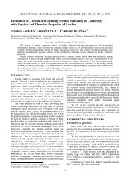
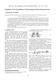
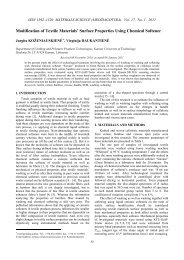
Fig. 1 Diagram <strong>of</strong> forces acting on <strong>the</strong> weapon<br />
Previously was analyzed <strong>the</strong> movement <strong>of</strong> a rifle<br />
during <strong>recoil</strong> assuming that a bolt is not moving within <strong>the</strong><br />
rifle. The investigated ma<strong>the</strong>matical model <strong>of</strong> <strong>the</strong> rifle’s<br />
planar motion is not precise since it does not evaluate <strong>the</strong><br />
impact <strong>of</strong> <strong>the</strong> gun bolt movement during a shot. In a real<br />
rifle, <strong>the</strong> <strong>recoil</strong> force, first <strong>of</strong> all, forces <strong>the</strong> bolt to move<br />
but does not impact <strong>the</strong> rifle directly as it was formerly<br />
analyzed. While moving within <strong>the</strong> rifle <strong>the</strong> bolt impacts<br />
<strong>the</strong> movement <strong>of</strong> <strong>the</strong> rifle during a shot. In order to revise<br />
<strong>the</strong> ma<strong>the</strong>matical model investigated, it is necessary to<br />
determine <strong>the</strong> forces impacting <strong>the</strong> bolt and <strong>the</strong> rifle. The<br />
diagram <strong>of</strong> forces acting on <strong>the</strong> weapon when it is fired has<br />
been drawn up (Fig. 1).<br />
km1<br />
m&x &<br />
A<br />
'<br />
AC<br />
'<br />
AD<br />
'<br />
DD<br />
'<br />
CC<br />
cm1<br />
F(<br />
t )<br />
m&y &<br />
β<br />
= r<br />
= s<br />
AB = q<br />
= z<br />
= w<br />
xd<br />
B<br />
bolt<br />
φ<br />
rifle<br />
c c<br />
x′<br />
F C<br />
C<br />
C ’<br />
k c<br />
L 1<br />
x
Differential equations <strong>of</strong> weapon’s planar motion<br />
have been written and investigated. In <strong>the</strong> diagram <strong>the</strong> centre<br />
<strong>of</strong> gravity is in <strong>the</strong> point A(x,y). Weapon’s butt rests<br />
against a rifleman’s shoulder and <strong>the</strong> weapon receiver is<br />
held with one hand.<br />
During <strong>recoil</strong>, <strong>the</strong> forces <strong>of</strong> stiffness and damping<br />
are acting in <strong>the</strong> points C and D. Distances L1, L2, L3 describe<br />
<strong>the</strong> condition <strong>of</strong> equilibrium. In point B <strong>recoil</strong> force<br />
F(t) is active. The coordinates <strong>of</strong> points, taking into account<br />
<strong>the</strong> gravity centre position, in plane xy are as follows<br />
( x+<br />
qcos(<br />
ϕ + β)<br />
, y+<br />
qsin(<br />
ϕ + β)<br />
)<br />
= ( x+<br />
rcosϕ<br />
, y+<br />
rsinϕ<br />
)<br />
= ( x−<br />
scosϕ<br />
, y−<br />
ssinϕ<br />
)<br />
( x+<br />
r cosϕ<br />
- w sinϕ<br />
, y+<br />
r sinϕ<br />
+ w cosϕ<br />
)<br />
( )⎪ ⎪⎪<br />
B =<br />
⎫<br />
'<br />
⎪<br />
C<br />
⎪<br />
'<br />
⎪<br />
D<br />
⎬<br />
C =<br />
D = x−<br />
s cosϕ<br />
+ z sinϕ<br />
, y−<br />
s sinϕ<br />
− z cosϕ<br />
⎭<br />
The forces, acting in points C and D are evaluated<br />
by equations<br />
F<br />
− c<br />
F<br />
− c<br />
F<br />
C<br />
Dx<br />
Dy<br />
− c<br />
( )<br />
( )<br />
( )<br />
( )<br />
( )<br />
( ) ⎪ ⎪⎪⎪<br />
-kC<br />
y + r sinϕ<br />
+ w cosϕ<br />
− L1<br />
− ⎫<br />
⎪<br />
y&<br />
+ r cosϕ<br />
& ϕ -w sinϕ<br />
& ϕ<br />
⎪<br />
= -k − ϕ + ϕ − − ⎪<br />
Dx x s cos z sin L3<br />
x&<br />
+ s sinϕ<br />
& ϕ + z cosϕ<br />
& ϕ<br />
⎬<br />
= -kDy<br />
y − s sinϕ<br />
- z cosϕ<br />
− L2<br />
−<br />
y&<br />
− s cosϕ<br />
& ϕ + z sinϕ<br />
& ϕ<br />
=<br />
C<br />
Dx<br />
Dy<br />
where kC, kDx, kDy are coefficients <strong>of</strong> stiffness; cC, cDx, cDy<br />
are coefficients <strong>of</strong> damping.<br />
The gun bolt is moving by <strong>the</strong> axis x′ . The equation<br />
describing <strong>the</strong> movement <strong>of</strong> <strong>the</strong> bolt will depend upon<br />
its position on this axis. The bolt’s coordinates are<br />
S( xm<br />
1, 0)<br />
. The following four cases will be analyzed in<br />
such manner.<br />
1) When x v < xm1<br />
< xd<br />
, <strong>the</strong> equation, describing<br />
<strong>the</strong> bolt movement is as follows<br />
( x&<br />
m1)<br />
+ km1xm<br />
= F(<br />
t)<br />
Fcf<br />
⎭<br />
(1)<br />
(2)<br />
m & x&<br />
+<br />
(3)<br />
1 m1<br />
+ cm1sign<br />
1<br />
Equations describing <strong>the</strong> rifle movement<br />
⎧m<br />
⎪<br />
⎪m<br />
⎪<br />
⎨m<br />
⎪<br />
⎪<br />
I<br />
⎪<br />
⎩−<br />
45<br />
where<br />
⎧ 1, when x & m1<br />
> 0<br />
⎪<br />
sign ( x & m1) = ⎨−<br />
1, when x & m1<br />
< 0<br />
⎪<br />
⎩ 0, when x & m1<br />
= 0<br />
F cf is centrifugal force, acting on <strong>the</strong> bolt by axis x′ ,<br />
2<br />
which is equal to φ& ms R ; m s is mass <strong>of</strong> <strong>the</strong> bolt; φ& is<br />
angular velocity <strong>of</strong> <strong>the</strong> bolt<br />
(4)<br />
φ2<br />
−φ<br />
t = t 1<br />
i+<br />
1 t=<br />
ti<br />
φ =<br />
dt<br />
& (5)<br />
where i = 0, 1, 2, ..., n.<br />
Radius <strong>of</strong> bolt rotation<br />
2<br />
1<br />
1 i<br />
2<br />
t t<br />
R + R<br />
t=<br />
ti+<br />
=<br />
R = (6)<br />
At point B <strong>the</strong> rifle will be impacted by force<br />
sign(<br />
x 1)<br />
k m1xm .<br />
Equations describing <strong>the</strong> rifle movement<br />
c & m1<br />
m and at point E by force 1<br />
⎧m<br />
&x<br />
& 1 m1<br />
⎪<br />
⎪m&x<br />
& =<br />
⎪<br />
⎨m&y<br />
& =<br />
⎪<br />
⎪<br />
I & ϕ&<br />
=<br />
⎪<br />
⎩+<br />
FC<br />
+ c sign(<br />
x&<br />
m1<br />
m1)<br />
+ km1x<br />
m1<br />
= F(<br />
t)<br />
+ Fcf<br />
F + c sign(<br />
x&<br />
Dx m1<br />
m1)<br />
cosϕ<br />
+ km1x<br />
m1<br />
cosϕ<br />
F + F + c sign(<br />
x&<br />
Dy C m1<br />
m1)<br />
sinϕ<br />
+ km1x<br />
m1<br />
sinϕ<br />
FDx<br />
( s sinϕ<br />
+ z cosϕ<br />
) − FDy<br />
( s cosϕ<br />
− z sinϕ<br />
)<br />
r(<br />
cosϕ<br />
− wsinϕ<br />
) − c sign(<br />
x&<br />
) w − k x w<br />
m &x<br />
&<br />
= F<br />
m1<br />
2) When x k xm<br />
< xv<br />
< 1<br />
m1<br />
( c + c ) sign(<br />
x&<br />
) + ( k + k )<br />
m1<br />
m1<br />
1 m1<br />
+ m1<br />
m2<br />
m1<br />
m1<br />
m2<br />
xm1<br />
() t + Fcf<br />
At point B <strong>the</strong> rifle will be impacted by force<br />
c c sign x&<br />
k + k x .<br />
( m1<br />
+ m2<br />
) ( m1)<br />
and at point E by force ( m1<br />
m2<br />
) m1<br />
&x<br />
& + ( c + c ) sign(<br />
x&<br />
1 m1<br />
m1<br />
m2<br />
m1<br />
) + ( k m1<br />
+ k m2<br />
) xm1<br />
= F(<br />
t)<br />
+ Fcf<br />
&x<br />
& = F + ( c + c ) sign(<br />
x&<br />
Dx m1<br />
m2<br />
m1<br />
) cosϕ<br />
+ ( k m1<br />
+ k m2<br />
) xm1<br />
cosϕ<br />
&y<br />
& = F + F + ( c + c ) sign(<br />
x&<br />
Dy C m1<br />
m2<br />
m1<br />
) sinϕ<br />
+ ( k m1<br />
+ k m2<br />
) xm1<br />
sinϕ<br />
& ϕ&<br />
= FDx<br />
( s sinϕ<br />
+ z cosϕ<br />
) − FDy<br />
( s cosϕ<br />
− z sinϕ<br />
) + FC<br />
( r cosϕ<br />
− w sinϕ<br />
) − ( cm1<br />
+ cm<br />
2 ) sign(<br />
x&<br />
m1<br />
)<br />
( k + k ) x w<br />
m1<br />
m2<br />
m1<br />
3) When <strong>the</strong> bolt strikes against <strong>the</strong> left side at<br />
point E, <strong>the</strong> force impacting <strong>the</strong> rifle will be equal to<br />
m1(<br />
1+ Rsm<br />
) x&<br />
m1<br />
Fsm<br />
= and its direction is opposite to x′ di-<br />
Δt<br />
rection.<br />
( x )<br />
Bolt velocity prior to a blow x& m1<br />
, after a blow<br />
Rsm − &m1<br />
, where Rsm is coefficient <strong>of</strong> restitution,<br />
0
point B, <strong>the</strong> force impacting <strong>the</strong> rifle will be equal to:<br />
m1(<br />
1+ Rsm<br />
) x&<br />
m1<br />
Fsm<br />
= and its direction will be coincident<br />
Δt<br />
with x′ direction.<br />
Equations describing <strong>the</strong> rifle movement<br />
⎧m&x<br />
& = FDx<br />
+ Fsm<br />
cosϕ<br />
⎪<br />
⎪m&y<br />
& = FDy<br />
+ FC<br />
+ Fsm<br />
sinϕ<br />
⎨<br />
⎪I<br />
& ϕ&<br />
= FDx<br />
⎪<br />
⎩−<br />
z sinϕ<br />
C<br />
( s sinϕ<br />
+ z cos)<br />
ϕ − FDy<br />
(<br />
) + F ( r cosϕ<br />
− w sinϕ<br />
) −<br />
s cosϕ<br />
−<br />
F<br />
sm<br />
w<br />
(11)<br />
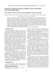
Differential equations <strong>of</strong> weapon’s plane motion<br />
are solved by using Runge-Kutta algorithm <strong>of</strong> 12 steps <strong>of</strong><br />
8(6) order [5, 6]. This algorithm automatically selects an<br />
integration step taking into account <strong>the</strong> velocity rate <strong>of</strong> <strong>the</strong><br />
process. Taking into account <strong>the</strong> fact that biomechanical<br />
characteristics <strong>of</strong> riflemen’s hands and shoulders differ, <strong>the</strong><br />
following values <strong>of</strong> <strong>the</strong> coefficients <strong>of</strong> stiffness and damping<br />
were used for calculations: kC=100 - 400 N/m; kDx=300<br />
- 1000 N/m; kDy=700 - 1700 N/m; cC=10 - 40 Ns/m; cDx=30<br />
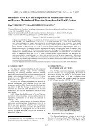
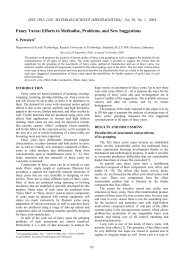
- 70 Ns/m; cDy=50 - 100 Ns/m. The samples <strong>of</strong> solutions<br />
are given in Fig. 2.<br />
x, m<br />
0.5<br />
0.45<br />
0.4<br />
0.35<br />
0 1 t, s 2<br />
1.5<br />
0 1 t, s 2<br />
1<br />
a<br />
0.1<br />
b<br />
vx, m/s<br />
0<br />
-1<br />
-2<br />
0 1<br />
c<br />
t, s 2<br />
x’, m<br />
0.1<br />
0.05<br />
0<br />
0 0.02 0.04 0.06<br />
t, s<br />
y, m<br />
1.52<br />
1.51<br />
vy, m/s<br />
-0.1<br />
0 1 t, s 2<br />
d<br />
e<br />
f<br />
Fig. 2 Imitation <strong>of</strong> a single shot: a - displacement along x<br />
axis; b - displacement along y axis; c - velocity<br />
along x axis; d - velocity along y axis; e - bolt displacement<br />
along x’ axis; f - bolt velocity along y’<br />
axis<br />
3. Constructive <strong>syn<strong>the</strong>sis</strong> <strong>of</strong> <strong>recoil</strong> <strong>imitation</strong> <strong>system</strong> <strong>of</strong><br />
<strong>the</strong> rifle<br />
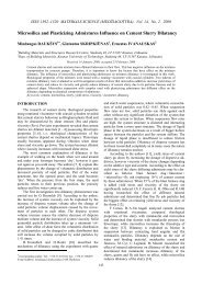
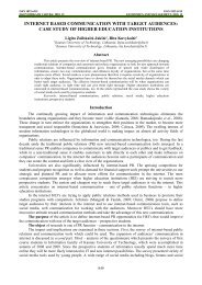
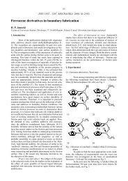
The unit scheme <strong>of</strong> <strong>the</strong> riflemen’s trainer with<br />
regulated <strong>imitation</strong> <strong>of</strong> shot <strong>recoil</strong> is depicted in <strong>the</strong> drawing.<br />
The riflemen’s training equipment (Fig. 3) consists <strong>of</strong><br />
an automatic rifle 1 that can fire single shots and shot se-<br />
0<br />
v x’, m/s<br />
10<br />
0<br />
-10<br />
0 0.02 0.04 0.06<br />
t, s<br />
46<br />
ries, a target and <strong>the</strong> <strong>system</strong> <strong>of</strong> shot <strong>imitation</strong> (not shown in<br />
<strong>the</strong> drawing). The rifle 1 has a pre-installed feeding <strong>system</strong><br />
<strong>of</strong> compressed air 2. In <strong>the</strong> chamber <strong>of</strong> <strong>the</strong> weapon’s barrel<br />
3 is installed electromagnetic valve 4, whose windings are<br />
electrically controlled by <strong>the</strong> gun trigger 5. The discharge<br />
nozzle 6 is installed at <strong>the</strong> end <strong>of</strong> <strong>the</strong> barrel chamber and its<br />
axis makes up an angle α with <strong>the</strong> axis <strong>of</strong> <strong>the</strong> barrel chamber<br />
and regulator <strong>of</strong> this angle 7.<br />
3<br />
2<br />
5<br />
Fig. 3 Scheme <strong>of</strong> <strong>recoil</strong> <strong>imitation</strong> <strong>system</strong> <strong>of</strong> <strong>the</strong> rifle:<br />
1 - rifle; 2 - feeding <strong>system</strong> <strong>of</strong> compressed air;<br />
3 - barrel chamber; 4 - electromagnetic valve;<br />
5 - trigger; 6 - discharge nozzle; 7 - position regulator<br />
<strong>of</strong> discharge nozzle<br />
The trainer functions are as follows. Upon pulling<br />
<strong>the</strong> trigger 5, <strong>the</strong> electromagnetic valve 4, selected as a 2position<br />
normally closed membranous valve for gas, receives<br />
feeding and opens <strong>the</strong> feeding <strong>system</strong> <strong>of</strong> compressed<br />
air. Then <strong>the</strong> airflow runs within <strong>the</strong> chamber <strong>of</strong><br />
<strong>the</strong> gun barrel 3 and goes out by impulses via <strong>the</strong> discharge<br />
nozzle 6 to <strong>the</strong> atmosphere. In this way, <strong>the</strong> reaction force<br />
<strong>of</strong> <strong>the</strong> outgoing airflow is used for <strong>the</strong> <strong>imitation</strong> <strong>of</strong> shot<br />
<strong>recoil</strong>. The axis <strong>of</strong> <strong>the</strong> discharge nozzle 6 makes <strong>the</strong> angle<br />
α with <strong>the</strong> axis <strong>of</strong> <strong>the</strong> barrel chamber 3, which can be regulated<br />
with <strong>the</strong> nozzle position regulator 7. The required<br />
angle α <strong>of</strong> <strong>the</strong> gun raise and <strong>the</strong> maximum value <strong>of</strong> <strong>recoil</strong><br />
force are obtained by <strong>the</strong> type and weight <strong>of</strong> <strong>the</strong> gun and<br />
axis <strong>of</strong> determination <strong>of</strong> <strong>the</strong> position angle α <strong>of</strong> <strong>the</strong> discharge<br />
nozzle and <strong>the</strong> barrel chamber <strong>of</strong> <strong>the</strong> gun. Where<br />
<strong>the</strong> trigger is pulled, <strong>the</strong> <strong>system</strong> is working in a continuous<br />
regime imitating shot series <strong>of</strong> <strong>the</strong> automatic gun. Upon<br />
changing position <strong>of</strong> <strong>the</strong> trigger within a certain period<br />
single shots <strong>of</strong> a gun are imitated.<br />
It should be stressed that <strong>the</strong> developed <strong>recoil</strong> <strong>imitation</strong><br />
<strong>system</strong> is universal by its technical – operational<br />
properties and may be used in <strong>the</strong> guns <strong>of</strong> o<strong>the</strong>r type, as<br />
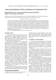
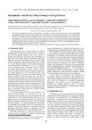
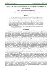
e.g. M14, M16 etc. A general view <strong>of</strong> <strong>the</strong> laser riflemen’s<br />
trainer is shown in Fig. 4.<br />
A single shots and serial shots in <strong>the</strong> created laser<br />
riflemen trainer are being simulated by means <strong>of</strong> infrared<br />
beams. Having pressed <strong>the</strong> gun trigger a laser beam or series<br />
are being radiated according <strong>the</strong> command <strong>of</strong> <strong>the</strong> control<br />
block. Simultaneously <strong>the</strong> control block activates <strong>system</strong><br />
<strong>of</strong> sound simulation and compressed air supply. There-<br />
1<br />
4 6<br />
7<br />
α<br />
α
fore every shot is accompanied by <strong>the</strong> gun <strong>recoil</strong> to <strong>the</strong><br />
rifleman’s shoulder and rifleman gets a complete image <strong>of</strong><br />
battle shooting. Having introduced <strong>the</strong> developed laser<br />
riflemen trainer <strong>the</strong> whole process <strong>of</strong> riflemen training<br />
have been fulfilled-starting from <strong>the</strong> initial instruction and<br />
finishing with <strong>the</strong> complete training.<br />
b<br />
a<br />
c<br />
Fig. 4 General view <strong>of</strong> <strong>the</strong> laser riflemen’s trainer: a - fire<br />
line; b - target view on <strong>the</strong> screen; c - information<br />
on monitor<br />
47<br />
4. Experimental investigation<br />
In <strong>the</strong> second stage <strong>the</strong> motion <strong>of</strong> <strong>the</strong> laser trainer<br />
was investigated in an experimental way by single shots<br />
and shot series. There were obtained experimental dependencies<br />
<strong>of</strong> <strong>the</strong> values describing <strong>the</strong> weapon motion (velocity<br />
and displacement) upon time. This allowed <strong>the</strong> verification<br />
<strong>of</strong> preconditions accepted when <strong>the</strong>oretically investigating<br />
<strong>the</strong> dynamics <strong>of</strong> weapon’s motion and receiving <strong>the</strong><br />
parameter values necessary for <strong>the</strong> <strong>syn<strong>the</strong>sis</strong> <strong>of</strong> <strong>recoil</strong> <strong>imitation</strong><br />
mechanism.<br />
For this purpose, an experimental stand was developed.<br />
The experimental stand consists <strong>of</strong> a weapon with<br />
fixed sensor 4506xyz <strong>of</strong> <strong>the</strong> firm Endevco. The sensor is<br />
fixed to <strong>the</strong> weapon <strong>of</strong> <strong>the</strong> laser trainer. The measurements<br />
are made in two directions <strong>of</strong> axes x and y. Bruel&Kjaer’s<br />
amplifier Nexus amplifies <strong>the</strong> signal received from <strong>the</strong> sensor.<br />
It is also used as a filter removing high frequency<br />
noises. Fur<strong>the</strong>r <strong>the</strong> signal is transferred to Bruel&Kjaer’s 4<br />
channel analyzer <strong>of</strong> vibrations 3560C. The results <strong>of</strong> measurements<br />
are visualized by using Bruel&Kjaer’s s<strong>of</strong>tware<br />
Pulse Labshop.<br />
Fig. 5 represents several charts <strong>of</strong> <strong>the</strong> created laser<br />
trainer <strong>recoil</strong> characteristics during a shot and <strong>the</strong>y show<br />
<strong>the</strong> peculiarities <strong>of</strong> trainer’s motion.<br />
x, m<br />
0.02<br />
0<br />
-0.02<br />
-0.04<br />
-0.06<br />
v x, m/s<br />
1.4<br />
0<br />
-1.2<br />
-0.2<br />
0 0.5 1 1.5t, s 2 0 0.5 1 1.5t, s 2<br />
c d<br />
Fig. 5 Imitation <strong>of</strong> a single shot with <strong>the</strong> created laser<br />
trainer: a - displacement along x axis; b - displacement<br />
along y axis; c - velocity along x axis; d - velocity<br />
along y axis<br />
4. Conclusions<br />
y, m<br />
0.02<br />
-0.02<br />
1.5 2<br />
-0.04<br />
0 0.5 1 1.5<br />
t, s<br />
2<br />
a b<br />
The laser simulator is an effective aid with excellent<br />
prospects in training personnel <strong>of</strong> <strong>the</strong> defence <strong>system</strong><br />
and sportsmen, which comprises a <strong>system</strong> for transmitting<br />
infrared rays, a video receiving <strong>system</strong> and a computer<br />
<strong>system</strong> for processing. The laser simulator for riflemen was<br />
developed and approved. In order to increase its efficiency<br />
it was supplied with mechanisms and <strong>system</strong>s simulating<br />
<strong>recoil</strong> for single shots and for series <strong>of</strong> shots as well as for<br />
sound.<br />
Forces, which are operating during a shot, were<br />
investigated both <strong>the</strong>oretically and experimentally also<br />
<strong>recoil</strong> parameters were determined. Determined data is<br />
0<br />
v y, m/s<br />
0.1<br />
0<br />
-0.1
necessary for <strong>the</strong> dynamic <strong>syn<strong>the</strong>sis</strong> <strong>of</strong> <strong>recoil</strong> simulation<br />
mechanisms.<br />
The structural <strong>syn<strong>the</strong>sis</strong> <strong>of</strong> <strong>the</strong> laser simulator for<br />
riflemen with full simulation <strong>of</strong> single shots and series <strong>of</strong><br />
shots was accomplished, which resulted in creation <strong>of</strong> a<br />
simulator that is successfully used in training riflemen for<br />
<strong>the</strong> national and foreign defence institutions. The results<br />
obtained during experimental investigation fully confirm<br />
<strong>the</strong> correctness <strong>of</strong> <strong>the</strong>oretical calculations.<br />
References<br />
1. Thales Elektronik Systeme. Sagittarius - Thales Small<br />
Arms Trainer. -Thales Training & Simulation. 2004.<br />
http://www.thalesgroup.com/all/pdf/sagittarius. pdf.<br />
2. Fats, Inc. Military - Small Arms Trainer. Fats Virtual<br />
Training Solution. 2004. http://www. fatsinc.com/ military/sat/.<br />
3. Eli Military Simulation. Recoil simulation. Eli Military<br />
Simulation. 2004. http://www.eli.ee/ index.php?<br />
sect=22.<br />
4. Kwalwasser, Y. Recoil Simulator for A Weapon. U.S.<br />
Pat. 5,857,854, 1999.<br />
5. Papakostas S. N., Tsitouras Ch. High phase-lag order<br />
Runge-Kutta and Nystrom pairs. - SIAM J. Sci. Comput.,<br />
2000, v.21, p.747-763.<br />
6. Papakostas, S.N., Tsitouras, Ch. Cheap error estimation<br />
for Runge-Kutta methods.-SIAM.-J. Sci. Comput.,<br />
1999, v.20, p.2067-2088.<br />
A. Fedaravičius, M. Ragulskis, E. Sližys<br />
GINKLO ATARANKOS IMITAVIMO SISTEMOS<br />
DINAMINĖ SINTEZĖ<br />
R e z i u m ė<br />
Straipsnyje pateiktas automatinio šautuvo AK4<br />
plokščiojo judėjimo atatrankos metu teorinis tyrimas ir<br />
ginklo atatrankos imitavimo sistemos, šaudant pavieniais<br />
šūviais ir šūvių serijomis, struktūrinė sintezė. Tirtas ginklo<br />
plokščiojo judėjimo matematinis modelis sudarytas atsižvelgiant<br />
į spynos judėjimą ginklo viduje.<br />
Nustatytos jėgos, veikiančios spyną ir ginklą. Sudarytos<br />
ginklo plokščiąjį judėjimą aprašančios diferencialinės<br />
lygtys. Sukurta atatrankos imitavimo sistema yra uni-<br />
48<br />
versali ir gali būti pritaikyta kitiems ginklams, pavyzdžiui:<br />
M14, M16 ir t. t.<br />
A. Fedaravičius, M. Ragulskis, E. Sližys<br />
DYNAMIC SYNTHESIS OF THE RECOIL IMITATION<br />
SYSTEM OF WEAPONS<br />
S u m m a r y<br />
The article presents a <strong>the</strong>oretical investigation <strong>of</strong><br />
planar motion <strong>of</strong> <strong>the</strong> automatic weapon AK4 during <strong>recoil</strong><br />
and constructive <strong>syn<strong>the</strong>sis</strong> <strong>of</strong> <strong>recoil</strong> <strong>imitation</strong> <strong>system</strong> with<br />
full simulation <strong>of</strong> single shots and series <strong>of</strong> shots <strong>of</strong> <strong>the</strong><br />
rifle. The investigated ma<strong>the</strong>matical model <strong>of</strong> planar motion<br />
<strong>of</strong> rifles was created considering movement <strong>of</strong> bolt<br />
inside <strong>the</strong> rifle.<br />
Was determined <strong>the</strong> forces impacting <strong>the</strong> bolt and<br />
<strong>the</strong> rifle. Differential equations <strong>of</strong> <strong>weapons</strong> planar motion<br />
have been written. The developed <strong>recoil</strong> <strong>imitation</strong> <strong>system</strong><br />
is universal and may be used in <strong>the</strong> guns <strong>of</strong> o<strong>the</strong>r type, as<br />
e.g. M14, M16 etc.<br />
А. Федаравичюс, М. Рагулськис, Э. Слижис<br />
ДИНАМИЧЕСКИЙ СИНТЕЗ СИСТЕМЫ<br />
ИМИТАЦИИ ОТДАЧИ ОРУЖИЯ<br />
Р е з ю м е<br />
Статья представляет теоретическое исследование<br />
плоского движения автоматического оружия<br />
AK4 во время отдачи и конструктивный синтез системы<br />
имитации отдачи при стрельбе одиночными выстрелами<br />
и стрельбе очередями. Исследованная математическая<br />
модель плоского движения винтовок была<br />
создана, рассматривая движение замка в винтовке.<br />
Определены силы, действующие на замок и<br />
винтовку, составлены дифференциальные уравнения<br />
плоского движения оружия. Созданная система имитации<br />
отдачи универсальна и может быть использована<br />
для оружия другого типа, как, например: M14, M16 и<br />
т.д.<br />
Received October 21, 2004