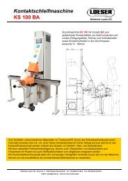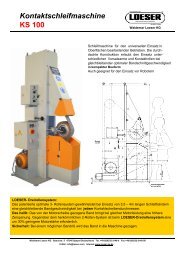
Technical data Pneumatic belt grinding machine 40320 (PDF
Technical data Pneumatic belt grinding machine 40320 (PDF
Technical data Pneumatic belt grinding machine 40320 (PDF

Create successful ePaper yourself
Turn your PDF publications into a flip-book with our unique Google optimized e-Paper software.
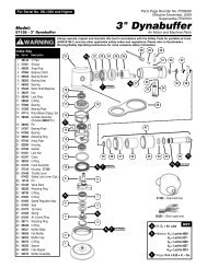
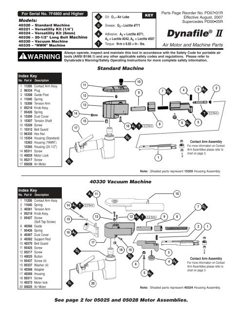
For Serial No. 7F4860 and Higher<br />
Models:<br />
<strong>40320</strong> – Standard Machine<br />
40321 – Versatility Kit (1/4")<br />
40324 – Versatility Kit (6mm)<br />
40326 – 20-1/2" Long Belt Machine<br />
40330 – Vacuum Machine<br />
3.0 N m<br />
Parts Page Reorder No. PD07 31R<br />
Effective August, 2007<br />
Supercedes PD00 05R<br />
Dynafile ® II<br />
40335 – “NWN” Machine T Torque: N m x 8.85 = In - lbs. Air Motor and Machine Parts<br />
Index Key<br />
No. Part # Description<br />
1 11206 Contact Arm Assy.<br />
2 96334 Plug<br />
3 15308 Guide Post<br />
4 11040 Spring<br />
5 15306 Tension Arm<br />
6 95218 Knob Assy.<br />
7 95426 Spring<br />
8 15309 Dust Cover<br />
9 15307 Tension Shaft<br />
10 15329 Screw<br />
11 15312 Belt Guard<br />
12 96335 Hex Nut<br />
13 15354 Housing (Standard)<br />
15363 Housing (“NWN”)<br />
15365 Housing (20-1/2")<br />
14 95311 Screw<br />
15 40029 Motor Lock<br />
16 95217 Screw<br />
17 05028 Air Motor<br />
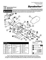
Index Key<br />
No. Part # Description<br />
1 11206 Contact Arm Assy.<br />
2 11040 Spring<br />
3 40361 Tension Arm<br />
4 95218 Knob Assy.<br />
5 95427 Screw<br />
(Self-Tap Screw)<br />
6 40366 Guide<br />
7 95426 Spring<br />
8 40367 Dust Cover<br />
9 40362 Support Rod<br />
10 40370 Belt Guard<br />
11 95425 Screw<br />
12 95217 Screw<br />
13 40025 Button<br />
14 95437 Screw (4)<br />
15 95337 Washer (4)<br />
16 40368 Adapter<br />
17 40369 Housing<br />
18 95311 Screw<br />
19 40373 Motor lock<br />
20 05025 Air Motor<br />
Always operate, inspect and maintain this tool in accordance with the Safety Code for portable air<br />
tools (ANSI B186.1) and any other applicable safety codes and regulations. Please refer to<br />
Dynabrade’s Warning/Safety Operating Instructions for more complete safety information.<br />
G 2<br />
O 1<br />
14<br />
15<br />
16<br />
O 1<br />
14<br />
A 3<br />
A 9<br />
17<br />
G 2<br />
T<br />
11<br />
12<br />
13<br />
15<br />
3.0 N m<br />
Standard Machine<br />
40330 Vacuum Machine<br />
A 3<br />
17<br />
20<br />
11<br />
13<br />
O<br />
G<br />
A<br />
Oil: O 1 = Air Lube<br />
Grease: G 2 = Loctite #771<br />
Adhesive: A 2 = Loctite #271,<br />
A 3 = Loctite #242, A 9 = Loctite #587<br />
See page 2 for 05025 and 05028 Motor Assemblies.<br />
16<br />
G 2<br />
19 18<br />
10<br />
9<br />
T<br />
G 2<br />
Contact Arm Assembly<br />
For more information on Contact<br />
Arm Assemblies please refer to<br />
chart on page 3.<br />
Note: Shaded parts represent 15355 Housing Assembly.<br />
12 A3 T 3.0 N m 9 8<br />
G 2<br />
A 3<br />
6<br />
5<br />
KEY<br />
A 2<br />
1<br />
8<br />
7<br />
3<br />
4<br />
G 2<br />
10<br />
Note: Shaded parts represent 40334 Housing Assembly.<br />
6<br />
4<br />
G 2<br />
3<br />
5<br />
7<br />
2<br />
A 3<br />
T<br />
G 2<br />
1<br />
2<br />
3.0 N m<br />
Contact Arm Assembly<br />
For more information on Contact<br />
Arm Assemblies please refer to<br />
chart on page 3.
05028 — Air Motor for Standard / “NWN” Machine<br />
05025 — Air Motor for Vacuum Machine<br />
US PAT. D-265, 172; 4,368,597; 4,411,106<br />
34 N m T<br />
A 8<br />
1 7<br />
T<br />
4<br />
Drive Wheels<br />
40375 - Standard<br />
02654 - Vacuum<br />
Index Key<br />
No. Part # Description<br />
1 Drive Wheel (See Chart)<br />
2 04085 Lock Ring<br />
(Incl. (2) 95438 O-Ring)<br />
3 04086 Exhaust Control Spacer<br />
4 04087 Lock Ring<br />
5 04078 Fabric Silencer<br />
6 04084 Exhaust Control Spacer<br />
7 04081 Nut<br />
8 01007 Bearing<br />
9 01121 Shim Pack (3/pkg.)<br />
10 01008 Bearing Plate<br />
11 01009 Pin (2)<br />
12 01010 Spacer<br />
13 01013 Cylinder<br />
14 01120 Rotor<br />
2<br />
3.5 N m<br />
A 8<br />
T<br />
3<br />
5 6<br />
34 N m<br />
Right Hand Threads<br />
05025 Motor<br />
23 24 25<br />
29<br />
T<br />
15 01011 Blade (4/pkg.)<br />
16 01014 Bearing Plate<br />
17 01015 Bearing<br />
18 01447 Motor Housing<br />
19 01437 Plug<br />
20 01548 Gasket<br />
21 01461 Lock Nut<br />
22 01558 Collar<br />
23 95523 O-Ring<br />
24 01470 Insert<br />
25 Housing (See Chart)<br />
26 95558 Retaining Ring<br />
27 01448 Throttle Lever<br />
01462 Safety Lever (optional)<br />
28 12132 Pin<br />
8 9 10 12 13<br />
17 N m<br />
30<br />
31<br />
11<br />
29 01449 Valve Stem<br />
30 95730 O-Ring<br />
31 01024 O-Ring<br />
32 01469 Speed Regulator Assy.<br />
(Includes O-Rings)<br />
33 01464 Seal<br />
34 01472 Tip Valve<br />
35 01468 Spring<br />
36 01564 Spacer<br />
37 01494 Inlet Bushing<br />
ATTENTION<br />
Versatile Air Motors detach from tools in seconds. Convert to Die Grinder by adding optional 1/4" collet (50010). Convert to Drill<br />
by adding a 1/4" chuck (53032). See page 7 for Conversion Instructions.<br />
2<br />
32<br />
27<br />
28<br />
O 1<br />
33 34 35 36 37<br />
14 11 16 17 18<br />
05027 Motor<br />
05028 Motor<br />
45 N m T A8 A 8<br />
Housing<br />
05035 - Standard<br />
05032 - Vacuum<br />
26<br />
15<br />
Left Hand Threads<br />
O<br />
A<br />
T<br />
A 8<br />
T<br />
19<br />
20<br />
21<br />
22<br />
23 N m<br />
O 1<br />
Oil: O 1 = Air Lube<br />
Adhesive: A 8 = Loctite #567<br />
KEY<br />
Torque: N m x 8.85 = In.-lbs.<br />
A 8
Dynafile<br />
Part<br />
Number<br />
Abrasive<br />
Belt Size<br />
Contact Wheel<br />
Description<br />
Comments<br />
Contact Wheel<br />
Assembly<br />
Contact Wheel<br />
Only<br />
Bearing<br />
(2) Req.<br />
Shaft<br />
11200 1/2" x 18" 5/8" Dia. x 3/8" W Rubber<br />
“Stroke-Sander” Arm;<br />
1/2" W Platen<br />
11088 (2) 11077 (2) 11052 (4) 11055 (2)<br />
® II Standard Contact Arms<br />
*11201 1/2" x 18" 5/16" Dia. x 3/8" W Steel 1/2" W Platen 11068 11067 11051 11054<br />
11202 1/4" x 18" 5/8" Dia. x 1/8" W Rubber 1/4" W Platen 11074 11073 11052 11053<br />
11203 1/2" x 18" 5/8" Dia. x 3/8" W Rubber 1/2" W Platen 11078 11077 11052 11054<br />
11204 1/4" or 1/2" x 18"<br />
1" Dia. x 3/8"<br />
W Radiused Rubber<br />
Loose Belt Application 11080 11079 11052 11054<br />
11206 5/8" or 3/4" x 18" 3/4" Dia. x 5/8" W Rubber 3/4" W Platen 11282 11281 11052 11285<br />
*11220 5/8" or 3/4" x 18" 5/16" Dia. x 5/8" W Steel Polish Turbine Blades 11352 11353 11051 11285<br />
11280 1/4" x 18"<br />
1" Dia. x 3/8"<br />
W Tapered Urethane<br />
No Platen/Offset Design 11086 11085 11052 11054<br />
11286 1/2" x 24" 5/8" Dia. x 3/8" W Rubber 1/2" W Platen 11078 11077 11052 11054<br />
11287 5/8" or 3/4" x 20-1/2" 3/4" Dia. x 5/8" W Rubber 3/4" W Platen 11282 11281 11052 11285<br />
*11300 1/2" x 18" 1/4" Dia. x 3/8" W Steel Polish Turbine Blades 11332 11333 11334 11335<br />
*11301 1/2" x 18" 5/16" Dia. x 3/8" W Steel Polish Turbine Blades 11068 11067 11051 11054<br />
11304 1/2" x 18" 5/8" Dia. x 3/8" W Rubber “Stroke-Sander” Arm-1/2" W Platen 11078 11077 11052 11054<br />
11312 1/2" x 18" 5/8" Dia. x 3/8" W Rubber H.D. Version of 11203 Arm 11078 11077 11052 11054<br />
11320 1/2" x 18" 5/8" Dia. x 3/8" W Rubber “Offset Arm” – prevent gouging. 11078 11077 11052 11054<br />
11322 1/2" x 18" 5/8" Dia. x 3/8" W Rubber<br />
Contains two 11395 Guide<br />
Wheels – Prevents Undercutting<br />
11090 11077 11052 95610<br />
11325 1/2" x 18" 5/8" Dia. x 3/8" W Rubber 1/2" W Steel Platen 11078 11077 11052 11054<br />
11326 5/8" or 3/4" x 18" 3/4" Dia. x 5/8" W Rubber H.D. Version of 11206 Arm 11282 11281 11052 11285<br />
11329 1/2" x 44" 5/8" Dia. x 3/8" W Rubber 1/2" W Platen/17" Reach 11078 11077 11052 11054<br />
*11341 1/2" x 18" 5/16" Dia. x 3/8" W Rubber Polish Turbine Blades 11342 11343 11334 11335<br />
*11350 3/4" x 34" 5/16" Dia. x 5/8" W Steel Bus Bar Arm/11" Reach 11352 11353 11051 11285<br />
11360 1/2" x 18" 5/8" Dia. x 3/8" W Rubber No Platen/Offset Design 11078 11077 11052 11054<br />
**42642 5/8" or 3/4" x 18" 3/4" Dia. x 5/8" W Rubber 3/4" W Platen 42652 11281 01187 11285<br />
**42644 1/2" x 18" 5/8" Dia. x 3/8" W Rubber “Stroke-Sander” Arm-1/2" W Platen 42653 11077 01187 11054<br />
**42646 1/4" or 1/2" x 18"<br />
Dynafile ® II Contact Arm Assemblies<br />
Contact Wheel Assembly–Includes wheel, bearing and shaft.<br />
Contact Arm<br />
1" Dia. x 3/8"<br />
W Radiused Rubber<br />
Bearing<br />
Contact Wheel<br />
Bearing<br />
No Platen/Offset Design 42654 11079 01187 11054<br />
**42650 1/2" x 18" 5/8" Dia. x 3/8" W Rubber 1/2" W Platen 42653 11077 01187 11054<br />
*Run at 45 PSIG. Not recommended for Electric Dynafile ® II. **For use with Wet Dynafile ® II. Contains sealed bearings.<br />
See page 6 for Dynafile ® II Abrasives and Accessories.<br />
3<br />
Shaft
Assembly/Disassembly for Dynafile ® II<br />
Important: A #2 Arbor Press is recommended for assembly/disassembly.<br />
Manufacturers warranty is void if tool is disassembled before warranty expires.<br />
To Disassemble:<br />
Housing Assembly: Non-Vacuum<br />
1. Unscrew 15329 Screw and remove 15312 Belt Guard Assembly, abrasive <strong>belt</strong> and contact arm assembly.<br />
2. Loosen 95311 Screw and remove air motor.<br />
3. Remove 96334 Plug.<br />
4. Remove 15308 Guide Post and 96335 Hex Nut, this will release 15306 Tension Arm and 95426 Spring. (Heating of 96335<br />
Nut may be required.)<br />
Warning: 15306 Tension Arm is spring loaded, use caution when removing 15308 Guide Post.<br />
5. Remove 15309 Dust Cover, 95217 Screw and 15307 Tension Shaft. (Heating of 95217 Screw may be required.)<br />
Housing Assembly: Vacuum<br />
1. Remove 40370 Belt Guard, abrasive <strong>belt</strong> and contact arm assembly.<br />
2. Loosen 95311 Screw and remove air motor.<br />
3. Loosen 95427 Screw and remove 40366 Guide, this will release 40361 Tension Arm and 95426 Spring.<br />
Warning: 40361 Tension Arm is spring loaded, use caution when loosening 95427 Screw.<br />
4. Remove 40367 Dust cover.<br />
5. Remove 95217 Screw and 40362 Support Rod. (Heating of 95217 Screw may be required. Remove 40025 Button<br />
before heating).<br />
Motor Assembly:<br />
1. Secure Air Motor in a padded vise using 52296 Repair Collar.<br />
Important: Do not over-tighten vise or housing could be damaged.<br />
2. Remove drive wheel by inserting a 3/16" hex key through drive wheel and into the end of the 01120 Rotor/Drive Shaft.<br />
3. Using a wrench or pliers, twist the drive wheel counterclockwise and remove.<br />
4. Use a pin wrench to remove 04087/04085 Lock Ring (twist counterclockwise). Remove exhaust control spacer and<br />
silencer (if equipped).<br />
5. Pull motor assembly from housing.<br />
6. Press 01120 Rotor/Drive Shaft from 01015 Bearing and 01014 Bearing Plate.<br />
7. Press 01015 Bearing from 01014 Bearing Plate.<br />
8. Remove 01013 Cylinder and blades.<br />
9. Secure 01120 Rotor in a padded vise and remove 04081 Rotor Nut (twist counterclockwise).<br />
10. Slip off 01010 Spacer, 01008 Bearing Plate, shims and 01007 Bearing from 01120 Rotor.<br />
Valve Stem/Body Assembly:<br />
1. Secure motor housing in padded vise using 52296 Repair Collar with air inlet bushing facing upwards.<br />
2. Unscrew 01494 Inlet Bushing from valve body and remove 01564 Air Control Ring.<br />
3. Using needle nose pliers, remove 01468 Spring and 01472 Tip Valve. Pick out 01464 Seal.<br />
4. Using a 2.5 mm dia. drift pin, tap out 12132 Pin and remove throttle lever.<br />
5. Remove 95558 Retaining Ring using retaining ring pliers.<br />
6. Push 01469 Speed Regulator from housing.<br />
7. Remove 01470 Insert Assembly and 95523 O-Ring.<br />
To Assemble:<br />
Important: Make sure parts are clean and in good condition before assembling.<br />
Valve Stem/Body Assembly:<br />
1. Install 95523 O-Ring onto 01470 Insert Assembly.<br />
2. Install 01470 Assembly into valve body housing.<br />
3. Insert 01469 Speed Regulator Assembly into valve body housing. Secure with 95558 Retaining Ring.<br />
4. Secure valve body assembly in padded vise using 52296 Repair Collar with air inlet facing upward and throttle<br />
lever accessible.<br />
5. Insert 01464 Seal into housing.<br />
6. Line up the hole in 01449 Valve Stem with the hole in the housing (looking past brass bushing). Using needle nose pliers,<br />
insert 01472 Tip Valve so that the metal pin passes through the hole in the 01449 Valve Stem.<br />
7. Install 01468 Spring (small end first) over tip valve.<br />
8. Install 01564 Air Control Ring, onto 01494 Inlet Bushing.<br />
4
Assembly/Disassembly for Dynafile ® II (continued)<br />
9. Apply small amount of #567 Loctite ® (or equivalent) to threads of 01494 Inlet Bushing and install into valve body.<br />
(Torque 23 N m/200 in. lbs.).<br />
10. Install 01448 Throttle Lever and 12132 Pin. Remove valve body assembly from vise.<br />
Motor Assembly:<br />
1. Place 01120 Rotor in a padded vise.<br />
2. Slip 01010 Spacer onto 01120 Rotor.<br />
3. Place a .002 shim into 01008 Bearing Plate as an initial spacing (Note: 01121 Shim Packs contain .001 and .002 shims)<br />
and slip 01007 Bearing into plate.<br />
4. Install 01007, 01008 Bearing/Bearing Plate onto 01120 Rotor.<br />
5. Tighten 04081 Rotor Nut onto 01120 Rotor, torque to 150 in. lbs.<br />
6. Check the clearance between rotor and bearing by using a .001 feeler gauge, clearance should be at .001 to .0015. Adjust<br />
clearance by repeating steps 1–5 with different shim if necessary.<br />
7. Once proper rotor/rate clearance is achieved, install well-lubricated 01011 Blades into 01120 Rotor. Dynabrade Air Lube P/N 95842<br />
is recommended for lubrication.<br />
8. Install 01013 Cylinder so it rests against the 01007 Bearing Plate. (Make sure that air inlet holes of cylinder are facing away<br />
from 01007 Bearing Plate).<br />
9. Press 01015 Bearing into 01014 Bearing Plate. Press these parts onto 01120 Rotor. Be sure that pin and air inlet holes in<br />
bearing plate line-up with pin slot and air holes in cylinder. Important: Fit must be snug between bearing plates and<br />
cylinder. If too tight, rotor will not turn freely. Rotor must then be lightly tapped at press fit end so it will turn freely, while still<br />
maintaining a snug fit. A loose fit will not achieve the proper preload of motor bearings.<br />
10. Install motor assembly in housing, make sure motor drops all the way into housing. Line-up air inlet holes in 01014 Bearing<br />
Plate with air inlet holes in housing.<br />
11. Install exhaust control spacer, silencer and o-rings (if equipped) into lock ring. Install lock ring (small amount #567 Loctite ® or<br />
equivalent ) onto housing and torque to 34 N m/300 in. lbs.<br />
12. Motor adjustment must now be checked. With motor still mounted in vise, pull end of 01120 Rotor and twist (10-15 lbs.<br />
force), rotor should turn freely without drag. If drag or rub is felt then increase preload or remove shim (see instructions<br />
1–6). Also push end of 01120 Rotor and twist (10-15 lbs. force), rotor should turn freely without drag. If drag or rub is felt<br />
then deload or add shim.<br />
13. Motor should now be tested for proper operation at 90 PSIG. If motor does not operate properly, make necessary<br />
adjustments (see step 12).<br />
14. Install drive wheel. (Torque to 3.5 N m/30 in. lbs.)<br />
Housing Assembly: Non-Vacuum<br />
1. Place 15307 Tension Shaft into housing.<br />
2. Apply one drop of #242 Loctite ® (or equivalent) to 95217 Screw and tighten (torque to 3 N m/28 in. lbs.). (Refer to<br />
housing diagram for proper location of 95217 Screw).<br />
3. Install 15309 Dust Cover onto 15307 Tension Shaft.<br />
4. Lubricate (#771 Loctite ® or equivalent) inside of 15307 Tension Shaft and inside larger diameter of 15306 Tension Arm.<br />
5. Install 95426 Spring into 15307 Tension Shaft and place 15306 Tension Arm over 95426 Spring.<br />
6. Place 15308 Guide Post into 15306 Tension Arm, apply one drop of #242 Loctite ® (or equivalent) to screw threads.<br />
7. Compress tension arm and secure in place with 96335 Nut. (Torque to 3.0 N m/28 in. lbs.)<br />
8. Assemble 96334 Plug to 15306 Tension Arm.<br />
9. With 40029 Motor Lock in place, install air motor assembly into housing and secure in place with lubricated (#771<br />
Loctite ® or equivalent) 95311 Screw.<br />
10. Complete assembly by installing contact arm assembly, abrasive <strong>belt</strong> and place 15312 Belt Guard Assembly over housing,<br />
tighten 15329 Screw into housing.<br />
Housing Assembly: Vacuum<br />
1. Place 40362 Tension Shaft into housing.<br />
2. Apply one drop of #242 Loctite ® (or equivalent) to 95217 Screw and tighten (torque to 3.0 N m/28 in. lbs.). (Refer to<br />
housing diagram for proper location of 95217 Screw).<br />
3. Install 40637 Dust Cover onto 40362 Support Rod.<br />
4. Lubricate (#771 Loctite ® or equivalent) inside of 40362 Tension Arm.<br />
5. Install 95426 Spring into 40362 Support Rod and place 40361 Tension Arm over 95426 Spring.<br />
6. Place 40366 Guide Post into 95427 Screw, apply one drop of #271 Loctite ® (or equivalent) to screw threads.<br />
7. Compress tension arm and secure in place with 40366 Guide/95427 Screw.<br />
8. Adjust 95427 Screw so that 40361 Tension Arm slides freely, but not to loose.<br />
9. Press 40025 Button onto 95425 Screw and apply one drop of #242 Loctite ® (or equivalent) to threads.<br />
10. Place 40365 Belt Guard over 40360 Housing, tighten 95425 Screws with 40025 Button into 40360 Housing (make sure<br />
guard does not slide around, yet loose enough to remove or install without difficulty).<br />
11. With 40029 Motor Lock in place, install air motor assembly into housing and secure in place with 95311 Screw.<br />
(continued on next page)<br />
5
Assembly/Disassembly for Dynafile ® II (continued)<br />
12. Complete assembly by installing contact arm assembly, abrasive <strong>belt</strong> and 40370 Belt Guard.<br />
Tool Assembly Complete. Please allow 30 minutes for adhesives to cure before operating tool.<br />
Note: Motor should operate at between 18,000 and 20,000 RPM at 90 PSIG (6.2 Bar). RPM should be checked with a<br />
tachometer. Before operating, we recommend that 2-3 drops of Dynabrade Air Lube P/N – 95842 (or equivalent) be placed<br />
directly into the air inlet with the throttle lever depressed.<br />
Important: The regular maintenance of any air tool will contribute to greater efficiency of tool and will prolong tool life. The failure<br />
of quality pneumatic air motors can most often be traced to an unclean air supply or the lack of lubrication. Air pressure easily<br />
forces dirt or water contained in the air supply into motor bearings causing early failure. It often scores the cylinder walls and the<br />
rotor blades resulting in limited efficiency and power. Frequent drainage of water traps in air lines is recommended. Each tool on<br />
each drop should also be equipped with a secondary air processing unit. This consists of an in-line Filter-Regulator-Lubricator. All<br />
Dynabrade air tools must be used with a Filter-Regulator-Lubricator to maintain all warranties. Our warranty obligation is<br />
contingent upon proper use of our tools and cannot apply to equipment which has been subject to misuse such as unclean air, wet<br />
air or a lack of lubrication during the use of the tool.<br />
Loctite ® is a registered trademark of the Loctite Corp.<br />
Abrasive Impregnated<br />
Non-Woven Nylon<br />
18" Long/Unit = 12 Belts<br />
Grit 1/4" W 1/2" W 5/8" W 3/4" W<br />
Super fine 90158 90159 90160 90161<br />
Very fine 90228 90248 90249 90258<br />
Medium 90229 90292 90293 90294<br />
Coarse 90296 90297 90298 90299<br />
Grit<br />
24" Long/Unit = 12 Belts<br />
1/4" W 1/2" W<br />
Super fine 90397 90398<br />
Very fine 90403 90400<br />
Medium 90433 90434<br />
Coarse 90460 90461<br />
Abrasive Belts<br />
Coated Aluminum Oxide<br />
18" Long/Unit = 200 Belts<br />
24" Long/Unit = 200 Belts<br />
Grit 1/4" W 1/2" W 5/8" W 3/4" W Grit 1/4" W 1/2" W<br />
40 90220 90240 90260 90250 40 90415 90441<br />
60 90221 90241 90261 90251 60 90417 90443<br />
80 90222 90242 90262 90252 80 90419 90445<br />
120 90223 90243 90263 90253 100 90420 90446<br />
180 90224 90244 90264 90254 120 90421 90447<br />
220 90225 90245 90265 90255 180 90423 90449<br />
320 90226 90246 90266 90256 220 90424 90451<br />
500 90227 90247 90267 90257 320 90425 90453<br />
20-1/2" Long/Unit = 200 Belts<br />
500 90426 90455<br />
Grit 1/4" W 1/2" W 5/8" W 3/4" W 34" Long/Unit = 200 Belts<br />
60 90303 90317 90341 90331 Grit 3/4" W<br />
80 90304 90318 90342 90332<br />
40 90366<br />
120 90305 90319 90343 90333<br />
60 90367<br />
34" <strong>belt</strong>s are used with optional<br />
11350 Contact Arm Assembly.<br />
80<br />
100<br />
120<br />
90368<br />
90369<br />
90370<br />
6<br />
Coated Aluminum Zirconia<br />
18" Long/Unit = 200 Belts<br />
Grit 1/4" W 1/2" W 5/8" W 3/4" W<br />
60 90166 90168 90170 90172<br />
80 90167 90169 90171 90173<br />
Grit<br />
24" Long/Unit = 200 Belts<br />
1/4" W 1/2" W<br />
60 90577 90579<br />
80 90582 90583<br />
24" Long Silicon Carbide/Unit = 200 Belts<br />
Grit 1/4" W 1/2" W<br />
60 90563 90567<br />
80 90564 90568<br />
Dynapad ® Platen Pads<br />
Soft<br />
For deburring<br />
and polishing<br />
1/8"<br />
contoured pieces.<br />
11025 – 1/2" W x 7" L x 1/8" Thk. – 5/pkg.<br />
11119 – 3/4" W x 7" L x 1/8" Thk. – 5/pkg.<br />
Hard<br />
For heavy<br />
1/8"<br />
deburring<br />
and polishing.<br />
11026 – 1/2" W x 7" L x 1/8" Thk. – 5/pkg.<br />
11109 – 3/4" W x 7" L x 1/8" Thk. – 5/pkg.<br />
Thin<br />
For aggressive <strong>grinding</strong>.<br />
1/32"<br />
11027 – 1/2" W x 7" L x 1/32" Thk. – 5/pkg.<br />
11129 – 3/4" W x 7" L x 1/32" Thk. – 5/pkg.<br />
Metal<br />
For flat <strong>grinding</strong><br />
Metal<br />
and heavy stock.<br />
removal; bolts to contact arm.<br />
11024 – 1/2" W x 3" L (for Dynafile I I I11286 Arm only)<br />
Top facing<br />
Sponge<br />
base<br />
Pressure<br />
sensitive<br />
adhesive<br />
Top facing<br />
Cork base<br />
Pressure<br />
sensitive<br />
adhesive<br />
Top facing<br />
Pressure<br />
sensitive<br />
adhesive
Important Operating, Maintenance and Safety Instructions<br />
Carefully read all instructions before operating or servicing any Dynabrade ® Abrasive Power Tool.<br />
Warning: Hand, wrist and arm injury may result from repetitive work motion and overexposure to vibration.<br />
Important: All Dynabrade air tools must be used with a Filter-Regulator-Lubricator to maintain all warranties.<br />
Operating Instructions:<br />
Warning: Eye, face, respiratory, sound and body protection must be worn while operating power tools. Failure to do so may result in serious injury or death.<br />
Follow safety procedures posted in workplace.<br />
1. With power source disconnected from tool, securely fasten abrasive/accessory on tool.<br />
2. Connect power source to tool. Be careful not to depress throttle lever in the process.<br />
3. Check tool speed with tachometer. If tool is operating at a higher speed than the RPM marked on the tool or operating improperly, the tool should be<br />
serviced to correct the cause before use.<br />
4. Always work off the return side of the abrasive <strong>belt</strong>. This will ensure superior tracking and reduce down time of tool.<br />
Abrasive Belt/Contact Arm Change Instructions:<br />
To Change Belt: To Change Contact Arm Assembly:<br />
1. Disconnect power source. 1. Disconnect power source.<br />
2. Remove cover. 2. Remove cover.<br />
3. Pull back on tension arm assembly. 3. Pull back on tension arm assembly and remove abrasive <strong>belt</strong>.<br />
4. Remove and replace abrasive <strong>belt</strong> and cover. 4. Remove 95218 Rough Adjustment Knob.<br />
5. Connect power source. 5. Remove contact arm and replace with desired arm, making sure that the.<br />
6. Adjust <strong>belt</strong> tracking by turning 95218 Rough Adjustment Knob<br />
tab on the end of the arm is facing downward.<br />
to the left or right accordingly while <strong>machine</strong> is running. 6. Replace 95218 Knob.<br />
7. Install abrasive <strong>belt</strong> and cover.<br />
8. Connect power source and adjust <strong>belt</strong> tracking by turning 95218 Knob to the left<br />
or right accordingly while <strong>machine</strong> is running.<br />
Housing Angle Adjustment:<br />
To pivot housing, loosen 95311 Screw on housing with the supplied 9/64" hex wrench (P/N – 95134). Pivot housing to desired angle and retighten 95311 Screw.<br />
Conversion of Air Motor to Die Grinder or Drill:<br />
1. Remove cover and abrasive <strong>belt</strong>.<br />
2. Loosen 95311 Screw.<br />
3. Twist and pull housing from motor. Amount of force required may vary.<br />
4. Slip 95049 – 3/16" Hex Wrench (supplied in Dynafile II Kits only) through the drive wheel and into the end of the drive shaft to prevent the drive<br />
shaft from rotating.<br />
5. Using a wrench or pliers, twist the drive wheel counterclockwise and remove.<br />
6. Hold the drive shaft with a 14 mm wrench (supplied in Dynafile II Kits only) and attach collet or drill chuck (see accessories on back page).<br />
7. Use a 19 mm wrench (supplied in Dynafile II Kits only) to loosen and tighten collet cap.<br />
Maintenance Instructions:<br />
Products offered by Dynabrade should not be converted or otherwise altered from original design without the expressed written consent from Dynabrade, Inc..<br />
1. All Dynabrade air motors should be lubricated. Dynabrade recommends one drop of air lube per minute for each 10 SCFM (example: if the tool specification<br />
state 40 SCFM, set the drip rate of your filter-lubricator at 4 drops per minute). Dynabrade Air Lube (P/N 95842: 1 pt. 473 ml. ) is recommended.<br />
2. An Air Line Filter-Regulator-Lubricator must be used with this air tool to maintain all warranties. Dynabrade recommends the following: 11405 Air Line<br />
Filter-Regulator-Lubricator — Provides accurate air pressure regulation, two-stage filtration of water contaminants and positive-drip lubrication of pneumatic<br />
components. Operates 28 CFM @ 90 PSIG has 3/8" NPT female ports.<br />
3. Frequent drainage of water traps in air lines is recommended.<br />
4. Some silencers on air tools may clog with use. Clean and replace as required.<br />
5. A Motor Tune-Up Kit (P/N 96044) is available which includes assorted parts to help maintain and repair motor.<br />
Safety Instructions:<br />
Products offered by Dynabrade should not be converted or otherwise altered<br />
from original design without expressed written consent from Dynabrade, Inc.<br />
Warning: Eye, face, respiratory, sound and body protection must be worn while operating power tools. Failure to do so may result in serious injury or<br />
death. Follow safety procedures posted in workplace.<br />
Important: User of tool is responsible for following accepted safety codes such as those published by the American National Standards Institute (ANSI).<br />
Tool RPM must never exceed abrasive/accessory RPM rating, regardless of tool capacity.<br />
Operate <strong>machine</strong> for 30 seconds before application to workpiece to determine if <strong>machine</strong> is working properly and safely before work begins.<br />
Always use proper guards. Make sure guards are in proper position, secure and in good repair.<br />
Always disconnect power supply before changing abrasive or making <strong>machine</strong> adjustments.<br />
Inspect abrasives and accessories for damage or defects prior to installation on tools.<br />
Please refer to Dynabrade’s Warning/Safety Operating Instructions Tag (Reorder No. 95903) for more complete safety information.<br />
Warning: Hand, wrist and arm injury may result from repetitive work, motion and overexposure to vibration.<br />
7
80021 Dynamount<br />
Benchmount<br />
Frees an operators hands<br />
for complete control of a<br />
workpiece.<br />
Optional 80015 Foot<br />
Switch and hose assembly<br />
provides on-off foot control<br />
of air-tool operation.<br />
50010 1/4" Collet Assembly<br />
50015 6mm Collet Assembly<br />
Optional:<br />
50039 8 mm Collet Insert<br />
Fits inside 50015 Collet<br />
50065 1/8" Collet Insert<br />
Fits inside 50010 Collet<br />
96044 Motor<br />
Tune-Up Kit<br />
Includes assorted parts<br />
to help maintain and<br />
repair motor.<br />
Machine Specifications<br />
Model Motor Motor Sound Abrasive Belt Size Maximum Air Flow Max. SFPM Weight Length Height<br />
Number hp (W) RPM Level Inch (mm) SCFM (LPM) (SMPM) Pound (kg) Inch (mm) Inch (mm)<br />
<strong>40320</strong> .5 (373) 20,000 80 dB(A) 1/4-3/4 (6-19) W x 18 (457) L 28 (793) 4,550 (1,382) 2.5 (1.1) 14-1/4 (362) 4-7/8 (124)<br />
40326 .5 (373) 20,000 80 dB(A) 1/4-3/4 (6-19) W x 20-1/2 (521) L 28 (793) 4,550 (1,382) 2.5 (1.1) 14-1/4 (362) 4-7/8 (124)<br />
40330 .5 (373) 20,000 80 dB(A) 1/4-3/4 (6-19) W x 18 (457) L 28 (793) 4,550 (1,382) 2.5 (1.1) 14-1/4 (362) 4-7/8 (124)<br />
40335 .5 (373) 20,000 80 dB(A) 1/4-3/4 (6-19) W x 18 (457) L 28 (793) 4,550 (1,382) 2.5 (1.1) 14-1/4 (362) 4-7/8 (124)<br />
Additional Specifications: Air Inlet Thread 1/4" NPT Hose I.D. Size 3/8" (10mm) Air Pressure 90 PSIG (6.2 Bars)<br />
95361<br />
Air Line<br />
95396<br />
Cuff (2)<br />
Vacuum Attachment for<br />
40330 Vacuum Model Dynafile ® II<br />
95362<br />
Rubber Connector<br />
(5) 5/pkg.<br />
Accessories<br />
52296 Repair Collar<br />
Specially designed<br />
collar for use in vise.<br />
50682<br />
Vacuum Hose<br />
(Incl. cuffs)<br />
Disposable Paper Bag<br />
50692 – 12/pkg.<br />
50693 – 24/pkg.<br />
Visit Our Web Site: www.dynabrade.com Email: Customer.Service@Dynabrade.com<br />
50697<br />
Bag<br />
95391 Tie – 25/pkg.<br />
(not shown)<br />
Secures 50697 bag<br />
to vacuum hose.<br />
Dynaswivel ®<br />
Swivels 360° at two<br />
locations which<br />
allows an air hose<br />
to drop straight to<br />
the floor, no matter<br />
how the tool is held<br />
94300 1/4" NPT<br />
95461 3/8" NPT<br />
95462 1/2" NPT<br />
53032 1/4" Drill Chuck<br />
Includes: 53052 Mated Chuck Key<br />
DYNABRADE ®<br />
DYNABRADE, INC., 8989 Sheridan Drive Clarence, NY 14031-1490 Phone: (716) 631-0100 Fax: 716-631-2073 International Fax: 716-631-2524<br />
DYNABRADE EUROPE S.àr.l., Zone Artisanale L-5485 Wormeldange—Haut, Luxembourg Telephone: 352 76 84 94 1 Fax: 352 76 84 95 1<br />
© DYNABRADE, INC., 2007 PRINTED IN USA PD07.31R_Rev.1_08/07