TD 1000 PLUS - ISA
TD 1000 PLUS - ISA
TD 1000 PLUS - ISA

Create successful ePaper yourself
Turn your PDF publications into a flip-book with our unique Google optimized e-Paper software.
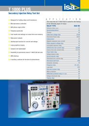
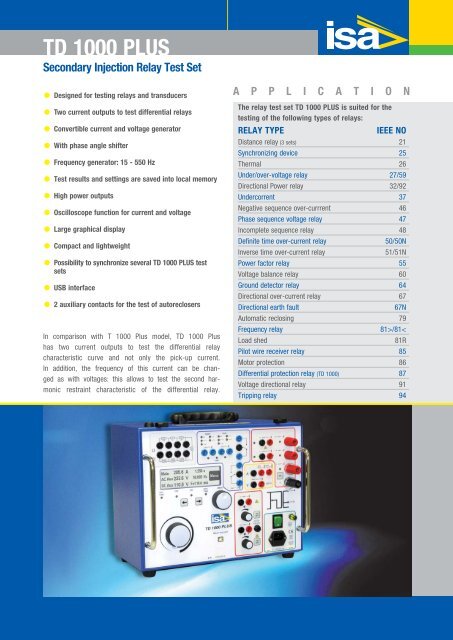
<strong>TD</strong> <strong>1000</strong> <strong>PLUS</strong><br />
Secondary Injection Relay Test Set<br />
Designed for testing relays and transducers<br />
Two current outputs to test differential relays<br />
Convertible current and voltage generator<br />
With phase angle shifter<br />
Frequency generator: 15 - 550 Hz<br />
Test results and settings are saved into local memory<br />
High power outputs<br />
Oscilloscope function for current and voltage<br />
Large graphical display<br />
Compact and lightweight<br />
Possibility to synchronize several <strong>TD</strong> <strong>1000</strong> <strong>PLUS</strong> test<br />
sets<br />
USB interface<br />
2 auxiliary contacts for the test of autoreclosers<br />
In comparison with T <strong>1000</strong> Plus model, <strong>TD</strong> <strong>1000</strong> Plus<br />
has two current outputs to test the differential relay<br />
characteristic curve and not only the pick-up current.<br />
In addition, the frequency of this current can be changed<br />
as with voltages: this allows to test the second harmonic<br />
restraint characteristic of the differential relay.<br />
A P P L I C A T I O N<br />
The relay test set <strong>TD</strong> <strong>1000</strong> <strong>PLUS</strong> is suited for the<br />
testing of the following types of relays:<br />
RELAY TYPE IEEE NO<br />
Distance relay (3 sets) 21<br />
Synchronizing device 25<br />
Thermal 26<br />
Under/over-voltage relay 27/59<br />
Directional Power relay 32/92<br />
Undercorrent 37<br />
Negative sequence over-currrent 46<br />
Phase sequence voltage relay 47<br />
Incomplete sequence relay 48<br />
Definite time over-current relay 50/50N<br />
Inverse time over-current relay 51/51N<br />
Power factor relay 55<br />
Voltage balance relay 60<br />
Ground detector relay 64<br />
Directional over-current relay 67<br />
Directional earth fault 67N<br />
Automatic reclosing 79<br />
Frequency relay 81>/81<<br />
Load shed 81R<br />
Pilot wire receiver relay 85<br />
Motor protection 86<br />
Differential protection relay (<strong>TD</strong> <strong>1000</strong>) 87<br />
Voltage directional relay 91<br />
Tripping relay 94
2<br />
<strong>TD</strong> <strong>1000</strong> <strong>PLUS</strong><br />
The instrument contains three separate generators:<br />
. Main generator, that generates either AC current, AC<br />
voltage; DC voltage;<br />
. Auxiliary AC convertible current and voltage generator, that<br />
generates an independent, phase shiftable AC voltage or<br />
current;<br />
. Auxiliary DC voltage generator, that generates the DC<br />
voltage that powers the relay under test.<br />
All outputs are adjustable and metered at the same time on the<br />
large, graphic LCD display.<br />
<strong>TD</strong> <strong>1000</strong> <strong>PLUS</strong> can operate without connection to a PC. With the<br />
multi-purpose knob and the LCD display it is possible to enter<br />
the MENU mode, that allows to set many functions, that make<br />
<strong>TD</strong> <strong>1000</strong> <strong>PLUS</strong> a very powerful testing device, with manual and<br />
semi-automatic testing capabilities, and with the possibility to<br />
transfer test results to a PC via USB interface. These results<br />
can be recorded, displayed and analysed by the powerful <strong>TD</strong>MS<br />
software, that operates with all WINDOWS versions, starting<br />
from WINDOWS 98 included.<br />
<strong>TD</strong> <strong>1000</strong> <strong>PLUS</strong> Specification<br />
Main generator<br />
The main generator has three outputs: currents, voltage AC,<br />
voltage DC. The following specifications apply to the separate<br />
usage of these outputs.<br />
AC current outputs<br />
RANGE CURRENT MAXIMUM LOAD RECOVERY<br />
A OUTPUT POWER TIME TIME<br />
AC A VA s min<br />
100 30 300 steady -<br />
100 800 60 15<br />
250 <strong>1000</strong> 1 5<br />
40 12 300 steady -<br />
40 800 60 15<br />
10 5 400 steady -<br />
10 800 60 15<br />
AC voltage outputs<br />
RANGE VOLTAGE MAXIMUM LOAD RECOVERY<br />
V OUTPUT POWER TIME TIME<br />
AC V VA s min<br />
250 250 500 steady -<br />
250 750 10 45<br />
DC voltage outputs<br />
RANGE VOLTAGE MAXIMUM LOAD RECOVERY<br />
V OUTPUT POWER TIME TIME<br />
DC V W s min<br />
300 300 300 steady -<br />
300 500 10 45<br />
Other features of main outputs<br />
. Zero crossing control. Main AC outputs are generated and<br />
stopped as the output waveform crosses zero.<br />
. High resolution adjustment control.<br />
. Overload alarm message.<br />
. Thermal protection.<br />
. Possibility to reduce the output power to one fifth for low burdens.<br />
Auxiliary AC convertible current and voltage<br />
generator<br />
The auxiliary AC convertible current and voltage generator is<br />
isolated from the main AC current and voltage.<br />
. Range selection: software driven, by the multi-function knob<br />
and LCD display.<br />
. Auxiliary voltage power: 40 VA, continuous duty, at full<br />
range; 50 VA for 1 minute.<br />
. Push-button to enable or disable the output<br />
Auxiliary AC voltage output<br />
RANGE V MAX POWER VA<br />
65 50<br />
130 50<br />
260 50<br />
. Auxiliary AC current. Power: 50 VA, continuous duty.<br />
MAX CURRENT A MAX POWER VA<br />
20 50<br />
Phase angle shifting<br />
. Possibility to phase shift the auxiliary AC voltage output<br />
with respect to the main current or voltage.<br />
. Phase angle adjustment: via the multi-function knob.<br />
. Phase angle range: from 0° to 360°.<br />
. Adjustment resolution: 1° (degree).
<strong>TD</strong> <strong>1000</strong> <strong>PLUS</strong> SECONDARY INJECTION RELAY TEST SET<br />
Frequency generator & frequency r.o.c.<br />
. Possibility to change the frequency of the auxiliary AC<br />
voltage output. Frequency generation characteristics:<br />
. Frequency range: 15 Hz to 550 Hz.<br />
. Frequency adjustment: 1 mHz.<br />
. Rate of change: 1 mHz/s to 99.99 Hz/s.<br />
Auxiliary DC voltage output<br />
. DC voltage range: 10...130 V or 20...240 V.<br />
. DC voltage power: 90 W at full range, continuous duty,<br />
with a current limit of 0.9 A @ 130 V and 0.45 A @ 240 V.<br />
. Push-button to enable or disable the output<br />
Timer<br />
The electronic digital timer has a fully automatic start and stop,<br />
both for make and break of the input, that can be either a clean<br />
(dry) contact or a contact under voltage (wet).<br />
. Metering range, can also be performed in cycles.<br />
. Possibility to test automatic reclosers.<br />
. Maximum number of reclosing commands: 99.<br />
RANGE RESOLUTION ACCURACY<br />
From 0 to 9.999 s 1 ms ± (1 ms + 0.005%)<br />
From 10.0 to 99.99 s 10 ms ± (10 ms + 0.005%)<br />
From 100.0 to 999.9 s 100 ms ± (100 ms + 0.005%)<br />
From 1.000 to 9.999 s 1 s ± (1 s + 0.005%)<br />
2 auxiliary contacts are available<br />
. Contacts range: 5 A; 250 V AC; 120 V DC.<br />
OUTPUT CURRENT AND VOLTAGE<br />
MEASUREMENTS<br />
. The following outputs are displayed at the same time on the LCD:<br />
Current measurement<br />
OUTPUT RANGE RESOLUTION ACCURACY<br />
10 A 1.999 A 1 mA ± (1% + 5 mA)<br />
19.99 A 10 mA ± (1% + 20 mA)<br />
40 A 7.999 A 4 mA ± (1% + 20 mA)<br />
79.99 A 40 mA ± (1% + 80 mA)<br />
100 A 19.99 A 10 mA ± (1% + 50 mA)<br />
199.9 A 100 mA ± (1% + 200 mA)<br />
249.9 A 100 mA ± (1% + 200 mA)<br />
Voltage measurement<br />
OUTPUT RANGE RESOLUTION ACCURACY<br />
250 V AC 19.99 V 10 mV ± (1% + 50 mV)<br />
199.9 V 100 mV ± (1% + 200 mV)<br />
299.9 V 300 mV ± (1% + 300 mV)<br />
300 V DC 19.99 V 10 mV ± (0.5% + 50 mV)<br />
199.9 V 100 mV ± (0.5% + 200 mV)<br />
399.9 V 300 mV ± (0.5% + 300 mV)<br />
65,130 V AC 19.99 V 10 mV ± (1% + 20 mV)<br />
199.9 V 100 mV ± (1% + 200 mV)<br />
260 V AC 19.99 V 10 mV ± (1% + 20 mV)<br />
199.9 V 100 mV ± (1% + 200 mV)<br />
299.9 V 300 mV ± (1% + 300 mV)<br />
20 A AC 20.00 A 10 mA ± (1% + 30 mA)<br />
130 V DC 19.99 V 10 mV ± (0.5% + 20 mV)<br />
199.9 V 100 mV ± (0.5% + 200 mV)<br />
260 V DC 19.99 V 10 mV ± (0.5% + 20 mV)<br />
199.9 V 100 mV ± (0.5% + 200 mV)<br />
299.9 V 300 mV ± (0.5% + 300 mV)<br />
Angle and frequency measurement<br />
. Via the multi-function menu knob it is possible to select the<br />
measurement of angle or frequency.<br />
. Readings, resolution and accuracy: see table.<br />
MEASUREMENT RANGE RESOLUTION ACCURACY<br />
Phase 0-360 1° 1° ± 1 Digit<br />
Frequency 15.000-499.999 1 mHz ±(0.1% + 1 mHz)<br />
Other measurements<br />
MEASUREMENT UNIT<br />
Active Power, P = I*V*cos (j) W<br />
Reactive Power, Q = I*V*sin(j) VAr<br />
Apparent Power, S = I*V VA<br />
Impedance, Z = V/I Ohm, °<br />
Active Impedance Component, R = Z* cos(j) Ohm<br />
Reactive Impedance Component, X = Z* sin(j) Ohm<br />
External inputs measurement<br />
. It is possible to meter current or voltage input.<br />
External current measurement<br />
. Two inputs: 20 mA and 10 A.<br />
3
4<br />
<strong>TD</strong> <strong>1000</strong> <strong>PLUS</strong><br />
. Range, resolution, accuracy: see table below.<br />
INPUT RANGE RESOLUTION ACCURACY<br />
20 mA 0.02 A DC 0.1 mA ± (0.5% + 0.1 mA)<br />
10 A 1.999 A AC 1 mA ± (1% + 2 mA)<br />
10 A 9.99 A AC 10 mA ± (1% + 20 mA)<br />
10 A 1.999 A DC 1 mA ± (0.5% + 2 mA)<br />
10 A 9.99 A DC 10 mA ± (0.5% + 20 mA)<br />
External voltage measurement<br />
. Maximum input voltage: 600 V, AC or DC.<br />
. Range, resolution and accuracy: see table below.<br />
RANGE RESOLUTION ACCURACY<br />
9.999 V AC 2 mV ± (1% + 10 mV)<br />
99.99 V AC 10 mV ± (1% + 20 mV)<br />
599.9 V AC 100 mV ± (1% + 200 mV)<br />
9.999 V DC 2 mV ± (0.5% + 10 mV)<br />
99.99 V DC 10 mV ± (0.5% + 20 mV)<br />
599.9 V DC 100 mV ± (0.5% + 200 mV)<br />
OTHER CHARACTERISTICS<br />
<strong>TD</strong> <strong>1000</strong> <strong>PLUS</strong> local memory<br />
. Test settings can be stored and recalled from the <strong>TD</strong> <strong>1000</strong> <strong>PLUS</strong><br />
local memory: up to 10 test settings.<br />
. Test results can be saved into a permanent local memory:<br />
up to 500 test results saved.<br />
. When the PC is connected setting can also be created and<br />
transferred into <strong>TD</strong> <strong>1000</strong> <strong>PLUS</strong> using the software <strong>TD</strong>MS.<br />
. When the PC is connected test results can be transferred to<br />
the PC via USB port using the software <strong>TD</strong>MS, for saving and<br />
printing.<br />
Resistors<br />
A set of resistors is supplied for the test of low impedance relays.<br />
Available values:<br />
RESISTANCE OHM POWER W MAX CURRENT A<br />
0,5 50 10<br />
1 50 7<br />
22 50 2.15<br />
470 50 0.33<br />
<strong>1000</strong> 50 0.22<br />
2200 50 0.15<br />
Interface<br />
. Interfaces for connection to PC: USB.<br />
Power supply<br />
. Mains supply to be clearly indicated in purchase order:<br />
230 V ± 15% 50-60 Hz or 120 V ± 15%50-60 Hz<br />
. Maximum supply current: 5 A.<br />
Standard accessories<br />
The instrument comes complete with the following items:<br />
. Set of standard test cables;<br />
. Mains cable;<br />
. USB cable;<br />
. User’s manual;<br />
. Spare fuses (no. 5), T5A.<br />
. Software <strong>TD</strong>MS with serial cable.<br />
<strong>TD</strong>MS - Relay Test Result<br />
Weight and dimension<br />
. Dimensions: 380 (w) x 300 (d) x 240 (h) mm.<br />
. Weight: 19 kg.<br />
Case<br />
Alluminium case with cover and handle.
<strong>TD</strong> <strong>1000</strong> <strong>PLUS</strong> SECONDARY INJECTION RELAY TEST SET<br />
<strong>TD</strong> <strong>1000</strong> <strong>PLUS</strong> 15 HZ<br />
With two current outputs to test differential<br />
relay and with high power at 15 Hz<br />
<strong>TD</strong> <strong>1000</strong> Plus 15 Hz is identical to <strong>TD</strong> <strong>1000</strong> Plus except<br />
for the high power and full range at 15 Hz. This allows<br />
testing old railway and generator protection relays.<br />
<strong>TD</strong> <strong>1000</strong> Plus 15 Hz does NOT have the DC battery simulator.<br />
. Power at 15 Hz: 25 VA on all ranges.<br />
. No Auxiliary DC voltage supply.<br />
. Weight: 21 kg.<br />
All other performances are the same as T <strong>1000</strong> <strong>PLUS</strong>.<br />
The request of this model must be specified at order.<br />
OPTIONS<br />
Heavy duty transport case<br />
Heavy duty black plastics transport case with handle and<br />
wheels.<br />
Connection cables<br />
The kit includes cables for any kind of connection.<br />
<strong>TD</strong> <strong>1000</strong> <strong>PLUS</strong> - Standard cable kit<br />
<strong>TD</strong> <strong>1000</strong> <strong>PLUS</strong> - Optional cable kit<br />
5
6<br />
<strong>TD</strong> <strong>1000</strong> <strong>PLUS</strong><br />
FT <strong>1000</strong> current filter<br />
This external module removes AC current distortions. It is<br />
connected in series to the relay under test, and guarantees<br />
a sinusoidal waveform also when testing current relays with<br />
reverse time characteristics, or with heavily saturating burdens,<br />
that tend to distort the current waveform.<br />
. Current input ranges: 0.5 - 2 - 10 - 50 - 100 - 200 A, on<br />
terminal bushings.<br />
. Maximum power yield: 800 VA.<br />
. Filter burden: less than 200 VA at 200 A. The burden is proportional<br />
to the range (50 VA at 50 A).<br />
. Service: 50 A continuous service; 200 A for 30 s.<br />
. Selection of the mains frequency: 50 or 60 Hz, by switch.<br />
. Dimensions: 220 x 250 x 310 mm.<br />
. Weight: 15 kg.<br />
SHA <strong>1000</strong> scanning head<br />
SHA <strong>1000</strong> is a scanning head that eases the test of energy<br />
meters. It is an universal scanning head because it can be used<br />
both with LED impulse electronic meters and Ferraris rotating<br />
disk meters; selection is performed via a switch located on the<br />
scanning head. In addition to this, a knob allows to adjust the<br />
sensitivity of the head.<br />
With rotating disk the sensor uses a green light beam<br />
that optimizes the recognition of any type of mark.<br />
With LED recognition the following specification applies:<br />
. Impulse duration: more than 60 us;<br />
. With an LED signal having a space ratio 1:2, the frequency<br />
must be less than 500 Hz.;<br />
. Light wavelength: 500 to 960 nm (red: green and blue ARE<br />
NOT detected).<br />
The option includes:<br />
- The support that allows to keep the scanning head in front of<br />
the energy meter: maximum height 175 mm;<br />
- The cable, 2 m long, from the scanning head to <strong>TD</strong> <strong>1000</strong><br />
<strong>PLUS</strong>;<br />
- The power supply transformer, for the power of 220 V AC, to<br />
supply the scanning head.<br />
- Two safety banana plugs for the connection to <strong>TD</strong> <strong>1000</strong> <strong>PLUS</strong>.<br />
Outputs transducer for low level signal relays<br />
The outputs transducer is an option that allows converting the<br />
high current and voltage outputs into low voltage signals. The<br />
option is made of three components:<br />
· The Outputs transducer, complete with the interface connector;<br />
· The connection cable from the transducer to a two BNC<br />
connectors and one RJ-45 connector, for the ABB relays<br />
REF542<strong>PLUS</strong> and REF601;<br />
· The connection cable from the transducer to one RJ-45<br />
connector, for the THYSENSOR series of THYTRONIC relays.<br />
The items can be ordered separately: the Output transducer<br />
alone, or also one cable or both.<br />
APPLICABLE STANDARDS<br />
The test set conforms to the EEC directives regarding<br />
Electromagnetic Compatibility and Low Voltage instruments.<br />
A) Electromagnetic Compatibility:<br />
Directive no. 2004/108/EC<br />
B) Low Voltage Directive:<br />
Directive n. 2006/95/EC.<br />
Applicable standards, for a class I instrument, pollution<br />
degree 2, Installation category II:<br />
. CEI EN 61010-1. In particular:<br />
. Inputs/outputs protection: IP 2X - CEI 70-1.<br />
. Operating temperature: 0 to 50°C; storage: -40°C to 70°C.<br />
. Relative humidity: 10 - 80% without condensing.
<strong>TD</strong> <strong>1000</strong> <strong>PLUS</strong> SECONDARY INJECTION RELAY TEST SET<br />
ORDERING INFORMATION<br />
CODE MODULE<br />
94093 <strong>TD</strong> <strong>1000</strong> <strong>PLUS</strong> complete with Software<br />
<strong>TD</strong>MS - 230V and standard testing cables<br />
96093 <strong>TD</strong> <strong>1000</strong> <strong>PLUS</strong> complete with Software<br />
<strong>TD</strong>MS - 120V and standard testing cables<br />
93093 <strong>TD</strong> <strong>1000</strong> <strong>PLUS</strong> 15 Hz complete with<br />
Software <strong>TD</strong>MS - 230V and standard testing<br />
cables<br />
95093 <strong>TD</strong> <strong>1000</strong> <strong>PLUS</strong> 15 Hz complete with<br />
Software <strong>TD</strong>MS - 120V and standard testing<br />
cables<br />
T <strong>1000</strong> <strong>PLUS</strong> / T <strong>1000</strong>-E <strong>PLUS</strong> / <strong>TD</strong> <strong>1000</strong> <strong>PLUS</strong> FAMILY<br />
FEATURES COMPARISON TABLE<br />
MAIN<br />
I AC<br />
MAX A<br />
MAIN<br />
V AC<br />
MAX V<br />
MAIN<br />
V DC<br />
MAX V<br />
CODE MODULE<br />
17093 Heavy Duty Transport Case<br />
18093 Set of additional test cables<br />
16093 FT <strong>1000</strong> Mains Filter Unit<br />
43102 SHA <strong>1000</strong> scanning head<br />
13093 Outputs transducer with interface connector<br />
11093 Connection cable and RJ-45 connector for<br />
ABB relays (REF542<strong>PLUS</strong> and REF601)<br />
12093 Connection cable for THYTRONIC relays<br />
(Thysensor series)<br />
AUX<br />
V AC<br />
MAX V<br />
AUX<br />
I AC<br />
AUX I/V AC<br />
POWER<br />
@ 15 Hz<br />
VA<br />
AUX<br />
V DC<br />
MAX V<br />
T <strong>1000</strong> Plus 160 250 300 250 - 10 240<br />
120 V<br />
T <strong>1000</strong> Plus 250 250 300 250 - 10 240<br />
230 V<br />
T <strong>1000</strong>- E Plus 250 500 300 500 - 10 240<br />
<strong>TD</strong> <strong>1000</strong> Plus 160 250 300 250 20 10 240<br />
120 V<br />
<strong>TD</strong> <strong>1000</strong> Plus 250 250 300 250 20 10 240<br />
230 V<br />
<strong>TD</strong> <strong>1000</strong> Plus 15 Hz 160 250 300 250 20 25 -<br />
120 V<br />
<strong>TD</strong> <strong>1000</strong> Plus 15 Hz 250 250 300 250 20 25 -<br />
230 V<br />
7
8<br />
<strong>TD</strong> <strong>1000</strong> <strong>PLUS</strong><br />
<strong>TD</strong> <strong>1000</strong> <strong>PLUS</strong><br />
<strong>TD</strong> <strong>1000</strong> <strong>PLUS</strong> 15 Hz<br />
<strong>ISA</strong> Srl<br />
Via Prati Bassi, 22<br />
21020 Taino VA - Italy<br />
-12/2012<br />
Tel +39 0331 956081<br />
Fax +39 0331 957091<br />
Web site: www.isatest.com -<strong>TD</strong><strong>1000</strong>+<br />
E-Mail: isa@isatest.com EN<br />
The document is subject to change without notice.<br />
Always refer to our technical specification for more detailed<br />
information and as formal contract document.