space tracer 4000 Operation Manual.pdf - Enlightened Lighting Ltd
space tracer 4000 Operation Manual.pdf - Enlightened Lighting Ltd
space tracer 4000 Operation Manual.pdf - Enlightened Lighting Ltd

You also want an ePaper? Increase the reach of your titles
YUMPU automatically turns print PDFs into web optimized ePapers that Google loves.
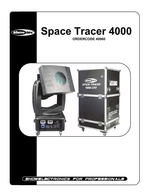
Space Tracer <strong>4000</strong><br />
ORDERCODE 40960
Congratulations!<br />
You have bought a great, innovative product from Showtec.<br />
The Showtec Space Tracer <strong>4000</strong> brings excitement to any venue. Whether you want simple plug-&-play<br />
action or a sophisticated DMX show, this product provides the effect you need.<br />
You can rely on Showtec, for more excellent lighting products.<br />
We design and manufacture professional light equipment for the entertainment industry.<br />
New products are being launched regularly. We work hard to keep you, our customer, satisfied.<br />
For more information: iwant@showtec.info<br />
You can get some of the best quality, best priced products on the market from Showtec.<br />
So next time, turn to Showtec for more great lighting equipment.<br />
Always get the best -- with Showtec !<br />
Thank you!
Showtec<br />
Showtec Space Tracer <strong>4000</strong> Product Guide<br />
Warning..…...................................................................................…………………………………………...<br />
Safety-instructions………………………………………………………………………………………….….<br />
Operating Determinations………………………………………………………………………………….<br />
Description..…..............................................................................……….………………………………..…<br />
Features and Overview ………………………………...….……………….………….…………………...<br />
Installation...............................................................................…...…………………………………….……. 6<br />
Installing the Lamp ........................................................………………………………………..………… 6<br />
Beam Angle ...............................................................................…...………………………………………..<br />
Adjusting the Beam Angle………………………………………………………………………………....<br />
Beam angle specs…………………………………………………………………………………………...<br />
Set Up and <strong>Operation</strong>.....................................................................……..………………………………….<br />
One Space Tracer ......................................................................………………………………………..<br />
Multiple Space Tracers….....................................................................………………………………...<br />
DMX-Protocol…...................................................……………………………………………………………. 10<br />
Control Panel….............……....................................……………………………………………………... 11<br />
Control Mode........................................…………………………………………………………………… 11<br />
Functions control panel...................................…………………………………………………………... 12<br />
DMX addressing...................................…………………………………………………………………..… 14<br />
Stand – alone mode...................................………………………………………………………………. 14<br />
Channel settings…………………………………………………………………………………………….. 14<br />
Maintenance...................................................................................………..………….…….…………….. 15<br />
Changing the Lamp........................................................................…………………….……………… 15<br />
Replacing the Fuse........................................................................…………………….……………….. 15<br />
Troubleshooting............................................................................………………….………………….…… 16<br />
No Light, No Movement - All Products............................................………………….……………….. 16<br />
No Response to DMX ....................................................................………………….………………….. 16<br />
Product Specifications.................................................................……………….…….…………………...<br />
18<br />
1<br />
2<br />
2<br />
3<br />
5<br />
5<br />
8<br />
8<br />
8<br />
9<br />
9<br />
9
WARNING<br />
CAUTION!<br />
Keep this device away from rain and moisture!<br />
Unplug mains lead before opening the housing!<br />
FOR YOUR OWN SAFETY, PLEASE READ THIS USER MANUAL CAREFULLY<br />
BEFORE YOUR INITIAL START-UP!<br />
SAFETY INSTRUCTIONS<br />
Every person involved with the installation, operation and maintenance of this device has to:<br />
- be qualified<br />
- follow the instructions of this manual<br />
CAUTION! Be careful with your operations.<br />
With a dangerous voltage you can suffer<br />
a dangerous electric shock when touching the wires!<br />
Before your initial start-up, please make sure that there is no damage caused by transportation. Should there<br />
be any, consult your dealer and do not use the device.<br />
To maintain perfect condition and to ensure a safe operation, it is absolutely necessary for the user to follow<br />
the safety instructions and warning notes written in this manual.<br />
Please consider that damages caused by manual modifications to the device are not subject to warranty.<br />
This device contains no user-serviceable parts. Refer servicing to qualified technicians only.<br />
IMPORTANT:<br />
The manufacturer will not accept liability for any resulting damages caused by the non-observance<br />
of this manual or any unauthorized modification to the device.<br />
Never let the power-cord come into contact with other cables! Handle the power-cord and all<br />
connections with the mains with particular caution!<br />
Never remove warning or informative labels from the unit.<br />
Never use anything to cover the ground contact.<br />
Never run the device without lamp!<br />
Never ignite the lamp if the objective-lens or any housing-cover is open, as discharge lamps may<br />
expose and emit a high ultraviolet radiation, which may cause burns.<br />
Never look directly into the light source.<br />
Never leave any cables lying around.<br />
Do not insert objects into air vents.<br />
Do not connect this device to a dimmerpack.<br />
Do not switch the device on and off in short intervals, as this would reduce the lamp’s life.<br />
If the lamp has been turned OFF, let the lamp cool down for 15 minutes, before turning the lamp ON<br />
again.<br />
Do not touch the device’s housing bare-handed during its operation (housing becomes very hot).<br />
Do not shake the device. Avoid brute force when installing or operating the device.<br />
Only use device indoor, avoid contact with water or other liquids.<br />
Only operate the fixture after having checked that the housing is firmly closed and all screws are<br />
tightly fastened.<br />
Only operate the device after having familiarized with its functions.<br />
Avoid flames and do not put close to flammable liquids or gases.<br />
2
Always replace the lamp, when it is damaged or deformed due to the heat.<br />
Always keep case closed while operating.<br />
Always allow free air <strong>space</strong> of at least 50 cm around the unit for ventilation.<br />
Always disconnect power from the mains, when device is not used, before cleaning or when<br />
replacing lamp! Only handle the power-cord by the plug. Never pull out the plug by tugging the<br />
power-cord.<br />
Make sure that the device is not exposed to extreme heat, moisture or dust.<br />
Make sure that the available voltage is not higher than stated on the rear panel.<br />
Make sure that the power-cord is never crimped or damaged. Check the device and the powercord<br />
from time to time.<br />
If the lens is obviously damaged, it has to be replaced. So that its functions are not impaired, due to<br />
cracks or deep scratches.<br />
If device is dropped or struck, disconnect mains power supply immediately. Have a qualified<br />
engineer inspect for safety before operating.<br />
If the device has been exposed to drastic temperature fluctuation (e.g. after transportation), do not<br />
switch it on immediately. The arising condensation water might damage your device. Leave the<br />
device switched off until it has reached room temperature.<br />
If your Showtec device fails to work properly, discontinue use immediately. Pack the unit securely<br />
(preferably in the original packing material), and return it to your Showtec dealer for service.<br />
For adult use only. Space Tracer must be installed out of the reach of children. Never leave the unit<br />
running unattended.<br />
For replacement use lamps and fuses of same type and rating only.<br />
Allow time to cool down, before replacing lamp.<br />
The user is responsible for correct positioning and operating of the Space Tracer. The manufacturer<br />
will not accept liability for damages caused by the misuse or incorrect installation of this device.<br />
This device falls under protection class I. Therefore it is essential to connect the yellow/green<br />
conductor to earth.<br />
During the initial start-up some smoke or smell may arise. This is a normal process and does not<br />
necessarily mean that the device is defective.<br />
Repairs, servicing and electric connection must be carried out by a qualified technician.<br />
WARRANTY: Till one year after date of purchase.<br />
OPERATING DETERMINATIONS<br />
CAUTION ! EYEDAMAGES !.<br />
Avoid looking directly into the light source.<br />
(meant especially for epileptics) !<br />
This device is not designed for permanent operation. Consistent operation breaks will ensure that the device<br />
will serve you for a long time without defects.<br />
The minimum distance between light-output and the illuminated surface must be more than 2 meters.<br />
The maximum ambient temperature ta = 40°C must never be exceeded.<br />
The relative humidity must not exceed 50 % with an ambient temperature of 40° C.<br />
If this device is operated in any other way, than the one described in this manual, the product may suffer<br />
damages and the warranty becomes void.<br />
Any other operation may lead to dangers like short-circuit, burns, electric shock, lamp explosion, crash etc.<br />
You endanger your own safety and the safety of others!<br />
Improper installation can cause serious damage to people and property !<br />
3
Connection with the mains<br />
Connect the device to the mains with the power-plug.<br />
Always pay attention, that the right color cable is connected to the right place.<br />
International EU Cable UK Cable US Cable Pin<br />
L BROWN RED YELLOW/COPPER FASE<br />
N BLUE BLACK SILVER NUL<br />
YELLOW/GREEN GREEN GREEN EARTH<br />
Make sure that the device is always connected properly to the earth!<br />
4
Description of the device<br />
Features<br />
The Showtec Space Tracer <strong>4000</strong> is an immensely powerful color changer with great effects.<br />
• DMX-control via standard DMX-controller<br />
• 12 DMX-control channels required<br />
• IP-44 Protection degree<br />
• Complete with road-proof flightcase<br />
• Stand-alone control or Master-Slave control<br />
• Lamp Osram XOB <strong>4000</strong>W Xenon included (155000 Lumen)<br />
Note: If the lamp has been turned OFF, let the lamp cool down for 15 minutes, before turning the lamp ON<br />
again.<br />
Overview<br />
1) Lens<br />
2) Yoke<br />
3) ON / OFF<br />
4) Power Supply socket<br />
5) 3-pin socket<br />
6) 5-pin socket<br />
7) Display + Setup buttons<br />
5<br />
Fig. 1
Installation<br />
Installing the Lamp<br />
The Showtec Space Tracer <strong>4000</strong> uses the XOB <strong>4000</strong>W Xenon (ordercode 80918) bulb as manufactured by all<br />
popular manufacturers. Use only the appropriate lamp for your unit.<br />
Note that, product versions that use other lamps, may be offered in the future. Check your product<br />
specification label for information.<br />
Always disconnect from electric mains power supply before changing lamps.<br />
The lamp has to be replaced when it is damaged or deformed due to the heat.<br />
Do not install lamps with a higher wattage! Lamps with a higher wattage generate temperatures the device<br />
was not designed for.<br />
Damages caused by non-observance are not subject to warranty.<br />
XBO lamps are at high internal pressure when cold (up to 35 bar) and at operating temperature (up to 80<br />
bar). Therefore, always read the instruction manual that is supplied with the lamp. The lamp may only be<br />
installed by qualified personal.<br />
Only handle lamps with their protective covers in place. Do not handle lamps without their protective covers<br />
unless approved safety glasses, facemask (with neck protector), chest protector, and gauntlets are worn.<br />
OZONE GENERATION:<br />
An electrical discharge in xenon gas generates Ozone gas (O3). Ozone is extremely toxic and will cause<br />
serious health problems if inhaled in excess of allowable limits over a prolonged period of time.<br />
Always make sure that there is enough fresh air around, when using the unit.<br />
6
Procedure :<br />
1. Loosen the 4 clamps on the housing. Gently remove the metal housing. Open the cover of the head, take<br />
out the M12 screw which can be found on the lamp. Open the cover on the back of the head, take out<br />
the fan (with connecting cable) and back board. Take the small circle board out. Use a 5mm alan key to<br />
unscrew the screw (M6) which fixes the lamp holder in place. Now you can remove the lamp holder and<br />
lamp from the light head.<br />
2. Carefully remove the old lamp.<br />
3. Read lamp instructions. Do not touch the lamp bulb.<br />
Oil on hands shortens the lamp life. (If you touch the bulb glass, wipe off the glass with a clean, lint-free<br />
towel and rubbing alcohol.). Insert the lamp.<br />
4. Now replace the lamp holder and reconnect by following the above steps in reverse order.<br />
Fig. 2<br />
7
Adjusting the Beam Angle<br />
At the back of the unit there is a small hole. Insert a screwdriver inside an turn to adjust the beam angle.<br />
Beam Angle<br />
Insert a flat screw driver in here and turn to<br />
adjust beam angle<br />
8<br />
Fig. 3
Set Up and <strong>Operation</strong><br />
Follow the directions below, as they pertain to your preferred operation mode.<br />
Before plugging the unit in, always make sure that the power supply matches the product specification<br />
voltage. Do not attempt to operate a 120V specification product on 230V power, or vice versa.<br />
After opening the packaging, unlock the TILT of the head, as shown below.<br />
LOCK (Red) locks the TILT movement of the head.<br />
UNLOCK (Green) unlocks the TILT movement of the head<br />
When transporting the device, the head must always be locked<br />
9<br />
Fig. 4<br />
Open the cover of the light head, and take out the protection sponge.<br />
When preparing for operation, please lock the 4 wheels to avoid shaking when the head is in motion.<br />
One Space Tracer<br />
1. Leave at least 1 meter on all sides for air circulation.<br />
2. Plug one end of the electric mains power cord into the IEC socket on the unit.<br />
Then plug the other end of the cord into a proper electric power supply socket.<br />
Multiple Space Tracers<br />
1. Leave at least 1 meter on all sides for air circulation.<br />
2. Use a 3-p XLR cable to connect the Space Tracers and other devices.<br />
The pins:<br />
1. Earth<br />
2. Signal -<br />
3. Signal +<br />
3. Link the units as shown in (figure 5), Connect a DMX signal cable from the first unit's DMX "out" socket to<br />
the second unit's "in" socket. Repeat this process to link the second, third, and fourth units.<br />
4. Supply electric power: Plug electric mains power cords into each unit's IEC socket, then plug the other<br />
end of the mains power cord into proper electric power supply sockets, starting with the first unit. Do not<br />
supply power before the whole system is set up and connected properly.<br />
Note: It’s necessary to insert a XLR termination plug (with 120 Ohm) in the last fixture in order to ensure<br />
proper transmission on the DMX data link.<br />
DMX-Set up<br />
Master/Slave Set up<br />
Multiple Space Tracers Set Up<br />
Note : Link all cables before connecting electric power<br />
Fig. 5
DMX Protocol<br />
Channel 1 - Horizontal movement (Pan)<br />
Push the slider up, in order to move head horizontally (PAN).<br />
Gradual head adjustment from one end of the slider to the other (0-255, 128-center).<br />
The head can be turned by 350°and stopped at any position you wish.<br />
Channel 2 - Vertical movement (Tilt)<br />
Push the slider, up in order to move head vertically (TILT).<br />
Gradual head adjustment from one end of the slider to the other (0-255, 128-center).<br />
The head can be turned by 240°and stopped at any position you wish.<br />
Channel 3 - Pan fine 16 bit<br />
Channel 4 - Tilt fine 16 bit<br />
Channel 5 –PAN/TILT Speed<br />
0-255 From Max Speed (0) to Min. Speed (255) in vector mode<br />
Channel 6 – Lamp ON OFF & Reset<br />
0-127 No Function<br />
128-139 Lamp on after 3 seconds, Reset<br />
140-229 No Function<br />
230-239 Lamp off after 3 seconds<br />
240-255 No Function<br />
Channel 7 –Cyan<br />
0-255 Gradual color change from White (0) to Full Cyan (255)<br />
Channel 8 –Magenta<br />
0-255 Gradual color change from White (0) to Full Magenta (255)<br />
Channel 9 –Yellow<br />
0-255 Gradual color change from White (0) to Full Yellow (255)<br />
Channel 10 –CMY speed adjust<br />
0-255 Gradual speed adjustment from fast (0) to slow (255)<br />
Channel 11 –Frost Filter<br />
0-255 Gradual adjustment from Beam (0) to Frost (255)<br />
Channel 12 – Dimmer / Strobe<br />
0-127 Gradual adjustment from 10% (0) to 100% (127)<br />
128-245 Strobe effect, from slow to fast (0-10 flashes/sec.)<br />
246-255 Shutter open<br />
10
Control Panel<br />
When the indicator light is on, means the Explorer is working<br />
A. LED D. [ENTER] Button<br />
B. Display E. Up Button<br />
C. [MODE] Button F. Down Button<br />
11<br />
Fig. 7<br />
Control Mode<br />
The fixtures are individually addressed on a data-link and connected to the controller.<br />
The fixtures respond to the DMX signal from the controller. (When you select the DMX address and save it, the<br />
controller will display the saved DMX address the next time.)<br />
DMX Addressing<br />
The control panel on the front side of the base allows you to assign the DMX fixture address, which is the first<br />
channel from which the Explorer will respond to the controller.<br />
Please note when you use the controller, the unit has 12 channels.<br />
When using multiple Explorers, make sure you set the DMX addresses right.<br />
Therefore, the DMX address of the first Explorer should be 1(A001); the DMX address of the second Explorer<br />
should be 1+12=13(A013); the DMX address of the third Explorer should be 13+12=25(A025), etc.<br />
Please, be sure that you don’t have any overlapping channels in order to control each Explorer correctly.<br />
If two or more Explorers are addressed similarly, they will work similarly.<br />
For address settings, please refer to the instructions under ”Addressing’ (menu )<br />
Controlling:<br />
After having addressed all Explorer fixtures, you may now start operating these via your lighting controller.<br />
Note: After switching on, the Explorer will automatically detect whether DMX 512 data is received or not. If<br />
there is no data received at the DMX-input, the “LED “ on the control panel will not flash.<br />
The problem may be:<br />
- The XLR cable from the controller is not connected with the input of the Explorer.<br />
- The controller is switched off or defective, the cable or connector is detective, or the signal wires are<br />
swapped in the input connector.<br />
Note: It’s necessary to insert a XLR termination plug (with 120 Ohm) in the last fixture in order to ensure proper<br />
transmission on the DMX data link.
Control Panel Functions<br />
12
Stand-alone Mode<br />
The fixtures on a data-link are not connected to the controller, but can execute a pre-set program.<br />
To set the program to be played, by pressing the Mode button until the display shows RUN, then select UP. If<br />
the display shows PRG then select Enter.<br />
Stand-alone operation” can be applied to a single fixture (the fixture may be set to the master/slave mode<br />
or controller mode) or to multiple fixture operating synchronously.<br />
For synchronous operation of multiple fixtures, the fixtures must all be connected on a data-link and one of<br />
them is set as a master (master mode) and the rest as slaves (slave mode). The DMX address of all the<br />
slaves are assigned to and on that particular slave address only one fixture can be connected. To the<br />
fixture as the master or slave, see “Addressing” (menu ).<br />
If the master fixture resets or runs a test (program), all slaves will execute these acts too.<br />
You can’t play or edit any program on a slave, if the master is switched on and connected to the<br />
master/slave chain.<br />
Note: Disconnect the fixtures from the DMX controller before master/slave operating, otherwise data<br />
collisions can occur and the fixtures will not work properly!<br />
It’s necessary to insert the XLR termination plug (with 120 Ohm ) into the input of the master fixture and into<br />
the output of the last slave fixture in the data-link, in order to ensure proper transmission on the data link.<br />
From the master’s control panel it is possible to control any slave in a master/slave chain.<br />
Addressing<br />
With this menu you can set the DMX address or address a fixture as a master/slave.<br />
- DMX addressing<br />
1) Press Choose, until the display shows .<br />
2) Press Enter to confirm.<br />
Then press Up / Down to select the required address , press Enter to confirm.<br />
3) Press Choose, the chosen address is shown on the display.<br />
Master / slave addressing<br />
1) Press Mode, until the display shows RUN, then select UP.<br />
2) Only one fixture can be the master. Up to the 16 slaves may be connected to the master.<br />
Note: Disconnect the fixture from the DMX controller before master/slave operating, otherwise data<br />
collisions can occur and the fixtures will not work properly!<br />
In master/slave mode, the master fixture can execute the built-in program, all the slave fixtures will work<br />
the same.<br />
3) On the Slave devices you must press Mode, until the display shows RUN. Then select UP until the<br />
display shows SLAE and press Enter.<br />
14
Maintenance<br />
The operator has to make sure that safety-relating and machine-technical installations are to be inspected<br />
by an expert after every four years in the course of an acceptance test.<br />
The operator has to make sure that safety-relating and machine-technical installations are to be inspected<br />
by a skilled person once a year.<br />
The following points have to be considered during the inspection:<br />
1. All screws used for installing the device or parts of the device have to be tightly connected and must<br />
not be corroded.<br />
2. There may not be any deformations on housings, fixations and installation spots.<br />
3. Mechanically moving parts like axles, eyes and others may not show any traces of wearing.<br />
4. The electric power supply cables must not show any damages or material fatigue.<br />
The Showtec Space Tracer <strong>4000</strong> requires almost no maintenance. However, you should keep the unit clean.<br />
Otherwise, the fixture’s light-output will be significantly reduced. Disconnect the mains power supply, and<br />
then wipe the cover with a damp cloth. Do not immerse in liquid. Wipe lens clean with glass cleaner and a<br />
soft cloth. Do not use alcohol or solvents.<br />
The cooling-fans, colour-filters, and the internal lenses should be cleaned monthly with a soft brush.<br />
Please clean internal components once a year with a light brush and vacuum cleaner.<br />
Keep connections clean. Disconnect electric power, and then wipe the DMX and audio connections with a<br />
damp cloth. Make sure connections are thoroughly dry before linking equipment or supplying electric<br />
power.<br />
Changing the Lamp<br />
1. Loosen the 4 clamps on the housing. Gently remove the metal housing. Open the cover of the head, take<br />
out the M12 screw which can be found on the lamp. Open the cover on the back of the head, take out<br />
the fan (with connecting cable) and back board. Take the small circle board out. Use a 5mm alan key to<br />
unscrew the screw (M6) which fixes the lamp holder in place. Now you can remove the lamp holder and<br />
lamp from the light head.<br />
2. Carefully remove the old lamp.<br />
3. Follow directions for installing a new lamp, page 7.<br />
Replacing a Fuse<br />
You don’t have to replace a fuse on this device. The fuse is an automatic fuse, which means in case of a<br />
power surge, short-circuit or inappropriate electrical power supply, you simply have to push the reset-button<br />
on the back, and the strobe will function as before.<br />
You may want to check why the problem occurred, so you can prevent this in the future.<br />
15
Troubleshooting<br />
No Light<br />
This troubleshooting guide is meant to help solve simple problems. If a problem occurs, carry out the steps<br />
below in sequence until a solution is found. Once the unit operates properly, do not carry out following steps.<br />
If the light effect does not operate properly, refer servicing to a technician.<br />
Response: Suspect three potential problem areas: the power supply, the lamp, the fuse.<br />
1. Power supply. Check that the unit is plugged into an appropriate power supply.<br />
2. The lamp. Replace the old lamp with a new one with the same specifications. See page 7 for replacing<br />
lamps.<br />
3. The fuse. Replace the fuse. See page 16 for replacing the fuse.<br />
No Response to DMX<br />
Response: Suspect the DMX cable or connectors, a controller malfunction, a light effect DMX card<br />
malfunction.<br />
1. Check the DMX cable: Unplug the unit; change the DMX cable; then reconnect to electrical power. Try<br />
your DMX control again.<br />
2. Determine whether the controller or light effect is at fault. Does the controller operate properly with other<br />
DMX products ? If not, take the controller in for repair. If so, take the DMX cable and the light effect to a<br />
qualified technician.<br />
See next page for more problem solving.<br />
16
Problem Probable cause(s) Remedy<br />
One or more<br />
fixtures are<br />
completely dead.<br />
Fixtures reset<br />
correctly, but all<br />
respond<br />
erratically or not<br />
at all to the<br />
controller.<br />
Fixtures reset<br />
correctly, but<br />
some respond<br />
erratically or not<br />
at all to the<br />
controller.<br />
No light<br />
Lamp cuts out<br />
intermittently.<br />
No power to the fixture ·Check that power is switched on and<br />
cables are plugged in.<br />
Primary fuse blown. ·Replace fuse.<br />
The controller is not connected. ·Connect controller.<br />
3-pin XLR Out of the controller<br />
does not match XLR Out of the first<br />
fixture on the link (i.e. signal is<br />
reversed).<br />
17<br />
·Install a phase reversing cable<br />
between the controller and the first<br />
fixture on the link.<br />
·Check data quality. If much lower<br />
than 100 percent, the problem may<br />
be a bad data link connection, poor<br />
Poor data quality<br />
quality or broken cables, missing<br />
termination plug, or a defective<br />
fixture<br />
disturbing the link.<br />
·Inspect connections and cables.<br />
Bad data link connection<br />
Correct poor connections. Repair or<br />
replace damaged cables.<br />
Data link not terminated with 120 ·Insert termination plug in output jack<br />
Ohm termination plug.<br />
of the last fixture on the link.<br />
Incorrect addressing of the fixtures. ·Check address setting.<br />
One of the fixtures is defective and<br />
disturbs data transmission on the<br />
link.<br />
3-pin XLR Out on the fixtures does<br />
not match (pins 2 and 3 reversed).<br />
The power supply settings do not<br />
match local AC voltage and<br />
frequency.<br />
·Bypass one fixture at a time until<br />
normal operation is regained: unplug<br />
both connectors and connect them<br />
directly together.<br />
·Have the defective fixture serviced<br />
by<br />
a qualified technician.<br />
·Install a phase-reversing cable<br />
between the fixtures or swap pin 2<br />
and 3 in the fixture, that behaves<br />
erratically.<br />
·Disconnect fixture. Check settings<br />
(page 7) and correct if necessary.<br />
Lamp missing or blown ·Disconnect fixture and replace lamp.<br />
·Allow fixture to cool.<br />
Fixture is too hot.<br />
·Clean fan.<br />
·Make sure air vents at control panel<br />
and front lens are not blocked.<br />
·Turn up the air conditioning.<br />
The power supply settings do not ·Disconnect fixture. Check settings<br />
match local AC voltage and (page 7) and correct if necessary.<br />
frequency.
Product Specification<br />
Model: Showtec Space Tracer <strong>4000</strong><br />
Voltage: 240V-50Hz (CE)<br />
Power: 4400W<br />
Dimensions: 700 x 704 x 1430mm (LxWxH)<br />
Flightcase Dimensions: 870 x 800 x 1650 mm (LxWxH)<br />
Weight: 105 kg<br />
Minimum working temp: -27 °C<br />
Maximum working temp : 40˚ C<br />
<strong>Operation</strong> and Programming<br />
Signal pin OUT: pin 1 earth, pin 2 (-), pin 3 (+)<br />
Set Up and Addressing: Control Panel<br />
DMX Channels: 12<br />
Signal input 3-pin XLR male<br />
Signal output 3-pin XLR female<br />
Lamp<br />
Allowed lamp models*:<br />
Osram XOB <strong>4000</strong>W Xenon (1000 hr; 155000 Lumen) (ordercode 80918)<br />
Electro-mechanical effects<br />
DMX-control via standard DMX-controller<br />
CMY Color Mix effect: 3 Colors (Cyan, Magenta, Yellow)<br />
Electronic dimmer: linear adjustment 10~100%<br />
Scan fine adjust: PAN & TILT 8bit/16bit Stand-alone<br />
PAN/TILT linear speed adjustment<br />
Frost Filter: linear adjustment 0-100%<br />
Lamp ON/OFF by DMX<br />
Master / Slave<br />
DMX-controlled<br />
<strong>Manual</strong>-zoom<br />
Pan: 350º<br />
Tilt: 240º<br />
Superheat Protection<br />
IP44 protection grade<br />
3 cooling fans in the head<br />
Strobe: 0 –10 Flashes/sec<br />
Minimum distance:<br />
Minimum distance from flammable surfaces: 0.5m<br />
Minimum distance to lighted object: 2m<br />
*: Versions for other lamps may be produced. Please check the specification label on your product.<br />
Design and product specifications are subject to change without prior notice.<br />
Website: www.Highlite.nl<br />
Email: service@highlite.nl<br />
18