
You also want an ePaper? Increase the reach of your titles
YUMPU automatically turns print PDFs into web optimized ePapers that Google loves.
Toll Free: 1.800.999.0853<br />
www.compcams.com<br />
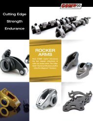
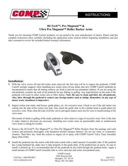
Hi-Tech, Pro Magnum &<br />
Ultra Pro Magnum Roller Rocker Arms<br />
<strong>COMP</strong> <strong>Cams</strong>®<br />
3406 Democrat Rd.<br />
Memphis, TN 38118<br />
Phone: 901.795.2400<br />
<strong>INSTRUCTIONS</strong><br />
Thank you for choosing <strong>COMP</strong> <strong>Cams</strong>® products; we are proud to be your manufacturer of choice. Please read this<br />
complete instruction sheet carefully (including the application notes section) before beginning installation and also<br />
take a moment to review the included limited warranty information.<br />
Installation:<br />
1. With the valve covers off and old rocker arms removed, the first step will be to inspect the pushrods. <strong>COMP</strong><br />
<strong>Cams</strong>® strongly suggests when installing new rocker arms (of any kind), that new <strong>COMP</strong> <strong>Cams</strong>® pushrods be<br />
incorporated to ensure that all mating surfaces are fresh to prevent any premature failures. If you are using the<br />
old pushrods, examine the ends of all pushrods for any flaking or galling. Any imperfections on the ends of the<br />
pushrods will result in either rocker arm or lifter failure. Note: Be sure to clean and blow dry all pushrods.<br />
Also, blow through the pushrod to remove any foreign matter such as sludge. Remember, in any type of<br />
motor work, cleanliness is imperative.<br />
2. Inspect rocker arm studs, stud bosses, guide plates, etc. for excessive wear. Check to see if the old rocker was<br />
cutting into the side of the rocker arm stud. Also check the guide slots in the cylinder head or guide plates for<br />
excessive wear. Wipe clean the tops of all the valves and again inspect each one for wear or mushrooming of the<br />
valve stem.<br />
Movement of metal or galling of the studs, pedestals or valve stems is a sign of excessive wear. Now is the time<br />
to make whatever decisions are necessary. Installing new rocker arms on questionable studs or mushroomed<br />
valve stems is asking for trouble.<br />
3. Remove the Hi-Tech, Pro Magnum or Ultra Pro Magnum Roller Rockers from the package and wash<br />
rockers and polylocks thoroughly with denatured alcohol (lacquer thinner). Do not use water or evaporative<br />
cleaners. Then blow dry. Soak the rockers in engine oil or spray with <strong>COMP</strong> <strong>Cams</strong>® Valve Train Assembly<br />
Spray (Part #106).<br />
4. Install the pushrods into the motor with both ends coated with a small amount of assembly lube. If the pushrod<br />
has a long hardened tip, make sure it rides properly in the guide plate. If the pushrod has an arrow, be sure to<br />
install it pointed up. It is recommended that all the pushrods be pre-oiled through the pushrod holes. Apply a<br />
small amount of <strong>COMP</strong> <strong>Cams</strong>® assembly lube to valve stem tips and rocker arm pushrod seats.<br />
Part #151<br />
Revised 3/30/12<br />
1
5. Install rocker arm on rocker stud. Pay special attention to the pushrod and rocker arm positioning. Be sure that<br />
the pushrods are seated in the lifter and rocker arm seats. Install polylocks loosely on the studs with the set<br />
screws backed off. Do not tighten the polylocks or set screws until you go through the proper sequence of lifter<br />
adjustment. Install the remainder of rockers arms in this manner.<br />
6. After carefully checking to be sure all pushrods are seated in the lifter and rocker arm, it is time for valve lash<br />
adjustment.<br />
7. Adjusting intake valves: We recommend you work with one cylinder at a time. Using the crankshaft dampener<br />
bolt in the snout of the crankshaft, turn the engine over by hand in the direction of its running rotation until the<br />
exhaust pushrod just begins to move upward to open the valve. Stop rotation. The intake lifter is now on the<br />
base circle of the cam and the intake valve is ready to be adjusted.<br />
Hydraulic Lifter <strong>Cams</strong>: Tighten the polylock until all the slack is taken out of the rocker arm and<br />
pushrod. By lightly turning the pushrod with your fingers as you tighten the polylock, you will discover<br />
or feel a point at which there will be slight resistance. At this point, you have taken all the excess slack<br />
out of the pushrod. You are now at what we refer to as zero lash. Turn the adjusting nut one-half turn<br />
more OR follow your specific lifter pre-load instructions. This will give you the ideal pre-load of the<br />
rocker arm, pushrod and lifter. Repeat this procedure for each cylinder and carefully adjust all intake<br />
valves.<br />
Solid Lifter <strong>Cams</strong>: Consult cam spec card or cam manufacturer for correct lash specifications. With the<br />
proper feeler gauge between the roller and valve stem, turn the polylock until a slight drag is felt on the<br />
feeler gauge. Hold the polylock with the wrench and then tighten the set screw using a T-handle or<br />
Allen wrench. Repeat this procedure for each cylinder and carefully adjust all intake valves.<br />
8. Adjusting exhaust valve: To adjust exhaust valves, turn the engine over until the intake pushrod moves all the<br />
way up. Rotate past maximum lift, approximately 1/2 to 2/3 of the way back down. The exhaust lifter is now on<br />
the base circle and the exhaust valve can be adjusted.<br />
Hydraulic Lifter Cam: Rotate the exhaust pushrod with your fingers and begin to tighten the exhaust<br />
polylock. When you feel the resistance on the pushrod, you are at zero lash. Rotate the polylock 1/2<br />
turn more OR follow your specific lifter pre-load instructions. Go through the exhaust valves and repeat<br />
the procedure carefully. Now all of the valves are adjusted with the proper pre-load.<br />
Solid lifter Cam: Tighten the polylock, with the proper feeler gauge between the roller tip and valve, to<br />
the point at which there is a slight drag when moving the feeler gauge. Hold the polylock with the<br />
wrench and tighten set screw. Following this procedure carefully adjust all exhaust valves.<br />
9. Before the valve covers are installed, be sure to pour engine oil on the rocker arms, making sure to coat the<br />
roller tips. This will be extra assurance that the rocker arms will have adequate lubrication until the oil travels up<br />
from the motor.<br />
Toll Free: 1.800.999.0853<br />
www.compcams.com<br />
Warning: Always Check the Following Before Operation!<br />
Old pushrods should not be used.<br />
Immediately upon startup rocker arms must have adequate oil supply.<br />
Check pushrod to cylinder head slot clearance.<br />
Check rocker arm to valve spring retainer clearance.<br />
Check for valve spring coil bind. If this occurs, the correct spring must be installed.<br />
Be sure to check for proper rocker geometry.<br />
<strong>COMP</strong> <strong>Cams</strong>®<br />
3406 Democrat Rd.<br />
Memphis, TN 38118<br />
Phone: 901.795.2400<br />
Part #151<br />
Revised 3/30/12<br />
2
Special Instructions:<br />
1. The use of old pushrods may result in pushrod or rocker arm failure. It is necessary to install new pushrods with<br />
your new Hi-Tech, Pro Magnum or Ultra Pro Magnum Roller Rocker Arms to ensure your rocker arm<br />
warranty. Pushrod ends have a mated surface to the rocker arm ball socket, much like a cam and lifter mate to each<br />
other. This is why used pushrods should not be run with the new Hi-Tech, Pro Magnum or Ultra Pro<br />
Magnum Roller Rockers.<br />
2. On racing applications with dual springs, the rocker arms should be removed and inspected after the first hour of<br />
running time.<br />
3. In some cases Hi-Tech, Pro Magnum or Ultra Pro Magnum Roller Rockers will not fit under stock valve<br />
covers due to the height of the polylocks or width of the rocker arms. Most aftermarket tall valve covers will not<br />
have any clearance problems. However, you should always check for interference.<br />
Application Notes:<br />
Toll Free: 1.800.999.0853<br />
www.compcams.com<br />
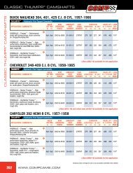
Chevrolet<br />
1965 to Present 396-454c.i.<br />
Part #1320. When installing your rockers, check your new pushrods to make sure they fit your guide plates. Chevrolet<br />
has used 3 different pushrod diameters on production big blocks - 5/16", 3/8"and 7/16". Be sure to check for valve<br />
spring coil bind, as this is a major problem area for Big Block Chevrolets.<br />
Most 1991 and newer 454-502c.i., Gen V & Gen VI engines, will need to have screw-in studs installed to run these<br />
rocker arms. <strong>COMP</strong> <strong>Cams</strong>® Part #4514-16 rocker stud kit will allow installation of screw-in studs without machining.<br />
Chevrolet<br />
1955-Present 265-400c.i., 1978-1990 V6 200-262c.i.<br />
Engines using 1.6 ratio rockers should be checked for clearance between the pushrod and pushrod slot in the cylinder<br />
head. The pushrod slot may need to be elongated. Part #4710 (the Louis Tool) can be used with a 5/16" drill bit and a<br />
hand drill to provide extra clearance. We recommend removing the cylinder head to prevent metal shavings from<br />
contaminating the engine. An alternate method is to install screw-in studs and guide plates, then drill the guide holes to<br />
1/2" diameter.<br />
Part #’s 1301, 1302, 1304 and 1305 are not self-aligning. Guide plates and heat-treated pushrods will need to be used<br />
to install these rockers on 1988 and later engines originally equipped with self-aligning rocker arms. Valve cover<br />
clearance should also be checked in these applications.<br />
Part #’s 1317 and 1318 are self-aligning. Do not use with cylinder heads that have pushrod guide slots or pushrod<br />
guide plates. Severe wear could occur. Check valve cover clearance.<br />
For high lift (.500"+) applications, longer pushrods may be required to correct rocker arm geometry. Remember, valve<br />
tip height, block deck height, cam base circle and head surface all affect pushrod length required.<br />
Part #’s 1307, 1308, 1309, and 1310 are designed with a special offset trunion to allow for use on the intakes of Trick<br />
Flow Twisted Wedge Small Block Chevrolet cylinder heads.<br />
<strong>COMP</strong> <strong>Cams</strong>®<br />
3406 Democrat Rd.<br />
Memphis, TN 38118<br />
Phone: 901.795.2400<br />
Part #151<br />
Revised 3/30/12<br />
3
Toll Free: 1.800.999.0853<br />
www.compcams.com<br />
Ford<br />
1962-1997 V8 289, 302 & 351Wc.i.<br />
Part #’s 1331 and 1332 may be used on long or short tipped valves, but must have guide plates or guide slots in the<br />
cylinder head to maintain rocker arm alignment. Most 1978 and later 302, 302H.O., and 351W engines have a cap<br />
screw (bolt) that holds the rocker arm in position. In these applications, the cylinder heads must be converted to screwin<br />
studs and guide plates when installing your rocker arms.<br />
Some 1985 and later engines are equipped with hydraulic roller cams and use special length pushrods. Be sure to use<br />
the correct pushrod.<br />
Some 1967-1977 engines come with tapered (bottleneck) studs, 3/8" bottom and 5/16" top. These will have to be<br />
removed and replaced with screw-in studs and pushrod guide plates.<br />
For high valve lift (.500"+) applications, longer pushrods may be needed to correct rocker arm geometry.<br />
Ford<br />
1970-1982 351C; 351-400Mc.i. & 1968-1997 429-460c.i.<br />
Part #1330. Screw-in studs and guide plates will be required to install Hi-Tech, Pro Magnum or Ultra Pro<br />
Magnum Roller Rockers on these engines. Check rocker arm geometry, as longer pushrods may be needed.<br />
Limited Lifetime Warranty<br />
Competition <strong>Cams</strong>, Inc. warrants this product is free from defects in material and workmanship, for the lifetime<br />
of the product. This Limited Lifetime Warranty shall cover the original purchaser.<br />
Competition <strong>Cams</strong>, Inc.’s obligation under this warranty is limited to the repair or replacement of its<br />
product. To make a warranty claim, the part must be returned to the address listed below with a valid RMA<br />
number, freight prepaid. Items covered under warranty will be returned to you freight collect.<br />
It is the responsibility of the installer to ensure that all of the components are correct before installation.<br />
We assume no liability for any errors made in tolerances, component selection, or installation.<br />
There is absolutely no warranty on the following:<br />
A) Any parts used in racing applications or subject to excessive wear;<br />
B) Any product that has been physically altered, improperly installed or maintained;<br />
C) Any product used in improper applications, abused, or not used in conjunction with the proper<br />
parts.<br />
There are no implied warranties of merchantability or fitness for a particular purpose. There are no<br />
warranties, which extend beyond the description of the face hereof. Competition <strong>Cams</strong>, Inc. will not be<br />
responsible for incidental and consequential damages, property damage or personal injury damages to the extent<br />
permitted by law. Where required by law, implied warranties or merchantability and fitness are limited to terms<br />
outlined above.<br />
This warranty gives you specific legal rights and you may also have other legal rights, which vary from state to<br />
state.<br />
<strong>COMP</strong> <strong>Cams</strong>®<br />
3406 Democrat Rd.<br />
Memphis, TN 38118<br />
Phone: 901.795.2400<br />
Part #151<br />
Revised 3/30/12<br />
4