U-GAGE T18U Ultrasonic Series - Banner Engineering
U-GAGE T18U Ultrasonic Series - Banner Engineering
U-GAGE T18U Ultrasonic Series - Banner Engineering

You also want an ePaper? Increase the reach of your titles
YUMPU automatically turns print PDFs into web optimized ePapers that Google loves.
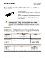
WARNING . . . Not To Be Used for Personnel Protection<br />
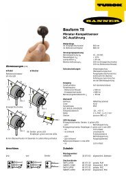
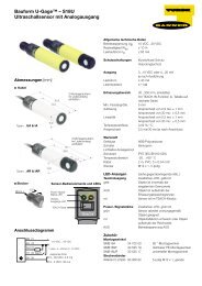
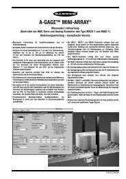
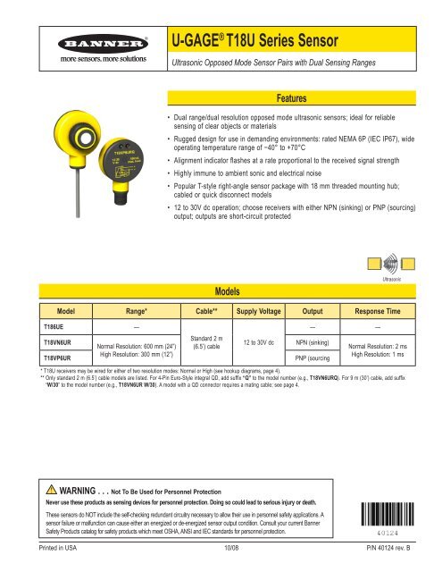
U-<strong>GAGE</strong> ® <strong>T18U</strong> <strong>Series</strong> Sensor<br />
<strong>Ultrasonic</strong> Opposed Mode Sensor Pairs with Dual Sensing Ranges<br />
Features<br />
• Dual range/dual resolution opposed mode ultrasonic sensors; ideal for reliable<br />
sensing of clear objects or materials<br />
• Rugged design for use in demanding environments: rated NEMA 6P (IEC IP67), wide<br />
operating temperature range of −40° to +70°C<br />
•<br />
•<br />
Alignment indicator flashes at a rate proportional to the received signal strength<br />
Highly immune to ambient sonic and electrical noise<br />
• Popular T-style right-angle sensor package with 18 mm threaded mounting hub;<br />
cabled or quick disconnect models<br />
• 12 to 30V dc operation; choose receivers with either NPN (sinking) or PNP (sourcing)<br />
output; outputs are short-circuit protected<br />
Models<br />
Model Range* Cable** Supply Voltage Output Response Time<br />
T186UE —<br />
T18VN6UR<br />
Normal Resolution: 600 mm (24”)<br />
Standard 2 m<br />
(6.5’) cable<br />
12 to 30V dc NPN (sinking)<br />
T18VP6UR<br />
High Resolution: 300 mm (12”)<br />
PNP (sourcing<br />
* <strong>T18U</strong> receivers may be wired for either of two resolution modes: Normal or High (see hookup diagrams, page 4).<br />
** Only standard 2 m (6.5’) cable models are listed. For 4-Pin Euro-Style integral QD, add suffix “Q” to the model number (e.g., T18VN6URQ). For 9 m (30’) cable, add suffix<br />
“W/30” to the model number (e.g., T18VN6UR W/30). A model with a QD connector requires a mating cable; see page 4.<br />
Never use these products as sensing devices for personnel protection. Doing so could lead to serious injury or death.<br />
These sensors do NOT include the self-checking redundant circuitry necessary to allow their use in personnel safety applications. A<br />
sensor failure or malfunction can cause either an energized or de-energized sensor output condition. Consult your current <strong>Banner</strong><br />
Safety Products catalog for safety products which meet OSHA, ANSI and IEC standards for personnel protection.<br />
— —<br />
<strong>Ultrasonic</strong><br />
Normal Resolution: 2 ms<br />
High Resolution: 1 ms<br />
Printed in USA 10/08 P/N 40124 rev. B
U-<strong>GAGE</strong> ® <strong>T18U</strong> <strong>Series</strong> Sensor<br />
Resolution Mode Emitter/Receiver<br />
Separation (D)<br />
Normal<br />
High<br />
2 P/N 40124 rev. B<br />
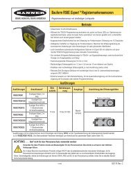
Object Detection<br />
These figures reflect the following assumptions:<br />
• Objects have square (not radiused) corners,<br />
• Sensors are optimally aligned,<br />
• Objects pass through the sensing area midway between the emitter and receiver (i.e. at D/2)*,<br />
• Operating conditions are stable, with minimal air turbulence.<br />
* In general, the minimum object width and minimum object spacing will decrease if the object<br />
(or space) to be detected is passed closer to the emitter or the receiver.<br />
Individual results may differ based on ambient operating conditions, alignment, and the<br />
geometry of the objects to be detected.<br />
Resolution Mode Emitter/Receiver<br />
Separation (D)<br />
Normal<br />
High<br />
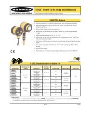
Overview<br />
U-<strong>GAGE</strong> ® <strong>T18U</strong> <strong>Series</strong> Sensors are opposed mode ultrasonic emitter/receiver pairs. They utilize an advanced built-in microprocessor to<br />
analyze the received ultrasonic signal and control an indicator LED located on the back of the receiver. The receiver LED flashes at a rate<br />
proportional to the received sonic signal strength. This indicator greatly simplifies sensor alignment and alerts personnel to marginal sensing<br />
conditions due to gradual misalignment or environmental factors. The receiver is precisely tuned to the ultrasonic emitter, making this sensor<br />
pair highly immune to both sonic and electrical ambient noise.<br />
<strong>T18U</strong> receivers may be wired for either of two resolution modes: NORMAL or HIGH. The modes are selected by the polarity of the supply<br />
voltage (see hookup diagrams, page 4). The NORMAL resolution mode offers a sensing range of 600 mm (24") and maximizes sensing<br />
energy, as is required in demanding environments. The HIGH resolution mode yields a sensing range of up to 300 mm (12") and maximizes<br />
sensing response, as is needed in high-speed counting applications.<br />
Opposed mode ultrasonics are very useful for highly reliable sensing of clear materials, which is always a challenge for photoelectric modes.<br />
<strong>T18U</strong> <strong>Series</strong> ultrasonic sensors are designed for demanding sensing environments. Housings are tough, NEMA 6P-rated PBT. Electronics are<br />
epoxy encapsulated. The acoustic face of both emitter and receiver are epoxy-reinforced for extreme durability and moisture resistance.<br />
Minimum Object Width (Typical)<br />
Velocity = 0 mm/sec<br />
(0 in/sec)<br />
Minimum Adjacent Object Spacing (Typical)<br />
Velocity = 0 mm/sec<br />
(0 in/sec)<br />
Velocity = 1270 mm/sec<br />
(50 in/sec)<br />
Velocity = 1270 mm/sec<br />
(50 in/sec)<br />
Emitter/Receiver Separation (D)<br />
Adjacent Object Spacing<br />
Emitter Receiver<br />
150 mm (6") 25.4 mm (1.0") 35.6 mm (1.40") 38.1 mm (1.50")<br />
300 mm (12") 31.8 mm (1.25") 50.8 mm (2.00") 50.8 mm (2.00")<br />
600 mm (24") 25.4 mm (1.0") 44.5 mm (1.75") 44.5 mm (1.75")<br />
150 mm (6") 15.2 mm (0.60") 19.1 mm (0.75") 20.3 mm (0.80")<br />
300 mm (12") 12.7 mm (0.50") 19.1 mm (0.75") 25.4 mm (1.0")<br />
150 mm (6") 0.8 mm (0.03") 1.0 mm (0.04") 1.3 mm (0.05")<br />
300 mm (12") 2.5 mm (0.10") 3.8 mm (0.15") 5.1 mm (0.20")<br />
600 mm (24") 8.9 mm (0.35") 10.2 mm (0.40") 12.7 mm (0.50")<br />
150 mm (6") 3.3 mm (0.13") 3.8 mm (0.15") 4.3 mm (0.17")<br />
300 mm (12") 10.2 mm (0.40") 11.4 mm (0.45") 11.4 mm (0.45")<br />
D/2<br />
Object<br />
Velocity (V)<br />
Object Width<br />
Velocity = 2540 mm/sec<br />
(100 in/sec)<br />
Velocity = 2540 mm/sec<br />
(100 in/sec)<br />
<strong>Banner</strong> <strong>Engineering</strong> Corp. • Minneapolis, MN U.S.A<br />
www.bannerengineering.com • Tel: 763.544.3164
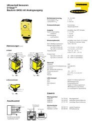
Sensing Range<br />
<strong>Ultrasonic</strong> Frequency 230 KHz<br />
Minimum Spacing<br />
(adjacent pairs)<br />
<strong>Banner</strong> <strong>Engineering</strong> Corp. • Minneapolis, MN U.S.A<br />
www.bannerengineering.com • Tel: 763.544.3164<br />
Normal Resolution: 600 mm (24")<br />
High Resolution: 300 mm (12")<br />
Supply Voltage 12 to 30V dc (10% max. ripple)<br />
Specifications<br />
U-<strong>GAGE</strong> ® <strong>T18U</strong> <strong>Series</strong> Sensor<br />
50 mm for emitter-to-receiver separations of up to 150 mm. Add 10 mm of adjacent pair spacing for every 100 mm<br />
of emitter-to-receiver spacing beyond 150 mm.<br />
Supply Current 50 mA (emitters); 35 mA (receivers), exclusive of output load<br />
Receiver Output Configuration NPN (sinking) or PNP (sourcing), depending on model; Normally Open (NO) and Normally Closed (NC)<br />
(complementary)<br />
Output Rating 150 mA max. (each output) at 25°C, derated to 100 mA at 70°C (derate ≈ 1 mA per °C).<br />
Both outputs may be used simultaneously.<br />
ON-state saturation voltage: < 1.5V at 10 mA; < 2.0V at 150 mA<br />
OFF-state leakage current: < 1 microamp at 30V dc<br />
Output Protection Circuitry Protected against overload and short circuit conditions. No false pulse upon receiver power-up.<br />
Delay at Power-up 100 milliseconds<br />
Output Response Time Normal Resolution Mode: 2 milliseconds ON and OFF<br />
High Resolution Mode: 1 millisecond ON and OFF<br />
Rep Rate Normal Resolution Mode: 125 Hz max.<br />
High Resolution Mode: 200 Hz max.<br />
Mechanical Sensing<br />
Repeatability at 300 mm (12")<br />
Range<br />
Beam Angle (-3dB full angle) 15 ± 2°<br />
Normal Resolution Mode: < 2 mm (< 0.08")<br />
High Resolution Mode: < 1 mm (< 0.04")<br />
Indicators Emitters have a Green LED for Power ON.<br />
Receivers have one Green Power LED and one Yellow Signal LED.<br />
Green Power LED: ON indicates power on<br />
Flashing indicates output overload<br />
Yellow Signal LED: sonic signal received (flash rate is proportional to received signal strength; flash is from full to<br />
half intensity)<br />
Construction Patented T-style yellow PBT housing with black PBT back cover. Transducer housing is threaded M18 x 1. Mating<br />
jam nut is supplied for mounting. Acoustic face is epoxy reinforced. Circuitry is epoxy encapsulated.<br />
Connections Emitter: 2 m (6.5') attached PVC-covered 2-wire cable or 4-pin Euro-Style quick disconnect fitting<br />
Receiver: 2 m (6.5') attached PVC-covered 4-wire cable or 4-pin Euro-Style quick disconnect fitting<br />
9 m (30') cables available by request. A model with a QD connector requires a mating cable; see page 4.<br />
Environmental Rating NEMA 6P, IEC IP67.<br />
Operating Conditions Temperature: -40° to +70°C (-40° to +158° F)<br />
Vibration and<br />
Mechanical Shock<br />
Certifications<br />
All models meet Mil. Std. 202F requirements method 201A (vibration: 10 to 60 Hz max. double amplitude 0.06",<br />
max. acceleration 10G) and method 213B conditions H & I (Shock: 75G with unit operation: 100G for non-operation)<br />
Also meets IEC 947-5-2; 30G, 11 ms duration, half sine wave.<br />
US<br />
P/N 40124 rev. B 3
U-<strong>GAGE</strong> ® <strong>T18U</strong> <strong>Series</strong> Sensor<br />
P/N 40124 rev. B<br />
30 [1.18"]<br />
Quick-Disconnect Cables<br />
Style Model Length Dimensions Pinout<br />
4-Pin Euro Straight<br />
4-Pin Euro Right-Angle<br />
MQDC-406<br />
MQDC-415<br />
MQDC-430<br />
MQDC-406RA<br />
MQDC-415RA<br />
MQDC-430RA<br />
2 m (6.5’)<br />
5 m (15’)<br />
9 m (30’)<br />
2 m (6.5’)<br />
5 m (15’)<br />
9 m (30’)<br />
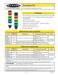
Hookups<br />
Emitter* NPN (Normal Resolution)<br />
PNP (Normal Resolution)<br />
1<br />
3<br />
12-30V dc<br />
* Emitter also functional with reverse polarity<br />
51.5<br />
[2.03"]<br />
Key<br />
1 = Brown<br />
2 = White<br />
3 = Blue<br />
4 = Black<br />
51.5<br />
[2.03"]<br />
+<br />
–<br />
4-Pin Euro<br />
1 = Brown<br />
2 = White †<br />
3 = Blue<br />
4 = Black †<br />
† Not Used<br />
62.6<br />
[2.47"]<br />
3<br />
1<br />
4<br />
2<br />
1<br />
3<br />
4<br />
2<br />
Dimensions<br />
–<br />
12-30V dc<br />
+<br />
WARRANTY: <strong>Banner</strong> <strong>Engineering</strong> Corp. warrants its products to be free from defects for one year. <strong>Banner</strong> <strong>Engineering</strong><br />
Corp. will repair or replace, free of charge, any product of its manufacture found to be defective at the time it is returned<br />
to the factory during the warranty period. This warranty does not cover damage or liability for the improper application of<br />
<strong>Banner</strong> products. This warranty is in lieu of any other warranty either expressed or implied.<br />
<strong>Banner</strong> <strong>Engineering</strong> Corp., 9714 Tenth Ave. No., Minneapolis, MN USA 55441 • Phone: 763.544.3164 • www.bannerengineering.com • Email: sensors@bannerengineering.com<br />
Load<br />
Load<br />
NPN (High Resolution)<br />
62.6<br />
[2.47"]<br />
M18 x 1<br />
Thread<br />
Load<br />
Load<br />
M18 x 1<br />
Thread<br />
30 [1.18"]<br />
–<br />
12-30V dc<br />
+<br />
44 mm<br />
max.<br />
M12 x 1<br />
38 mm<br />
max.<br />
ø 15 mm<br />
Euro Straight<br />
Euro RA<br />
M12 x 1<br />
15 [0.59"]<br />
ø 15 mm<br />
M12 x 1<br />
38 mm<br />
max.<br />
4-Pin<br />
1 = Brown<br />
2 = White<br />
3 = Blue<br />
4 = Black<br />
4-Pin<br />
1 = Brown<br />
2 = White<br />
3 = Blue<br />
4 = Black<br />
M12 x 1<br />
15 [0.59"]<br />
1<br />
3<br />
4<br />
2<br />
3<br />
1<br />
4<br />
2<br />
1<br />
4<br />
Load<br />
Load<br />
PNP (High Resolution)<br />
Load<br />
Load<br />
Green LED Power Indicator<br />
Female<br />
1 = Brown<br />
2 = White<br />
3 = Blue<br />
4 = Black<br />
+<br />
12-30V dc<br />
–<br />
+<br />
12-30V dc<br />
–<br />
Yellow LED Signal Strength Indicator<br />
(Receiver Only)<br />
Green LED Power Indicator<br />
Yellow LED Signal Strength Indicator<br />
(Receiver Only)<br />
2<br />
3<br />
4-Pin<br />
1 = Brown<br />
2 = White<br />
3 = Blue<br />
4 = Black<br />
4-Pin<br />
1 = Brown<br />
2 = White<br />
3 = Blue<br />
4 = Black