WORLD-BEAM QS18U Ultrasonic Sensors - Banner Engineering
WORLD-BEAM QS18U Ultrasonic Sensors - Banner Engineering
WORLD-BEAM QS18U Ultrasonic Sensors - Banner Engineering

Create successful ePaper yourself
Turn your PDF publications into a flip-book with our unique Google optimized e-Paper software.
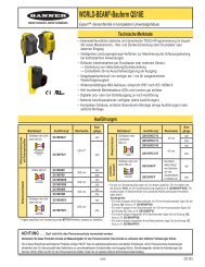
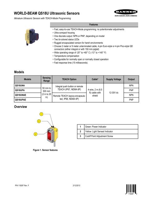
<strong>WORLD</strong>-<strong>BEAM</strong> <strong>QS18U</strong> <strong>Ultrasonic</strong> <strong>Sensors</strong><br />
Miniature <strong>Ultrasonic</strong> <strong>Sensors</strong> with TEACH-Mode Programming<br />
Models<br />
Models<br />
Sensing<br />
Range<br />
Features<br />
• Fast, easy-to-use TEACH-Mode programming; no potentiometer adjustments<br />
• Ultra-compact housing<br />
• One discrete output: NPN or PNP, depending on model<br />
• Two bi-colored status LEDs<br />
• Rugged encapsulated version for harsh environments<br />
• Choose 2 meter or 9 meter unterminated cable, 4-pin Euro-style or 4-pin Pico-style QD<br />
connectors (either integral or with 150 mm pigtail)<br />
• Wide operating range of -20° to +60° C (-13° to +140° F)<br />
• Temperature compensation<br />
• Configurable for normally open or normally closed operation<br />
• Fast response time (15 milliseconds)<br />
TEACH Option Cable* Supply Voltage Output<br />
<strong>QS18U</strong>NA<br />
Integral push button or remote<br />
NPN<br />
50 mm to<br />
<strong>QS18U</strong>PA TEACH (IP67, NEMA 6P) 4-wire, 2 m (6.5<br />
500 mm<br />
PNP<br />
ft) cable with 12-30V dc<br />
<strong>QS18U</strong>NAE (2 in to 20<br />
shield<br />
in)<br />
Remote TEACH (epoxy-encapsula-<br />
NPN<br />
<strong>QS18U</strong>PAE ted, IP68, NEMA 6P)<br />
PNP<br />
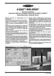
Overview<br />
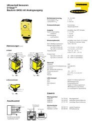
Figure 1. Sensor features<br />
P/N 119287 Rev. F 2/12/2013<br />
1 Green: Power Indicator<br />
2 Yellow: Light Sensed Indicator<br />
3 Cutoff Point Adjustment Screw<br />
0 119287 2
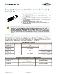
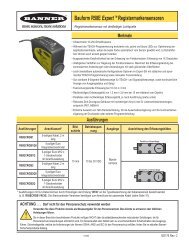
Sensor Installation<br />
Figure 2. Required Orientation of Object to Sensor<br />
Principles of Operation<br />
<strong>Ultrasonic</strong> sensors emit one or multiple pulses of ultrasonic energy, which travel through the air at the speed of sound. A portion of this<br />
energy reflects off the target and travels back to the sensor. The sensor measures the total time required for the energy to reach the<br />
target and return to the sensor. The distance to the object is then calculated using the following formula:<br />
D = distance from the sensor to the target<br />
c = speed of sound in air<br />
t = transit time for the ultrasonic pulse<br />
D = ct<br />
2<br />
To improve accuracy, an ultrasonic sensor may average the results of several pulses before outputting a new value.<br />
Temperature Effects<br />
The speed of sound is dependent upon the composition, pressure and temperature of the gas in which it is traveling. For most ultrasonic<br />
applications, the composition and pressure of the gas are relatively fixed, while the temperature may fluctuate.<br />
In air, the speed of sound varies with temperature according to the following approximation:<br />
In metric units: C m/s = 20 √273 + T C<br />
In English units: Cft/s<br />
= 49 √460 + TF C m/s = speed of sound in meters per second C ft/s = speed of sound in feet per second<br />
T C = temperature in °C T F = temperature in °F<br />
<strong>WORLD</strong>-<strong>BEAM</strong> <strong>QS18U</strong> <strong>Ultrasonic</strong> <strong>Sensors</strong><br />
Temperature Compensation<br />
Changes in air temperature affect the speed of sound, which in turn affects the distance reading measured by the sensor. An increase in<br />
air temperature shifts both sensing window limits closer to the sensor. Conversely, a decrease in air temperature shifts both limits farther<br />
away from the sensor. This shift is approximately 3.5% of the limit distance for a 20° C change in temperature.<br />
The <strong>QS18U</strong> series ultrasonic sensors are temperature compensated This reduces the error due to temperature by about 90%. The sensor<br />
will maintain its window limits to within 1.8% over the -20° to +60° C (−4° to +140° F) range.<br />
2 www.bannerengineering.com - tel: 763-544-3164 P/N 119287 Rev. F
<strong>WORLD</strong>-<strong>BEAM</strong> <strong>QS18U</strong> <strong>Ultrasonic</strong> <strong>Sensors</strong><br />
Sensor Programming<br />
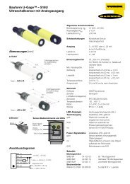
Green/Red<br />
Power/Signal<br />
Strength LED<br />
Push Button<br />
(IP67 models only)<br />
NOTE:<br />
• Exposure to direct sunlight can affect the sensor’s ability to accurately compensate for changes in temperature.<br />
• If the sensor is measuring across a temperature gradient, the compensation will be less effective.<br />
• The temperature warmup drift upon power-up is less than 7% of the sensing distance. After 5 minutes, the<br />
apparent switchpoint will be within 0.6% of the actual position. After 25 minutes, the sensing position will<br />
be stable.<br />
Figure 3. Sensor Features<br />
Yellow/Red<br />
TEACH/Output<br />
Indicator LED<br />
Two TEACH methods may be used to program the sensor:<br />
• Teach individual minimum and maximum limits, or<br />
• Use Auto-Window feature to center a sensing window around the taught position<br />
The sensor may be programmed either via its push button, or via a remote switch. Remote<br />
programming also may be used to disable the push button, preventing unauthorized<br />
personnel from adjusting the programming settings. To access this feature, connect<br />
the white wire of the sensor to 0V dc, with a remote programming switch between the<br />
sensor and the voltage.<br />
Programming is accomplished by following the sequence of input pulses (see programming procedures starting on page 4). The duration<br />
of each pulse (corresponding to a push button “click”), and the period between multiple pulses, are defined as “T”:<br />
Status Indicators<br />
Power ON/OFF<br />
LED<br />
Minimum<br />
Operating<br />
Range<br />
Dead Zone<br />
Target<br />
Near<br />
Setpoint<br />
0.04 seconds < T < 0.8 seconds<br />
Target<br />
Far<br />
Setpoint<br />
Power Output<br />
Power Output<br />
Power Output<br />
ON:<br />
Green<br />
OFF ON:<br />
Green<br />
ON:<br />
Yellow<br />
Figure 4. TEACH Interface<br />
Target<br />
ON:<br />
Green<br />
Indicates Output/Teach LED Indicates<br />
Maximum<br />
Operating<br />
Range<br />
Target<br />
Power<br />
OFF ON:<br />
Red<br />
OFF Power is OFF OFF Target is outside window limits (normally open<br />
operation).<br />
ON Red Target is weak or outside sensing<br />
range.<br />
Output<br />
Yellow Target is within window limits (normally open operaton).<br />
P/N 119287 Rev. F www.bannerengineering.com - tel: 763-544-3164 3<br />
OFF
Power ON/OFF<br />
LED<br />
Indicates Output/Teach LED Indicates<br />
ON Green Sensor is operating normally, good<br />
target.<br />
Teaching Minimum and Maximum Limits<br />
General Notes on Programming<br />
• The sensor will return to RUN mode if the first TEACH condition<br />
is not registered within 120 seconds.<br />
• After the first limit is taught, the sensor will remain in PROGRAM<br />
mode until the TEACH sequence is finished.<br />
• To exit PROGRAM mode without saving any changes, press and<br />
hold the programming push button > 2 seconds (before teaching<br />
the second limit). The sensor will revert to the last saved limits.<br />
Programming<br />
Mode<br />
Teach First<br />
Limit<br />
Teach Second<br />
Limit<br />
Push Button<br />
0.04 seconds ≤ "Click" ≤ 0.8 seconds<br />
• Press and hold push button<br />
• Position the target for the<br />
first limit<br />
ON Red (solid) In Teach Mode, waiting for first limit.<br />
ON Red (flashing) In Teach Mode, waiting for second limit.<br />
Normally Open Operation<br />
Minimum<br />
Limit<br />
Maximum<br />
Limit<br />
Output OFF Output ON Output OFF<br />
Normally Closed Operation<br />
Minimum<br />
Limit<br />
Maximum<br />
Limit<br />
Output ON Output OFF Output ON<br />
Figure 5. Teaching independent minimum and maximum<br />
limits<br />
Procedure Result<br />
Remote Line<br />
0.04 sec < T < 0.8 sec<br />
• No action required; sensor is ready<br />
for 1st limit teach<br />
• "Click" the push button • Single-pulse the remote line<br />
• Position the target for the<br />
second limit<br />
• "Click" the push button • Single-pulse the remote line<br />
Output LED: ON Red<br />
Power LED: ON Green (good<br />
signal) or ON Red (no signal)<br />
• Position the target for the first limit Power LED: Must be ON<br />
Green<br />
T<br />
Teach Accepted<br />
Output LED: Flashing Red<br />
Teach Unacceptable<br />
Output LED: ON Red<br />
• Position the target for the second limit Power LED: Must be ON<br />
Green<br />
T<br />
<strong>WORLD</strong>-<strong>BEAM</strong> <strong>QS18U</strong> <strong>Ultrasonic</strong> <strong>Sensors</strong><br />
Teach Accepted<br />
Output LED: Yellow or OFF<br />
Teach Unacceptable<br />
Output LED: Flashing Red<br />
4 www.bannerengineering.com - tel: 763-544-3164 P/N 119287 Rev. F
<strong>WORLD</strong>-<strong>BEAM</strong> <strong>QS18U</strong> <strong>Ultrasonic</strong> <strong>Sensors</strong><br />
Teaching Limits Using the Auto-Window Feature<br />
Position<br />
- 10 mm<br />
Output OFF Output ON Output OFF<br />
Position<br />
- 10 mm<br />
Normally Open Operation<br />
Taught Position<br />
Normally Closed Operation<br />
Taught Position<br />
Position<br />
+ 10 mm<br />
Position<br />
+ 10 mm<br />
Output ON Output OFF Output ON<br />
Figure 6. Using the Auto-Window feature for programming<br />
each output<br />
Programming<br />
Mode<br />
Teach First<br />
Limit<br />
Re-Teach<br />
Limit<br />
Push Button<br />
0.04 seconds ≤ "Click" ≤ 0.8 seconds<br />
• Press and hold push button<br />
• Position the target for the<br />
first limit<br />
Teaching the same limit twice automatically centers a 20 mm window<br />
on the taught position.<br />
General Notes on Programming<br />
• The sensor will return to RUN mode if the first TEACH condition<br />
is not registered within 120 seconds.<br />
• After the first limit is taught, the sensor will remain in PRO-<br />
GRAM mode until the TEACH sequence is finished.<br />
• To exit PROGRAM mode without saving any changes, press<br />
and hold the programming push button > 2 seconds (before<br />
teaching the second limit). The sensor will revert to the last<br />
saved program.<br />
Procedure Result<br />
Remote Line<br />
0.04 sec < T < 0.8 sec<br />
• No action required; sensor is ready<br />
for 1st limit teach<br />
• Position the target for the center of<br />
the window<br />
• "Click" the push button • Single-pulse the remote line<br />
• Without moving the target,<br />
"click" the push button<br />
again<br />
T<br />
• Without moving the target, singlepulse<br />
the remote line again<br />
T<br />
Output LED: ON Red<br />
Power LED: ON Green (good<br />
signal) or ON Red (no signal)<br />
Power LED: Must be ON<br />
Green<br />
Teach Accepted<br />
Output LED: Flashing Red<br />
Teach Unacceptable<br />
Output LED: ON Red<br />
Teach Accepted<br />
Output LED: Yellow or OFF<br />
Teach Unacceptable<br />
Output LED: Flashing Red<br />
P/N 119287 Rev. F www.bannerengineering.com - tel: 763-544-3164 5
Sensor<br />
Output<br />
ON<br />
Sensor<br />
Output<br />
OFF<br />
Near<br />
Range<br />
Any object in this area will switch<br />
the output, whether or not the object<br />
returns a good signal to the sensor.<br />
Position<br />
-10 mm<br />
Taught Position<br />
(background surface)<br />
Output OFF Output ON<br />
Sensing Distance<br />
Figure 7. An application for the Auto-Window feature (retroflective mode)<br />
Normally Open / Normally Closed Operation Select<br />
The sensor can be configured for either normally open or normally closed operation via the remote teach wire (white). A series of three<br />
pulses on the line will toggle between normally open and normally closed operation. Normally open is defined as the output energizing<br />
when the target is present. Normally closed is defined as the output energizing when the target is absent. See Figures 5 and 6.<br />
Toggle between<br />
N.O. / N.C.<br />
Operation<br />
Push Button Lockout<br />
Push Button<br />
0.04 seconds ≤ "Click" ≤ 0.8 seconds<br />
• Not available via push<br />
button<br />
Position<br />
+10 mm<br />
Procedure Result<br />
Remote Line<br />
0.04 sec < T < 0.8 sec<br />
• Triple-pulse the remote line<br />
T T<br />
Enables or disables the push button to prevent unauthorized personnel from adjusting the program settings.<br />
Push ButtonLockout<br />
Push Button<br />
0.04 seconds ≤ "Click" ≤ 0.8 seconds<br />
• Not available via push<br />
button<br />
T<br />
T<br />
T<br />
Either Normally Open or Normally<br />
Closed operation is selected,<br />
depending on previous<br />
condition.<br />
Procedure Result<br />
Remote Line<br />
0.04 sec < T < 0.8 sec<br />
• Four-pulse the remote line<br />
T T<br />
T T<br />
T T T<br />
<strong>WORLD</strong>-<strong>BEAM</strong> <strong>QS18U</strong> <strong>Ultrasonic</strong> <strong>Sensors</strong><br />
Push buttons are either enabled<br />
or<br />
disabled, depending on condition.<br />
6 www.bannerengineering.com - tel: 763-544-3164 P/N 119287 Rev. F
<strong>WORLD</strong>-<strong>BEAM</strong> <strong>QS18U</strong> <strong>Ultrasonic</strong> <strong>Sensors</strong><br />
Specifications<br />
Supply Voltage<br />
12 - 30V dc (10% maximum ripple); 25 mA max (exclusive<br />
of load)<br />
Supply Protection Circuitry<br />
Protected against reverse polarity and transient voltages<br />
Output Configuration<br />
SPST solid-state switch conducts when target is<br />
sensed within sensing window; one NPN (current sinking)<br />
or one PNP (current sourcing), depending on model.<br />
Rating: 100 mA maximum load; see Application Note 1<br />
Off-state leakage current: less than 10 µA (sourcing);<br />
less than 200 µA (sinking); see Application Note 2<br />
ON-state saturation voltage: NPN: less than 1.6V @<br />
100 mA; PNP: less than 3.0V @ 100 mA<br />
Output Response<br />
NOTE: 300 ms delay on power-up; output does not<br />
conduct during this time<br />
15 milliseconds<br />
Repeatability<br />
0.7 mm<br />
Indicators<br />
Range Indicator (Red/Green) and Teach/Output Indicator<br />
(Yellow/Red)<br />
Range Indicator: Green - Target is within sensing<br />
range; Red - Target is outside sensing range; OFF -<br />
Sensing Power is OFF<br />
Teach/Output Indicator: Yellow - Target is within<br />
taught limits; OFF - Target is outside taught window<br />
limits; Red - Sensor is in TEACH mode<br />
Sensor Response Curves<br />
Adjustments<br />
Sensing Window Limits: TEACH-mode programming of<br />
near and far window limits may be set using the push<br />
button or remotely via TEACH input<br />
Construction<br />
ABS housing, TPE Push Button, ABS Push Button<br />
housing, Polycarbonate lightpipes, leakproof design<br />
Connections<br />
2 m (6.5 ft) or 9 m (30 ft) 4-conductor PVC jacketed attached<br />
cable, or 4-pin Euro-style integral QD (Q8), or<br />
4-pin Pico-style integral QD (Q7), or 4-pin Euro-style<br />
150 mm (6 in) pigtail QD (Q5), or 4-pin Pico-style 150<br />
mm (6 in) pigtail QD (Q)<br />
Operating Conditions<br />
Relative Humidity: 100% @ 55° C (non-condensing)<br />
Temperature: − 20° to + 60° C (− 4° to + 140° F)<br />
Application Notes<br />
If supply voltage is > 24V dc, derate maximum output<br />
current 5 mA/°C above 50°C.<br />
NPN off-state leakage current is < 200 µA for load resistances<br />
> 3 kΩ or optically isolated loads. For load<br />
current of 100 mA, leakage is < 1% of load current.<br />
Objects passing inside the specified near limit may produce<br />
a false response.<br />
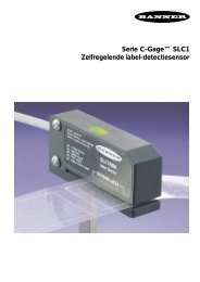
Certifications<br />
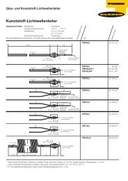
<strong>QS18U</strong> Effective Beam Pattern (Typical) <strong>QS18U</strong> Maximum Target Rotation Angle<br />
Lateral Distance (mm)<br />
50<br />
40<br />
30<br />
20<br />
10<br />
0<br />
-10<br />
-20<br />
-30<br />
-40<br />
-50<br />
Dimensions<br />
0 100 200 300 400 500<br />
Sensing Distance (mm) 2.5 mm rod<br />
8 mm rod<br />
50 mm x 50 mm plate<br />
Target Rotation<br />
15°<br />
10°<br />
5°<br />
0<br />
-5°<br />
-10°<br />
-15°<br />
0 100 200 300 400 500<br />
Sensing Distance (mm)<br />
P/N 119287 Rev. F www.bannerengineering.com - tel: 763-544-3164 7
15.0 mm<br />
(0.59")<br />
24.2 mm<br />
(0.95")<br />
Wiring<br />
Cabled Models Pico-Style QD Models Euro-Style QD Models<br />
17.1 mm<br />
(0.67")<br />
3 mm<br />
(0.12")<br />
33.5 mm<br />
(1.32")<br />
24.1 mm<br />
(0.95")<br />
35.0 mm<br />
(1.38")<br />
M18 x 1 Thread<br />
Max. Torque 2.3 Nm (20 in-lbs)<br />
ø 3.3 mm (0.13")<br />
Max. Torque 0.6 Nm (5 in-lbs)<br />
150 mm (6")<br />
Pico-style<br />
Pigtail<br />
41.5 mm<br />
(1.63")<br />
Integral<br />
4-pin<br />
Pico-Style QD<br />
Locknut (included with all models) Washer (included with all models)<br />
bn<br />
bu<br />
bk<br />
8.0 mm<br />
(0.32")<br />
Ø 23.9 mm<br />
(0.94")<br />
Ø 17.8 mm<br />
(0.70")<br />
1.6 mm<br />
(0.06")<br />
150 mm (6")<br />
Euro-style<br />
Pigtail<br />
49 mm<br />
(1.93")<br />
Integral<br />
4-pin<br />
Euro-Style QD<br />
M3 Hardware Packet Contents:<br />
• 2 – M3 x 0.5 x 20 mm SS Screw<br />
• 2 – M3 x 0.5 SS Hex Nut<br />
• 2 – M3 SS Washer<br />
NPN (Sinking) Output Models PNP (Sourcing) Output Models<br />
wh<br />
shield<br />
Load<br />
12 - 30V dc<br />
Remote programming<br />
switch (normally open)<br />
bn<br />
bu<br />
bk<br />
Load<br />
wh<br />
shield<br />
12 - 30V dc<br />
Remote programming<br />
switch (normally open)<br />
Cable and QD hookups are functionally identical. It is recommended that the shield wire be connected to earth ground. Shielded<br />
cordsets are recommended for all QD models.<br />
Quick-Disconnect (QD) Cordsets<br />
4-Pin Snap-On M8/Pico-Style Cordsets with Shield<br />
Model Length Style Dimensions Pinout<br />
PKG4S-2 2.00 m (6.56 ft) Straight ø10 mm max.<br />
(0.4")<br />
28 mm max.<br />
(1.1")<br />
<strong>WORLD</strong>-<strong>BEAM</strong> <strong>QS18U</strong> <strong>Ultrasonic</strong> <strong>Sensors</strong><br />
4<br />
3<br />
1 = Brown<br />
2 = White<br />
3 = Blue<br />
4 = Black<br />
8 www.bannerengineering.com - tel: 763-544-3164 P/N 119287 Rev. F<br />
2<br />
1
<strong>WORLD</strong>-<strong>BEAM</strong> <strong>QS18U</strong> <strong>Ultrasonic</strong> <strong>Sensors</strong><br />
4-Pin Snap-On M8/Pico-Style Cordsets with Shield<br />
Model Length Style Dimensions Pinout<br />
PKW4ZS-2 2.00 m (6.56 ft) Right Angle<br />
4-Pin Threaded M12/Euro-Style Cordsets with Shield<br />
25 mm max.<br />
(1.0")<br />
ø12 mm max.<br />
(0.5")<br />
Model Length Style Dimensions Pinout<br />
MQDEC2-406 1.83 m (6 ft) Straight<br />
MQDEC2-415 4.57 m (15 ft)<br />
MQDEC2-430 9.14 m (30 ft)<br />
MQDEC2-406RA 1.83 m (6 ft) Right-Angle<br />
MQDEC2-415RA 4.57 m (15 ft)<br />
MQDEC2-430RA 9.14 m (30 ft)<br />
Mounting Brackets<br />
SMB18A<br />
SMBQS18RA<br />
SMB18SF<br />
SMB18UR<br />
44 mm max.<br />
(1.7")<br />
M12 x 1<br />
ø 14.5 [0.57"]<br />
32 Typ.<br />
[1.26"]<br />
• Right-angle mounting bracket with a<br />
curved slot for versatile orientation<br />
• 12-ga. stainless steel<br />
• 18 mm sensor mounting hole<br />
• Clearance for M4 (#8) hardware<br />
• Right-angle mounting bracket<br />
• 14-ga. 304 stainless steel<br />
20 mm<br />
(0.8")<br />
• 18 mm swivel bracket with M18 x 1 internal<br />
thread<br />
• Black thermoplastic polyester<br />
• Stainless steel swivel locking hardware<br />
included<br />
• 2-piece universal swivel bracket<br />
• 300 series stainless steel<br />
ø 15 mm<br />
(0.6")<br />
M12 x 1<br />
30 Typ.<br />
[1.18"]<br />
1<br />
4<br />
1 = Brown<br />
2 = White<br />
3 = Blue<br />
4 = Black<br />
P/N 119287 Rev. F www.bannerengineering.com - tel: 763-544-3164 9<br />
2<br />
3
• Stainless steel swivel locking hardware<br />
included<br />
• Mounting hole for 18 mm sensor<br />
<strong>WORLD</strong>-<strong>BEAM</strong> <strong>QS18U</strong> <strong>Ultrasonic</strong> <strong>Sensors</strong><br />
<strong>Banner</strong> <strong>Engineering</strong> Corp Limited Warranty<br />
<strong>Banner</strong> <strong>Engineering</strong> Corp. warrants its products to be free from defects in material and workmanship for one year following the date of<br />
shipment. <strong>Banner</strong> <strong>Engineering</strong> Corp. will repair or replace, free of charge, any product of its manufacture which, at the time it is returned<br />
to the factory, is found to have been defective during the warranty period. This warranty does not cover damage or liability for misuse,<br />
abuse, or the improper application or installation of the <strong>Banner</strong> product.<br />
THIS LIMITED WARRANTY IS EXCLUSIVE AND IN LIEU OF ALL OTHER WARRANTIES WHETHER EXPRESS OR IMPLIED (IN-<br />
CLUDING, WITHOUT LIMITATION, ANY WARRANTY OF MERCHANTABILITY OR FITNESS FOR A PARTICULAR PURPOSE), AND<br />
WHETHER ARISING UNDER COURSE OF PERFORMANCE, COURSE OF DEALING OR TRADE USAGE.<br />
This Warranty is exclusive and limited to repair or, at the discretion of <strong>Banner</strong> <strong>Engineering</strong> Corp., replacement. IN NO EVENT SHALL<br />
BANNER ENGINEERING CORP. BE LIABLE TO BUYER OR ANY OTHER PERSON OR ENTITY FOR ANY EXTRA COSTS, EXPEN-<br />
SES, LOSSES, LOSS OF PROFITS, OR ANY INCIDENTAL, CONSEQUENTIAL OR SPECIAL DAMAGES RESULTING FROM ANY<br />
PRODUCT DEFECT OR FROM THE USE OR INABILITY TO USE THE PRODUCT, WHETHER ARISING IN CONTRACT OR WAR-<br />
RANTY, STATUTE, TORT, STRICT LIABILITY, NEGLIGENCE, OR OTHERWISE.<br />
<strong>Banner</strong> <strong>Engineering</strong> Corp. reserves the right to change, modify or improve the design of the product without assuming any obligations or<br />
liabilities relating to any product previously manufactured by <strong>Banner</strong> <strong>Engineering</strong> Corp.<br />
www.bannerengineering.com - tel: 763-544-3164