B338+AFRX24-MFT-S Technical Data Sheet - HVAC Control Store
B338+AFRX24-MFT-S Technical Data Sheet - HVAC Control Store
B338+AFRX24-MFT-S Technical Data Sheet - HVAC Control Store

Create successful ePaper yourself
Turn your PDF publications into a flip-book with our unique Google optimized e-Paper software.
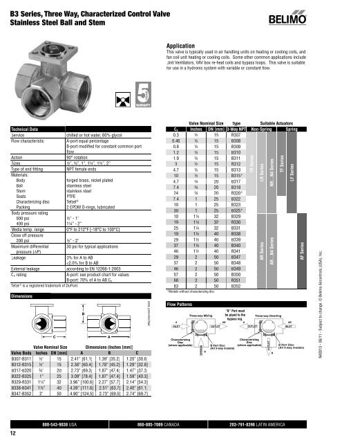
B3 Series, Three Way, Characterized <strong>Control</strong> Valve<br />
Stainless Steel Ball and Stem<br />
<strong>Technical</strong> <strong>Data</strong><br />
Service chilled or hot water, 60% glycol<br />
Flow characteristic A-port equal percentage<br />
B-port modifi ed for constant common port<br />
fl ow<br />
Action 90° rotation<br />
Sizes ½”, ¾”, 1”, 1¼”, 1½”, 2”<br />
Type of end fi tting NPT female ends<br />
Materials:<br />
Body<br />
Ball<br />
Stem<br />
Seats<br />
Characterizing disc<br />
Packing<br />
Body pressure rating<br />
600 psi<br />
400 psi<br />
12<br />
forged brass, nickel plated<br />
stainless steel<br />
stainless steel<br />
PTFE<br />
Tefzel ®<br />
2 EPDM O-rings, lubricated<br />
½” - 1”<br />
1¼” - 2”<br />
Media temp. range 0°F to 212°F [-18°C to 100°C]<br />
Close off pressure<br />
200 psi ½” - 2”<br />
Maximum differential 30 psi for typical applications<br />
pressure (ΔP)<br />
Leakage 0% for A to AB<br />
AFRX Actuators, Multi-Function Technology<br />
Models<br />
AFRX24-<strong>MFT</strong><br />
AFRX24-<strong>MFT</strong>-S<br />
AFRX24-<strong>MFT</strong>-5-14<br />
AFRX24-<strong>MFT</strong>-S-5-14<br />
<strong>Technical</strong> <strong>Data</strong><br />
<strong>Control</strong> <strong>MFT</strong><br />
<strong>Control</strong> signal 2 to 10 VDC, 4 to 20 mA (default)<br />
variable (VDC, PWM, fl oating point, on/off)<br />
Power supply 24 VAC, +/- 20%, 50/60 Hz<br />
24 VDC, +20% / -10%<br />
Power consumption† running 7.5 W<br />
holding 3 W<br />
Transformer sizing† 10 VA (Class 2 power source)<br />
Electrical connection 3 ft. [1m], 10 ft. [3m] or 16 ft. [5m] 18 GA<br />
appliance or plenum cables, with or without<br />
1/2" conduit connector<br />
-S models: two 3 ft. [1m], 10 ft. [3m] or 16<br />
ft. [5m] appliance cables with or without 1/2”<br />
conduit connectors<br />
Overload protection electronic throughout 0 to 90° rotation<br />
Feedback output* 2 to 10 VDC, 0.5 mA max (variable)<br />
Input impedance 100 kΩ for 2 to 10 VDC (0.1 mA)<br />
500 Ω for 4 to 20 mA<br />
1500 Ω for on/off and fl oating point<br />
Angle of rotation 95°<br />
Direction of rotation* spring reversible with CW/CCW mounting<br />
motor reversible with built-in<br />
Position indication visual indicator 0° to 95°(0° is spring return<br />
position)<br />
Manual override 5 mm hex crank (3/16” Allen), supplied<br />
Running time motor* 150 seconds (default),<br />
variable (70 to 220 seconds)<br />
spring
N40013 - 06/11 - Subject to change. © Belimo Aircontrols (USA), Inc.<br />
Dimensions<br />
Valve<br />
Body<br />
C<br />
Nominal<br />
Pipe<br />
Size<br />
B6250 2½" [65]<br />
3.93”<br />
[99.9]<br />
9.77”<br />
[248.2]<br />
Top<br />
Flange<br />
Design<br />
2.50”<br />
[63.5]<br />
Flange<br />
Diameter<br />
Face-to-Face<br />
Length<br />
Height<br />
A B C<br />
7.50" [190.5] 5.50" [139.7] 8.10" [205.4]<br />
B6300 3" [80] F05 8.00" [203.2] 6.60" [167.6] 8.40" [213.1]<br />
B6400 4" [100] 9.00" [228.6] 8.30" [210.8] 9.30" [235.9]<br />
Wiring Diagrams<br />
B<br />
1 Provide overload protection and disconnect as required.<br />
2<br />
CAUTION Equipment Damage!<br />
Actuators may be connected in parallel if not mechanically mounted<br />
to the same shaft. Power consumption and input impedance must be<br />
observed.<br />
3 Actuators may also be powered by 24 VDC.<br />
Position feedback cannot be used with Triac sink controller.<br />
4 The actuator internal common reference is not compatible.<br />
<strong>Control</strong> signal may be pulsed from either the Hot (source)<br />
5 or the Common (sink) 24 VAC line.<br />
Contact closures A & B also can be triacs.<br />
8 A & B should both be closed for triac source and open for triac sink.<br />
For triac sink the common connection from the actuator<br />
9 must be connected to the hot connection of the controller.<br />
4.04”<br />
[102.7]<br />
Meets UL requirements without the need of an electrical ground<br />
connection.<br />
The ZG-R01 500 Ω resistor may be used.<br />
WARNING Live Electrical Components!<br />
During installation, testing, servicing and troubleshooting of this product, it may be<br />
necessary to work with live electrical components. Have a qualifi ed licensed electrician<br />
or other individual who has been properly trained in handling live electrical components<br />
perform these tasks. Failure to follow all electrical safety precautions when exposed to<br />
live electrical components could result in death or serious injury.<br />
A<br />
AFR_LGCCV<br />
AFRX Actuators, Multi-Function Technology<br />
Auxiliary Switches for AFRX24-<strong>MFT</strong><br />
VDC/4-20 mA<br />
AFB24-<strong>MFT</strong>-S<br />
AFX24-<strong>MFT</strong>-S<br />
800-543-9038 USA 866-805-7089 CANADA 203-791-8396 LATIN AMERICA<br />
PWM<br />
On/Off Off control l<br />
Floating Point control<br />
W600_AFB_AFX<br />
W399_08<br />
W399_08<br />
W399_08<br />
W399_08<br />
93