Custom Micro-D connectors - Axon' Cable
Custom Micro-D connectors - Axon' Cable
Custom Micro-D connectors - Axon' Cable

You also want an ePaper? Increase the reach of your titles
YUMPU automatically turns print PDFs into web optimized ePapers that Google loves.
CUSTOM MICRO-D<br />
SOLUTIONS<br />
CUSTOM DESIGN CONNECTORS<br />
<strong>Custom</strong> design <strong>connectors</strong> . . . . . . . . . . . . . . . . . . . . . . . . . . . . . . . . 206<br />
Materials & finishes . . . . . . . . . . . . . . . . . . . . . . . . . . . . . . . . . . . . 207<br />
69 and 74 way <strong>Micro</strong>-D <strong>connectors</strong> . . . . . . . . . . . . . . . . . . . . . . . . 208<br />
Surface mount <strong>connectors</strong> . . . . . . . . . . . . . . . . . . . . . . . . . . . . . . . . 210<br />
<strong>Custom</strong> designed shells and hardware . . . . . . . . . . . . . . . . . . . . . . . 211<br />
EMI & panel mount <strong>connectors</strong> . . . . . . . . . . . . . . . . . . . . . . . . . . . . 212<br />
Filtered <strong>Micro</strong>-D <strong>connectors</strong> . . . . . . . . . . . . . . . . . . . . . . . . . . . . . . . 214<br />
Termination with flex circuits . . . . . . . . . . . . . . . . . . . . . . . . . . . . . 226<br />
Waterproof & hermetic <strong>connectors</strong> . . . . . . . . . . . . . . . . . . . . . . . . . 227<br />
High-density <strong>connectors</strong> . . . . . . . . . . . . . . . . . . . . . . . . . . . . . . . . . 230<br />
Non magnetic <strong>Micro</strong>-D interconnect solutions . . . . . . . . . . . . . . . . . 240<br />
FROM CUSTOM DESIGN ASSEMBLIES TO MINI-SYSTEMS<br />
From assemblies to mini systems . . . . . . . . . . . . . . . . . . . . . . . . . . 242<br />
Our harnessing capabilities . . . . . . . . . . . . . . . . . . . . . . . . . . . . . . . 243<br />
Technical solutions for assemblies . . . . . . . . . . . . . . . . . . . . . . . . . 244<br />
Overmoulding expertise . . . . . . . . . . . . . . . . . . . . . . . . . . . . . . . . . 245<br />
SILFORM ® cables & assemblies . . . . . . . . . . . . . . . . . . . . . . . . . . . 247<br />
Mini-systems : complete solutions . . . . . . . . . . . . . . . . . . . . . . . . . . 248<br />
<strong>Custom</strong> <strong>Micro</strong>-D<br />
solutions<br />
www.axon-cable.com - www.microd-<strong>connectors</strong>.com © 2002, AXON’ CABLE SAS - AXON’ D-LINE ® - RELEASED JUNE 2010 205
<strong>Custom</strong> <strong>Micro</strong>-D<br />
solutions<br />
206<br />
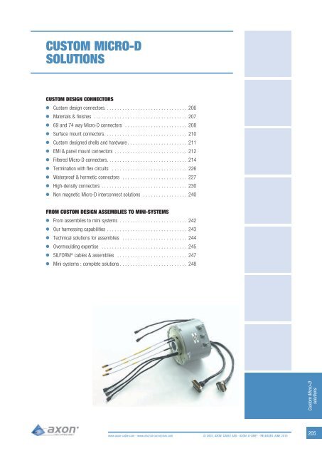
<strong>Custom</strong> designed<br />
solutions<br />
CUSTOM DESIGN<br />
CONNECTORS<br />
In addition to the standard range of <strong>Micro</strong>-D <strong>connectors</strong> and assemblies, AXON’ can<br />
develop custom designed solutions, all based on <strong>Micro</strong>-D twist-pin contact technology<br />
. AXON’ is the sole manufacturer in Europe to have fully integrated in-house the<br />
design and the manufacture of the <strong>Micro</strong>-D system, including :<br />
- Twist pins, shells, inserts and interfacial seals .<br />
- <strong>Custom</strong> designed conductors, wires and cables .<br />
- Complex assembly processes including optimised EMC shielding, branch braiding<br />
and overmoulding .<br />
This high level of vertical integration enables AXON’ to offer complete solutions which<br />
meet the demanding requirements of the aeronautics, space, military, industrial and<br />
off-shore markets .<br />
Common applications<br />
MIL-AERO<br />
- Missiles and counter measures .<br />
- Electro-optics .<br />
- Navigation systems .<br />
- Avionics equipment .<br />
- Radar systems .<br />
- Twist capsules .<br />
- Shoulder launched weapon systems .<br />
- Advanced soldier technology systems .<br />
- Military GPS systems .<br />
NON MILITARY<br />
- Down-hole drilling tools .<br />
- Automotive test equipment .<br />
- Medical devices .<br />
- Ruggedised computers .<br />
- Research centres .<br />
SPACE<br />
- Satellite electronics .<br />
- Space station and planetary explorer applications .<br />
© 2002, AXON’ CABLE SAS - AXON’ D-LINE ® - RELEASED JUNE 2010 www.axon-cable.com - www.microd-<strong>connectors</strong>.com
<strong>Custom</strong> designed<br />
solutions<br />
MATERIAL<br />
ALUMINIUM<br />
6061<br />
STAINLESS<br />
STEEL SERIES<br />
300<br />
MATERIALS & FINISHES<br />
AXON’ can offer micro-D solutions with standard<br />
and special shell materials and<br />
finishes . The table below illustrates some of the<br />
more common options, however other materials<br />
and finishes may be possible on request :<br />
IN<br />
ACCORDANCE<br />
WITH<br />
SAE<br />
AMS-QQ-A-250/11<br />
DENSITY<br />
(g/cm3)<br />
2 .7<br />
- 7 .8<br />
FINISH<br />
STANDARD MIL-DTL-83513<br />
FINISHES<br />
- CADMIUM WITH YELLOW<br />
CHROMATE OVER<br />
ELECTROLESS NICKEL<br />
- ELECTROLESS NICKEL<br />
SPECIAL FINISHES<br />
- CADMIUM WITH YELLOW<br />
CHROMATE OVER<br />
ELECTROLESS NICKEL<br />
- HEAVY ELECTROLESS NICKEL<br />
- BLACK ANODISATION<br />
(IN ACCORDANCE WITH<br />
MIL-A-8625 TYPE II CLASS 2)<br />
- CHEMICAL FILM<br />
IN ACCORDANCE WITH<br />
MIL-C-5541 CLASS 3<br />
- GOLD PLATING<br />
IN ACCORDANCE WITH<br />
ASTM-B-488<br />
OVER ELECTROLESS NICKEL<br />
PASSIVATION IN ACCORDANCE<br />
WITH SAE AMS-27000<br />
SALT SPRAY<br />
RESISTANCE<br />
(IN<br />
ACCORDANCE<br />
WITH<br />
EIA-364-26)<br />
96 HOURS<br />
48 HOURS<br />
500 HOURS<br />
500 HOURS<br />
48 HOURS<br />
48 HOURS<br />
48 HOURS<br />
TEMPERATURE<br />
RANGE<br />
MISCELLANEOUS<br />
<strong>Custom</strong> <strong>Micro</strong>-D<br />
solutions<br />
www.axon-cable.com - www.microd-<strong>connectors</strong>.com © 2002, AXON’ CABLE SAS - AXON’ D-LINE ® - RELEASED JUNE 2010 207<br />
150°C<br />
200°C<br />
150°C<br />
200°C<br />
150°C<br />
150°C<br />
150°C<br />
1000 HOURS 200°C<br />
TITANIUM - 4 .5 NONE 500 HOURS 200°C<br />
KOVAR<br />
(Fe/Ni/Co<br />
ALLOY)<br />
- 8 .4<br />
ELECTROLYTIC<br />
NICKEL<br />
SALT SPRAY TEST EQUIPMENT<br />
MILITARY<br />
APPLICATIONS<br />
MOST COMMON<br />
PLATING<br />
MILITARY<br />
APPLICATIONS<br />
MILITARY & SPACE<br />
APPLICATIONS<br />
NON-REFLECTIVE /<br />
POOR CONDUCTIVITY<br />
NON MAGNETIC<br />
APPLICATIONS<br />
SPACE GRADE<br />
APPLICATIONS<br />
EXCELLENT<br />
CORROSION<br />
RESISTANCE<br />
ALL ROUND<br />
PERFORMANCE WEIGHT,<br />
CORROSION, EMC<br />
48 HOURS 200°C HERMETIC<br />
APPLICATIONS
<strong>Custom</strong> <strong>Micro</strong>-D<br />
solutions<br />
208<br />
<strong>Custom</strong> designed<br />
solutions<br />
69 AND 74 WAY<br />
MICRO-D CONNECTORS<br />
AXON’ offers specific contact arrangements for custom applications . Specific designs are not covered<br />
by the MIL-DTL-83513 specification but AXON’s <strong>connectors</strong> remain fully compatible with the<br />
MIL-DTL-83513 standard as far as performance and construction are concerned .<br />
Contact arrangements<br />
MATING FACE OF 69 WAY MALE CONNECTOR<br />
MATING FACE OF 74 WAY MALE CONNECTOR<br />
1 .27 mm ( .050’’) contact spacing .<br />
1 .09 mm ( .043’’) spacing between rows .<br />
Electrical & mechanical<br />
characteristics<br />
As per MIL-DTL-83513<br />
Materials<br />
As per MIL-DTL-83513<br />
© 2002, AXON’ CABLE SAS - AXON’ D-LINE ® - RELEASED JUNE 2010 www.axon-cable.com - www.microd-<strong>connectors</strong>.com<br />
MATING FACE OF 69 WAY FEMALE CONNECTOR<br />
MATING FACE OF 74 WAY FEMALE CONNECTOR<br />
SEE PAGE 15 FOR MORE INFORMATION<br />
SEE PAGE 15 FOR MORE INFORMATION
69P/69S<br />
74P/74S<br />
A<br />
± 0.25<br />
(±.010)<br />
43 .82<br />
1 .725<br />
38 .74<br />
1 .525<br />
Dimensions<br />
Dimensions are in millimetres (inches) .<br />
B max C<br />
D E<br />
F max<br />
Male female<br />
-0.46/+0.25<br />
(-.018/+.010)<br />
± 0.13<br />
(±.005)<br />
± 0.25<br />
(±.010) Male female<br />
32 .61<br />
1 .284<br />
27 .53<br />
1 .084<br />
34 .29<br />
1 .350<br />
29 .22<br />
1 .150<br />
34 .04<br />
1 .340<br />
28 .96<br />
1 .140<br />
38 .48<br />
1 .515<br />
33 .40<br />
1 .315<br />
Available versions<br />
metal shell only<br />
- Male pigtail<br />
- Female pigtail<br />
- Saver<br />
- PCB <strong>connectors</strong> (available on request)<br />
69 WAY MICRO-D PIGTAIL CONNECTORS<br />
8 .66<br />
.431<br />
9 .75<br />
.384<br />
5 .79<br />
.228<br />
6 .88<br />
.271<br />
7 .44<br />
.293<br />
8 .46<br />
.333<br />
G max<br />
7 .87<br />
.310<br />
9 .14<br />
.360<br />
74 WAY MICRO-D PIGTAIL CONNECTORS<br />
<strong>Custom</strong> <strong>Micro</strong>-D<br />
solutions<br />
www.axon-cable.com - www.microd-<strong>connectors</strong>.com © 2002, AXON’ CABLE SAS - AXON’ D-LINE ® - RELEASED JUNE 2010 209
<strong>Custom</strong> <strong>Micro</strong>-D<br />
solutions<br />
210<br />
<strong>Custom</strong> designed<br />
solutions<br />
SURFACE MOUNT<br />
CONNECTORS<br />
Surface mount <strong>connectors</strong> are becoming a new industry standard for saving space<br />
between electronic Printed Circuit Boards . In comparison with a classic right angled PCB<br />
connector (BR), a surface mount connector mounted on the edge of a PCB can greatly<br />
reduce the overall space envelope required, both in surface area and in height . Thus,<br />
electronic cards can be higher in component density, and stacked more closely than<br />
before .<br />
Surface mount <strong>connectors</strong> are available in 3 versions : SMV (Surface Mount Vertical), SMT<br />
(Surface Mount Transversal - on the edge of the card) and SMH (Surface Mount Horizontal) . All<br />
three styles usually have gold plated tails with a spacing of 0 .635 mm ( .025”) .<br />
AXON’ offers various hardware options, either the classic jackposts and jackscrews, or<br />
more specialised options such as keying hardware .<br />
AXON’ Surface Mount Connectors are typically compatible with PCB’s having a thickness<br />
of between 1 .6 and 3 .2 mm ( .063 to .126”) .<br />
However, AXON’ can study custom surface mount <strong>connectors</strong> to meet your specific application<br />
and space requirements .<br />
37 WAY SMH CONNECTOR<br />
© 2002, AXON’ CABLE SAS - AXON’ D-LINE ® - RELEASED JUNE 2010 www.axon-cable.com - www.microd-<strong>connectors</strong>.com<br />
’s<br />
51 WAY SMT CONNECTOR PCB MOUNT<br />
SPECIAL 31 WAY SMH CONNECTOR<br />
51 WAY SMT CONNECTOR<br />
37 WAY SMH CONNECTOR
<strong>Custom</strong> designed<br />
solutions<br />
CUSTOM DESIGNED<br />
SHELLS & HARDWARE<br />
Your system or application may be highly specialised in size, shape, performance or<br />
construction, and for this reason the standard <strong>Micro</strong>-D shell sizes may not be suitable .<br />
Meeting the challenge, AXON’ can adapt existing shells or produce custom design<br />
<strong>Micro</strong>-D shells to meet your specific mechanical and environmental requirements .<br />
Design and manufacturing expertise on the same site makes it possible for AXON’ to<br />
offer you a quick turnaround .<br />
As we design and manufacture all the different component parts in-house, we can offer<br />
quick design solutions for small series and large volumes .<br />
AXON’ is also able to develop and manufacture special hardware, such as retractable<br />
or captive screws, threaded inserts, and other configurations as required .<br />
MICRO-D WITH SPECIAL<br />
INTEGRATED BACKSHELL<br />
FOR FLAT CABLE<br />
EXAMPLES OF MICRO D SHAPE FULLY INTEGRATED INTO AN ELECTRONIC BOX COVER<br />
TO ELIMINATE RF/EMI LEAKAGE IN COMPARISON TO A CLASSIC PANEL MOUNT CONNECTOR<br />
1<br />
1 - High position to facilitate the mating<br />
2 - Low position to lock the connector<br />
CUSTOM MICRO-D DESIGN<br />
51 WAY SAVER WITH CUSTOM RETRACTABLE SCREWS<br />
<strong>Custom</strong> <strong>Micro</strong>-D<br />
solutions<br />
www.axon-cable.com - www.microd-<strong>connectors</strong>.com © 2002, AXON’ CABLE SAS - AXON’ D-LINE ® - RELEASED JUNE 2010 211<br />
2
<strong>Custom</strong> <strong>Micro</strong>-D<br />
solutions<br />
212<br />
<strong>Custom</strong> designed<br />
solutions<br />
SILVER PLATED FLANGE MICRO-D<br />
WITH EMI 0-RING AND 360° SCREEN<br />
TERMINATION TO EMI BACKSHELL<br />
EMI & PANEL MOUNT<br />
CONNECTORS<br />
EMI protection is a key issue for all electronics devices . Since the mid eighties AXON’<br />
has had a dedicated team of engineers who specialise in this field . The AXON’ EMI<br />
Team has developed simulation software to predict the transfer impedance (or shield<br />
efficiency) of a connector, a cable or a complete cable assembly during the design<br />
phase before any manufacturing commences .<br />
Product tests in AXON’s stirred mode chamber and transfer impedance test bench<br />
validate the simulated results . Simulation is an excellent tool to optimise a design in<br />
order to provide the best compromise between performance, weight and cost . Such<br />
simulation has proven over the years that a good component is not enough to ensure<br />
good EMI performance . In addition, it is essential to ensure the right combination and<br />
compatibility between connector, cable and the shield termination to the backshell .<br />
The AXON’ <strong>Micro</strong>-D backshells are specifically designed to perfectly fit the connector<br />
and prevent EMI leakage . Many other micro-D backshells are simply maintained<br />
against the connector by the hardware, but these solutions do not offer optimised EMI<br />
performance .<br />
On request, the flange of a panel mount connector can incorporate a groove which<br />
enables an EMI o-ring or gasket to be fitted . In this case the flanges are wider than<br />
for normal <strong>connectors</strong> .<br />
© 2002, AXON’ CABLE SAS - AXON’ D-LINE ® - RELEASED JUNE 2010 www.axon-cable.com - www.microd-<strong>connectors</strong>.com<br />
CUSTOM ANGLED EMI BACKSHELL LARGE FLANGE MICRO-D PIGTAILS<br />
WITH EMI GASKET GROOVES (51 WAY ON THE LEFT HAND<br />
SIDE, 25 WAY ON THE RIGHT HAND SIDE)
STIRRED MODE CHAMBER<br />
EMI SOLUTIONS<br />
AXON’ has drawn on long experience in<br />
the fields of RF and EMI protection to<br />
design and adapt the <strong>Micro</strong>-D connector<br />
to meet the most challenging of EMI<br />
environments . EMI customisation of the<br />
standard micro system can include :<br />
- EMI gaskets or o-rings<br />
- Special backshells<br />
- Special connector shell designs<br />
- Special finishes<br />
- Optimised shield termination to the backshell .<br />
HIGH PERFORMANCE EMI HARNESS<br />
- 2 part self locking EMI backshell<br />
- optimised shielding<br />
- 360° screen termination<br />
- EMI gasket<br />
- special technical solutions for better EMI protection<br />
EMI BACKSHELL ON ITS OWN, AND FITTED<br />
TO A MICRO-D WITH SHIELD TERMINATION TO CABLE<br />
AND OVERALL PROTECTION<br />
2 PART SELF-LOCKING 45° EMI BACKSHELL WITH<br />
LARGE FLANGE MICRO-D CONNECTOR<br />
MEASUREMENT OF TRANSFER IMPEDANCE<br />
<strong>Custom</strong> <strong>Micro</strong>-D<br />
solutions<br />
www.axon-cable.com - www.microd-<strong>connectors</strong>.com © 2002, AXON’ CABLE SAS - AXON’ D-LINE ® - RELEASED JUNE 2010 213
<strong>Custom</strong> <strong>Micro</strong>-D<br />
solutions<br />
214<br />
<strong>Custom</strong> designed<br />
solutions<br />
FILTERED MICRO-D<br />
CONNECTORS<br />
Integrated systems require more power with major current fluctuations, creating a “noisy”<br />
electromagnetic field . Filtered <strong>Micro</strong>-D <strong>connectors</strong> are designed to protect your equipment<br />
from this electromagnetic interference .<br />
General configuration<br />
Axon’ filtered <strong>Micro</strong>-D <strong>connectors</strong> are available with two different types of filters: C filter<br />
and PI filter, both low-pass . High frequency signals are attenuated, whilst low frequency<br />
and DC signals pass through .<br />
C FILTER<br />
- One capacitor per filtered pin .<br />
- Best suited for high input and output impedance and when a fast attenuation is not<br />
necessary .<br />
- When small size is needed .<br />
PI FILTER<br />
- Two capacitors on either side of an inductor per filtered pin .<br />
- Used for high impedance and a sharp attenuation .<br />
- Performances at high frequency are excellent .<br />
15 WAY PI FILTERED FEMALE<br />
PIGTAIL<br />
© 2002, AXON’ CABLE SAS - AXON’ D-LINE ® - RELEASED JUNE 2010 www.axon-cable.com - www.microd-<strong>connectors</strong>.com<br />
9 WAY PI FILTERED BS FEMALE CONNECTOR<br />
37 WAY C FILTERED CBR FEMALE CONNECTOR
Electrical & mechanical<br />
characteristics<br />
CHARACTERISTIC SPECIFICATION TEST METHOD<br />
CURRENT RATING 3 A max . EIA-364-70<br />
SIGNAL CONTACT RESISTANCE 8 mΩ max . EIA-364-06<br />
INSULATION RESISTANCE 5000 MΩ min . @ 500 V DC EIA-364-21<br />
DIELECTRIC WITHSTANDING VOLTAGE<br />
- SEA LEVEL 0 m<br />
CONTACT ENGAGING AND<br />
SEPARATION FORCE<br />
125V DC EIA-364-20<br />
170 g max . (6 oz)<br />
14 g min . (0 .5 oz)<br />
Material & Finish<br />
EIA-364-37<br />
CONNECTOR MATING AND<br />
DE-MATING FORCE<br />
283 g (10 oz) x number of contacts max . EIA-364-13<br />
CONTACT RETENTION 2 .26 kg (5 lbs) for 5 seconds min . EIA-364-29<br />
DURABILITY<br />
TEMPERATURE RANGES<br />
500 mating cycles min . EIA-364-09<br />
- STANDARD -55°C / +125°C<br />
VIBRATION 20 g’s -No discontinuity >1µs EIA-364-28 -TEST CONDITION IV<br />
SHOCK 50 g’s -No discontinuity >1µs EIA-364-27 -TEST CONDITION E<br />
SALT SPRAY 48 hours EIA-364-26 -TEST CONDITION B<br />
HUMIDITY Insulation resistance > 1MΩ EIA-364-31 - METHOD IV<br />
COMPONENT MATERIAL FINISH<br />
MALE CONTACT (TWIST PIN) COPPER AND BERYLLIUM COPPER . GOLD PLATING IN ACCORDANCE WITH ASTM-B488, TYPE II,<br />
CLASS 1 (1 .27µm (0 .050”) MIN .), CODE C<br />
FEMALE CONTACT COPPER ALLOY<br />
CAPACITORS PLANAR CERAMIC ARRAY<br />
INDUCTORS FERRITE<br />
METAL SHELL<br />
PLASTIC SHELL/ INSERT /<br />
PCB TRAY<br />
ALUMINIUM ALLOY, TYPE 6061<br />
IN ACCORDANCE WITH SAE-AMS-QQ-A-250/11<br />
OVER NICKEL UNDERPLATE IN ACCORDANCE WITH SAE-AMS-QQ-N-290<br />
CLASS 2 (1 .27µm (0 .050”) TO 3 .81µm (0 .150”) )<br />
YELLOW CHROMATE OVER CADMIUM : IN ACCORDANCE WITH<br />
SAE-AMS-QQ-P-416, TYPE II, CLASS 3<br />
ELECTROLESS NICKEL PLATING IN ACCORDANCE WITH<br />
SAE-AMS2404, CLASS 3 OR 4, .0005 INCH MIN .<br />
STAINLESS STEEL, 300 SERIES PASSIVATION IN ACCORDANCE WITH SAE-AMS2700<br />
LIQUID CRYSTAL POLYMER, 30% LOADED GLASS FIBRE<br />
POLYESTER, 94VO, IN ACCORDANCE WITH MIL-M-24519 (200°C)<br />
INTERFACIAL SEAL FLUOROSILICONE RUBBER IN ACCORDANCE WITH A-A-59588<br />
HARDWARE STAINLESS STEEL, 300 SERIES PASSIVATION IN ACCORDANCE WITH SAE-AMS2700<br />
ENCAPSULANT EPOXY RESIN<br />
INSULATED WIRE<br />
PTFE INSULATED SILVER PLATED COPPER IN ACCORDANCE WITH NEMA-HP3<br />
PTFE INSULATED SILVER PLATED COPPER IN ACCORDANCE WITH SAE-AS22759/11<br />
ETFE INSULATED SILVER PLATED COPPER IN ACCORDANCE WITH SAE-AS22759/33<br />
UNINSULATED WIRE<br />
GOLD PLATED SOLID COPPER WIRE IN ACCORDANCE WITH A-A-59551<br />
TIN PLATED SOLID COPPER WIRE IN ACCORDANCE WITH A-A-59551<br />
<strong>Custom</strong> <strong>Micro</strong>-D<br />
solutions<br />
www.axon-cable.com - www.microd-<strong>connectors</strong>.com © 2002, AXON’ CABLE SAS - AXON’ D-LINE ® - RELEASED JUNE 2010 215
<strong>Custom</strong> <strong>Micro</strong>-D<br />
solutions<br />
216<br />
Electrical characteristics of the filters<br />
9 WAY PI FILTERED BS FEMALE CONNECTOR ATTENUATION OF THE AXON’ 9 WAY PI FILTER WITH A CAPACITANCE OF 66000 PF<br />
Contact arrangements<br />
Axon’ filtered <strong>Micro</strong>-D <strong>connectors</strong> are available in 7 sizes, from 9 to 51 contacts on 2 rows .<br />
They are fully intermateable with standard <strong>Micro</strong>-D <strong>connectors</strong> .<br />
MATING FACE OF MALE<br />
RECTANGULAR CONNECTOR<br />
- 1 .27 mm ( .050”) contact spacing .<br />
- 1 .09 mm ( .043”) spacing between rows .<br />
9 CONTACTS 15 CONTACTS 21 CONTACTS 25 CONTACTS<br />
31 CONTACTS 37 CONTACTS<br />
51 CONTACTS DUAL ROW<br />
© 2002, AXON’ CABLE SAS - AXON’ D-LINE ® - RELEASED JUNE 2010 www.axon-cable.com - www.microd-<strong>connectors</strong>.com
MATING FACE OF FEMALE<br />
RECTANGULAR CONNECTOR<br />
- 1 .27 mm ( .050”) contact spacing .<br />
- 1 .09 mm ( .043”) spacing between rows .<br />
9 CONTACTS 15 CONTACTS 21 CONTACTS 25 CONTACTS<br />
31 CONTACTS 37 CONTACTS<br />
51 CONTACTS DUAL ROW<br />
Axon’ standard range of filtered <strong>Micro</strong>-D<br />
CBR 0 .100’’ - CONDENSED RIGHT ANGLE MOUNT CONNECTORS BS 0 .050’’ - VERTICAL MOUNT CONNECTORS<br />
PIGTAIL CONNECTORS<br />
<strong>Custom</strong> <strong>Micro</strong>-D<br />
solutions<br />
www.axon-cable.com - www.microd-<strong>connectors</strong>.com © 2002, AXON’ CABLE SAS - AXON’ D-LINE ® - RELEASED JUNE 2010 217
<strong>Custom</strong> <strong>Micro</strong>-D<br />
solutions<br />
218<br />
9P / 9S<br />
15P / 15S<br />
21P / 21S<br />
25P / 25S<br />
31P / 31S<br />
37P / 37S<br />
A<br />
± 0.25<br />
(±.010)<br />
19 .94<br />
.785<br />
23 .75<br />
.935<br />
27 .56<br />
1 .085<br />
30 .10<br />
1 .185<br />
33 .91<br />
1 .335<br />
37 .72<br />
1 .485<br />
PCB filtered <strong>connectors</strong><br />
BS CONNECTORS TYPE 0.050’’ PITCH METAL SHELL<br />
DIMENSIONS<br />
Dimensions are in millimetres (inches) .<br />
B<br />
± 0.13<br />
(±.005)<br />
14 .35<br />
.565<br />
18 .16<br />
.715<br />
21 .97<br />
0 .865<br />
24 .51<br />
0 .965<br />
28 .32<br />
1 .115<br />
32 .13<br />
1 .265<br />
C max D max<br />
E max<br />
F max<br />
Male Female Male Female C filter PI filter<br />
8 .48<br />
.334<br />
12 .29<br />
.484<br />
16 .10<br />
.634<br />
18 .64<br />
.734<br />
22 .45<br />
.884<br />
26 .26<br />
1 .034<br />
10 .16<br />
.400<br />
14 .00<br />
.551<br />
17 .81<br />
.701<br />
20 .35<br />
.801<br />
24 .16<br />
.951<br />
27 .96<br />
1 .101<br />
4 .69<br />
.185<br />
4 .69<br />
.185<br />
4 .69<br />
.185<br />
4 .69<br />
.185<br />
4 .69<br />
.185<br />
4 .69<br />
.185<br />
© 2002, AXON’ CABLE SAS - AXON’ D-LINE ® - RELEASED JUNE 2010 www.axon-cable.com - www.microd-<strong>connectors</strong>.com<br />
6 .35<br />
.250<br />
6 .35<br />
.250<br />
6 .35<br />
.250<br />
6 .35<br />
.250<br />
6 .35<br />
.250<br />
6 .35<br />
.250<br />
7 .87<br />
.310<br />
7 .87<br />
.310<br />
7 .87<br />
.310<br />
7 .87<br />
.310<br />
7 .87<br />
.310<br />
7 .87<br />
.310<br />
13 .00<br />
.512<br />
13 .00<br />
.512<br />
13 .00<br />
.512<br />
13 .00<br />
.512<br />
13 .00<br />
.512<br />
13 .00<br />
.512<br />
20 .00<br />
.788<br />
20 .00<br />
.788<br />
20 .00<br />
.788<br />
20 .00<br />
.788<br />
20 .00<br />
.788<br />
20 .00<br />
.788
PCB LAYOUT FOR FILTERED BS TYPE 0.050’’ PITCH<br />
MALE CONNECTORS<br />
9 CONTACTS - view A 15 CONTACTS - view A<br />
21 CONTACTS - view A 25 CONTACTS - view A<br />
31 CONTACTS - view A 37 CONTACTS - view A<br />
<strong>Custom</strong> <strong>Micro</strong>-D<br />
solutions<br />
www.axon-cable.com - www.microd-<strong>connectors</strong>.com © 2002, AXON’ CABLE SAS - AXON’ D-LINE ® - RELEASED JUNE 2010 219
<strong>Custom</strong> <strong>Micro</strong>-D<br />
solutions<br />
220<br />
PCB LAYOUT FOR FILTERED BS TYPE 0.050’’ PITCH<br />
FEMALE CONNECTORS<br />
9 CONTACTS - VIEW A 15 CONTACTS - VIEW A<br />
21 CONTACTS - VIEW A 25 CONTACTS - VIEW A<br />
31 CONTACTS - VIEW A 37 CONTACTS - VIEW A<br />
© 2002, AXON’ CABLE SAS - AXON’ D-LINE ® - RELEASED JUNE 2010 www.axon-cable.com - www.microd-<strong>connectors</strong>.com
9P / 9S<br />
15P / 15S<br />
21P / 21S<br />
25P / 25S<br />
31P / 31S<br />
37P / 37S<br />
A<br />
± 0.25<br />
(±.010)<br />
19 .94<br />
.785<br />
23 .75<br />
.935<br />
27 .56<br />
1 .085<br />
30 .10<br />
1 .185<br />
33 .91<br />
1 .335<br />
37 .72<br />
1 .485<br />
B<br />
± 0.13<br />
(±.005)<br />
14 .35<br />
.565<br />
18 .16<br />
.715<br />
21 .97<br />
0 .865<br />
24 .51<br />
0 .965<br />
28 .32<br />
1 .115<br />
32 .13<br />
1 .265<br />
CBR CONNECTORS 0.100’’ METAL SHELL<br />
DIMENSIONS<br />
Dimensions are in millimetres (inches) .<br />
C max D max<br />
F max G max H max<br />
Male Female Male Female<br />
E max<br />
C filter PI filter C filter PI filter C filter PI filter<br />
8 .48<br />
.334<br />
12 .29<br />
.484<br />
16 .10<br />
.634<br />
18 .64<br />
.734<br />
22 .45<br />
.884<br />
26 .26<br />
1 .034<br />
10 .16<br />
.400<br />
14 .00<br />
.551<br />
17 .81<br />
.701<br />
20 .35<br />
.801<br />
24 .16<br />
.951<br />
27 .96<br />
1 .101<br />
4 .69<br />
.185<br />
4 .69<br />
.185<br />
4 .69<br />
.185<br />
4 .69<br />
.185<br />
4 .69<br />
.185<br />
4 .69<br />
.185<br />
6 .35<br />
.250<br />
6 .35<br />
.250<br />
6 .35<br />
.250<br />
6 .35<br />
.250<br />
6 .35<br />
.250<br />
6 .35<br />
.250<br />
7 .82<br />
.308<br />
7 .82<br />
.308<br />
7 .82<br />
.308<br />
7 .82<br />
.308<br />
7 .82<br />
.308<br />
7 .82<br />
.308<br />
16 .00<br />
.630<br />
16 .00<br />
.630<br />
16 .00<br />
.630<br />
16 .00<br />
.630<br />
16 .00<br />
.630<br />
16 .00<br />
.630<br />
22 .50<br />
.886<br />
22 .50<br />
.886<br />
22 .50<br />
.886<br />
22 .50<br />
.886<br />
22 .50<br />
.886<br />
22 .50<br />
.886<br />
<strong>Custom</strong> <strong>Micro</strong>-D<br />
solutions<br />
www.axon-cable.com - www.microd-<strong>connectors</strong>.com © 2002, AXON’ CABLE SAS - AXON’ D-LINE ® - RELEASED JUNE 2010 221<br />
13 .00<br />
.512<br />
13 .00<br />
.512<br />
13 .00<br />
.512<br />
13 .00<br />
.512<br />
13 .00<br />
.512<br />
13 .00<br />
.512<br />
20 .00<br />
.788<br />
20 .00<br />
.788<br />
20 .00<br />
.788<br />
20 .00<br />
.788<br />
20 .00<br />
.788<br />
20 .00<br />
.788<br />
21 .00<br />
.827<br />
21 .00<br />
.827<br />
21 .00<br />
.827<br />
21 .00<br />
.827<br />
22 .00<br />
.866<br />
22 .00<br />
.866<br />
29 .00<br />
1 .142<br />
29 .00<br />
1 .142<br />
29 .00<br />
1 .142<br />
29 .00<br />
1 .142<br />
29 .00<br />
1 .142<br />
29 .00<br />
1 .142
<strong>Custom</strong> <strong>Micro</strong>-D<br />
solutions<br />
222<br />
9 CONTACTS - view B<br />
view A<br />
© 2002, AXON’ CABLE SAS - AXON’ D-LINE ® - RELEASED JUNE 2010 www.axon-cable.com - www.microd-<strong>connectors</strong>.com<br />
PCB LAYOUT FOR FILTERED CBR TYPE<br />
0.100” PITCH - MALE CONNECTORS<br />
15 CONTACTS - view B<br />
21 CONTACTS - view B 25 CONTACTS - view B<br />
31 CONTACTS - view B 37 CONTACTS - view B
9 CONTACTS - view B<br />
PCB LAYOUT FOR FILTERED CBR TYPE<br />
0.100” PITCH - FEMALE CONNECTORS<br />
view A<br />
15 CONTACTS - view B<br />
21 CONTACTS - view B 25 CONTACTS - view B<br />
31 CONTACTS - view B 37 CONTACTS - view B<br />
<strong>Custom</strong> <strong>Micro</strong>-D<br />
solutions<br />
www.axon-cable.com - www.microd-<strong>connectors</strong>.com © 2002, AXON’ CABLE SAS - AXON’ D-LINE ® - RELEASED JUNE 2010 223
<strong>Custom</strong> <strong>Micro</strong>-D<br />
solutions<br />
224<br />
9P / 9S<br />
15P / 15S<br />
21P / 21S<br />
25P / 25S<br />
31P / 31S<br />
37P / 37S<br />
51DR P / 51DR S<br />
A<br />
± 0.25<br />
(±.010)<br />
19 .69<br />
.775<br />
23 .50<br />
.925<br />
27 .31<br />
1 .075<br />
29 .85<br />
1 .175<br />
33 .66<br />
1 .325<br />
37 .47<br />
1 .475<br />
46 .36<br />
1 .825<br />
Pigtail <strong>connectors</strong><br />
DIMENSIONS<br />
Dimensions are in millimetres (inches) .<br />
B max C<br />
D E F max<br />
H max<br />
Male female<br />
-0.46/+0.25<br />
(-.018/+.010)<br />
± 0.13<br />
(±.005)<br />
± 0.25<br />
(±.010) Male female<br />
G max<br />
C filter<br />
PI<br />
filter<br />
8 .48 10 .16 9 .91 14 .35 7 .57 4 .69 6 .35 6 .86 21 .00 25 .00<br />
.334 .400 .390 .565 .298 .185 .250 .270 .827 .985<br />
12 .29 14 .00 13 .72 18 .16 7 .57 4 .69 6 .35 6 .86 21 .00 25 .00<br />
.484 .551 .540 .715 .298 .185 .250 .270 .827 .985<br />
16 .10 17 .81 17 .53 21 .97 7 .57 4 .69 6 .35 6 .86 21 .00 25 .00<br />
.634 .701 .690 .865 .298 .185 .250 .270 .827 .985<br />
18 .64 20 .35 20 .07 24 .51 7 .57 4 .69 6 .35 6 .86 21 .00 25 .00<br />
.734 .801 .790 .965 .298 .185 .250 .270 .827 .985<br />
22 .45 24 .16 23 .88 28 .32 7 .57 4 .69 6 .35 6 .86 21 .00 25 .00<br />
.884 .951 .940 1 .115 .298 .185 .250 .270 .827 .985<br />
26 .26 27 .96 27 .69 32 .13 7 .57 4 .69 6 .35 6 .86 21 .00 25 .00<br />
1 .034 1 .101 1 .090 1 .265 .298 .185 .250 .270 .827 .985<br />
35 .15 36 .83 36 .58 41 .02 7 .57 4 .69 6 .35 6 .86 21 .00 25 .00<br />
1 .384 1 .450 1 .440 1 .615 .298 .185 .250 .270 .827 .985<br />
© 2002, AXON’ CABLE SAS - AXON’ D-LINE ® - RELEASED JUNE 2010 www.axon-cable.com - www.microd-<strong>connectors</strong>.com
<strong>Custom</strong> designs<br />
Please contact Axon’ to request special designs of filtered <strong>Micro</strong>-D <strong>connectors</strong> .<br />
A few examples of custom-made <strong>connectors</strong> are illustrated below .<br />
37 wAY PARTIALLY C-FILTERED CONNECTOR<br />
37 WAY FILTERED CONNECTOR<br />
FILTERED CONNECTOR<br />
“PLANAR FILTER” WITH SELECTIVE FILTERING<br />
37 wAY C-FILTERED PANEL MOUNT CONNECTOR wITH<br />
EMI PROTECTION<br />
CUSTOM FILTERED BS CONNECTORS<br />
<strong>Custom</strong> <strong>Micro</strong>-D<br />
solutions<br />
www.axon-cable.com - www.microd-<strong>connectors</strong>.com © 2002, AXON’ CABLE SAS - AXON’ D-LINE ® - RELEASED JUNE 2010 225
<strong>Custom</strong> <strong>Micro</strong>-D<br />
solutions<br />
226<br />
<strong>Custom</strong> designed<br />
solutions<br />
ASSEMBLY WITH FLEXIBLE PRINTED CIRCUIT<br />
TERMINATION WITH<br />
FLEX CIRCUITS<br />
AXON’ offers <strong>Micro</strong>-D <strong>connectors</strong> with flexible printed circuit (FPC) termination as an<br />
alternative to standard wire pigtails .<br />
Likewise, AXON’ can design and produce complex, multi-branched harnesses with<br />
flex circuits for applications where wire or cable solutions are not suitable in terms of<br />
space envelope, process or application usage .<br />
Flex (or flexi-rigid) circuits are custom designed to meet the customer’s specific<br />
requirements, and can be tailor made to a multitude of shapes and constructions .<br />
Please contact us for all your specific flex circuit assembly requirements.<br />
© 2002, AXON’ CABLE SAS - AXON’ D-LINE ® - RELEASED JUNE 2010 www.axon-cable.com - www.microd-<strong>connectors</strong>.com<br />
MULTIBRANCHED FLEXIBLE PRINTED CIRCUIT WITH MICRO-D TERMINATION<br />
CONNECTOR TERMINATION WITH FLEXIBLE PRINTED<br />
CIRCUIT
<strong>Custom</strong> designed<br />
solutions<br />
CONNECTOR LEAK FLOW<br />
(mbar.l.s-1 or atm.cm3 .s-1 1.E +00<br />
1.E -01<br />
1.E -02<br />
WATERPROOF<br />
& HERMETIC CONNECTORS<br />
Waterproof and hermetic <strong>connectors</strong> are used in applications where an enclosure needs to be isolated<br />
from the outside world, generally to avoid moisture permeation. Different sealing technologies are available<br />
to achieve this and AXON’ proposes the most effective solutions for each customer’s specific needs.<br />
Helium leak rate is the most common method to quantify an exchange occurring between two environments.<br />
As helium is one of the smallest atoms available in the universe, helium leak testing is more<br />
rigorous than other leak tests.<br />
AXON’ offers four ranges of male and female products for these applications, achieving varying degrees of<br />
hermeticity (see graph below):<br />
- Elastomeric seal with over-sized flange for basic protection;<br />
- Waterproof seal to avoid fluid exchange into the system;<br />
- Hermetic seal to protect the system against any infiltration under normal conditions of use, the best<br />
solution for most military applications;<br />
- Glass-to-metal seal to overcome the harshest hermetic environments.<br />
In the vast majority of applications, the use of a hermetic encapsulant offers sufficient levels of hermeticity<br />
at a reasonable price. Only extreme environments require glass-to-metal sealing. Based on its expertise<br />
AXON’ can also design tailor-made <strong>connectors</strong> to fit your application needs. Furthermore, AXON’ fully tests<br />
its hermetic <strong>Micro</strong>-D solutions to provide reliability and satisfaction to its customers.<br />
For other operating performances please refer to MIL-DTL-83513<br />
MOST FORMS OF INGRESS<br />
POSSIBLE<br />
1.E -03 MOISTURE INGRESS STILL<br />
1.E -04 POSSIBLE<br />
1.E -05<br />
1.E -06 WATERPROOF SEAL<br />
1.E -07<br />
1.E -08<br />
1.E -09 VACUUM SEAL<br />
1.E -10<br />
ELASTOMERIC SEAL WATERPROOF CONNECTORS HERMETIC ENCAPSULANT GLASS-TO-METAL SEAL<br />
Each solution presents specific characteristics when compared with non-hermetic standard <strong>Micro</strong>-D<br />
<strong>connectors</strong>:<br />
- Connectors with an elastomeric seal have a larger flange than standard <strong>Micro</strong>-D <strong>connectors</strong> to accommodate<br />
the seal groove.<br />
- In addition, waterproof and hermetic <strong>Micro</strong>-D <strong>connectors</strong> present a larger backpotting to ensure a high<br />
quality sealing.<br />
- Glass-to-metal-sealed <strong>Micro</strong>-D <strong>connectors</strong> are made of specific materials such as Kovar ® and/or titanium.<br />
The different alloys used in these <strong>connectors</strong> alter contact resistance and corrosion characteristics.<br />
Aluminium based glass-to-metal sealed <strong>connectors</strong> are also available for better corrosion characteristics or<br />
reduced weight.<br />
All AXON’ hermetic <strong>Micro</strong>-D <strong>connectors</strong> can be used to maintain low or high pressure vacuum seals by the<br />
method of mounting the flange to the panel. Laser welding, soldering or o-rings are all possible solutions<br />
depending on the environment. They are fully intermateable with standard <strong>Micro</strong>-D <strong>connectors</strong>. A wide<br />
range of products is already available but custom interconnect solutions can be designed for specific panel<br />
cut-outs and thicknesses. Please contact us for any specific applications.<br />
ELECTRICAL & MECHANICAL PERFORMANCES<br />
ELaSTOMERIc SEaL WaTERPROOF ENcaPSULaNT HERMETIc ENcaPSULaNT GLaSS-TO-METaL SEaL<br />
MAXIMUM LEAK RATE 1.10 -2 mbar.l.s -1 1.10 -5 mbar.l.s -1 1.10 -8 mbar.l.s -1 < 1.10 -9 mbar.l.s -1<br />
SERVICE TEMPERATURE RANGE -25 °C / +175 °C -40 °C / +125 °C -40 °C / +125 °C -55 °C / +200 °C<br />
CURRENT RATING 3 A MAX 3 A MAX 3 A MAX 1 A MAX<br />
<strong>Custom</strong> <strong>Micro</strong>-D<br />
solutions<br />
www.axon-cable.com - www.microd-<strong>connectors</strong>.com © 2002, AXON’ CABLE SAS - AXON’ D-LINE ® - RELEASED JUNE 2010 227
<strong>Custom</strong> <strong>Micro</strong>-D<br />
solutions<br />
228<br />
IDENTIFICATION CODE MDH 1A<br />
51 S 4 L 050 B<br />
SERIES<br />
MDH : <strong>Micro</strong>-D Hermetic series.<br />
HERMETIc TEcHNOLOGY<br />
1a : Hermetic potting.<br />
2a : Glass-to-metal seal.<br />
NUMBER OF cONTacTS 09,15,21,25,31,37,51, 51DR, 100.<br />
See pages 16&17 for contact arrangements.<br />
cONNEcTOR GENDER<br />
P : Male (pin contacts).<br />
S : Female (socket contacts).<br />
TERMINaTION TYPE<br />
For colour codes F, L, W Solid uninsulated wires<br />
1: E 2607 , AWG 26, 7 strands, 600V. G : AWG 25 gold plated.<br />
4: E 2619 , AWG 26, 19 strands, 600V FS : Solder cup.<br />
6: E 2807 , AWG 28, 7 strands, 600V.<br />
8: E 3007 , AWG 30, 7 strands, 600V.<br />
a: E 2407 , AWG 24, 7 strands, 600V.<br />
c: E 2419 , AWG 24, 19 strands, 600V.<br />
E: M22759/33, AWG 26,19 strands, 600V. See page 19 for wire types.<br />
cOLOUR cODE<br />
F : All yellow. BLaNK : If wire type is G or FS.<br />
L : All white. W : 10 colour repeat.<br />
See page 20 for colour code.<br />
WIRE LENGTH (cm)<br />
Attention ! Wire length in centimetres - (1cm = 10mm = 0.394”).<br />
BLaNK : If wire type is G or FS.<br />
HaRDWaRE<br />
B : No hardware.<br />
XB : Laser welding design.<br />
XP : Jackposts (custom design)*.<br />
XX : <strong>Custom</strong> male hardware.<br />
*Please consult us<br />
© 2002, AXON’ CABLE SAS - AXON’ D-LINE ® - RELEASED JUNE 2010 www.axon-cable.com - www.microd-<strong>connectors</strong>.com<br />
REcTaNGULaR cONNEcTORS<br />
HERMETIc<br />
cONNEcTOR<br />
METAL SHELL<br />
- High performance hermetic metal connector and PTFE wire.<br />
- Male Twist Pin or female connector.<br />
- 9 to 100 contacts.<br />
- According to MIL-DTL-83513.
DIMENSIONS<br />
Dimensions are in millimetres (inches).<br />
9 P / 9 S<br />
15 P / 15 S<br />
21 P / 21 S<br />
25 P / 25 S<br />
31 P / 31 S<br />
37 P / 37 S<br />
51 P / 51 S<br />
a<br />
± 0.25<br />
(±.010)<br />
23.20<br />
.913<br />
27.00<br />
1.063<br />
30.81<br />
1.213<br />
33.40<br />
1.315<br />
37.16<br />
1.463<br />
41.00<br />
1.614<br />
39.70<br />
1.563<br />
B max. c max. D<br />
Male Female Male Female<br />
± 0.13<br />
(±.005)<br />
8.48 10.16 4.69 6.35 14.35<br />
.334 .400 .185 .250<br />
.565<br />
12.29 14.00 4.69 6.35 18.16<br />
.484 .551 .185 .250<br />
.715<br />
16.10 17.81 4.69 6.35 21.97<br />
.634 .701 .185 .250<br />
.865<br />
18.64 20.35 4.69 6.35 24.51<br />
.734 .801 .185 .250<br />
.965<br />
22.45 24.16 4.69 6.35 28.32<br />
.884 .951 .185 .250 1.115<br />
26.26 27.96 4.69 6.35 32.13<br />
1.034 1.101 .185 .250 1.265<br />
24.99 26.70 5.79 7.44 30.86<br />
.984 1.051 .228 .293 1.215<br />
E<br />
± 0.25<br />
(±.010)<br />
12.50<br />
.492<br />
12.50<br />
.492<br />
12.50<br />
.492<br />
12.50<br />
.492<br />
12.50<br />
.492<br />
12.50<br />
.492<br />
13.60<br />
.535<br />
<strong>Custom</strong> <strong>Micro</strong>-D<br />
solutions<br />
www.axon-cable.com - www.microd-<strong>connectors</strong>.com © 2002, AXON’ CABLE SAS - AXON’ D-LINE ® - RELEASED JUNE 2010 229
<strong>Custom</strong> <strong>Micro</strong>-D<br />
solutions<br />
230<br />
<strong>Custom</strong> designed<br />
solutions<br />
HIGH DENSITY<br />
CONNECTORS<br />
NANO-D PITCH<br />
As the need for increased miniaturisation is becoming ever greater, AXON’ has developed an ultra-high density solution<br />
within the existing micro connector size. By putting nano contacts and nano pitch spacing into an existing micro<br />
shell, extremely compact <strong>connectors</strong> with very high pin counts can be produced in circular, rectangular, plastic and<br />
metal forms.<br />
Optimal cabling density is achieved in a rectangular ultra high density connector made with Nano-D contacts and<br />
spacing inside a standard <strong>Micro</strong>-D shell size. Such a connector can accommodate a very large amount of pins while<br />
retaining excellent <strong>Micro</strong>-D reliability.<br />
Most electrical and environmental performances are comparable to those of standard Nano-D <strong>connectors</strong> (250VAC,<br />
200°C), combined with the robustness and shielding effi ciency of the <strong>Micro</strong>-D metal shell.<br />
This same process can be applied<br />
to most of the standard and special<br />
<strong>Micro</strong>-D range, making it possible to<br />
have ultra high density versions of<br />
PCB <strong>connectors</strong>, wide flange versions,<br />
circular, rectangular and combo style<br />
versions- with a mix of <strong>Micro</strong>-D and<br />
Nano-D contacts.<br />
Contact arrangements<br />
© 2002, AXON’ CABLE SAS - AXON’ D-LINE ® - RELEASED JUNE 2010 www.axon-cable.com - www.microd-<strong>connectors</strong>.com<br />
RECTANGULAR HIGH DENSITY MICRO-D CONNECTORS<br />
MATING FACE OF MALE CONNECTOR MATING FACE OF FEMALE CONNECTOR<br />
28 NaNO WaYS IN a 9 WaY MIcRO INSERT<br />
52 NaNO WaYS IN a 15 WaY MIcRO INSERT<br />
86 NaNO WaYS IN a 25 WaY MIcRO INSERT
cHaRacTERISTIc SPEcIFIcaTION TEST METHOD<br />
CURRENT RATING 1 A max. EIA-364-70<br />
SIGNAL CONTACT RESISTANCE 71 mΩ max. EIA-364-06<br />
INSULATION RESISTANCE 5000 MΩ min. @ 100 V DC EIA-364-21<br />
DIELECTRIC WITHSTANDING VOLTAGE<br />
- SEA LEVEL 0 m<br />
- ALTITUDE 21 km (70,000 ft)<br />
CONTACT ENGAGING AND<br />
SEPARATION FORCE<br />
CONNECTOR MATING AND<br />
DE-MATING FORCE<br />
250 V AC<br />
100 V AC<br />
141 g max. (5 oz)<br />
11 g min. (0.4 oz)<br />
EIA-364-20<br />
EIA-364-37<br />
198 g (7 oz) x number of contacts max. EIA-364-13<br />
CONTACT RETENTION 0.9 kg (2 lbs) for 5 seconds min. EIA-364-29<br />
DURABILITY 200 mating cycles min. EIA-364-09<br />
TEMPERATURE RANGES<br />
- STANDARD<br />
- HIGH TEMP<br />
-55°C / +150°C<br />
-55°C / +200°C<br />
Electrical & mechanical<br />
characteristics<br />
VIBRATION 20 g’s - No discontinuity >1µs EIA-364-28 - TEST CONDITION IV<br />
SHOCK 50 g’s - No discontinuity >1µs EIA-364-27 - TEST CONDITION E<br />
SALT SPRAY 48 hours EIA-364-26 - TEST CONDITION B<br />
HUMIDITY Insulation resistance > 1MΩ EIA-364-31 - METHOD IV<br />
Material & Finish<br />
cOMPONENT MaTERIaL FINISH<br />
MALE CONTACT (TWIST PIN)<br />
PRECIOUS METAL ALLOY IN ACCORDANCE WITH ASTM-B-477 OR<br />
541 OR 562<br />
BERYLLIUM COPPER IN ACCORDANCE WITH ASTM-B-194<br />
FEMALE CONTACT BERYLLIUM COPPER IN ACCORDANCE WITH ASTM-B-194<br />
METAL SHELL<br />
PLASTIC / INSERT /<br />
PCB TRAY<br />
ALUMINIUM ALLOY, TYPE 6061<br />
IN ACCORDANCE WITH SAE-AMS-QQ-A-250/11<br />
NONE<br />
GOLD PLATING IN ACCORDANCE WITH ASTM-B488, TYPE II,<br />
CLASS 1 (1.27µM (0.050”) MIN.), CODE C<br />
OVER NICKEL UNDERPLATE IN ACCORDANCE WITH SAE-AMS-QQ-N-290<br />
CLASS 2 (1.27µM (0.050”) TO 3.81µM (0.150”) )<br />
ELECTROLESS NICKEL PLATING IN ACCORDANCE WITH<br />
SAE-AMS2404, CLASS 3 OR 4, GRADE B<br />
STAINLESS STEEL, 300 SERIES PASSIVATION IN ACCORDANCE WITH SAE-AMS2700<br />
LIQUID CRYSTAL POLYMER, 30% LOADED GLASS FIBRE<br />
POLYESTER, 94VO, IN ACCORDANCE WITH MIL-M-24519 (200°C)<br />
PEEK<br />
HARDWARE STAINLESS STEEL, 300 SERIES PASSIVATION IN ACCORDANCE WITH SAE-AMS2700<br />
ENCAPSULANT EPOXY RESIN<br />
INSULATED WIRE PTFE INSULATED SILVER PLATED COPPER IN ACCORDANCE WITH NEMA-HP3<br />
UNINSULATED WIRE GOLD PLATED SOLID COPPER WIRE IN ACCORDANCE WITH A-A-59551<br />
<strong>Custom</strong> <strong>Micro</strong>-D<br />
solutions<br />
www.axon-cable.com - www.microd-<strong>connectors</strong>.com © 2002, AXON’ CABLE SAS - AXON’ D-LINE ® - RELEASED JUNE 2010 231
<strong>Custom</strong> <strong>Micro</strong>-D<br />
solutions<br />
232<br />
IDENTIFICATION CODE<br />
SERIES<br />
MDHDa : <strong>Micro</strong>-D High Density AXON.<br />
cONNEcTOR TYPE<br />
1 : Cadmium aluminum shell + potting 150°C.<br />
2 : Nickel aluminum shell + potting 150°C.<br />
3 : Nickel aluminum shell + potting 200°C.<br />
NUMBER OF cONTacTS<br />
28, 52, 86.<br />
See page 230 for contact arrangements.<br />
cONNEcTOR GENDER<br />
P : Male (pin contacts).<br />
S : Female (socket contacts).<br />
WIRE TYPE<br />
1 : UT3007, AWG 30, 7 strands, 160V.<br />
2 : ET3207, AWG 32, 7 strands, 250V.<br />
3 : ET3407, AWG 34, 7 strands, 250V.<br />
4 : ET3607, AWG 36, 7 strands, 250V.<br />
cOLOUR cODE<br />
L : All white.<br />
F : All yellow.<br />
W : 10 colour repeat.<br />
See page 20 for colour code.<br />
WIRE LENGTH (cm)<br />
Attention ! Wire length in centimetres - (1cm = 10mm = 0.394”).<br />
HaRDWaRE<br />
B : No hardware.<br />
c : U-clips with low profile hex skt head jackscrews (removable).<br />
D : U-clips with low profile slot head jackscrews (removable).<br />
M : Low profile socket hex head jackscrews (removable).<br />
N : High profile socket hex head jackscrews (removable).<br />
S : Low profile slot head jackscrews (removable).<br />
T : High profile slot head jackscrews (removable).<br />
P : Jackposts (removable).<br />
K : High profile slot head jackscrews (non removable).<br />
L : Low profile socket hex head jackscrews (non removable).<br />
F : Float mount (non removable).<br />
L<br />
in cm (inches)<br />
TOLERANCE<br />
in cm (inches)<br />
MDHDA<br />
L ≤ 10<br />
L ≤ 3.940<br />
-0 / +0.5<br />
-0 / +0.200<br />
© 2002, AXON’ CABLE SAS - AXON’ D-LINE ® - RELEASED JUNE 2010 www.axon-cable.com - www.microd-<strong>connectors</strong>.com<br />
PIGTaIL<br />
cONNEcTOR<br />
2<br />
METAL SHELL<br />
- High performance metal connector<br />
and PTFE wires<br />
- Operating temperature: 150°C or 200°C<br />
- 28 to 86 contacts<br />
52<br />
10 < L ≤ 100<br />
3.940 < L ≤ 39.40<br />
-0 / +3<br />
-0 / +1.180<br />
P<br />
1 L 050 L<br />
L >100<br />
L > 39.40<br />
-0 / +5<br />
-0 / +1.970
28 P / 28 S<br />
52 P / 52 S<br />
86 P / 86 S<br />
DIMENSIONS<br />
Dimensions are in millimetres (inches).<br />
a<br />
± 0.25<br />
(±.010)<br />
19.69<br />
.775<br />
23.50<br />
.925<br />
29.85<br />
1.175<br />
PIGTAIL 28 WAY PLUG<br />
PIGTAIL 86 WAY RECEPTACLE<br />
B max. c D E F max.<br />
Male Female<br />
- 0.46/+0.25<br />
(-.018/+0.10)<br />
± 0.13<br />
(±.005)<br />
± 0.25<br />
(±.010)<br />
Male Female<br />
8.48<br />
.334<br />
12.29<br />
.484<br />
18.64<br />
.734<br />
10.16<br />
.400<br />
14.00<br />
.551<br />
20.35<br />
.801<br />
9.91<br />
.390<br />
13.72<br />
.540<br />
20.07<br />
.790<br />
14.35<br />
.565<br />
18.16<br />
.715<br />
24.51<br />
.965<br />
7.57<br />
.298<br />
7.57<br />
.298<br />
7.57<br />
.298<br />
4.69<br />
.185<br />
4.69<br />
.185<br />
4.69<br />
.185<br />
6.35<br />
.250<br />
6.35<br />
.250<br />
6.35<br />
.250<br />
G<br />
max.<br />
6.86<br />
.270<br />
6.86<br />
.270<br />
6.86<br />
.270<br />
<strong>Custom</strong> <strong>Micro</strong>-D<br />
solutions<br />
www.axon-cable.com - www.microd-<strong>connectors</strong>.com © 2002, AXON’ CABLE SAS - AXON’ D-LINE ® - RELEASED JUNE 2010 233
<strong>Custom</strong> <strong>Micro</strong>-D<br />
solutions<br />
234<br />
IDENTIFICATION CODE<br />
SERIES<br />
MDHDa : <strong>Micro</strong>-D High Density AXON.<br />
cONNEcTOR TYPE<br />
1 : Cadmium aluminum shell + potting 150°C.<br />
2 : Nickel aluminum shell + potting 150°C.<br />
3 : Nickel aluminum shell + potting 200°C.<br />
NUMBER OF cONTacTS<br />
28, 52, 86 (number of nano-D contact).<br />
See page 230 for contact arrangements.<br />
cONNEcTOR GENDER<br />
P : Male (pin contacts).<br />
S : Female (socket contacts).<br />
PcB VERSION<br />
BS : Board Straight connector 0.025” pitch.<br />
cBR : Condensed Board Right Angle connector 0.025” pitch.<br />
HaRDWaRE<br />
B: No hardware.<br />
P : Jackposts (non removable).<br />
T : Threaded inserts installed.<br />
W : Jackpost and threaded inserts installed.<br />
cONDUcTOR TYPE<br />
G: Gold plated solid conductor AWG30.<br />
TaIL LENGTH<br />
1 : 2.80mm (0.110”).<br />
2 : 3.80mm (0.150”).<br />
3 : 4.80mm (0.190”).<br />
MDHDA<br />
© 2002, AXON’ CABLE SAS - AXON’ D-LINE ® - RELEASED JUNE 2010 www.axon-cable.com - www.microd-<strong>connectors</strong>.com<br />
2<br />
PcB<br />
cONNEcTOR<br />
0.025” PITcH<br />
METAL SHELL<br />
-Board Straight connector and Board<br />
Right angle connector for flexible<br />
and rigid printed circuit board<br />
- Operating temperature: 150°C or 200°C<br />
- Several tail lengths available<br />
52<br />
S<br />
BS W G 1
28 P / 28 S<br />
52 P / 52 S<br />
86 P / 86 S<br />
a<br />
max.<br />
35.31<br />
1.390<br />
35.31<br />
1.390<br />
44.20<br />
1.740<br />
BOARD STRAIgHT TyPE (BS) 0.025” PITCH<br />
BS 0.025” 28 WAY RECEPTACLE<br />
DIMENSIONS<br />
Dimensions are in millimetres (inches).<br />
B<br />
± 0.18<br />
(±.007)<br />
29.21<br />
1.150<br />
29.21<br />
1.150<br />
38.10<br />
1.500<br />
c<br />
± 0.13<br />
(±.005)<br />
14.35<br />
.565<br />
18.16<br />
.715<br />
24.51<br />
.965<br />
D max. E max.<br />
Male Female Male Female<br />
8.48<br />
.334<br />
12.29<br />
.484<br />
18.64<br />
.734<br />
10.16<br />
.400<br />
14.00<br />
.551<br />
20.35<br />
.801<br />
4.69<br />
.185<br />
4.69<br />
.185<br />
4.69<br />
.185<br />
6.35<br />
.250<br />
6.35<br />
.250<br />
6.35<br />
.250<br />
F<br />
max.<br />
7.82<br />
.308<br />
7.82<br />
.308<br />
7.82<br />
.308<br />
BS 0.025” 86 WAY RECEPTACLE<br />
G<br />
max.<br />
19.94<br />
.785<br />
24.00<br />
.945<br />
32.39<br />
1.275<br />
H<br />
max.<br />
9.02<br />
.355<br />
9.02<br />
.355<br />
9.02<br />
.355<br />
<strong>Custom</strong> <strong>Micro</strong>-D<br />
solutions<br />
www.axon-cable.com - www.microd-<strong>connectors</strong>.com © 2002, AXON’ CABLE SAS - AXON’ D-LINE ® - RELEASED JUNE 2010 235
<strong>Custom</strong> <strong>Micro</strong>-D<br />
solutions<br />
236<br />
PCB LAyOUT FOR HIgH DENSITy BS TyPE 0.025”<br />
CONNECTORS<br />
MaLE cONNEcTORS<br />
28 CONTACTS - view B 52 CONTACTS - view B<br />
FEMaLE cONNEcTORS<br />
86 CONTACTS - view B<br />
28 CONTACTS - view B 52 CONTACTS - view B<br />
86 CONTACTS - view B<br />
© 2002, AXON’ CABLE SAS - AXON’ D-LINE ® - RELEASED JUNE 2010 www.axon-cable.com - www.microd-<strong>connectors</strong>.com
28 P / 28 S<br />
52 P / 52 S<br />
86 P / 86 S<br />
a<br />
max.<br />
19.94<br />
.785<br />
23.75<br />
.935<br />
30.10<br />
1.185<br />
CONDENSED BOARD RIgHT (CBR) 0.025” PITCH<br />
CBR 0.025” 52 WAY RECEPTACLE<br />
DIMENSIONS<br />
Dimensions are in millimetres (inches).<br />
B<br />
± 0.13<br />
(±.005)<br />
14.35<br />
.565<br />
18.16<br />
.715<br />
24.51<br />
.965<br />
c max. D max.<br />
Male Female Male Female<br />
8.48<br />
.334<br />
12.29<br />
.484<br />
18.64<br />
.734<br />
10.16<br />
.400<br />
14.00<br />
.551<br />
20.35<br />
.801<br />
4.69<br />
.185<br />
4.69<br />
.185<br />
4.69<br />
.185<br />
6.35<br />
.250<br />
6.35<br />
.250<br />
6.35<br />
.250<br />
E<br />
max.<br />
7.82<br />
.308<br />
7.82<br />
.308<br />
7.82<br />
.308<br />
F<br />
max.<br />
13.50<br />
.532<br />
13.50<br />
.532<br />
15.00<br />
.590<br />
CBR 0.025” 86 WAY RECEPTACLE<br />
G<br />
± 0.25<br />
(±.010)<br />
6.35<br />
.250<br />
6.35<br />
.250<br />
7.45<br />
.293<br />
H<br />
± 0.25<br />
(±.010)<br />
7.81<br />
.308<br />
8.28<br />
.326<br />
9.28<br />
.365<br />
<strong>Custom</strong> <strong>Micro</strong>-D<br />
solutions<br />
www.axon-cable.com - www.microd-<strong>connectors</strong>.com © 2002, AXON’ CABLE SAS - AXON’ D-LINE ® - RELEASED JUNE 2010 237
<strong>Custom</strong> <strong>Micro</strong>-D<br />
solutions<br />
238<br />
PCB LAyOUT FOR HIgH DENSITy CBR TyPE 0.025”<br />
CONNECTORS<br />
MaLE cONNEcTORS<br />
28 CONTACTS - view B 52 CONTACTS - view B<br />
FEMaLE cONNEcTORS<br />
86 CONTACTS - view B<br />
28 CONTACTS - view B 52 CONTACTS - view B<br />
86 CONTACTS - view B<br />
© 2002, AXON’ CABLE SAS - AXON’ D-LINE ® - RELEASED JUNE 2010 www.axon-cable.com - www.microd-<strong>connectors</strong>.com
Special products<br />
AXON’ can develop on request special high density micro-D <strong>connectors</strong> based on all the standard shell<br />
sizes from 9 to 100 positions, or based on special shells such as the 120-position version or other custom<br />
configurations.<br />
SMT CONNECTORS<br />
High density <strong>connectors</strong> can also be available in SMT versions from 28 to 86 ways.<br />
(please contact us for more details)<br />
<strong>Custom</strong> <strong>Micro</strong>-D<br />
solutions<br />
www.axon-cable.com - www.microd-<strong>connectors</strong>.com © 2002, AXON’ CABLE SAS - AXON’ D-LINE ® - RELEASED JUNE 2010 239
<strong>Custom</strong> <strong>Micro</strong>-D<br />
solutions<br />
240<br />
<strong>Custom</strong> designed<br />
solutions<br />
NON MAGNETIC MICRO-D<br />
INTERCONNECT SOLUTIONS<br />
Powerful magnetic fields have gained interest in high-tech industries over the past decades.<br />
Various applications (MRI, Magnetic field detection systems, etc.) now use these<br />
complex phenomena but magnetic measurements still present some issues. The difficulty<br />
comes mainly from the numerous possible sources of ferromagnetic materials surrounding<br />
the probes.<br />
At the same time, systems using such magnetic fields are spreading and components<br />
tend to be closer to each other, increasing magnetic disturbances. Committed to its customers,<br />
AXON’ has developed a new version of <strong>Micro</strong>-D products: fully non-magnetic<br />
<strong>connectors</strong> are now available. These <strong>connectors</strong> have limited or no influence on magnetic<br />
field lines, improving the reliability of magnetic measurements.<br />
AXON’s non-magnetic <strong>Micro</strong>-D <strong>connectors</strong> have been designed using new materials and<br />
surface treatments to avoid the use of ferromagnetic materials. The magnetisation of<br />
these <strong>connectors</strong> has been reduced by a factor of 10 4 compared to standard <strong>connectors</strong>.<br />
DESCRIPTION OF MAgNETIC PHENOMENA OCCURRINg<br />
IN MICRO-D CONNECTORS<br />
In response to growing market need, AXON’ has developed proprietary equipment to characterise<br />
and quantify the magnetic influence of <strong>connectors</strong> on their environment. This<br />
equipment reproduces magnetic conditions and measures the connector’s interference in<br />
both magnetised and demagnetised states. All <strong>connectors</strong> are tested and most magnetic<br />
environments can be reproduced. Drawing on experience in magnetic fields, AXON’ can<br />
provide specific non-magnetic properties for custom-designed <strong>connectors</strong>. <strong>Custom</strong> interconnect<br />
solutions can be designed for specific values of magnetic permeability.<br />
PERFORMANCES OF NON-MAgNETIC CONNECTORS<br />
AXON’ has extended the D-line ® product family to cope with most applications sensitive<br />
to magnetic fields. For very high magnetic fields AXON’ can offer special, almost<br />
totally non-magnetic interconnect solutions, presenting extremely low levels of magnetic<br />
permeability.<br />
For very high magnetic fields, AXON’ propose special connecting solutions totally non<br />
magnetic. It presents extremely low magnetic permeability.<br />
GENERaL PERFORMaNcES<br />
© 2002, AXON’ CABLE SAS - AXON’ D-LINE ® - RELEASED JUNE 2010 www.axon-cable.com - www.microd-<strong>connectors</strong>.com<br />
Non magnetic <strong>Micro</strong>-D <strong>connectors</strong><br />
Residual Magnetic Level NMB * : 200 gamma residual magnetism level<br />
NMC on demand* : 20 gamma residual magnetism level<br />
Operating temperature range -55°C/+200°C<br />
Current rating 3 A max<br />
For other operating performances please refer to MIL-DTL-83513<br />
* NMB and NMC levels are defined by NASA GSFC/S-311-P-4 for non magnetic subminiature <strong>connectors</strong><br />
and adapted to the dimensions of microminiature <strong>connectors</strong>.
IDENTIFICATION CODE MDN 1A 51 S 4 L 050 B<br />
SERIES<br />
MDN : <strong>Micro</strong>-D Non magnetic series.<br />
cONNEcTOR TYPE<br />
1a : < 200 nT - Nickel aluminium shell + potting 200°C.<br />
2a : < 20 nT - Nickel aluminium shell + potting 200°C.<br />
NUMBER OF cONTacTS 09,15,21,25,31,37,51, 51DR, 100.<br />
See pages 16&17 for contact arrangements.<br />
cONNEcTOR GENDER<br />
P : Male (pin contacts).<br />
S : Female (socket contacts).<br />
TERMINaTION TYPE<br />
For colour codes F, L, W For colour code V only<br />
1: E 2607 , AWG 26, 7 strands, 600V. 3 : M22759/11, AWG26.<br />
4: E 2619 , AWG 26, 19 strands, 600V 19 strands, 600V.<br />
6: E 2807 , AWG 28, 7 strands, 600V. F : E2607, AWG26, 7 strands, 600V.<br />
8: E 3007 , AWG 30, 7 strands, 600V. Solid uninsulated wires<br />
a: E 2407 , AWG 24, 7 strands, 600V. G : AWG 25 gold plated.<br />
c: E 2419 , AWG 24, 19 strands, 600V. FS : Solder cup.<br />
E: M22759/33, AWG 26,19 strands, 600V.<br />
cOLOUR cODE<br />
F : All yellow. BLaNK : If wire type is G or FS.<br />
L : All white. W : 10 colour repeat.<br />
V : MIL-STD-681 striped (only for wire types 3 and F).<br />
See page 20 for colour code.<br />
WIRE LENGTH (cm)<br />
Attention ! Wire length in centimetres - (1cm = 10mm = 0.394”).<br />
BLaNK : If wire type is G or FS.<br />
HaRDWaRE<br />
Titanium or CuBe parts .<br />
B : No hardware.<br />
M : Non magnetic low profile hex skt head jackscrews (removable).<br />
N : Non magnetic high profile hex skt head jackscrews (removable).<br />
S : Non magnetic low profile slot head jackscrews (removable).<br />
T : Non magnetic high profile slot head jackscrews (removable).<br />
X : Special non magnetic hardware<br />
NON MaGNETIc<br />
cONNEcTOR<br />
L<br />
in cm (inches)<br />
TOLERANCE<br />
in cm (inches)<br />
PLASTIC OR METAL SHELL<br />
- For strong magnetic field environments.<br />
- Minimal magnetic disturbance.<br />
- High performance metal connector and PTFE wire.<br />
- Environmentally sealed.<br />
- Operating temperature : 200°C.<br />
- 9 to 100 contacts.<br />
L ≤ 10<br />
L ≤ 3.940<br />
-0 / +0.5<br />
-0 / +0.200<br />
For plastic shells, please contact us (non magnetic contacts and hardware).<br />
Other designs available: low-profile, PCB <strong>connectors</strong>,etc. Please contact us.<br />
10 < L ≤ 100<br />
3.940 < L ≤ 39.40<br />
-0 / +3<br />
-0 / +1.180<br />
L > 100<br />
L > 39.40<br />
-0 / +5<br />
-0 / +1.970<br />
<strong>Custom</strong> <strong>Micro</strong>-D<br />
solutions<br />
www.axon-cable.com - www.microd-<strong>connectors</strong>.com © 2002, AXON’ CABLE SAS - AXON’ D-LINE ® - RELEASED JUNE 2010 241
<strong>Custom</strong> <strong>Micro</strong>-D<br />
solutions<br />
242<br />
<strong>Custom</strong> designed<br />
solutions<br />
FROM ASSEMBLIES<br />
TO MINI SYSTEMS<br />
EXPERTISE IN ASSEMBLIES<br />
FOR ADVANCED TECHNOLOgIES<br />
With a wealth of experience in cable, interconnect systems and mechanical components,<br />
and employing state-of-the-art CAD models and simulation software, the engineering<br />
teams at AXON’ can design and develop complete mini-systems starting from the customer’s<br />
overall requirements specification.<br />
Research and Development engineers support the Design Team with their expertise in<br />
various disciplines including metallurgy, plastics technology, RF and microwave, EMI and<br />
electro-mechanical engineering.<br />
When the customer requirements are complex or unique, multi-skilled project teams<br />
including Research & Development, Design, Purchasing, Sales, Production and Quality<br />
are created to comprehensively control the different phases of the project from initial<br />
prototype phase to mass production.<br />
Assemblies and mini-systems can be produced in custom manufacturing cells dedicated<br />
either to product families or to specific customer projects. These manufacturing cells can<br />
be replicated in a number of sites around the world for optimum effect in terms of proximity<br />
to the customer, production capacity or cost of manpower.<br />
© 2002, AXON’ CABLE SAS - AXON’ D-LINE ® - RELEASED JUNE 2010 www.axon-cable.com - www.microd-<strong>connectors</strong>.com<br />
COLLABORATIVE ENGINEERING
<strong>Custom</strong> designed<br />
solutions<br />
LASER STRIPPING MACHINE<br />
OUR HARNESSING<br />
CAPABILITIES<br />
From around 1985 onwards, Axon’ has been assembling micro-D <strong>connectors</strong> in all their forms: PCB,<br />
pigtails, savers, strips, solder cup and complex multi-branched harnesses, designed for the most<br />
challenging of environments.<br />
As a result, Axon’ has gained a wealth of experience in the termination of single wires and composite<br />
cables into a wide range of circular, rectangular and micro-D <strong>connectors</strong>.<br />
From 22 AWG to 40 AWG wires, twisted pairs, shielded wires and cables with standard conductors<br />
(7 or 19 strands) or ultra flexible conductors (37 to 140 strands).<br />
From 12 AWG to 20 AWG wires using power contacts<br />
With different standard coaxial (RG) and microwave coaxial cables.<br />
Use of<br />
Mechanical, thermal and laser strippers, along with manual and semi-automatic crimpers<br />
2D or 3D cabling boards to guarantee the repeatability of harness dimensions and characteristics<br />
Comprehensive potting and overmoulding facilities:<br />
- Large range of moulds<br />
- Computer controlled ovens to guarantee curing.<br />
- High pressure injection presses for moulded strain reliefs.<br />
Overbraiding machines to provide mechanical or EMI protection of the harnesses<br />
Various different marking capabilities:<br />
- Wet ink marking on <strong>connectors</strong><br />
- Laser marking on <strong>connectors</strong><br />
- Label marking ( for <strong>connectors</strong>, wires and cables)<br />
- Heatshrink tubing identification on cables and wires.<br />
A range of soldering capabilities including specific machines<br />
- Hot bar soldering machine<br />
- Phase vapour machine<br />
- Joule effect soldering<br />
Automated test equipment (ATE) for efficient electrical testing with specific test jigs developed by<br />
our process engineers.<br />
- Continuity, net resistance (4 wires), insulation resistance, dielectric strength, capacitance, linear<br />
resistance.<br />
- Filter attenuation according to frequency (up to 1 GHz)<br />
- Network analyzer to verify insertion loss, return loss, phase matching.<br />
- Different transfer impedance test benches ( EMI characteristics)<br />
Class 100,000 (Federal standard 6.5 or ISO14644-8) clean rooms and laminar flow to manufacture<br />
in a controlled environment with validated operators.<br />
Manufacturing sites in different countries for effective local support:<br />
USA, Mexico, France, UK, Latvia, Hungary, China, India<br />
THE INTERCONNECT DEPARTMENT 2D CABLING BOARD<br />
<strong>Custom</strong> <strong>Micro</strong>-D<br />
solutions<br />
www.axon-cable.com - www.microd-<strong>connectors</strong>.com © 2002, AXON’ CABLE SAS - AXON’ D-LINE ® - RELEASED JUNE 2010 243
<strong>Custom</strong> <strong>Micro</strong>-D<br />
solutions<br />
244<br />
<strong>Custom</strong> designed<br />
solutions<br />
TECHNICAL SOLUTIONS<br />
FOR ASSEMBLIES<br />
When designing ruggedised systems for harsh or demanding environments, commonly with severe<br />
or extreme operating conditions, the available space is often very limited. This in turn makes for<br />
challenging routing for the system interconnect, making very small bend radii a pre-requesite for<br />
the wires or cables. Where this is the case, highly flexible wires and cables can greatly ease mechanical<br />
installation and resulting interconnect life.<br />
To meet these requirements AXON’ can build complete interconnect systems using a proprietary<br />
range of highly flexible multi-conductor wires and cables called Flexible Wires (FW).<br />
AXON’s in-house conductor design and manufacture makes it possible to produce, as standard,<br />
FW conductors with up to 120 strands of either 25 µm (1 thou) or 50 µm (2 thou) diameter, in<br />
comparison to typical 7 or 19 strand conductors. Silver plated copper or high strength copper alloy<br />
conductors ensure that the AXON’ FW cables are able to consistently meet high performance standards<br />
in applications where flexibility and flexlife are critical.<br />
FW cables are available in various configurations including singles, twisted pairs and shielded composite<br />
versions, all of them made with high quality conductors and insulating materials in compliance<br />
with RoHS requirements.<br />
The AXON’ FW cables can also be integrated inside larger bundles of different wires and cables<br />
including signal, power, RF and optical fibres.<br />
PLASTIC STRIP CONNECTOR MULTIBRANCH HARNESS<br />
© 2002, AXON’ CABLE SAS - AXON’ D-LINE ® - RELEASED JUNE 2010 www.axon-cable.com - www.microd-<strong>connectors</strong>.com<br />
MICRO-D MULTIBRANCH HARNESSES<br />
FLEXIBLE WIRES INTEGRATED INTO<br />
A COMPLEX ASSEMBLY
<strong>Custom</strong> designed<br />
solutions<br />
OVERMOULDING<br />
EXPERTISE<br />
DESIgN<br />
AXON’s long experience in mould design enables us to offer custom designed moulding and overmoulding,<br />
individually tailored to each assembly.<br />
The AXON’ Engineering teams use powerful 3D modelling software to rapidly create custom mould<br />
designs to fit perfectly within the customer’s available space constraints. AXON’ can equally work<br />
with and process customer’s own CAD files in order to optimise the assembly and mould designs<br />
through concurrent engineering.<br />
WHy OVERMOULD ?<br />
Overmoulding provides robust and tailor-made mechanical protection for the cable/connector interface<br />
which is generally the weakest part of any harness or assembly.<br />
In addition to mechanical protection and strain relief, an overmould can serve many other purposes<br />
: shaping, direction change, airtightness, absorption of repeated flexes, provision of fixing points,<br />
chemical resistance, protection of shielding termination and improvement of the overall look of the<br />
harness.<br />
MOULD DESIGN<br />
SILICONE OVERMOULDING<br />
CUSTOM MOULDED CURVED SHAPE OVER<br />
2 MICRO-D CONNECTORS<br />
<strong>Custom</strong> <strong>Micro</strong>-D<br />
solutions<br />
www.axon-cable.com - www.microd-<strong>connectors</strong>.com © 2002, AXON’ CABLE SAS - AXON’ D-LINE ® - RELEASED JUNE 2010 245
<strong>Custom</strong> <strong>Micro</strong>-D<br />
solutions<br />
246<br />
HIGH PRESSURE OVERMOULDING<br />
OVERMOULDINg TECHNIQUES<br />
AXON’ can offer several overmoulding techniques to suit customer requirements.<br />
LOW PRESSURE<br />
Low pressure moulding is the technique which consists of injecting a connector cavity with a specific<br />
material (e.g. PUR, Epoxy, Silicone) enabling simple potting and the formation of complex<br />
shapes. The process involves hot or cold curing to transform a mono or bi-compound material from<br />
a viscous to a solid state.<br />
This technique does not entail high pressure in mould cavities and is suitable for small volumes.<br />
HOT MELT<br />
Certain resins become highly viscous when heated and coagulate very quickly as soon as the injected<br />
material comes into contact with any components inside the mould, such as wires, cables,<br />
metal or plastic parts or <strong>connectors</strong>.<br />
Manufacturing cycles are therefore very short which make this method suitable for medium and<br />
large volumes.<br />
Hot Melt resins can be used alone as a protective part but are often used as pre-protection in<br />
conjunction with external high pressure overmoulding.<br />
HIgH PRESSURE<br />
This is the most common overmoulding technique :<br />
Melted material is used to fill a shaped mould which is then cooled, thereby quickly covering and<br />
protecting with “required elements”. Material temperature, injection speed and pressure in the<br />
mould are all high. This method is therefore not appropriate for fragile parts.<br />
This type of moulding method requires specialist machines. AXON’ has a large number of vertical<br />
injection press machines which allow for easy placement of the different component parts into the<br />
mould cavities.<br />
As manufacturing cycles are short, the high pressure technique is suitable for medium and large<br />
volumes.<br />
AXON’ has expertise in all these overmoulding techniques and can offer a large range of technical<br />
solutions to meet customer requirements.<br />
HOTMELT OVERMOULDING<br />
© 2002, AXON’ CABLE SAS - AXON’ D-LINE ® - RELEASED JUNE 2010 www.axon-cable.com - www.microd-<strong>connectors</strong>.com<br />
HIGH PRESSURE OVERMOULDING STRAIN RELIEF<br />
ON CIRCULAR 5 WAY MICRO-D CONNECTOR
<strong>Custom</strong> designed<br />
solutions<br />
EXAMPLES OF CONSTRUCTION<br />
SILFORM ®<br />
CABLES & ASSEMBLIES<br />
Silicone covered flat cables (SILFORM ® ) in either straight or shaped form are the result of a combination<br />
of a range of AXON’ technologies : highly flexible conductors, fine wires and AXON’s expertise<br />
in the processing of silicone and elastomeric compounds.<br />
SILFORM ® cables represent an ideal solution for technically demanding applications requiring high<br />
cabling densities along with severe mechanical and environmental restrictions, all within a flat<br />
construction.<br />
SILFORM ® cables and assemblies can be custom designed to incorporate a wide range of elements<br />
including RF cables, mouldings and EMI shielding.<br />
EXTREMELy FLEXIBLE WIRES<br />
- Very high stranded conductors in silver plated copper and copper alloys.<br />
- High flexibility for easy installation (FW product range) and long flexlife ( LFW product range).<br />
- Fine braided shields with silver plated copper alloy strands as small as 52 AWG.<br />
- Ultra-thin, high performance fluoropolymer extrusions.<br />
- 26 AWG to 36 AWG.<br />
CONSTRUCTION<br />
- Low shore (20 to 60 shA) silicone in straight or shaped forms.<br />
- Controlled impedance (100 ohms for example).<br />
- Application-specific constructions.<br />
- Integrated wires, shielded bundles, databus, RF, fibre optics, high speed.<br />
- Silicon thickness 0.7 mm.<br />
MINIATURISED ASSEMBLIES<br />
- High quality crimped terminations of wires as small as 36 AWG.<br />
- Automated stripping (rotary blades, laser or mechanical).<br />
- <strong>Micro</strong>-D and Nano-D connector termination, also other styles of circular<br />
and rectangular <strong>connectors</strong> are possible.<br />
- Low and high pressure moulding/overmoulding at rear of connector.<br />
- EMI termination (backshells, conductive potting,<br />
direct shield termination).<br />
- Straight lengths up to 1.5 m max<br />
STRAIGHT OR SHAPED FLAT<br />
SILICONE CABLES<br />
OVERMOULDED SILFORM ®<br />
MICRO-D ASSEMBLY<br />
<strong>Custom</strong> <strong>Micro</strong>-D<br />
solutions<br />
www.axon-cable.com - www.microd-<strong>connectors</strong>.com © 2002, AXON’ CABLE SAS - AXON’ D-LINE ® - RELEASED JUNE 2010 247
<strong>Custom</strong> <strong>Micro</strong>-D<br />
solutions<br />
248<br />
<strong>Custom</strong> designed<br />
solutions<br />
MINI SYSTEMS :<br />
COMPLETE SOLUTIONS<br />
TWIST CAPSULE<br />
AXON’ is able to offer custom designed twist capsules (AXOTWIST TM ) which can rotate freely to<br />
defined limits, using our SILFORM ® composite cables. Silicone covered flat cables in a “fold-back”<br />
configuration are placed between two metal rings which can rotate with respect to one another.<br />
With a huge variety of cable compositions, the AXOTWIST TM system maintains exceptionally low<br />
torque and high flexlife within a restricted space.<br />
AXON’ has long experience in manufacturing clockspring rotary <strong>connectors</strong> with flat flexible cables<br />
for automotive airbag systems. The company draws on this experience to offer dedicated solutions<br />
for the defence and aerospace industries.<br />
CONNECTORS<br />
WITH EXTRA FUNCTIONALITy<br />
Within the micro-D, or indeed any other connector, AXON’ can integrate electronic components in<br />
order to perform specific functions.<br />
Examples include :<br />
- line-by-line signal filtering to exclude all “noise” outside a given frequency range,<br />
- the inclusion of RFID tags to provide valuable identification data to the manufacturer, the customer<br />
or end user,<br />
- or other specific components as required.<br />
Any such components are fully encapsulated in either potting or overmoulding in order to withstand<br />
severe operational conditions such as high levels of vibration or shock.<br />
AXOTWIST TM TWIST CAPSULE<br />
© 2002, AXON’ CABLE SAS - AXON’ D-LINE ® - RELEASED JUNE 2010 www.axon-cable.com - www.microd-<strong>connectors</strong>.com