ViX CANOpen Series Digital Drives User Guide - Maccon.de
ViX CANOpen Series Digital Drives User Guide - Maccon.de
ViX CANOpen Series Digital Drives User Guide - Maccon.de

You also want an ePaper? Increase the reach of your titles
YUMPU automatically turns print PDFs into web optimized ePapers that Google loves.
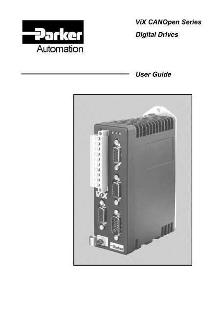
<strong>ViX</strong> <strong>CANOpen</strong> <strong>Series</strong><br />
<strong>Digital</strong> <strong>Drives</strong><br />
<strong>User</strong> <strong>Gui<strong>de</strong></strong>
Part No: 1600.330.02, June 2005<br />
<strong>ViX</strong>250CE, <strong>ViX</strong>500CE, <strong>ViX</strong>250CM,<br />
<strong>ViX</strong>500CM, <strong>ViX</strong>250CH & <strong>ViX</strong>500CH<br />
CANopen<br />
<strong>User</strong> <strong>Gui<strong>de</strong></strong>
IMPORTANT INFORMATION FOR<br />
USERS<br />
Installation and Operation of Motion Control Equipment<br />
It is important that motion control equipment is installed and operated in such a way that all applicable safety<br />
requirements are met. It is your responsibility as an installer to ensure that you i<strong>de</strong>ntify the relevant safety<br />
standards and comply with them; failure to do so may result in damage to equipment and personal injury. In<br />
particular, you should study the contents of this user gui<strong>de</strong> carefully before installing or operating the equipment.<br />
The installation, set-up, test and maintenance procedures given in this <strong>User</strong> <strong>Gui<strong>de</strong></strong> should only be carried out by<br />
competent personnel trained in the installation of electronic equipment. Such personnel should be aware of the<br />
potential electrical and mechanical hazards associated with mains-powered motion control equipment - please<br />
see the safety warning below. The individual or group having overall responsibility for this equipment must<br />
ensure that operators are a<strong>de</strong>quately trained.<br />
Un<strong>de</strong>r no circumstances will the suppliers of the equipment be liable for any inci<strong>de</strong>ntal, consequential or special<br />
damages of any kind whatsoever, including but not limited to lost profits arising from or in any way connected<br />
with the use of the equipment or this user gui<strong>de</strong>.<br />
High-performance motion control equipment is capable of producing rapid movement and very high forces.<br />
Unexpected motion may occur especially during the <strong>de</strong>velopment of controller programs. KEEP WELL CLEAR<br />
of any machinery driven by stepper or servo motors. Never touch any part of the equipment while it is in<br />
operation.<br />
This product is sold as a motion control component to be installed in a complete system using good engineering<br />
practice. Care must be taken to ensure that the product is installed and used in a safe manner according to local<br />
safety laws and regulations. In particular, the product must be enclosed such that no part is accessible while<br />
power may be applied.<br />
If the equipment is used in any manner that does not conform to the instructions given in this user gui<strong>de</strong>, then the<br />
protection provi<strong>de</strong>d by the equipment may be impaired.<br />
The information in this user gui<strong>de</strong>, including any apparatus, methods, techniques, and concepts <strong>de</strong>scribed<br />
herein, are the proprietary property of Parker EME or its licensors, and may not be copied, disclosed, or used for<br />
any purpose not expressly authorised by the owner thereof.<br />
Since Parker EME constantly strives to improve all of its products, we reserve the right to modify equipment and<br />
user gui<strong>de</strong>s without prior notice. No part of this user gui<strong>de</strong> may be reproduced in any form without the prior<br />
consent of Parker EME.<br />
© Electromechanical Division of Parker Hannifin plc, 2005<br />
– All Rights Reserved –
Parker Hannifin plc<br />
Electromechanical Automation<br />
Arena Buisness Centre, Holy Rood Close,<br />
Poole, Dorset. BH17 7BA UK<br />
Tel: +44 (0)1202 606300<br />
Fax: +44 (0)1202 606301<br />
Website : www.parker-eme.com<br />
e-mail : sales.digiplan@parker.com<br />
Parker Hannifin S. p. A<br />
Electromechanical Automation<br />
Via Gounod 1<br />
I-20092 Cinisello Balsamo (MI), Italy<br />
Tel: +39 0266012459<br />
Fax: +39 0266012808<br />
Website : www.parker-eme.com<br />
e-mail : sales.sbc@parker.com<br />
Contact Addresses<br />
Parker Hannifin GmbH<br />
Electromechanical Automation<br />
Robert-Bosch-Str. 22<br />
D-77656 Offenburg, Germany<br />
Tel: +49 (0)781 509-0<br />
Fax: +49 (0)781 509-98176<br />
Website : www.parker-eme.com<br />
e-mail : sales.hauser@parker.com<br />
Parker Hannifin Corporation<br />
Compumotor Division<br />
5500 Business Park Drive, Suite D<br />
Rohnert Park<br />
CA 94928, USA<br />
Tel: +1 (800) 358-9070<br />
Fax: +1 (707) 584-3793<br />
FaxBack System: (800) 936-6939<br />
e-mail: CMR_help@parker.com<br />
Website: www.compumotor.com
VIX CANopen USER GUIDE 1<br />
Contents<br />
1. Introduction .............................................................................................................. 2<br />
2. Software Requirements ........................................................................................... 3<br />
3. External I/O Modules ............................................................................................... 7<br />
4. Object Types............................................................................................................ 10<br />
5. Object Library Communication Objects DS301 V3.0 ............................................... 27<br />
Defined Device Profile Objects DS402 V1.1................................................. 60<br />
7. State Machine.......................................................................................................... 75<br />
Appendix 1 - ASCII Table ............................................................................................. 75<br />
Appendix 2 - CIA DS-301 State Diagram...................................................................... 76<br />
Appendix 3 - TxPDO and RxPDO Transmission Types................................................ 77<br />
Appendix 4 - Further Information on External I/O ......................................................... 78<br />
INDEX........................................................................................................................... 76<br />
Customer Feedback...................................................................................................... 83<br />
<strong>User</strong> <strong>Gui<strong>de</strong></strong> Change Summary<br />
This user gui<strong>de</strong>, version 1600.330.02, is the second version of the <strong>ViX</strong> CANopen <strong>User</strong> <strong>Gui<strong>de</strong></strong>.<br />
It should be noted that there has been extensive modifications by the applications team at<br />
Parker EME. So much so that the standard vertical line used formerly to indicate changes<br />
has been omitted. It is hoped that the rea<strong>de</strong>r will not compare this manual to the previous<br />
version.<br />
Associated Documentation<br />
CIA Draft Standard 301 Version 3.0<br />
CIA Draft Standard Proposal 402 Version 1.1<br />
Hauser COMPAX-M/S Bus-Option: CANopen
VIX CANopen USER GUIDE 2<br />
<strong>User</strong> <strong>Gui<strong>de</strong></strong> Assumptions<br />
1. Introduction<br />
This user gui<strong>de</strong> assumes you have a working knowledge of CANopen Fieldbus Protocol and<br />
you are familiar with the programming and operation of motion control equipment. The gui<strong>de</strong><br />
is inten<strong>de</strong>d as a reference only.<br />
Structure of the <strong>User</strong> <strong>Gui<strong>de</strong></strong><br />
The gui<strong>de</strong> is presented in six sections, summarised below:<br />
Section 1: Introduction<br />
This section, which introduces you to the structure and scope of CANopen used with<br />
Parker <strong>ViX</strong> drives.<br />
Section 2: Software Requirements<br />
Provi<strong>de</strong>s an introduction to CANopen as implemented within the <strong>ViX</strong> drive.<br />
Section 3: External I/O Modules<br />
Describes the use of I/O modules for use on the <strong>CANOpen</strong> fieldbus.<br />
Section 4: Object Types<br />
Describes the type of Data Object used in CANopen. This section inclu<strong>de</strong>s SDO and<br />
PDO <strong>de</strong>finitions combined with configuration and mapping parameters.<br />
Section 5: Object Library<br />
Describes the various forms of Object that are used. These are sub-divi<strong>de</strong>d into the<br />
following types:<br />
Communication objects: 0x1000 to 0x1A01<br />
Manufacturer specific objects: 0x2004 to 0x21A7<br />
Device Profile objects: 0x603F to 0x6504<br />
Section 6: State Machine<br />
The state diagram for CANopen used with Parker <strong>ViX</strong> drives.<br />
Appendices<br />
Appendix 1 contains an ASCII table. This is for the users reference. There are several<br />
objects that return ASCII strings and it has been inclu<strong>de</strong>d to help.<br />
Appendix 2 contains the DS-301 state diagram, again this is used for user reference.<br />
Appendix 3 TxPDO and RxPDO transmission types. This is inclu<strong>de</strong>d to show the user<br />
the differences in transmission types and the associated <strong>ViX</strong> no<strong>de</strong> behaviour.<br />
In<strong>de</strong>x<br />
Customer Feedback
VIX CANopen USER GUIDE 3<br />
Overview<br />
2. Software Requirements<br />
The CANopen Fieldbus is <strong>de</strong>signed for the motion and control market. The fast data rates<br />
and data formatting make it i<strong>de</strong>al for closing low bandwidth control loops with remote<br />
feedback <strong>de</strong>vices. It can support up to 127 no<strong>de</strong>s at up to 500metres distance. Baud rates<br />
range from 20kHz up to 1MHz. Each message can consist of up to 8 bytes of information.<br />
The communications objects for setting the COB-ID, SDOs and PDOs are <strong>de</strong>scribed in the<br />
CIA draft standard 301.<br />
The standard for the <strong>de</strong>vice profile (DSP-402) has been followed at the application level for<br />
configuring the mo<strong>de</strong>s of operation and various other commands where applicable.<br />
In or<strong>de</strong>r to satisfy the functionality of <strong>ViX</strong> stepper and servo products, a set of manufacturer<br />
specific objects have been implemented. These objects allow further drive profile<br />
configuration and allow the use of the specific mo<strong>de</strong>s of operation.<br />
Scope of CAN Bus Control<br />
The objects and their implementation are <strong>de</strong>scribed later in this gui<strong>de</strong>. Further <strong>de</strong>tails are<br />
also given of the software operation and flow. It may be worth consi<strong>de</strong>ring at this point some<br />
of the system limitations for those not needing to know any more than the basics to get a<br />
system running.<br />
The objects do not provi<strong>de</strong> facility for <strong>de</strong>fining labels or some of the higher level report<br />
facilities. The intention is that the drive is pre-programmed with labels and sequences using<br />
EASI-V and the RS232 serial port. This configuration can be saved in each unit prior to being<br />
incorporated into a FieldBus system. A facility is provi<strong>de</strong>d to send commands and data over<br />
the CANopen protocol in ASCII format (object 0x2005). This will only accept one command<br />
per message. The RS232 port should only be used as a maintenance port. The operation of<br />
the software cannot be guaranteed if both the RS232 and CANopen ports are used at the<br />
same time.
VIX CANopen USER GUIDE 4<br />
The CanOpen implementation makes use of an object dictionary that is immediately updated<br />
on a data write access. This maintains the high data transfer rates. The interface software<br />
tokenises the data and places it in a buffer to await execution. The buffer is accessed using<br />
the FIFO principle. As a result of this, an actual write to a parameter such as acceleration<br />
may update the object dictionary immediately but the actual value change may not take place<br />
in the application for several milliseconds, <strong>de</strong>pending on what is already in the buffer. The<br />
minimum time for update would be one millisecond regardless of any impending token in the<br />
buffer.<br />
The data read, however, is taken directly from the application variable. The read gives an<br />
immediate indication of the currently programmed value. This may cause some confusion,<br />
as the parameter may be loa<strong>de</strong>d with one value but, because the buffer is still executing<br />
previous commands, may read back a different value. To be sure that the buffer is clear it is<br />
advisable to read the system status first.<br />
Software Settings<br />
Four parameters relevant to the CanOpen protocol are initiated and saved via the RS232<br />
port. The parameters No<strong>de</strong>-ID, Baud rate, Protocol and Control are configured using ASCII<br />
or CanOpen commands and then saved. The settings are then automatically loa<strong>de</strong>d on the<br />
next power cycle.<br />
Parameter System Variable Range Comments Effective From<br />
No<strong>de</strong> ID FN 1 ….127 Default is 99 Power up<br />
Baudrate FB 0 ….1000 See table (below) Power up<br />
Protocol FP 0 ….255 See table (below) Power up<br />
Control FC 0 ….255 See table (below) Power up<br />
The address of the no<strong>de</strong> can be specified as different to the controller address but must be<br />
unique on the Can bus.<br />
The no<strong>de</strong> address can be configured via the RS232 ASCII link by entering the command:<br />
nW(FN,x)<br />
Where n is the axis (drive address) x is the required CanOpen no<strong>de</strong> address<br />
The parameter can be checked by reading back the data, that is: nR(FN).<br />
These variables are also accessible over CanOpen via object 0x2008 and the relevant subin<strong>de</strong>x.<br />
Care must be taken when using these variables as wrong settings may cause the<br />
CanOpen link to fail.
VIX CANopen USER GUIDE 5<br />
FieldBus No<strong>de</strong> ID (FN)<br />
The <strong>de</strong>fault no<strong>de</strong> ID is 99. The No<strong>de</strong> ID can be set via RS232 this is done by using the<br />
following command:<br />
nW(FN,X)<br />
Where n is the axis (drive address), X is the no<strong>de</strong> address 1 - 127<br />
It can be set so that the CAN no<strong>de</strong> address automatically takes the axis address by setting<br />
the fieldbus control (see below). After a change of value of No<strong>de</strong> ID a SAVE (1SV) must be<br />
executed and power cycled to make the new data valid.<br />
FieldBus Baud Rate (FB)<br />
The parameters for baud rate are limited to the following settings:<br />
Parameter Value 20 50 100 125 250 500 800 1000<br />
Selected Baud Rate 20000 50000 100000 125000 250000 500000 800000 1000000<br />
The required baud rate for CanOpen can be configured via the RS232 ASCII link by entering<br />
the command:<br />
nW(FB,x)<br />
Where n is the axis (drive address), x is the parameter value for the required baud rate<br />
shown above.<br />
The parameter can be checked by reading back the data i.e., nR(FB).<br />
Both of the above set-up parameters can be <strong>de</strong>fined over CanOpen by using the object<br />
0x2008 (Variable Configuration) with the appropriate sub-in<strong>de</strong>x. The revised values will not<br />
become active until the controller has been reset.<br />
Fieldbus Protocol (FP)<br />
This variable is used for setting fieldbus communication options and has currently only one<br />
parameter. Bit 1 is set to indicate that when no<strong>de</strong> guarding is selected, a message is<br />
displayed over RS232 to indicate a change in status of the no<strong>de</strong> guarding. This is relevant to<br />
the port implementation of no<strong>de</strong>-guarding only.
VIX CANopen USER GUIDE 6<br />
Fieldbus Control (Variable FC)<br />
The options for functionality selected using Fieldbus Control are as listed below:<br />
MSB LSB<br />
7 6 5 4 3 2 1 0<br />
State Machine and State Machine over-ri<strong>de</strong><br />
Access to motion control parameters, or any associated parameter, must have the <strong>de</strong>vice<br />
state machine set to operation-enabled before being used. Example parameters are velocity<br />
and acceleration. Less obvious parameters are those to do with running labels as these may<br />
command motion within their routines.<br />
The CanOpen specification <strong>de</strong>fines a state machine to achieve operational state to allow the<br />
motion control parameters. Bit 5 of the FC (i.e. FC = 16) will set the state machine to<br />
Operational mo<strong>de</strong> immediately.<br />
Set State to Operational<br />
The CanOpen specification <strong>de</strong>fines a second state machine for the type of message that will<br />
be accepted as valid.<br />
State/Service SDO PDO EMCY TIME SYNC NMT Error<br />
Control<br />
Boot Up<br />
Initialisation - - - - - - - X<br />
Stopped - - - - - X X -<br />
Pre-Operational X - X X X X X -<br />
Operational X X X X X X X -<br />
For PDOs to be active the state machine must be Operational. With Bit 5 of the Fieldbus<br />
Control set the internal state machine will be set to Operational and will make PDOs valid<br />
without the need for a master axis to send an NMT message.<br />
Use Device Address as No<strong>de</strong> ID<br />
Check to set state machine to Operational (FC = 1)<br />
Reserved<br />
Reserved<br />
Reserved<br />
Set state to operational (FC = 16)<br />
Use <strong>de</strong>vice address for No<strong>de</strong>_ID (FC = 32)<br />
Reserved<br />
Enable FMON<br />
When this bit is set the saved No<strong>de</strong> ID is over-written and the <strong>de</strong>vice address is used as the<br />
No<strong>de</strong> ID. The parameter is only valid on power-up or after a reset.
VIX CANopen USER GUIDE 7<br />
Overview<br />
3. External I/O Modules 1<br />
Parker has introduced a range of I/O modules for use on the <strong>CANOpen</strong> FieldBUS. The<br />
implementation of <strong>CANOpen</strong> on the <strong>ViX</strong> product range has been enhanced to inclu<strong>de</strong> the<br />
monitor and trigger on condition of external I/O modules. The command structure has been<br />
ma<strong>de</strong> such that the status of the inputs and outputs can be can be accessed through two<br />
new variables IE and OE. To date the FMON command supports up to 32 digital inputs and<br />
32 outputs. Analogue I/O is not yet supported.<br />
This command has been <strong>de</strong>signed with the Parker PIO in mind although so long as the I/O<br />
<strong>de</strong>vice does not send more than 32 bits within its’ TxPDO the <strong>de</strong>vice will be compatible.<br />
The <strong>CANOpen</strong> <strong>ViX</strong> drive has been equipped with a simple NMT capable of setting the<br />
chosen no<strong>de</strong> into the ‘Operational’ state. This can be achieved using the ‘FC’ variable. It is<br />
recommen<strong>de</strong>d that upon completion of a correct FMON command that the user sets the ‘FC’<br />
variable correctly.<br />
With reference to the ‘FC’ command the MSB and LSB should be set to enable and hence<br />
run external <strong>CANOpen</strong> I/O.<br />
1W(FC,129)<br />
On sending this command, save (SV) and reset (Z) the unit. The user will notice that the drive<br />
will then go through the boot sequence, the ‘FB’ LED will flash for 3 seconds and then remain<br />
on. This is confirmation of correct operation of the NMT, the user should also notice that the<br />
I/O ‘RUN’ or ‘STATUS’ LED should stay on.<br />
Configuration<br />
A single command is used to configure the input source.<br />
aFMON(remote_no<strong>de</strong>_ID,remote_inputs,remote_outputs)<br />
where:<br />
a is the axis number of the <strong>ViX</strong> product<br />
remote_no<strong>de</strong>_ID is the no<strong>de</strong> number of the input module.<br />
remote_inputs is the number of expected inputs.<br />
remote_outputs is the number of expected outputs.<br />
The configured parameters must be saved and will become active on the next power cycle.<br />
The range of the inputs are as follows: 8, 16 and 32. It is important this value is either greater<br />
than or equal to the actual number used.<br />
To check the configuration a single command will report the state of both the inputs and<br />
outputs.<br />
1 For the interested user, some more information and FAQ’s can be found in Appendix 4
VIX CANopen USER GUIDE 8<br />
aFMON<br />
where:<br />
a is the axis number of the <strong>ViX</strong> product<br />
An example using this is shown below:<br />
1FMON<br />
*FMON(3,16,16)<br />
Reporting the received data for each input is prompted with a single command.<br />
aIS1<br />
where:<br />
a is the axis number of the <strong>ViX</strong> product<br />
The value is reported as a bit pattern, an example response is shown below, where input 1 is<br />
the first. It can be seen that the input 8 is set on.<br />
1IS1<br />
*0000_0001_0000_0000_0000_0000_0000_0000<br />
If the module number is omitted then the ‘IS’ command will revert to its RS232 state and<br />
report the <strong>ViX</strong> product input status as a bit pattern. It should be noted that to check each<br />
bank of the external inputs then the ‘IE’ command should be used, please refer to the section<br />
‘Decision Making on External I/O’.<br />
Reporting and setting the current output status is also covered by a single command.<br />
aOE<br />
where:<br />
a is the axis number of the <strong>ViX</strong> product<br />
Unlike the ‘IS’ command the information is reported back in a hexa<strong>de</strong>cimal format. The<br />
example below shows how to set the last four bits i.e. the first four outputs of the CAN I/O<br />
and report back the current output status.<br />
1OE(000F)<br />
1OE<br />
*0x0000000F<br />
It should be noted that the CAN outputs function in a similar way to the ‘O’ command. This<br />
command is immediate and not saveable thus when the drive is reset or the 24V logic lost the<br />
outputs are set to zero.
VIX CANopen USER GUIDE 9<br />
Decision Making on External I/O<br />
It is possible to use the ‘IF’ and the ‘TR’ commands with the external I/O to affect program<br />
flow. This can only be done as a bit mask for banks of 8 bits at once and applies to both the<br />
external inputs ‘IE’ and external outputs ‘OE’.<br />
Using a Mask (Bit Pattern)<br />
The format of the command is no different to the standard ‘IF’ or ‘TR’ test. The structure of<br />
the command is:<br />
aTR(IEn,cond,val) or aIF(IEn,cond,val)<br />
aTR(OEn,cond,val) or aIF(OEn,cond,val)<br />
where;<br />
a is the axis number of the <strong>ViX</strong> product<br />
n is the bank number of the 8-bit external I/O to be addressed, this can be<br />
IE1 .. 4 or OE1 .. 4.<br />
cond is the condition to be executed to the following value for the next line to<br />
execute, this condition can be = or .<br />
val is entered as an 8 bit mask (binary) for the comparison, bits can be<br />
<strong>de</strong>noted in the mask as 0, 1 or X ‘don’t care’.<br />
Example: 1TR(IE1,=,XXXXXXX1) or 1IF(IE2,=,11XX0XX1)<br />
1TR(OE1,=,1XX0XXX1) or 1IF(OE3,=,100X0XXX)
VIX CANopen USER GUIDE 10<br />
Addressing<br />
4. Object Types<br />
Every object type is accessed through a Communication OBject IDentifier (COB-ID). The<br />
COB-ID is ma<strong>de</strong> up from a function co<strong>de</strong> representing the object type followed by a seven-bit<br />
<strong>de</strong>vice address.<br />
Communication Object I<strong>de</strong>ntifier (COB-ID)<br />
Function Co<strong>de</strong> Device Address (No<strong>de</strong> ID): 1 ... 127<br />
The COB-ID also <strong>de</strong>fines the priority of the message with the highest priority going to the<br />
lowest COB-ID. The following table gives an overview of the object availability.<br />
Object<br />
Type<br />
Function<br />
Co<strong>de</strong> (Bin)<br />
COB-ID<br />
(Hex)<br />
Broadcast Objects<br />
Defined In<strong>de</strong>x<br />
(Hex)<br />
Description<br />
NMT 0000 0x000 - Network Management<br />
SYNC 0001 128 (0x080) 0x1005 COB-ID of the SYNC<br />
object<br />
TIME 0010 256 (0x100) 0x1012<br />
EMCY 0001 129 – 255<br />
Peer to Peer Objects<br />
(0x081 - 0x0FF)<br />
TxPDO1 0011 385 - 511<br />
(0x181 - 0x1FF)<br />
TxPDO2 0101 641 - 767<br />
0x281 - 0x2FF<br />
RxPDO1 0100 513 - 639<br />
0x201 - 0x27F<br />
RxPDO2 0110 769 - 895<br />
0x301 - 0x37F<br />
TxSDO1 1011 1409 - 1535<br />
0x581 - 0x5FF<br />
RxSDO1 1100 1537 - 1663<br />
0x601 - 0x67F<br />
NMT Error Control 1110 1793 - 1919<br />
0x701 - 0x77F<br />
0x1014 Emergency (fault)<br />
0x1800 Allocated In<strong>de</strong>x 1A00h, 1 st<br />
Transmit PDO<br />
0x1801 Allocated In<strong>de</strong>x 1A01h, 2 nd<br />
Transmit PDO<br />
0x1400 Allocated In<strong>de</strong>x 1600h, 1 st<br />
Receive PDO<br />
0x1401 Allocated In<strong>de</strong>x 1601h, 2 nd<br />
Receive PDO<br />
0x1200 Transmit Service Data<br />
Object 1<br />
0x1200 Receive Service Data<br />
Object 1<br />
0x100E No<strong>de</strong> Guarding checking<br />
Bus integrity
VIX CANopen USER GUIDE 11<br />
Service Data Messages<br />
The Parker EME implementation of CANopen supports a single transmit Service Data Object<br />
(TxSDO1) and a single receive SDO (RxSDO1). The configuration and addressing are<br />
shown below.<br />
SDO Configuration<br />
0x1200 SDO Configuration Object Details<br />
In<strong>de</strong>x Sub<br />
Name Object Elements Attribute PDO<br />
In<strong>de</strong>x<br />
Co<strong>de</strong><br />
Mapping<br />
0x1200 00 Server SDO Parameter Array 3 RO No<br />
0x1200.00 SDO Configuration Number of Entries<br />
In<strong>de</strong>x Sub Name Type Attribute Object Values<br />
In<strong>de</strong>x<br />
Default Minimum Maximum<br />
0x1200 00 Number of<br />
Entries<br />
Unsigned8 RO 0x02 0x02 0x03<br />
0x1200.01 SDO Configuration RxSDO1 COB ID<br />
In<strong>de</strong>x Sub Name Type Attribute<br />
Object Values<br />
In<strong>de</strong>x<br />
Default Minimum Maximum<br />
0x1200 01 RxSDO1 Unsigned32 RO 0x600 +<br />
No<strong>de</strong> ID<br />
0x601 0x67F<br />
This object specifies the COB ID of the SDO parameter. This is calculated automatically by<br />
the drive. The direction of this SDO is: Bus Master <strong>ViX</strong> No<strong>de</strong>.<br />
0x1200.02 SDO Configuration TxSDO1 COB ID<br />
In<strong>de</strong>x Sub Name Type Attribute<br />
Object Values<br />
In<strong>de</strong>x<br />
Default Minimum Maximum<br />
0x1200 02 TxSDO1 Unsigned32 RO 0x580 +<br />
No<strong>de</strong> ID<br />
0x581 0x5FF<br />
This object specifies the COB ID of the SDO parameter. This is calculated automatically by<br />
the drive. The direction of this SDO is: <strong>ViX</strong> No<strong>de</strong> Bus Master.<br />
These data messages are used for read and write access to all entries of the object<br />
dictionary. Messages of this type are relatively slow and where possible the use of PDOs is<br />
suggested. For example the 0x2004 and 0x2007 would be i<strong>de</strong>al objects to be sent by SDO.
VIX CANopen USER GUIDE 12<br />
Process Data Messages (PDO)<br />
The Parker EME implementation of CANopen supports up to two transmit Process Data<br />
Objects (TxPDO) and two receive PDOs (RxPDO). PDOs are sent with no protocol overhead<br />
and are therefore very fast. They are i<strong>de</strong>al for real-time data to be transferred. They can be<br />
programmed to be cyclic or acyclic. They can be configured by using SDOs.<br />
Example PDO Mapping RxPDO1<br />
From the ‘Software Requirements – Overview’ section the user will remember that the <strong>ViX</strong><br />
can support 8 data bytes of information mapped per PDO. To aid un<strong>de</strong>rstanding an example<br />
has been written below.<br />
We already have a <strong>de</strong>fault mapping for the TxPDO (0x1A00) first entry we will use this and<br />
two others in this example.<br />
In<strong>de</strong>x Sub<br />
In<strong>de</strong>x<br />
Object PDO Entry PDO Length Byte Count<br />
0x6041 00 Status Word 60 41 00 10 00 00 2 bytes<br />
0x6040 00 Control Word 60 40 00 10 00 00 2 bytes<br />
0x6064 00 Position Actual 60 64 00 20 00 00 00 00 4 bytes<br />
The correct operation to perform this mapping is shown in the flow diagram below.<br />
When the NMT is used to start the no<strong>de</strong>, it can be seen that the packet sent is 8 bytes long.
VIX CANopen USER GUIDE 13<br />
RxPDO1 Configuration (Bus Master <strong>ViX</strong> No<strong>de</strong>)<br />
0x1400 RxPDO1 Configuration Object Details<br />
In<strong>de</strong>x Sub<br />
Name Object Elements Attribute PDO<br />
In<strong>de</strong>x<br />
Co<strong>de</strong><br />
Mapping<br />
0x1400 00 RxPDO1 Parameter Array 4 - No<br />
0x1400.00 RxPDO1 Configuration Number of Entries<br />
In<strong>de</strong>x Sub Name Type Attribute<br />
Object Values<br />
In<strong>de</strong>x<br />
Default Minimum Maximum<br />
0x1400 00 Number of<br />
Entries<br />
Unsigned8 RO 0x03 0x02 0x03<br />
0x1400.01 RxPDO1 Configuration RxPDO1 COB ID<br />
In<strong>de</strong>x Sub Name Type Attribute<br />
Object Values<br />
In<strong>de</strong>x<br />
Default Minimum Maximum<br />
0x1400 01 COB-ID of Unsigned32 RW 0x200 + 0x201 0x27F<br />
RxPDO1<br />
No<strong>de</strong> ID<br />
0x1400.02 RxPDO1 Configuration Transmission Type<br />
In<strong>de</strong>x Sub Name Type Attribute<br />
Object Values<br />
In<strong>de</strong>x<br />
Default Minimum Maximum<br />
0x1400 02 Transmission<br />
Type<br />
Unsigned8 RW 0xFE 0x00 0xFF<br />
For further information on the transmission types, please refer to Appendix 3.<br />
0x1400.03 RxPDO1 Configuration Inhibit Time<br />
In<strong>de</strong>x Sub Name Type Attribute<br />
Object Values<br />
In<strong>de</strong>x<br />
Default Minimum Maximum<br />
0x1400 03 Inhibit Time Unsigned16 RW 0x03E8 0x0000 0xFFFF<br />
It is important to remember that this value is specified in units where: 1 unit = 100μs.
VIX CANopen USER GUIDE 14<br />
RxPDO2 Configuration (Bus Master <strong>ViX</strong> No<strong>de</strong>)<br />
0x1401 RxPDO2 Configuration Object Details<br />
In<strong>de</strong>x Sub<br />
Name Object Elements Attribute PDO<br />
In<strong>de</strong>x<br />
Co<strong>de</strong><br />
Mapping<br />
0x1401 00 RxPDO2 Parameter Array 4 - No<br />
0x1401.00 RxPDO2 Configuration Number of Entries<br />
In<strong>de</strong>x Sub Name Type Attribute<br />
Object Values<br />
In<strong>de</strong>x<br />
Default Minimum Maximum<br />
0x1401 00 Number of<br />
Entries<br />
Unsigned8 RO 0x03 0x02 0x03<br />
0x1401.01 RxPDO2 Configuration RxPDO2 COB ID<br />
In<strong>de</strong>x Sub Name Type Attribute<br />
Object Values<br />
In<strong>de</strong>x<br />
Default Minimum Maximum<br />
0x1401 01 Number of Unsigned32 RW 0x300 + 0x301 0x37F<br />
Entries<br />
No<strong>de</strong> ID<br />
0x1401.02 RxPDO2 Configuration Transmission Type<br />
In<strong>de</strong>x Sub Name Type Attribute<br />
Object Values<br />
In<strong>de</strong>x<br />
Default Minimum Maximum<br />
0x1401 02 Transmission<br />
Type<br />
Unsigned8 RW 0xFE 0x00 0xFF<br />
For further information on the transmission types, please refer to Appendix 3.<br />
0x1401.03 RxPDO2 Configuration Inhibit Time<br />
In<strong>de</strong>x Sub Name Type Attribute<br />
Object Values<br />
In<strong>de</strong>x<br />
Default Minimum Maximum<br />
0x1401 02 Inhibit Time Unsigned16 RW 0x03E8 0x0000 0xFFFF<br />
It is important to remember that this value is specified in units where: 1 unit = 100μs.
VIX CANopen USER GUIDE 15<br />
RxPDO1 Mapping Parameter<br />
0x1600 RxPDO1 Mapping Object Details<br />
In<strong>de</strong>x Sub<br />
Name Object Elements Attribute PDO<br />
In<strong>de</strong>x<br />
Co<strong>de</strong><br />
Mapping<br />
0x1600 00 RxPDO1 Parameter Array 5 - No<br />
0x1600.00 RxPDO1 Mapping Number of Entries<br />
In<strong>de</strong>x Sub Name Type Attribute<br />
Object Values<br />
In<strong>de</strong>x<br />
Default Minimum Maximum<br />
0x1600 00 Number of<br />
Entries<br />
Unsigned8 RW 0x02 0x00 0x04<br />
0x1600.01 RxPDO1 Mapping PDO Mapping Entry 1<br />
In<strong>de</strong>x Sub<br />
In<strong>de</strong>x<br />
0x1600 01<br />
Name Type Attribute<br />
PDO Mapping<br />
Entry<br />
Default<br />
Object Values<br />
Minimum Maximum<br />
Unsigned32 RW 0x60400010 0x00000000 0xFFFFFFFF<br />
This PDO has a <strong>de</strong>fault mapping of 0x6040 the <strong>ViX</strong> Control Word.<br />
0x1600.02 RxPDO1 Mapping PDO Mapping Entry 2<br />
In<strong>de</strong>x Sub<br />
In<strong>de</strong>x<br />
0x1600 02<br />
Name Type Attribute<br />
PDO Mapping<br />
Entry<br />
Default<br />
Object Values<br />
Minimum Maximum<br />
Unsigned32 RW 0x60640020 0x00000000 0xFFFFFFFF<br />
This PDO has a <strong>de</strong>fault mapping of 0x6064 the <strong>ViX</strong> Position Actual value.<br />
0x1600.03 RxPDO1 Mapping PDO Mapping Entry 3<br />
In<strong>de</strong>x Sub<br />
In<strong>de</strong>x<br />
0x1600 03<br />
Name Type Attribute<br />
PDO Mapping<br />
Entry<br />
Default<br />
Object Values<br />
Minimum Maximum<br />
Unsigned32 RW 0x00000000 0x00000000 0xFFFFFFFF<br />
0x1600.04 RxPDO1 Mapping PDO Mapping Entry 4<br />
In<strong>de</strong>x Sub<br />
In<strong>de</strong>x<br />
0x1600 04<br />
Name Type Attribute<br />
PDO Mapping<br />
Entry<br />
Default<br />
Object Values<br />
Minimum Maximum<br />
Unsigned32 RW 0x00000000 0x00000000 0xFFFFFFFF
VIX CANopen USER GUIDE 16<br />
RxPDO2 Mapping Parameter<br />
0x1601 RxPDO2 Mapping Object Details<br />
In<strong>de</strong>x Sub<br />
Name Object Elements Attribute PDO<br />
In<strong>de</strong>x<br />
Co<strong>de</strong><br />
Mapping<br />
0x1601 00 RxPDO2 Parameter Array 5 - No<br />
0x1601.00 RxPDO2 Mapping Number of Entries<br />
In<strong>de</strong>x Sub Name Type Attribute<br />
Object Values<br />
In<strong>de</strong>x<br />
Default Minimum Maximum<br />
0x1601 00 Number of<br />
Entries<br />
Unsigned8 RW 0x02 0x00 0x04<br />
0x1601.02 RxPDO2 Mapping PDO Mapping Entry 1<br />
In<strong>de</strong>x Sub<br />
In<strong>de</strong>x<br />
0x1601 01<br />
Name Type Attribute<br />
PDO Mapping<br />
Entry<br />
Default<br />
Object Values<br />
Minimum Maximum<br />
Unsigned32 RW 0x00000000 0x00000000 0xFFFFFFFF<br />
0x1601.02 RxPDO2 Mapping PDO Mapping Entry 2<br />
In<strong>de</strong>x Sub<br />
In<strong>de</strong>x<br />
0x1601 02<br />
Name Type Attribute<br />
PDO Mapping<br />
Entry<br />
Default<br />
Object Values<br />
Minimum Maximum<br />
Unsigned32 RW 0x00000000 0x00000000 0xFFFFFFFF<br />
0x1601.03 RxPDO2 Mapping PDO Mapping Entry 3<br />
In<strong>de</strong>x Sub<br />
In<strong>de</strong>x<br />
0x1601 03<br />
Name Type Attribute<br />
PDO Mapping<br />
Entry<br />
Default<br />
Object Values<br />
Minimum Maximum<br />
Unsigned32 RW 0x00000000 0x00000000 0xFFFFFFFF<br />
0x1601.04 RxPDO2 Mapping PDO Mapping Entry 4<br />
In<strong>de</strong>x Sub<br />
In<strong>de</strong>x<br />
0x1601 04<br />
Name Type Attribute<br />
PDO Mapping<br />
Entry<br />
Default<br />
Object Values<br />
Minimum Maximum<br />
Unsigned32 RW 0x00000000 0x00000000 0xFFFFFFFF
VIX CANopen USER GUIDE 17<br />
Objects Available for RxPDO Mapping<br />
In<strong>de</strong>x<br />
Sub<br />
In<strong>de</strong>x<br />
Object<br />
System<br />
Variable<br />
Attributes<br />
Byte<br />
Count<br />
PDO Entry<br />
0x2004 00 Control - WO 2 20 04 00 10<br />
0x2050 00 Incremental Position PI RW 4 20 50 00 20<br />
0x2051 00 Position Error PE RW 4 20 51 00 20<br />
0x2052 00 Position Target PT RW 4 20 52 00 20<br />
0x6040 00 Control Word - RW 2 60 40 00 10<br />
0x6064 00 Position Actual PA RW 4 60 64 00 20<br />
0x607A 00 Target Position D RW 4 60 7A 00 20<br />
0x6081 00 Profile Velocity V RW 4 60 81 00 20<br />
0x6300 00 Output Word O RW 2 63 00 00 10
VIX CANopen USER GUIDE 18<br />
TxPDO1 Configuration (<strong>ViX</strong> No<strong>de</strong> Bus Master)<br />
0x1800 TxPDO1 Configuration Object Details<br />
In<strong>de</strong>x Sub<br />
Name Object Elements Attribute PDO<br />
In<strong>de</strong>x<br />
Co<strong>de</strong><br />
Mapping<br />
0x1800 00 TxPDO1 Parameter Array 6 - No<br />
0x1800.00 TxPDO1 Configuration Number of Entries<br />
In<strong>de</strong>x Sub Name Type Attribute<br />
Object Values<br />
In<strong>de</strong>x<br />
Default Minimum Maximum<br />
0x1800 00 Number of<br />
Entries<br />
Unsigned8 RO 0x05 0x02 0x05<br />
0x1800.01 TxPDO1 Configuration TxPDO1 COB ID<br />
In<strong>de</strong>x Sub Name Type Attribute<br />
Object Values<br />
In<strong>de</strong>x<br />
Default Minimum Maximum<br />
0x1800 01 COB-ID of Unsigned32 RW 0x180 + 0x181 0x1FF<br />
TxPDO1<br />
No<strong>de</strong> ID<br />
0x1800.02 TxPDO1 Configuration Transmission Type<br />
In<strong>de</strong>x Sub Name Type Attribute<br />
Object Values<br />
In<strong>de</strong>x<br />
Default Minimum Maximum<br />
0x1800 02 Transmission<br />
Type<br />
Unsigned8 RW 0xFE 0x00 0xFF<br />
For further information on the transmission types, please refer to Appendix 3.<br />
0x1800.03 TxPDO1 Configuration Inhibit Time<br />
In<strong>de</strong>x Sub Name Type Attribute<br />
Object Values<br />
In<strong>de</strong>x<br />
Default Minimum Maximum<br />
0x1800 03 Inhibit Time Unsigned16 RW 0x03E8 0x0000 0xFFFF<br />
It is important to remember that this value is specified in units where: 1 unit = 100μs.
VIX CANopen USER GUIDE 19<br />
0x1800.04 TxPDO1 Configuration Reserved<br />
In<strong>de</strong>x Sub Name Type Attribute<br />
Object Values<br />
In<strong>de</strong>x<br />
Default Minimum Maximum<br />
0x1800 04 Reserved Unsigned8 N/A 0x00 0x00 0xFF<br />
0x1800.05 TxPDO1 Configuration Event Timer<br />
In<strong>de</strong>x Sub Name Type Attribute<br />
Object Values<br />
In<strong>de</strong>x<br />
Default Minimum Maximum<br />
0x1800 05 Event Timer Unsigned16 RW 0x000A 0x0000 0xFFFF<br />
Asynchronous TxPDOs can be transmitted cyclically with the event timer. If its value is<br />
greater than 0, it becomes a millisecond timer. When this is expired, the PDO is transmitted.<br />
Transmission therefore takes place both when an external <strong>de</strong>vice input is altered and when<br />
the event timer is lapsed.
VIX CANopen USER GUIDE 20<br />
TxPDO2 Configuration (<strong>ViX</strong> No<strong>de</strong> Bus Master)<br />
0x1801 TxPDO2 Configuration Object Details<br />
In<strong>de</strong>x Sub<br />
Name Object Elements Attribute PDO<br />
In<strong>de</strong>x<br />
Co<strong>de</strong><br />
Mapping<br />
0x1801 00 TxPDO2 Parameter Array 6 - No<br />
0x1801.00 TxPDO2 Configuration Number of Entries<br />
In<strong>de</strong>x Sub Name Type Attribute<br />
Object Values<br />
In<strong>de</strong>x<br />
Default Minimum Maximum<br />
0x1801 00 Number of<br />
Entries<br />
Unsigned8 RO 0x05 0x02 0x05<br />
0x1801.01 TxPDO2 Configuration TxPDO2 COB ID<br />
In<strong>de</strong>x Sub Name Type Attribute<br />
Object Values<br />
In<strong>de</strong>x<br />
Default Minimum Maximum<br />
0x1801 01 COB-ID of Unsigned32 RW 0x280 + 0x281 0x2FF<br />
TxPDO2<br />
No<strong>de</strong> ID<br />
0x1801.02 TxPDO2 Configuration Transmission Type<br />
In<strong>de</strong>x Sub Name Type Attribute<br />
Object Values<br />
In<strong>de</strong>x<br />
Default Minimum Maximum<br />
0x1801 02 Transmission<br />
Type<br />
Unsigned8 RW 0xFE 0x00 0xFF<br />
For further information on the transmission types, please refer to Appendix 3.<br />
0x1801.03 TxPDO2 Configuration Inhibit Time<br />
In<strong>de</strong>x Sub Name Type Attribute<br />
Object Values<br />
In<strong>de</strong>x<br />
Default Minimum Maximum<br />
0x1801 02 Inhibit Time Unsigned16 RW 0x03E8 0x0000 0xFFFF<br />
It is important to remember that this value is specified in units where: 1 unit = 100μs.
VIX CANopen USER GUIDE 21<br />
0x1801.04 TxPDO2 Configuration Reserved<br />
In<strong>de</strong>x Sub Name Type Attribute<br />
Object Values<br />
In<strong>de</strong>x<br />
Default Minimum Maximum<br />
0x1800 04 Reserved Unsigned8 N/A 0x00 0x00 0xFF<br />
0x1801.05 TxPDO2 Configuration Event Timer<br />
In<strong>de</strong>x Sub Name Type Attribute<br />
Object Values<br />
In<strong>de</strong>x<br />
Default Minimum Maximum<br />
0x1800 05 Event Timer Unsigned16 RW 0x000A 0x0000 0xFFFF<br />
Asynchronous TxPDOs can be transmitted cyclically with the event timer. If its value is<br />
greater than 0, it becomes a millisecond timer. When this is expired, the PDO is transmitted.<br />
Transmission therefore takes place both when an external <strong>de</strong>vice input is altered and when<br />
the event timer is lapsed.
VIX CANopen USER GUIDE 22<br />
TxPDO1 Mapping Parameter<br />
0x1A00 TxPDO1 Mapping Object Details<br />
In<strong>de</strong>x Sub<br />
Name Object Elements Attribute PDO<br />
In<strong>de</strong>x<br />
Co<strong>de</strong><br />
Mapping<br />
0x1A00 00 TxPDO1 Parameter Array 5 - No<br />
0x1A00.00 TxPDO1 Mapping Number of Entries<br />
In<strong>de</strong>x Sub Name Type Attribute<br />
Object Values<br />
In<strong>de</strong>x<br />
Default Minimum Maximum<br />
0x1A00 00 Number of<br />
Entries<br />
Unsigned8 RW 0x02 0x00 0x04<br />
0x1A00.01 TxPDO1 Mapping PDO Mapping Entry 1<br />
In<strong>de</strong>x Sub<br />
In<strong>de</strong>x<br />
0x1A00 01<br />
Name Type Attribute<br />
PDO Mapping<br />
Entry<br />
Default<br />
Object Values<br />
Minimum Maximum<br />
Unsigned32 RW 0x60410010 0x00000000 0xFFFFFFFF<br />
This PDO has a <strong>de</strong>fault mapping of 0x6041 the <strong>ViX</strong> Status Word.<br />
0x1A00.02 TxPDO1 Mapping PDO Mapping Entry 2<br />
In<strong>de</strong>x Sub<br />
In<strong>de</strong>x<br />
0x1A00 02<br />
Name Type Attribute<br />
PDO Mapping<br />
Entry<br />
Default<br />
Object Values<br />
Minimum Maximum<br />
Unsigned32 RW 0x00000000 0x00000000 0xFFFFFFFF<br />
0x1A00.03 TxPDO1 Mapping PDO Mapping Entry 3<br />
In<strong>de</strong>x Sub<br />
In<strong>de</strong>x<br />
0x1A00 03<br />
Name Type Attribute<br />
PDO Mapping<br />
Entry<br />
Default<br />
Object Values<br />
Minimum Maximum<br />
Unsigned32 RW 0x00000000 0x00000000 0xFFFFFFFF<br />
0x1A00.04 TxPDO1 Mapping PDO Mapping Entry 4<br />
In<strong>de</strong>x Sub<br />
In<strong>de</strong>x<br />
0x1A00 04<br />
Name Type Attribute<br />
PDO Mapping<br />
Entry<br />
Default<br />
Object Values<br />
Minimum Maximum<br />
Unsigned32 RW 0x00000000 0x00000000 0xFFFFFFFF
VIX CANopen USER GUIDE 23<br />
TxPDO2 Mapping Parameter<br />
0x1A01 TxPDO2 Mapping Object Details<br />
In<strong>de</strong>x Sub<br />
Name Object Elements Attribute PDO<br />
In<strong>de</strong>x<br />
Co<strong>de</strong><br />
Mapping<br />
0x1A01 00 TxPDO2 Parameter Array 5 - No<br />
0x1A01.00 TxPDO2 Mapping Number of Entries<br />
In<strong>de</strong>x Sub Name Type Attribute<br />
Object Values<br />
In<strong>de</strong>x<br />
Default Minimum Maximum<br />
0x1A01 00 Number of<br />
Entries<br />
Unsigned8 RW 0x00 0x00 0x04<br />
0x1A01.02 TxPDO2 Mapping PDO Mapping Entry 1<br />
In<strong>de</strong>x Sub<br />
In<strong>de</strong>x<br />
0x1A01 01<br />
Name Type Attribute<br />
PDO Mapping<br />
Entry<br />
Default<br />
Object Values<br />
Minimum Maximum<br />
Unsigned32 RW 0x00000000 0x00000000 0xFFFFFFFF<br />
0x1A01.02 TxPDO2 Mapping PDO Mapping Entry 2<br />
In<strong>de</strong>x Sub<br />
In<strong>de</strong>x<br />
0x1A01 02<br />
Name Type Attribute<br />
PDO Mapping<br />
Entry<br />
Default<br />
Object Values<br />
Minimum Maximum<br />
Unsigned32 RW 0x00000000 0x00000000 0xFFFFFFFF<br />
0x1A01.03 TxPDO2 Mapping PDO Mapping Entry 3<br />
In<strong>de</strong>x Sub<br />
In<strong>de</strong>x<br />
0x1A01 03<br />
Name Type Attribute<br />
PDO Mapping<br />
Entry<br />
Default<br />
Object Values<br />
Minimum Maximum<br />
Unsigned32 RW 0x00000000 0x00000000 0xFFFFFFFF<br />
0x1A01.04 TxPDO2 Mapping PDO Mapping Entry 4<br />
In<strong>de</strong>x Sub<br />
In<strong>de</strong>x<br />
0x1A01 04<br />
Name Type Attribute<br />
PDO Mapping<br />
Entry<br />
Default<br />
Object Values<br />
Minimum Maximum<br />
Unsigned32 RW 0x00000000 0x00000000 0xFFFFFFFF
VIX CANopen USER GUIDE 24<br />
Objects Available for Transmit PDO Mapping<br />
In<strong>de</strong>x<br />
Sub<br />
In<strong>de</strong>x<br />
Object<br />
System<br />
Variable Attributes<br />
Byte<br />
Count<br />
PDO Entry<br />
0x2007 01 Analogue Input AI RO 2 20 07 01 10<br />
0x2007 03 In<strong>de</strong>xer Status ST RO 4 20 07 03 10<br />
0x2007 05 Ready / Busy Flag RB RO 1 20 07 05 10<br />
0x2007 06 Position Registration PR RO 4 20 07 06 10<br />
0x2050 00 Incremental Position PI RW 4 20 50 00 20<br />
0x2051 00 Position Error PE RW 4 20 51 00 20<br />
0x2052 00 Position Target PT RW 4 20 52 00 20<br />
0x6040 00 Control Word - RW 2 60 40 00 10<br />
0x6041 00 Status Word ST RO 2 60 41 00 10<br />
0x6064 00 Position Actual PA RO 4 60 64 00 20<br />
0x606C 00 Velocity V RO 4 60 6C 00 20<br />
0x607A 00 Target Position D RW 4 60 7A 00 20<br />
0x6081 00 Profile Velocity V RW 4 60 81 00 20<br />
0x6100 00 Input Word IS RO 2 61 00 00 10<br />
0x6300 00 Output Word O RW 2 63 00 00 10
VIX CANopen USER GUIDE 25
VIX CANopen USER GUIDE 27<br />
Object Table<br />
5. Object Library<br />
Communication Objects (DS-301 V 3.0)<br />
Object Object Name<br />
Sub<br />
In<strong>de</strong>xes<br />
Object Type Attributes<br />
0x1000 Device Type 00 Unsigned32 RO<br />
0x1001 Error Register 00 Unsigned8 RO<br />
0x1003 Pre Defined Error Field 01 Unsigned32 RW<br />
0x1008 Manufacturers Device Name 00 Visible String RO<br />
0x1009 Manufacturers Hardware<br />
Version<br />
00 Visible String RO<br />
0x100A Manufacturers Software Version 00 Visible String RO<br />
0x100C Guard Time 00 Unsigned16 RW<br />
0x100D Life Time Factor 00 Unsigned8 RW<br />
0x1014 COB-ID Emergency Object 00 Unsigned32 RW<br />
0x1018 I<strong>de</strong>ntity Object 01 Unsigned32 RO<br />
0x1200 1 st Server SDO 03 Various RO<br />
0x1400 1 st RxPDO Parameter 03 Various RW<br />
0x1401 2 nd RxPDO Parameter 03 Various RW<br />
0x1600 1 st RxPDO Mapping 04 Various RW<br />
0x1601 2 nd RxPDO Mapping 04 Various RW<br />
0x1800 1 st TxPDO Parameter 05 Various RW<br />
0x1801 2 nd TxPDO Parameter 05 Various RW<br />
0x1A00 1 st TxPDO Mapping 04 Various RW<br />
0x1A01 2 nd TxPDO Mapping 04 Various RW<br />
General Notes<br />
The table (above) shows the Objects that are implemented in <strong>ViX</strong> products configured for<br />
CANopen protocol. The implementation of these objects is based on the Draft Standard of<br />
the Communication Profile DS-301 version 3.0.<br />
0x1000 Device Type<br />
In<strong>de</strong>x Sub-In<strong>de</strong>x Name Type Attribute Default Value<br />
0x1000 00 Device Type Unsigned32 RO 00 02 01 92 – <strong>ViX</strong> Servo Drive<br />
00 04 01 92 – <strong>ViX</strong> Stepper<br />
Drive<br />
The ’01 92’ refers to the <strong>de</strong>vice profile for drives and motion control. This profile number is<br />
402 d. The ’00 02’ and ’00 04’ refer to the additional information that can be specified. In the<br />
case of ’00 02’ this specifies a Servo Drive while ’00 04’ specifies a Stepper Drive.
VIX CANopen USER GUIDE 28<br />
0x1001 Error Register<br />
In<strong>de</strong>x Sub-In<strong>de</strong>x Name Type Attribute Default Value<br />
0x1001 00 Error Register Unsigned8 RO N/A<br />
This register contains internal errors. This register is also part of the emergency message.<br />
Further information as to the layout has been shown below. In the event of an error bit ‘0’ is<br />
always set.<br />
0x1003 Pre-<strong>de</strong>fined Error Field<br />
Bit Meaning<br />
0 General Error<br />
1 Current<br />
2 Voltage<br />
3 Temperature<br />
4 Communication<br />
5 Device Profile Specific<br />
6 Reserved<br />
7 Manufacturer Specific<br />
In<strong>de</strong>x Sub-In<strong>de</strong>x Name Type Attribute Default Value<br />
0x1003 00 Number of Errors Unsigned8 RW 00<br />
01 Standard Error Field Unsigned32 RO 00 00 00 00<br />
The sub-in<strong>de</strong>x 0 contains the errors currently stored in the field. If a new error occurs it will be<br />
entered in sub-in<strong>de</strong>x 1 and all existing errors are moved down by one. Since the <strong>ViX</strong> only has<br />
one sub-in<strong>de</strong>x only the last error is stored. The error memory is <strong>de</strong>leted by writing a ‘0’ into<br />
sub-in<strong>de</strong>x 00.<br />
The error field follows the standard <strong>de</strong>sign as shown below:<br />
Bit 31 Bit 15 Bit 0<br />
Additional Information Error Co<strong>de</strong><br />
0x1008 Manufacturer Device Name<br />
In<strong>de</strong>x Sub-In<strong>de</strong>x Name Type Attribute Default Value<br />
0x1008 00 Manufacturer Device Name Visible String RO See below<br />
The object indicates the name of the <strong>ViX</strong> no<strong>de</strong> the user is currently addressing. The following<br />
values are returned:<br />
Default Value String Translation<br />
43 45 2D 53 65 72 76 6F 20 77 69 74 68 20 43 41 4E 00 CE-Servo with CAN<br />
43 48 2D 53 65 72 76 6F 20 77 69 74 68 20 43 41 4E 00 CH-Servo with CAN<br />
43 4D 2D 53 74 65 70 70 65 72 20 77 69 74 68 20 43 41 4E CM-Stepper with CAN
VIX CANopen USER GUIDE 29<br />
0x1009 Manufacturer Hardware Revision<br />
In<strong>de</strong>x Sub-In<strong>de</strong>x Name Type Attribute Default Value<br />
0x1009 00 Manufacturer Hardware<br />
Revision<br />
Visible String RO See below<br />
The object indicates the hardware type of the <strong>ViX</strong> no<strong>de</strong> the user is currently addressing. The<br />
following values are returned:<br />
Default Value String Translation<br />
56 69 58 32 35 30 43 45 VIX250CE<br />
56 69 58 32 35 30 43 4D VIX250CM<br />
56 69 58 32 35 30 43 48 VIX250CH<br />
56 69 58 35 30 30 43 45 VIX500CE<br />
56 69 58 35 30 30 43 4D VIX500CM<br />
56 69 58 35 30 30 43 48 VIX500CH<br />
0x100A Manufacturer Software Revision<br />
In<strong>de</strong>x Sub-In<strong>de</strong>x Name Type Attribute Default Value<br />
0x100A 00 Manufacturer Software<br />
Revision<br />
Visible String RO See text<br />
The object indicates the software revision co<strong>de</strong> of the <strong>ViX</strong> no<strong>de</strong> the user is currently<br />
addressing. The information is consistent with the 1R(RV) command when used within EASI-<br />
V. An example response has been shown below:<br />
0x100C Guard Time<br />
Example Response String Translation<br />
32 2E 34 43 00 43 2.4C C<br />
In<strong>de</strong>x Sub-In<strong>de</strong>x Name Type Attribute Default Value<br />
0x100C 00 Guard Time Unsigned16 RW 0<br />
The object indicates the time in milli-seconds that a CAN bus master cyclically interrogates<br />
the CAN slave for its status. The time between two interrogations is termed as the guard<br />
time.
VIX CANopen USER GUIDE 30<br />
0x100D Life Time Factor<br />
In<strong>de</strong>x Sub-In<strong>de</strong>x Name Type Attribute Default Value<br />
0x100D 00 Life Time Factor Unsigned8 RW 0<br />
This factor is part of the No<strong>de</strong> Guarding Protocol. The CAN slave checks if it was<br />
interrogated within the No<strong>de</strong> Life Time (guard time multiplied with the life time factor). If not,<br />
the slave works on the basis that the NMT master is no longer in its normal operation. It then<br />
triggers a Life Guarding Event. If the no<strong>de</strong> lifetime is zero, no monitoring will take place.<br />
To reduce the load on the processor, it is recommen<strong>de</strong>d that the No<strong>de</strong> Guarding Protocol is<br />
not used.<br />
0x1014 COB-ID Emergency Object<br />
In<strong>de</strong>x Sub-In<strong>de</strong>x Name Type Attribute Default Value<br />
0x1014 00 COB-ID EMCY Unsigned32 RW 0x80 + No<strong>de</strong> ID<br />
This object <strong>de</strong>fines the COB-ID for the ‘EMCY’ message.<br />
0x1018 I<strong>de</strong>ntity Object<br />
In<strong>de</strong>x Sub-In<strong>de</strong>x Name Type Attribute Default Value<br />
0x1018 00 Max. Supported Entries Unsigned8 RO 01<br />
01 Manufacturer ID Unsigned32 RO 00 00 00 89<br />
02 Device Description Unsigned32 RO 00 00 00 00<br />
03 Revision Number Unsigned32 RO 00 00 00 00<br />
04 Serial Number Unsigned32 RO 00 00 00 00<br />
This object <strong>de</strong>fines the <strong>de</strong>vice used. Any Parker product has been given the number 0x89.<br />
The other fields are left blank. Please refer to 0x1008, 0x1009 and 0x100A for further product<br />
information.
VIX CANopen USER GUIDE 31<br />
Object Table<br />
Manufacturer Specific Objects<br />
The following object table <strong>de</strong>fines the objects using the CANopen protocol that are specific to<br />
stepper products. A more <strong>de</strong>tailed <strong>de</strong>scription of each object follows.<br />
In<strong>de</strong>x Sub Object System Object Type Attributes PDO Notes<br />
In<strong>de</strong>xes<br />
Variable<br />
Mapping<br />
0x2004 00 CONTROL N/A Unsigned8 WO Rx<br />
0x2005 00 ASCII Command N/A Visible String WO N/A<br />
0x2007 06 Variable Read N/A Various RO Various<br />
0x2008 13 Variable Configure N/A Various RW No<br />
0x2050 00 Incremental Position PI Integer32 RW Rx / Tx<br />
0x2051 00 Position Error PE Integer32 RW Rx / Tx<br />
0x2052 00 Target Position PT Integer32 RW Rx / Tx<br />
0x2060 00 Filter Time FT Unsigned8 RW No Servo<br />
0x2061 00 Feed forward Gain GF Unsigned32 RW No Servo<br />
0x2062 00 Integral Gain GI Unsigned32 RW No Servo<br />
0x2063 00 Proportional Gain GP Unsigned32 RW No Servo<br />
0x2064 00 Velocity Gain GV Unsigned32 RW No Servo<br />
0x2100 00 ARM Command ARM Unsigned8 RW No<br />
0x2153 00 GOTO Command GOTO Visible String WO No<br />
0x2155 02 LOOP Command LOOP Various WO No<br />
0x21A0 03 POSMAIN Command POSMAIN Various RW No Stepper<br />
0x21A1 06 PROFILE Command PROFILE Various RW No<br />
0x21A2 04 REG Command REG Various RW No<br />
0x21A3 02 STALL Command STALL Various RW No Stepper<br />
0x21A4 00 USE USE Unsigned8 WO No<br />
0x21A5 02 FOLLOW Command FOLLOW Various RW No<br />
0x21A6 03 BRAKE Command BRAKE Various RW No Servo<br />
0x21A7 00 FRATE Command FRATE Unsigned8 RW No<br />
0x2004 CONTROL Execute Commands<br />
In<strong>de</strong>x Sub Name Type Attribute Object Values<br />
PDO<br />
In<strong>de</strong>x<br />
Default Minimum Maximum Mapping<br />
0x2004 00 Control Unsigned8 WO 00 0x81 0xA4 RxPDO<br />
The CONTROL word executes comman<strong>de</strong>d actions as <strong>de</strong>fined by the table overleaf. The<br />
data range is set in the high band of the 8-bit value to be compliant with other Parker-EME<br />
products.
VIX CANopen USER GUIDE 32<br />
The actions on receiving the values have been listed in the table below along with the<br />
equivalent ASCII command.<br />
Data Value<br />
Dec Hex<br />
Comman<strong>de</strong>d Action System Variable<br />
128 80 Reserved<br />
129 81 Go Command GO<br />
130 82 Go Home GH<br />
131 83 Kill K<br />
132 84 De-Energise OFF<br />
133 85 Energise ON<br />
134 86 Stop S<br />
135-139 87 – 8B Reserved<br />
140 8C Toggle Direction H<br />
141 8D Positive Direction H+<br />
142 8E Negative Direction H-<br />
143 8F Reserved<br />
144 90 Exit Program Loop EXIT<br />
145-160 91 – A0 Reserved<br />
161 A1 Clear ALL of program memory CLEAR(ALL)<br />
162 A2 Return to Factory Settings RFS<br />
163 A3 Save SV<br />
164 A4 Reset Z<br />
165-255 A5 – FF Reserved<br />
The Pause and Continue commands are inten<strong>de</strong>d for pausing a move and then continuing<br />
when ready. This function is not currently supported on stepper products. The Pause<br />
command implemented in standard product co<strong>de</strong> is for ‘Pausing’ execution from the<br />
command buffer. As the implementation of <strong>CANOpen</strong> is for faster co<strong>de</strong> execution, the<br />
commands would seem inappropriate for inclusion here.<br />
The Clear All command will clear all labels from memory but a save must be executed to<br />
make this permanent.<br />
These commands will respond as if entered via an ASCII terminal. The CANopen protocol<br />
will still be valid over the CAN interface but the responses, if any, to the commands will be<br />
transmitted over RS232 (e.g. the command to Save will respond with the checksum sent over<br />
RS232 after successful completion).<br />
When executing the RFS command (value 162) the CAN interface will continue<br />
communication even though the fieldbus no<strong>de</strong> i<strong>de</strong>ntity and the fieldbus baud rate <strong>de</strong>fault<br />
values may be reported back as different to required. The new settings do not come into<br />
effect until the power is re-cycled. The <strong>de</strong>fault parameters must be saved before cycling the<br />
power.
VIX CANopen USER GUIDE 33
VIX CANopen USER GUIDE 34<br />
0x2005 COMMAND Execute ASCII formatted command<br />
In<strong>de</strong>x Sub-In<strong>de</strong>x Name Type Attribute Default Value<br />
0x2005 00 Command Visible String WO 00<br />
Data <strong>de</strong>tails<br />
Example<br />
Coding Format ASCII Accepted Data 0x20 ... 0x7F<br />
Command System Command ASCII String<br />
Energise Axis 1 1ON 31 4F 4F<br />
Goto START Program Axis 1 1GOTO(START) 31 47 4F 54 4F 28 53 54 41<br />
52 54 29<br />
Commands in ASCII format can be sent over the CAN bus with this object. Enough<br />
characters are allowed to <strong>de</strong>fine the longest command (PROFILE). This is an inefficient use<br />
of the CAN protocol as several messages have to be sent in or<strong>de</strong>r for the full command to be<br />
read (in the case of <strong>de</strong>fining a profile). The maximum number of data bytes per message is<br />
8. In or<strong>de</strong>r to send 56 characters, 9 separate messages require transmitting and receiving.<br />
This is transparent to the user, but the overhead in using the Fieldbus may affect other<br />
<strong>de</strong>vices connected to the bus.<br />
When using this object the ASCII data must be in upper case and prece<strong>de</strong>d by the axis<br />
address (note this may be different to the no<strong>de</strong>-ID). An invalid command (example a<br />
command sent in lower case) will result in an error being displayed over RS232.<br />
The RS232 port is still an option for configuring the drive and setting up labels before placing<br />
the drive onto the fieldbus. Remember to use SAVE after configuration and before recycling<br />
power.
VIX CANopen USER GUIDE 35<br />
0x2007 VR Access read variable data<br />
In<strong>de</strong>x Sub-In<strong>de</strong>x Name Type Attribute PDO Mapping<br />
0x2007 00 VR Various RO See Below<br />
Data <strong>de</strong>tails<br />
In<strong>de</strong>x Sub Object System Object Type Attributes Default<br />
In<strong>de</strong>x<br />
Variable<br />
Value<br />
0x2007 00 Number of entries N/A Unsigned8 RO 0x06<br />
0x2007 01 Analogue Input AI Integer16 RO N/A<br />
0x2007 02 Drive Fault Status DF Unsigned32 RO N/A<br />
0x2007 03 In<strong>de</strong>xer Status ST Unsigned32 RO N/A<br />
0x2007 04 <strong>User</strong> Fault UF Unsigned32 RO N/A<br />
0x2007 05 Ready / Busy Flag RB Unsigned8 RO N/A<br />
0x2007 06 Position Registration PR Integer32 RO N/A<br />
The parameters in the table above can be addressed by using the sub-in<strong>de</strong>x. The sub-in<strong>de</strong>x<br />
is used to call the relevant parameter to read the object. Limited data checking is carried out<br />
during the data transfer.<br />
The equivalent ASCII command for the above is nR(system variable) or nW(system variable,<br />
x) where n is the axis number and the system variable is that shown in the table above<br />
0x2007.00 VR Number of Entries<br />
In<strong>de</strong>x Sub Name Type Attribute Object Values PDO<br />
In<strong>de</strong>x<br />
Minimum Maximum Mapping<br />
0x2007 00 Number of Entries Unsigned8 RO 0x00 0x06 No<br />
This sub in<strong>de</strong>x reports back the number of entries used in the object 0x2007.<br />
0x2007.01 VR Analogue Input (AI)<br />
In<strong>de</strong>x Sub Name Type Attribute Object Values PDO<br />
In<strong>de</strong>x<br />
Minimum Maximum Mapping<br />
0x2007 01 Analogue Input Integer16 RO 0xF800 0x07FF TxPDO<br />
The actual value read on the ADC is reported back by this sub-in<strong>de</strong>x (1). The value may be<br />
altered by change on the hardware analogue input or fine-tuned by altering the value of the<br />
offset.<br />
It is important to remember the negative value is generated using a ‘twos complement’.
VIX CANopen USER GUIDE 36<br />
0x2007.02 VR Drive Fault Status (DF)<br />
In<strong>de</strong>x Sub Name Type Attribute Object Values PDO<br />
In<strong>de</strong>x<br />
Minimum Maximum Mapping<br />
0x2007 02 Drive Fault<br />
Status<br />
Unsigned32 RO 0x00000000 0xFFFFFFFF No<br />
Sub-in<strong>de</strong>x 2 <strong>de</strong>fines the drive fault status. The status is latched and is not effected by<br />
reading the status. The normal method for clearing a drive fault is to remove the original fault<br />
condition and then execute an energise command to clear the fault flags.<br />
Note<br />
To date the information reported back from this register is in a different state to that when<br />
read using EASI-V. The following example should explain.<br />
EASI-V Report 1R(DF) 1000_0000 1010_0000 0000_0000 0000_0000<br />
<strong>CANOpen</strong> Report 0x2007.02 01 05 00 00<br />
Thus by observation, it can be seen that the <strong>CANOpen</strong> value reports the data in an inverted<br />
form.<br />
0x2007.03 VR In<strong>de</strong>xer Status (ST)<br />
In<strong>de</strong>x Sub Name Type Attribute Object Values PDO<br />
In<strong>de</strong>x<br />
Minimum Maximum Mapping<br />
0x2007 03 In<strong>de</strong>xer Status Unsigned32 RO 0x00000000 0xFFFFFFFF TxPDO<br />
Sub-in<strong>de</strong>x 3 reports back the in<strong>de</strong>xer status. The individual bits of the status will indicate true<br />
whilst the condition exists. See table for further information<br />
0x2007.04 VR <strong>User</strong> Fault (UF)<br />
In<strong>de</strong>x Sub Name Type Attribute Object Values PDO<br />
In<strong>de</strong>x<br />
Minimum Maximum Mapping<br />
0x2007 04 <strong>User</strong> Fault Unsigned32 RO 0x00000000 0xFFFFFFFF No<br />
The user fault status is reported back by sub-in<strong>de</strong>x 4. Reading the fault status will cause the<br />
fault flags to be reset and the status cleared. Faults will stay valid until read and so there<br />
may be a flag from a previous fault still set. See table for further information.
VIX CANopen USER GUIDE 37<br />
0x2007.05 VR Ready / Busy Flag (RB)<br />
In<strong>de</strong>x Sub Name Type Attribute Object Values PDO<br />
In<strong>de</strong>x<br />
Minimum Maximum Mapping<br />
0x2007 05 Ready / Busy Flag Unsigned8 RO 0x00 0x01 TxPDO<br />
This flag shows when the drive is either Ready or Busy. With the motor stationary, this bit is<br />
set to ‘0’ when the motor is moving this is set to ‘1’. It should be noted that this flag can be<br />
used for a checking system but is different to the Moving / Not Moving or MV system variable.<br />
0x2007.06 VR Position Registration (PR)<br />
In<strong>de</strong>x Sub Name Type Attribute Object Values PDO<br />
In<strong>de</strong>x<br />
Minimum Maximum Mapping<br />
0x2007 06 Reg Capture Integer32 RO 0x00000080 0x7FFFFFFF TxPDO<br />
Sub-in<strong>de</strong>x 6 reports the position recor<strong>de</strong>d at the point of a registration interrupt being<br />
received.<br />
0x2008 VC Configure Variable Data<br />
Data <strong>de</strong>tails<br />
In<strong>de</strong>x Sub-In<strong>de</strong>x Name Type Attribute PDO Mapping<br />
0x2008 00 VC Various RO See Below<br />
In<strong>de</strong>x Sub<br />
Object System Object Type Attributes Default<br />
In<strong>de</strong>x<br />
Variable<br />
Value<br />
0x2008 00 Number of entries N/A Unsigned8 RO 0x0D<br />
0x2008 01 Analogue Offset AO Integer16 RW 0x00<br />
0x2008 02 Analogue Dead band AB Integer16 RW 0x00<br />
0x2008 03 Enco<strong>de</strong>r Input EI Unsigned8 RW 0x02<br />
0x2008 04 Enco<strong>de</strong>r Output EO Unsigned8 RW 0x02<br />
0x2008 05 Motor Standby MS Unsigned8 RW 0x0A<br />
0x2008 06 Current Clamp CL Unsigned8 RW 0x64<br />
0x2008 07 Comms Response Style EX Unsigned8 RW 0x03<br />
0x2008 08 Limit Mask LIMITS Unsigned32 RW 0x00000000<br />
0x2008 09 FieldBUS Baud rate FB Unsigned16 RW 0x00<br />
0x2008 10 FieldBUS Protocol FP Unsigned8 RW 0xE8<br />
0x2008 11 FieldBUS No<strong>de</strong> Address FN Unsigned8 RW 0x63<br />
0x2008 12 FieldBUS Control FC Unsigned8 RW<br />
0x2008 13 S Curve Enable SC Unsigned8 RW
VIX CANopen USER GUIDE 38<br />
The parameters in the table above can be addressed by using the sub-in<strong>de</strong>x. The sub-in<strong>de</strong>x<br />
is used to call the relevant parameter to modify the object dictionary. Limited data checking<br />
is carried out during the data transfer. Care must be taken when downloading new<br />
parameters to avoid ambiguous values, as the fault <strong>de</strong>tection software is not user-friendly.<br />
The equivalent ASCII command for the above is nR(system variable) or nW(system variable,<br />
x) where n is the axis number and the mnemonic is that shown in the table above<br />
0x2008.00 VC Number of Entries<br />
In<strong>de</strong>x Sub Name Type Attribute Object Values PDO<br />
In<strong>de</strong>x<br />
Minimum Maximum Mapping<br />
0x2008 00 Number of Entries Unsigned8 RO 0x00 0x0D No<br />
This sub in<strong>de</strong>x reports back the number of entries used in the object 0x2008.<br />
0x2008.01 VC Analogue Offset (AO)<br />
In<strong>de</strong>x Sub Name Type Attribute Object Values PDO<br />
In<strong>de</strong>x<br />
Minimum Maximum Mapping<br />
0x2008 01 Analogue Offset Integer16 RW 0xF801 07FF No<br />
This object allows the user to offset the differential analogue speed / torque control input.<br />
0x2008.02 VC Analogue Dead Band (AB)<br />
In<strong>de</strong>x Sub Name Type Attribute Object Values PDO<br />
In<strong>de</strong>x<br />
Minimum Maximum Mapping<br />
0x2008 02 Analogue Dead<br />
band<br />
Integer16 RW 0x00 0xFF No<br />
This object allows the user to wi<strong>de</strong>n or narrow the region in which the analogue control<br />
system ignores the analogue input. This is useful if the analogue source is noisy when at zero<br />
position.
VIX CANopen USER GUIDE 39<br />
0x2008.03 VC Enco<strong>de</strong>r Input (EI)<br />
In<strong>de</strong>x Sub Name Type Attribute Object Values PDO<br />
In<strong>de</strong>x<br />
Minimum Maximum Mapping<br />
0x2008 03 Enco<strong>de</strong>r Input Unsigned8 RW 0x00 0x02 No<br />
This object controls enco<strong>de</strong>r when connected on the X4 connector. The table below shows<br />
the operation of the EI variable. The <strong>de</strong>fault value is 0x02.<br />
X4 EI = 0 EI = 1 EI = 2<br />
12 STEP+ CW+ A+<br />
7 STEP- CW- A-<br />
13 DIR+ CCW+ B+<br />
8 DIR- CCW- B-<br />
0x2008.04 VC Enco<strong>de</strong>r Output (EO)<br />
In<strong>de</strong>x Sub Name Type Attribute Object Values PDO<br />
In<strong>de</strong>x<br />
Minimum Maximum Mapping<br />
0x2008 04 Enco<strong>de</strong>r Output Unsigned8 RW 0x00 0x02 No<br />
This object controls enco<strong>de</strong>r output when connected on the X4 connector. The table below<br />
shows the operation of the EO variable. The <strong>de</strong>fault value is 0x02.<br />
X4 EO = 0 EO = 1 EO = 2<br />
14 STEP+ CW+ A+<br />
9 STEP- CW- A-<br />
15 DIR+ CCW+ B+<br />
10 DIR- CCW- B-<br />
0x2008.05 VC Motor Standby (MS) [Stepper Only]<br />
In<strong>de</strong>x Sub Name Type Attribute Object Values PDO<br />
In<strong>de</strong>x<br />
Minimum Maximum Mapping<br />
0x2008 05 Motor Standby Unsigned8 RW 0x0A 0x64 No<br />
When the motor is stationary, reduce its current to minimise heating or to conserve power.<br />
MS sets the reduction in current as a percentage of the programmed current (the value set in<br />
the MOTOR command). When selected, the drive will switch to standby 25mS after the last<br />
motor step.<br />
Motor standby current reduction is capped at a value of 70% of the drive’s maximum output<br />
current. Consequently, if you attempt to set an MS value greater than 70 the current<br />
reduction value will always be equal to 70% of the drive’s maximum output current. For<br />
example, using a <strong>ViX</strong>500 (max. output current of 5.6A) and setting MS to 90 will give a<br />
current reduction value of 4A (70% of 5.6A).
VIX CANopen USER GUIDE 40<br />
0x2008.06 VC Current Clamp (CL) [Servo Only]<br />
In<strong>de</strong>x Sub Name Type Attribute Object Values PDO<br />
In<strong>de</strong>x<br />
Minimum Maximum Mapping<br />
0x2008 06 Current Clamp Unsigned8 RW 0x01 0x64 No<br />
This object limits the current output of the drive to protect low current motors or to set a<br />
particular torque level, and Peak Current (PC) can allow a controlled boost of motor current<br />
when required.<br />
CL can be set as a percentage (1 to 100%) of the peak drive current and once set drive<br />
output current cannot be excee<strong>de</strong>d using any other command or system variable. The <strong>de</strong>fault<br />
value is 0x64.<br />
0x2008.07 VC Comms Response Style (EX)<br />
In<strong>de</strong>x Sub Name Type Attribute Object Values PDO<br />
In<strong>de</strong>x<br />
Minimum Maximum Mapping<br />
0x2008 07 Comms Response<br />
Style<br />
Unsigned8 RW 0x00 0x07 No<br />
System variable EX controls the style and protocol of the drive’s serial communications link.<br />
This does not affect the CAN parameters only the RS232. There are 4 options listed in the<br />
table below.<br />
Value Parameter Action<br />
0 Echo Off Speak when spoken to, <strong>de</strong>fault for RS485 comms<br />
1 Echo Off Speak whenever<br />
2 Echo On Speak when spoken to<br />
3 Echo On Speak whenever, <strong>de</strong>fault for RS232 comms<br />
4 Echo Off See <strong>de</strong>scription for ‘6’<br />
5 Echo Off See <strong>de</strong>scription for ‘7’<br />
6 Echo Off Speak when spoken to, only echo responses<br />
7 Echo Off Speak whenever, only echo responses<br />
It is useful to note that with the Echo On the drive transmits characters received so that<br />
commands may be passed to other axes in a RS232 chain while with Echo Off the drive<br />
doesn’t transmit any characters received.<br />
If the parameter is set to Speak Whenever then the drive will transmit a message if required,<br />
for example, *E when a limit is hit, without being specifically requested. This mo<strong>de</strong> is<br />
dangerous to use in a daisy chain RS232 application as it could corrupt a valid message.
VIX CANopen USER GUIDE 41<br />
0x2008.08 VC Limit Mask (LIMITS)<br />
In<strong>de</strong>x Sub Name Type Attribute Object Values PDO<br />
In<strong>de</strong>x<br />
Minimum Maximum Mapping<br />
0x2008 08 Limit Mask Unsigned32 RW 0x10000 0xFFFF003F No<br />
This object is i<strong>de</strong>ntical to the EASI-V LIMITS command. This entry is ma<strong>de</strong> of several values,<br />
these are the limit <strong>de</strong>celeration (LD), the mo<strong>de</strong> of operation (mo<strong>de</strong>), the type of limits (type)<br />
and the bit mask to enable or disable them (mask).<br />
aLIMITS(mask,type,mo<strong>de</strong>,LD)<br />
mo<strong>de</strong> type mask Action<br />
Bit 5 Bit 3 Bit 1 Bit 0<br />
0 0 Positive and Negative limits enabled<br />
0 1 Positive limit enabled Negative limit disabled<br />
1 0 Negative limit enabled Positive limit disabled<br />
1 1 Positive and Negative limits disabled<br />
0 Limit normally open<br />
1 Limit normally closed<br />
0 Stop motion when a limit is hit but continue the program<br />
1 Stop motion when a limit is hit and abort the program. Then run<br />
the FAULT program<br />
Example<br />
EASI-V Command - 1LIMITS(0,1,0,100)<br />
- Enable both limits<br />
- Normally open switches<br />
- Stop motion when a limit is hit<br />
- Deceleration rate of 100 revs -2<br />
<strong>CANOpen</strong> Response 0x27 10 00 28<br />
We can calculate that 0x2710 is our LD value. This is equal to 10,000 thus the value used<br />
within EASI-V has been multiplied by 100.
VIX CANopen USER GUIDE 42<br />
We must then convert 0x28 into a binary pattern and thus we see 0b00101000. Using the<br />
table above, we can confirm the following:<br />
Bit 5 True Stop motion when a limit is hit and abort the program<br />
Bit 3 True Normally closed switches<br />
Bit 2 & Bit 1 False Enable both limit switches<br />
0x2008.09 VC FieldBUS Baud Rate (FB)<br />
In<strong>de</strong>x Sub Name Type Attribute Object Values PDO<br />
In<strong>de</strong>x<br />
Minimum Maximum Mapping<br />
0x2008 09 FieldBUS Baud<br />
Rate<br />
Unsigned16 RW 0x014 0x3E8 No<br />
This object allows the user to <strong>de</strong>file the baud rate. The values are in kHz (i.e, 1000 =<br />
1000kHz or 1MHz). Although this parameter can be written to and changed, it will not<br />
become active until a power cycle or software reset is carried out.<br />
0x2008.0A VC FieldBUS Protocol (FP)<br />
In<strong>de</strong>x Sub Name Type Attribute Object Values PDO<br />
In<strong>de</strong>x<br />
Minimum Maximum Mapping<br />
0x2008 0A FieldBUS<br />
Protocol<br />
Unsigned8 RW 0x00000000 0xFF No<br />
This object allows the user to control the state machine within the <strong>ViX</strong> drive. Please refer to<br />
the earlier section for more information.<br />
0x2008.0B VC FieldBUS No<strong>de</strong> (FN)<br />
In<strong>de</strong>x Sub Name Type Attribute Object Values PDO<br />
In<strong>de</strong>x<br />
Minimum Maximum Mapping<br />
0x2008 0B FieldBUS No<strong>de</strong> Unsigned8 RW 0x00 0x7F No<br />
This object <strong>de</strong>fines the no<strong>de</strong> i<strong>de</strong>ntity. Although this parameter can be written to and<br />
changed, it will not become active until a power cycle or software reset is carried out.
VIX CANopen USER GUIDE 43<br />
0x2008.0C VC FieldBUS Control (FC)<br />
In<strong>de</strong>x Sub Name Type Attribute Object Values PDO<br />
In<strong>de</strong>x<br />
Minimum Maximum Mapping<br />
0x2008 0C FieldBUS Control Unsigned8 RW 0x00 0xFF No<br />
This object <strong>de</strong>fines the fieldbus control variable. Please refer to the earlier section for more<br />
information.<br />
0x2008.0D VC S Curve Enable (SC)<br />
In<strong>de</strong>x Sub Name Type Attribute Object Values PDO<br />
In<strong>de</strong>x<br />
Minimum Maximum Mapping<br />
0x2008 0D S Curve Enable Unsigned8 RW 0x00 0x01 No<br />
This object writes to the SC variable and hence enables s-curve operation during acceleration<br />
and <strong>de</strong>celeration.<br />
0x2050 PI Incremental Position<br />
In<strong>de</strong>x Sub Name Type Attribute Object Values PDO<br />
In<strong>de</strong>x<br />
Minimum Maximum Mapping<br />
0x2050 00 Incremental Integer32 RW 0x80000000 0x7FFFFFFF RxPDO /<br />
Position<br />
TxPDO<br />
This object reports the distance moved by the last move (G) command.<br />
0x2051 PE Position Error<br />
In<strong>de</strong>x Sub Name Type Attribute Object Values PDO<br />
In<strong>de</strong>x<br />
Minimum Maximum Mapping<br />
0x2051 00 Position Error Integer32 RW 0x80000000 0x7FFFFFFF RxPDO /<br />
TxPDO<br />
This object reports the position error, that is, the difference between PT and PA.
VIX CANopen USER GUIDE 44<br />
0x2052 PT Position Target<br />
In<strong>de</strong>x Sub Name Type Attribute Object Values PDO<br />
In<strong>de</strong>x<br />
Minimum Maximum Mapping<br />
0x2051 00 Position Target Integer32 RW 0x80000000 0x7FFFFFFF RxPDO /<br />
TxPDO<br />
This object reports the target position of the motor, that is, where you have comman<strong>de</strong>d the<br />
motor to move to.<br />
0x2060 FT Filter Time (Servo Only)<br />
In<strong>de</strong>x Sub Name Type Attribute Object Values PDO<br />
In<strong>de</strong>x<br />
Minimum Maximum Mapping<br />
0x2051 00 Filter Time Unsigned8 RW 0x00 0xFF No<br />
Fast positioning systems need high proportional and velocity gains. By limiting the bandwidth,<br />
the digital filter prevents a high gain system from becoming too lively. The filter also serves to<br />
average the effects of the digital control loop, reducing the jitter at standstill and the audible<br />
noise. The value of FT should be kept as low as possible. The arbitrary units used to set the<br />
value of FT cannot be directly related to any time value.<br />
0x2061 GF Feed Forward Gain (Servo Only)<br />
In<strong>de</strong>x Sub Name Type Attribute Object Values PDO<br />
In<strong>de</strong>x<br />
Minimum Maximum Mapping<br />
0x2061 00 Feed Forward Gain Unsigned32 RW 0x000 0x3FF No<br />
The opposing action of proportional and velocity gains result in a position error that <strong>de</strong>pends<br />
on speed. This is called ‘following error’. Feed forward gain can be used to offset the<br />
following error and improve tracking accuracy. This is important in contouring applications.<br />
0x2062 GI Integral Gain (Servo Only)<br />
In<strong>de</strong>x Sub Name Type Attribute Object Values PDO<br />
In<strong>de</strong>x<br />
Minimum Maximum Mapping<br />
0x2062 00 Integral Gain Unsigned32 RW 0x000 0x3FF No<br />
Proportional action may be insufficient to overcome static position errors caused by<br />
gravitational load effects. Integral action accumulates a steady state error until sufficient<br />
torque is produced to move the load. It improves overall positioning accuracy but may<br />
produce low frequency oscillation around the comman<strong>de</strong>d position.
VIX CANopen USER GUIDE 45<br />
0x2063 GP Proportional Gain (Servo Only)<br />
In<strong>de</strong>x Sub Name Type Attribute Object Values PDO<br />
In<strong>de</strong>x<br />
Minimum Maximum Mapping<br />
0x2063 00 Proportional Gain Unsigned32 RW 0x000 0x3FF No<br />
Proportional gain <strong>de</strong>termines the amount of torque produced in response to a given position<br />
error. It sets the stiffness of the system and affects the following error. A high proportional<br />
gain gives a stiff, responsive system but results in overshoot and oscillations that require<br />
damping.<br />
0x2064 GV Velocity Gain (Servo Only)<br />
In<strong>de</strong>x Sub Name Type Attribute Object Values PDO<br />
In<strong>de</strong>x<br />
Minimum Maximum Mapping<br />
0x2064 00 Velocity Gain Unsigned32 RW 0x000 0x3FF No<br />
Velocity feedback is a signal that increases with shaft speed. It acts in a negative sense<br />
opposing the proportional action and helping to stabilise the motion. The damping action of<br />
velocity feedback allows a higher proportional gain to be used.<br />
0x2100 ARM ARM Command<br />
In<strong>de</strong>x Sub Name Type Attribute Object Values PDO<br />
In<strong>de</strong>x<br />
Minimum Maximum Mapping<br />
0x2100 00 ARM Command Unsigned8 RW 0x00 0x80 No<br />
The ARM command allows you to enable (arm) or disable (disarm) the START label. It also<br />
enables/disables the FAULT label. This has been shown in the diagram below.<br />
Naturally this forms a binary pattern of 0, 1, 2 and 3, this has been explained in the table<br />
below.<br />
In<strong>de</strong>x Sub Value System Action<br />
In<strong>de</strong>x<br />
Command<br />
0x2100 00 0x00 1ARM00 START label does not run on power up FAULT is not used<br />
if the drive goes into error<br />
00 0x01 1ARM01 FAULT is used if the drive goes into error<br />
00 0x02 1ARM10 START label does run on power up.<br />
00 0x03 1ARM11 Both used
VIX CANopen USER GUIDE 46<br />
0x2153 GOTO GOTO ASCII Program Label<br />
In<strong>de</strong>x Sub Name Type Attribute Object Values PDO<br />
In<strong>de</strong>x<br />
Minimum Maximum Mapping<br />
0x2153 00 GOTO Command Visible String WO N/A N/A No<br />
This object allows the user to directly move to a pre-<strong>de</strong>fined program label. The limitations to<br />
this are as follows:<br />
1. The label must have been <strong>de</strong>fined within the EASI-V program using the DECLARE<br />
function.<br />
2. The label must be not longer than 5 ASCII characters.<br />
3. The ASCII commands must be in upper-case.<br />
Example<br />
In or<strong>de</strong>r to move to the START label it is necessary to use the following format. The user only<br />
need send the NAME of the program. Thus in the example below only the word ‘START’ is<br />
sent.<br />
Command System Command ASCII String<br />
Goto START Program Axis 1 1GOTO(START) 53 54 41 52 54<br />
0x2155 LOOP Loop Program Label<br />
In<strong>de</strong>x Sub Name Type Attribute Object Values PDO<br />
In<strong>de</strong>x<br />
Minimum Maximum Mapping<br />
0x2155 00 LOOP Command Various RW 0x02 0x02 No<br />
This object allows the user to loop a pre-<strong>de</strong>fined program label and has the same<br />
functionality as the LOOP command within EASI-V<br />
0x2155.01 LOOP Number of Loops<br />
In<strong>de</strong>x Sub Name Type Attribute Object Values PDO<br />
In<strong>de</strong>x<br />
Minimum Maximum Mapping<br />
0x2155 01 Number of Loops Unsigned16 RW 0x0000 0xFFFF No<br />
This sub in<strong>de</strong>x <strong>de</strong>fines the number of loops to be executed. The label must already be<br />
<strong>de</strong>fined on the target for the execution to be successful. The process of writing to sub-in<strong>de</strong>x 1<br />
will initiate the loop using the label name in sub-in<strong>de</strong>x 2
VIX CANopen USER GUIDE 47<br />
0x2155.02 LOOP Label Name to be Looped<br />
In<strong>de</strong>x Sub Name Type Attribute Object Values PDO<br />
In<strong>de</strong>x<br />
Minimum Maximum Mapping<br />
0x2155 02 Label Name to Visible RW 0x0000000000 0xFFFF No<br />
be Looped String<br />
This object <strong>de</strong>fines the label to be looped. The data format contains a maximum of 5 ASCII<br />
characters. The label must already be <strong>de</strong>fined on the target for the execution to be<br />
successful. The ASCII characters sent must be in upper case and do not require an address.<br />
0x21A0 POSMAIN (Stepper Only)<br />
In<strong>de</strong>x Name Sub Indices Elements Attribute PDO Mapping<br />
0x21A0 POSMAIN Command 0x03 0x04 RW No<br />
This object allows access to the POSMAIN functionality.<br />
0x21A0.01 POSMAIN ARM Status (Stepper Only)<br />
In<strong>de</strong>x Sub Name Type Attribute Object Values PDO<br />
In<strong>de</strong>x<br />
Minimum Maximum Mapping<br />
0x21A0 01 POSMAIN ARM<br />
Status<br />
Unsigned16 RW 0x00 0x31 No<br />
This object <strong>de</strong>fines the status of the ARM in bit 0 and the output is <strong>de</strong>fined in the upper nibble<br />
of the lower byte.<br />
0x21A0.02 POSMAIN Dead Band (Stepper Only)<br />
In<strong>de</strong>x Sub Name Type Attribute Object Values PDO<br />
In<strong>de</strong>x<br />
Minimum Maximum Mapping<br />
0x21A0 02 POSMAIN<br />
Dead Band<br />
Unsigned16 RW 0x0000 0x7FFF No<br />
This contains the <strong>de</strong>ad-band information. This is the area in which the drive is consi<strong>de</strong>red to<br />
be in position. If the motor moves out of this location, the POSMAIN command becomes<br />
active.
VIX CANopen USER GUIDE 48<br />
0x21A0.03 POSMAIN Settle Time (Stepper Only)<br />
In<strong>de</strong>x Sub Name Type Attribute Object Values PDO<br />
In<strong>de</strong>x<br />
Minimum Maximum Mapping<br />
0x21A0 03 POSMAIN<br />
Settle Time<br />
Unsigned16 RW 0x0000 0xFFFF No<br />
This object specifies how long in milliseconds that the in<strong>de</strong>xer will wait after motion has<br />
ceased, before checking the feedback enco<strong>de</strong>r. This value is specified in milliseconds (mS).<br />
0x21A1 PROFILE<br />
In<strong>de</strong>x Name Sub Indices Elements Attribute PDO Mapping<br />
0x21A0 PROFILE Command 0x06 0x05 RW No<br />
This object allows the user to <strong>de</strong>fine the PROFILE command and is broken down into the<br />
same parts as the EASI-V command. For the relation between the objects and the PROFILE<br />
command please see the diagram overleaf.<br />
0x21A1<br />
1PROFILE number (AA, AD D,V)<br />
,<br />
0x21A1.01<br />
0x21A1.02<br />
0x21A1.03<br />
0x21A1.04<br />
0x21A1.06<br />
It should be noted that 21A1.05 has been omitted. This is reserved for the ‘VS’ command.<br />
Described as the Start/Stop velocity it used a property that a stepper motor can literally jump<br />
to a speed from stationary. Since this has not been implemented on the <strong>ViX</strong> sub-in<strong>de</strong>x 0x05<br />
has been removed.
VIX CANopen USER GUIDE 49<br />
Example<br />
We wish to specify the following profile over the CAN bus:<br />
1PROFILE3(5,10,8000,5)<br />
It is important to remember that the values have a scaling factor applied to them the <strong>de</strong>tails<br />
are listed in the table below.<br />
System Variable Description Scaling Factor<br />
AA Acceleration Rate x 100<br />
AD Deceleration Rate x 100<br />
D Distance x 1<br />
V Velocity x 1000<br />
The reason this is done is because internally it is not possible for the controller to handle<br />
floating point (i.e. fractional) numbers. Thus all values are scaled to make them whole. It is<br />
important to remember this when specifying a PROFILE over can.<br />
Continuing our example the values we enter over CAN are as follows:<br />
In<strong>de</strong>x Sub In<strong>de</strong>x Value Hex Value Dec Received Value<br />
0x21A1 0x02 0x01F4 500 5<br />
0x21A1 0x03 0x03E8 1000 10<br />
0x21A1 0x04 0x1F 40 00 00 8000 8000<br />
0x21A1 0x06 0x1388 5000 5<br />
When we have specified all the values for the PROFILE we then write to sub in<strong>de</strong>x 0x01 the<br />
value of the profile we wish to change. Thus 0x21A1.01 = 03 this will then write all the values<br />
to the PROFILE register REMEMBER to store this permanently the SV function should be<br />
used. The operation can be confirmed using EASI-V.<br />
0x21A1.01 PROFILE Number<br />
In<strong>de</strong>x Sub Name Type Attribute Object Values PDO<br />
In<strong>de</strong>x<br />
Minimum Maximum Mapping<br />
0x21A1 01 PROFILE<br />
Number<br />
Unsigned16 RW 0x01 0x08 No<br />
This object <strong>de</strong>fines the profile number. The user can select from profile 1 to 8. The process of<br />
writing to this object will initiate execution of the profile function and make use of whatever<br />
values are in the sub-indices at that time.
VIX CANopen USER GUIDE 50<br />
0x21A1.02 PROFILE Acceleration<br />
In<strong>de</strong>x Sub Name Type Attribute Object Values PDO<br />
In<strong>de</strong>x<br />
Minimum Maximum Mapping<br />
0x21A1 02 PROFILE<br />
Acceleration<br />
Unsigned16 RW 0x0000 0x98967F No<br />
This object <strong>de</strong>fines the ‘AA’ parameter within the PROFILE command. It should be noted that<br />
this value is scaled buy a factor of 100. The units are revolutions per second 2 (rps 2 ).<br />
0x21A1.03 PROFILE Deceleration<br />
In<strong>de</strong>x Sub Name Type Attribute Object Values PDO<br />
In<strong>de</strong>x<br />
Minimum Maximum Mapping<br />
0x21A1 03 PROFILE<br />
Deceleration<br />
Unsigned16 RW 0x0000 0x98967F No<br />
This object <strong>de</strong>fines the ‘AD’ parameter within the PROFILE command. Again, like the ‘AA’<br />
command, this value is scaled by 100 when read back. The units are revolutions per second 2<br />
(rps 2 ).<br />
0x21A1.04 PROFILE Distance<br />
In<strong>de</strong>x Sub Name Type Attribute Object Values PDO<br />
In<strong>de</strong>x<br />
Minimum Maximum Mapping<br />
0x21A1 04 PROFILE<br />
Distance<br />
Integer32 RW 0x80000000 0x7FFFFFFF No<br />
This object <strong>de</strong>fines the distance to be traveled. Similar to the ‘D’ command the units are in<br />
motor increments. This value is not scaled.<br />
0x21A1.06 PROFILE Velocity (Stepper)<br />
In<strong>de</strong>x Sub Name Type Attribute Object Values PDO<br />
In<strong>de</strong>x<br />
Minimum Maximum Mapping<br />
0x21A1 06 PROFILE<br />
Velocity<br />
Unsigned16 RW 0x0001 0xC350 No<br />
This object <strong>de</strong>fines velocity to be used for the profile. This value is scaled by a factor of 1000<br />
and is in units or revolutions per second (rps).<br />
The servo information is overleaf.
VIX CANopen USER GUIDE 51<br />
0x21A1.06 PROFILE Velocity (Servo)<br />
In<strong>de</strong>x Sub Name Type Attribute Object Values PDO<br />
In<strong>de</strong>x<br />
Minimum Maximum Mapping<br />
0x21A1 06 PROFILE<br />
Velocity<br />
Unsigned16 RW 0x0001 0x4C4B40 No<br />
This object <strong>de</strong>fines velocity to be used for the profile. This value is scaled by a factor of 1000<br />
and is in units or revolutions per second (rps).<br />
0x21A2 REG<br />
In<strong>de</strong>x Name Sub Indices Elements Attribute PDO Mapping<br />
0x21A2 REG Command 0x04 0x03 RW No<br />
This object allows the user to <strong>de</strong>fine the REG command and is broken down into the same<br />
parts as the EASI-V command. For the relation between the objects and the REG command<br />
please see the diagram below.<br />
0x21A2<br />
1REG on/off (edge, profile number, hold off distance,<br />
registration window, output<br />
0x21A2.01<br />
)<br />
0x21A2.02<br />
0x21A2.03<br />
0x21A2.04<br />
0x21A2.05<br />
It can be seen that within 0x21A2.01 there is the on/off, edge and profile number information.<br />
To aid un<strong>de</strong>rstanding this has been broken down into its’ component parts within the sub<br />
in<strong>de</strong>x information.<br />
0x21A2.01 REG On/Off, Edge and Profile Number<br />
In<strong>de</strong>x Sub Name Type Attribute Object Values PDO<br />
In<strong>de</strong>x<br />
Minimum Maximum Mapping<br />
0x21A2 01 REG On/Off,<br />
Edge and<br />
Profile Number<br />
Unsigned8 RW 0x10 0x8F No<br />
This object <strong>de</strong>fines three parameters of the REG function. The breakdown of the bit allocation<br />
has been shown in the diagram below.<br />
MSB LSB<br />
7 4 3 2 1 0<br />
on/off<br />
edge<br />
profile number
VIX CANopen USER GUIDE 52<br />
Example<br />
We wish to specify the following REG command over the CAN bus:<br />
1REG1(1,8,2000,10,3)<br />
From the information on 0x21A1.01 we can look at the first section of the REG command i.e.<br />
REG1 (1,8…. The construction has been broken down into a series of steps for the user.<br />
Profile Number Edge On / Off<br />
Bit 7 Bit 6 Bit 5 Bit 4 Bit 3 Bit 2 Bit 1 Bit 0<br />
1 0 0 0 0 1 0 1<br />
This binary number converted into hex will give the value 0x85. This will be the value used in<br />
0x21A2.01.<br />
0x21A2.02 REG Output<br />
In<strong>de</strong>x Sub Name Type Attribute Object Values PDO<br />
In<strong>de</strong>x<br />
Minimum Maximum Mapping<br />
0x21A2 02 REG Output Unsigned8 RW 0x00 0x03 No<br />
This object allows the user to program an output to indicate that a move that has been armed<br />
and is ready for registration. The accepted values have been listed in the table below.<br />
Output Number Value Binary Value Hex<br />
0 0b0000 0x00<br />
1 0b0110 0x01<br />
2 0b0111 0x02<br />
3 0b1000 0x03<br />
0x21A2.03 REG Hold Off Distance<br />
In<strong>de</strong>x Sub Name Type Attribute Object Values PDO<br />
In<strong>de</strong>x<br />
Minimum Maximum Mapping<br />
0x21A2 03 REG Hold<br />
Off Distance<br />
Unsigned32 RW 0x00000000 0x7FFFFFFF No<br />
This object specifies the hold off distance, which is a number of steps after which the<br />
controller will begin to search for a valid registration signal.
VIX CANopen USER GUIDE 53<br />
0x21A2.04 REG Registration Window<br />
In<strong>de</strong>x Sub Name Type Attribute Object Values PDO<br />
In<strong>de</strong>x<br />
Minimum Maximum Mapping<br />
0x21A2 04 REG<br />
Registration<br />
Window<br />
Unsigned32 RW 0x00000000 0x7FFFFFFF No<br />
This object specifies the number of motor steps (after the hold off distance) that the<br />
registration mark will occur in.<br />
0x21A3 STALL (Stepper)<br />
In<strong>de</strong>x Name Sub Indices Elements Attribute PDO Mapping<br />
0x21A3 STALL Command 0x02 0x02 RW No<br />
This object allows the user to specify the STALL parameters<br />
0x21A3.01 STALL On/Off, Stop and Output<br />
In<strong>de</strong>x Sub Name Type Attribute Object Values PDO<br />
In<strong>de</strong>x<br />
Minimum Maximum Mapping<br />
0x21A3 01 STALL<br />
On/Off, Stop<br />
and Output<br />
Unsigned16 RW 0x0000 0x0085 No<br />
This object <strong>de</strong>fines three parameters of the REG function. The breakdown of the bit allocation<br />
has been shown in the diagram below.<br />
0x21A3<br />
1STALL on/off<br />
(error window, stop output)<br />
,<br />
0x21A3.01<br />
0x21A3.02
VIX CANopen USER GUIDE 54<br />
Example<br />
We wish to specify the following STALL command over the CAN bus:<br />
1STALL1(100,1,3)<br />
From the information on 0x21A3.01 we can look at the first section of the STALL command<br />
i.e. STALL1(…,1,3) The construction has been broken down into a series of steps for the<br />
user.<br />
Setting the ‘STOP’ parameter to ‘1’ will run a fault routine (if one is <strong>de</strong>fined) once the motor<br />
has stopped. However, no further action is taken if the ‘STOP’ parameter is set to ‘0’.<br />
Output Stop On / Off<br />
Bit 7 Bit 6 Bit 5 Bit 4 Bit 3 Bit 2 Bit 1 Bit 0<br />
1 0 0 0 0 1 0 1<br />
It should be noted that the ‘Output’ field takes the same format as REG command and this<br />
has been shown in the table below:<br />
Output Number Value Binary Value Hex<br />
0 0b0000 0x00<br />
1 0b0110 0x01<br />
2 0b0111 0x02<br />
3 0b1000 0x03<br />
This binary number converted into hex will give the value 0x85. This will be the value used in<br />
0x21A3.01.<br />
0x21A3.02 STALL Error Window<br />
In<strong>de</strong>x Sub Name Type Attribute Object Values PDO<br />
In<strong>de</strong>x<br />
Minimum Maximum Mapping<br />
0x21A3 02 STALL Error<br />
Window<br />
Unsigned32 RW 0x0000 0xFFFF No<br />
This object specifies the number of steps that the motor can lose before the shaft is<br />
consi<strong>de</strong>red to have stalled. This value is specified in motor steps.
VIX CANopen USER GUIDE 55<br />
0x21A4 USE<br />
In<strong>de</strong>x Sub Name Type Attribute Object Values PDO<br />
In<strong>de</strong>x<br />
Minimum Maximum Mapping<br />
0x21A4 00 USE Command Unsigned8 WO 0x01 0x08 No<br />
This object allows the user to specify a pre-<strong>de</strong>fined PROFILE. From object 0x21A1 we have<br />
shown how to specify one over the CAN bus. The current PROFILE is always ‘0’ and by<br />
selecting a new profile this value is copied into the PROFILE0 location.<br />
0x21A5 FOLLOW<br />
In<strong>de</strong>x Name Sub Indices Elements Attribute PDO Mapping<br />
0x21A5 FOLLOW Command 0x02 0x03 RW No<br />
This object allows the user to specify the FOLLOW parameters<br />
0x21A5.01 FOLLOW On/Off, Source and Mo<strong>de</strong><br />
In<strong>de</strong>x Sub Name Type Attribute Object Values PDO<br />
In<strong>de</strong>x<br />
Minimum Maximum Mapping<br />
0x21A5 01 FOLLOW<br />
On/Off, Source<br />
and Mo<strong>de</strong><br />
Unsigned32 RW 0x0000 0xFFFF No<br />
This object <strong>de</strong>fines three parameters of the FOLLOW function. The breakdown of the bit<br />
allocation has been shown in the diagram below.<br />
Example<br />
We wish to specify the following FOLLOW command over the CAN bus:<br />
1FOLLOW1(A,1,100)<br />
0x21A5<br />
1FOLLOW on/off<br />
(source, mo<strong>de</strong>, scale)<br />
0x21A5.01<br />
0x21A5.02<br />
From the information on 0x21A5.01 we can look at the first section of the FOLLOW<br />
command i.e. FOLLOW1(A,1,… The construction has been broken down into a series of<br />
steps for the user.
VIX CANopen USER GUIDE 56<br />
MSB LSB<br />
15 8 7 0<br />
Bits 15 to 8 specify the signal source the <strong>ViX</strong> is to follow. This takes the form of an ASCII<br />
character. The <strong>ViX</strong> supports the sources <strong>de</strong>scribed below.<br />
Source FOLLOW Variable ASCII Value<br />
Analogue Input<br />
X4/1 and X4/2<br />
A 0x41<br />
Enco<strong>de</strong>r Input<br />
X4/7, X8/8, X4/12, X4/13<br />
E 0x45<br />
Source On/Off Permanent Bit<br />
Set<br />
15 14 13 12 10 9 8 7 6 5 4 3 2 1 0<br />
1 0 0 0 1 0 1 1 0 0 0 0 0 0 1<br />
This binary number converted into hex will give the value 0x4181. This will be the value used<br />
in 0x21A5.01.<br />
0x21A5.02 FOLLOW Scale<br />
In<strong>de</strong>x Sub Name Type Attribute Object Values PDO<br />
In<strong>de</strong>x<br />
Minimum Maximum Mapping<br />
0x21A5 02 FOLLOW Scale Integer16 RW 0xEC78 0x1388 No<br />
This object allows the user to specify the SCALE term used in the FOLLOW command. It<br />
should be noted that the current range is –5000% to +5000%. The <strong>de</strong>fault value is 100%.<br />
The SCALE is scaled too. That is the value read back over CAN is increased by a factor of<br />
10. Thus if the value of 100 is user as per the example the value of 0X21A5.02 is 0x03E8.<br />
0x21A6 BRAKE (Servo)<br />
permanent bit set<br />
on/off<br />
source<br />
In<strong>de</strong>x Name Sub Indices Elements Attribute PDO Mapping<br />
0x21A6 BRAKE Command 0x03 0x04 RW No
VIX CANopen USER GUIDE 57<br />
This object allows the user to specify the BRAKE parameters. This object <strong>de</strong>fines two<br />
parameters of the BRAKE function. The breakdown of the bit allocation has been shown in<br />
the diagram overleaf.<br />
0x21A6.01 BRAKE On/Off and Mo<strong>de</strong><br />
In<strong>de</strong>x Sub Name Type Attribute Object Values PDO<br />
In<strong>de</strong>x<br />
Minimum Maximum Mapping<br />
0x21A6 01 BRAKE On/Off<br />
and Mo<strong>de</strong><br />
Integer16 RW 0x0000 0x4DFF No<br />
This object specifies the On/Off and Mo<strong>de</strong> action. To better explain this an example has been<br />
written.<br />
Example<br />
We wish to specify the following BRAKE command over the CAN bus:<br />
1BRAKE1(A,50,200)<br />
0x21A6<br />
1BRAKE on/off (mo<strong>de</strong> RD, ED)<br />
,<br />
0x21A6.01<br />
0x21A6.02<br />
0x21A6.03<br />
From the information on 0x21A6.01 we can look at the first section of the BRAKE command<br />
i.e. BRAKE1(A,… The construction has been broken down into a series of steps for the user.<br />
MSB LSB<br />
15 8 7 0<br />
on/off<br />
mo<strong>de</strong><br />
Bits 15 to 8 specify the brake operation mo<strong>de</strong>. Again, this takes the form of an ASCII<br />
character. The <strong>ViX</strong> supports the following mo<strong>de</strong>s:<br />
Mo<strong>de</strong> BRAKE Variable ASCII Value<br />
Automatic Holding Brake A 0x41<br />
Automatic Dynamic Brake D 0x44<br />
Manual Brake M 0x4D
VIX CANopen USER GUIDE 58<br />
Thus for our application we have chosen ‘A’ and so our bit pattern breaks down as follows:<br />
Mo<strong>de</strong> On/Off<br />
15 14 13 12 10 9 8 7 6 5 4 3 2 1 0<br />
1 0 0 0 0 0 1 1 0 0 0 0 0 0 0<br />
This binary number converted into hex will give the value 0x4180. This will be the value used<br />
in 0x21A6.01.<br />
0x21A6.02 BRAKE RD<br />
In<strong>de</strong>x Sub Name Type Attribute Object Values PDO<br />
In<strong>de</strong>x<br />
Minimum Maximum Mapping<br />
0x21A6 02 BRAKE RD Unsigned16 RW 0x0000 0x1388 No<br />
This object specifies the time in milliseconds for the brake to be released after the drive has<br />
been energised. The <strong>de</strong>fault value is 50mS.<br />
0x21A6.02 BRAKE ED<br />
In<strong>de</strong>x Sub Name Type Attribute Object Values PDO<br />
In<strong>de</strong>x<br />
Minimum Maximum Mapping<br />
0x21A6 02 BRAKE ED Unsigned16 RW 0x0000 0x1388 No<br />
This object specifies the time in milliseconds for the brake to be engaged before the drive <strong>de</strong>energises.<br />
The <strong>de</strong>fault value is 50mS.<br />
0x21A7 FRATE<br />
In<strong>de</strong>x Sub Name Type Attribute Object Values PDO<br />
In<strong>de</strong>x<br />
Minimum Maximum Mapping<br />
0x21A7 00 FRATE<br />
Command<br />
Unsigned8 RW 0x00 0x01 No<br />
This object specifies the Feed RATE overri<strong>de</strong>, the FRATE command, is used together with<br />
the analogue input to scale the peak velocity of the drive (V). With this object set to 0x01, the<br />
FRATE is enabled.
VIX CANopen USER GUIDE 59
VIX CANopen USER GUIDE 60<br />
Object table<br />
Defined Device Profile Objects (DSP-402 V1.1)<br />
In<strong>de</strong>x Sub<br />
Object System Object Type Attributes PDO<br />
In<strong>de</strong>xes<br />
Variable<br />
Mapping<br />
0x603F 00 Error Co<strong>de</strong> Unsigned16 RO No<br />
0x6040 00 Control Word Unsigned16 RW RxPDO<br />
0x6041 00 Status Word Unsigned16 RO TxPDO<br />
0x6060 00 Operation Mo<strong>de</strong> Integer8 WO No<br />
0x6061 00 Report Current Operation Mo<strong>de</strong> M Integer8 RO No<br />
0x6064 00 Position Actual PA Integer32 RO TxPDO<br />
0x6065 00 Following Error Window Integer32 RW No<br />
0x6067 00 In Position Window Unsigned32 RW No<br />
0x6068 00 In Position Time IT Unsigned16 RW No<br />
0x606C 00 Velocity V Integer32 RO TxPDO<br />
0x607A 00 Target Position D Integer32 RW RxPDO /<br />
TxPDO<br />
0x6081 00 Profile Velocity V Unsigned32 RW RxPDO /<br />
TxPDO<br />
0x6083 00 Profile Acceleration AA Unsigned32 RW No<br />
0x6084 00 Profile Deceleration AD Unsigned32 RW No<br />
0x6086 00 Motion Profile Type SC Integer16 RW No<br />
0x6098 00 Homing Method Integer8 RW No<br />
0x6099 02 Homing Velocity HF Unsigned32 RW No<br />
0x609A 00 Homing Acceleration /<br />
Deceleration<br />
Unsigned32 RW No<br />
0x60F4 00 Position Error PE Unsigned16 RW No<br />
0x6100 00 Input Word IS Unsigned16 RO TxPDO<br />
0x6300 00 Output Word O Unsigned16 RW RxPDO /<br />
TxPDO<br />
0x6504 00 Drive Manufacturer Visible String RW No
VIX CANopen USER GUIDE 61<br />
0x603F Error Co<strong>de</strong><br />
In<strong>de</strong>x Sub Name Type Attribute Object Values PDO<br />
In<strong>de</strong>x<br />
Minimum Maximum Mapping<br />
0x603F 00 Error Co<strong>de</strong> Unsigned8 RW 0x0000 0x1000 No<br />
This object captures the last known drive error. It corresponds to the value of the lower 16<br />
bits of object 0x1003.<br />
Owing to a lack of space within the <strong>ViX</strong> memory, it was <strong>de</strong>ci<strong>de</strong>d to report all errors as 0x1000,<br />
which is a ‘Generic Error’ as <strong>de</strong>fined by the communications profile (DS-301), and leave the<br />
<strong>de</strong>tail in the <strong>User</strong> Fault (UF), Drive Fault (DF) and Status (ST) registers.<br />
0x6040 Control Word<br />
In<strong>de</strong>x Sub Name Type Attribute Object Values PDO<br />
In<strong>de</strong>x<br />
Minimum Maximum Mapping<br />
0x6040 00 Control Word Unsigned16 RW 0x0000 0xFFFF No<br />
This object allows the user to control the <strong>ViX</strong> drive using a bit-pattern. A limited<br />
implementation has been written and it is hoped the user will take advantage of the 0x2004<br />
object for more precise control for this only the mandatory states have been implemented.<br />
Data Details<br />
The control word breaks down as follows<br />
Bit<br />
Number<br />
Function Description<br />
12 - 15 Reserved<br />
11 Manufacturer Specific Unknown Operation<br />
8 - 10 Reserved<br />
7 Reset Fault This command does not work<br />
4 - 6 Reserved<br />
3 Enable Operation This command does not work<br />
2 Quick Stop De-Energise the drive<br />
1 Disable Voltage This command does not work<br />
0 Switch Off De-energise the drive
VIX CANopen USER GUIDE 62<br />
0x6041 Status Word<br />
In<strong>de</strong>x Sub Name Type Attribute Object Values PDO<br />
In<strong>de</strong>x<br />
Minimum Maximum Mapping<br />
0x6041 00 Status Word Unsigned16 RO 0x0000 0xFFFF RxPDO<br />
This object allows the user to check the current status of the <strong>ViX</strong> drive. It is recommen<strong>de</strong>d<br />
that this value is mapped to one of the PDOs.<br />
Data Details<br />
The status word breaks down as follows.<br />
Bit Definition Description<br />
15 Manufacturer Specific<br />
14 Manufacturer Specific<br />
13 Operation Mo<strong>de</strong> Specific<br />
12 Operation Mo<strong>de</strong> Specific<br />
11 Internal Limit Active A drive limit has been activated check LIMITS<br />
command<br />
10 Target Reached The motor is in position and stationary (IP = 1)<br />
9 Remote<br />
8 FieldBUS Error<br />
7 Warning<br />
6 Switch On Disabled<br />
5 Quick Stop<br />
4 Voltage Disabled<br />
3 Fault<br />
2 Operation Enabled<br />
1 Switched On<br />
0 Ready to Switch On<br />
It should be noted that a healthy drive should return the value 0x0627.
VIX CANopen USER GUIDE 63<br />
0x6060 Change Operation Mo<strong>de</strong><br />
In<strong>de</strong>x Sub Name Type Attribute Object Values PDO<br />
In<strong>de</strong>x<br />
Minimum Maximum Mapping<br />
0x6060 00 Change<br />
Operation Mo<strong>de</strong><br />
Integer8 WO 0xE0 0xFF No<br />
This object allows the user to change the mo<strong>de</strong> of operation of the drive i<strong>de</strong>ntical to the ‘M’<br />
command within EASI-V.<br />
Mo<strong>de</strong> BRAKE Variable ASCII Value<br />
Mo<strong>de</strong> Absolute MA 0xF0<br />
Mo<strong>de</strong> Incremental MI 0xFE<br />
Mo<strong>de</strong> Continuous MC 0xFF<br />
Mo<strong>de</strong> Position MP 0xE0<br />
Mo<strong>de</strong> Bi-Directional MB 0xF8<br />
0x6061 Report Operation Mo<strong>de</strong><br />
In<strong>de</strong>x Sub Name Type Attribute Object Values PDO<br />
In<strong>de</strong>x<br />
Minimum Maximum Mapping<br />
0x6061 00 Report<br />
Operation Mo<strong>de</strong><br />
Integer8 RO 0xE0 0xFF No<br />
This object allows the user to see the current mo<strong>de</strong> of operation of the <strong>ViX</strong> drive. See object<br />
0x6060 for information on the returned values.<br />
0x6064 PA Position Actual<br />
In<strong>de</strong>x Sub Name Type Attribute Object Values PDO<br />
In<strong>de</strong>x<br />
Minimum Maximum Mapping<br />
0x6064 00 Position Actual Unsigned32 RO 0x00000000 0x7FFFFFFF No<br />
This object reports the absolute position of the motor. Similar to the 1R(PA) command within<br />
EASI-V.<br />
0x6065 Following Error Window (Stepper)<br />
In<strong>de</strong>x Sub Name Type Attribute Object Values PDO<br />
In<strong>de</strong>x<br />
Minimum Maximum Mapping<br />
0x6065 00 Following Error<br />
Window<br />
Unsigned32 RW 0x0000 0xFFFF No
VIX CANopen USER GUIDE 64<br />
This object reports the following error window. This writes to the ‘error window’ used in the<br />
stepper STALL (0x21A3.02) command.<br />
0x6065 Following Error Window (Servo)<br />
In<strong>de</strong>x Sub Name Type Attribute Object Values PDO<br />
In<strong>de</strong>x<br />
Minimum Maximum Mapping<br />
0x6065 00 Following Error<br />
Window<br />
Unsigned32 RW 0x0000 0x61A80 No<br />
See previous for operation.<br />
0x6067 In Position Window (Stepper)<br />
In<strong>de</strong>x Sub Name Type Attribute Object Values PDO<br />
In<strong>de</strong>x<br />
Minimum Maximum Mapping<br />
0x6067 00 In Position<br />
Window<br />
Unsigned32 RW 0x80000000 0x7FFFFFFF No<br />
This object reports the in position window. This object writes to the ‘<strong>de</strong>adband’ of the<br />
POSMAIN command (0x21A0.02)<br />
0x6068 IT In Position Time<br />
In<strong>de</strong>x Sub Name Type Attribute Object Values PDO<br />
In<strong>de</strong>x<br />
Minimum Maximum Mapping<br />
0x6068 00 In Position<br />
Time<br />
Unsigned16 RO 0x0001 0x01F4 No<br />
This object writes to the system variable IT similar to the EASI-V command 1W(IT). The IP<br />
flag can only go high once movement has stopped and the IT timer value has timed-out.<br />
0x606C V Velocity<br />
In<strong>de</strong>x Sub Name Type Attribute Object Values PDO<br />
In<strong>de</strong>x<br />
Minimum Maximum Mapping<br />
0x606C 00 Velocity Integer32 RW 0x0001 0x30D4 No<br />
This object reads and writes to the current velocity of the drive. This value is scaled by a<br />
factor of 100 when read back over CAN.
VIX CANopen USER GUIDE 65<br />
0x607A D Target Position<br />
In<strong>de</strong>x Sub Name Type Attribute Object Values PDO<br />
In<strong>de</strong>x<br />
Minimum Maximum Mapping<br />
0x607A 00 Velocity Integer32 RW 0x80000000 0x7FFFFFFF No<br />
This object sets the target position of the drive. It should be noted that this value is the same<br />
as the EASI-V command D. There is no scaling for this value.<br />
0x6081 V Profile Velocity (Stepper)<br />
In<strong>de</strong>x Sub Name Type Attribute Object Values PDO<br />
In<strong>de</strong>x<br />
Minimum Maximum Mapping<br />
0x6081 00 Profile Velocity Integer32 RW 0x0001 0xC350 No<br />
This writes to the velocity of the current profile i.e. Profile 0. Similar to the 606C command it<br />
is left to the user to select either to change. The minimum velocity specified over CAN is<br />
0x0001 which is a speed of 0.01rps and a maximum of 0x30D4 or 125rps.<br />
This object uses a scaling factor of 100.<br />
0x6081 V Profile Velocity (Servo)<br />
In<strong>de</strong>x Sub Name Type Attribute Object Values PDO<br />
In<strong>de</strong>x<br />
Minimum Maximum Mapping<br />
0x6081 00 Profile Velocity Integer32 RW 0x0001 0x4C4B40 No<br />
See previous for operation.<br />
0x6083 AA Profile Acceleration<br />
In<strong>de</strong>x Sub Name Type Attribute Object Values PDO<br />
In<strong>de</strong>x<br />
Minimum Maximum Mapping<br />
0x6083 00 Profile<br />
Acceleration<br />
Unsigned32 RW 0x000001 0x98967F No<br />
This object allows the user to change the acceleration rate of the currently selected Profile i.e<br />
Profile 0. The range of this command is from 0.01rps 2 to 99999.99rps 2 .<br />
This object uses a scaling factor of 100.
VIX CANopen USER GUIDE 66<br />
0x6084 AD Profile Deceleration<br />
In<strong>de</strong>x Sub Name Type Attribute Object Values PDO<br />
In<strong>de</strong>x<br />
Minimum Maximum Mapping<br />
0x6084 00 Profile<br />
Deceleration<br />
Unsigned32 RW 0x000001 0x98967F No<br />
This object allows the user to change the <strong>de</strong>celeration rate of the currently selected Profile i.e<br />
Profile 0. The range of this command is from 0.01rps 2 to 99999.99rps 2 .<br />
This object uses a scaling factor of 100.<br />
0x6086 SC Motion Profile Type<br />
In<strong>de</strong>x Sub Name Type Attribute Object Values PDO<br />
In<strong>de</strong>x<br />
Minimum Maximum Mapping<br />
0x6086 00 Motion Profile<br />
Type<br />
Integer16 RW 0x0000 0x0001 No<br />
This object allows the user to select between the standard trapezoid or S curve motion<br />
profile. To reduce the rate of change of acceleration or <strong>de</strong>celeration within a move, select SC.<br />
When enabled, this variable smoothes-out rapid changes of acceleration. See the diagram<br />
below for more information.<br />
To achieve this type of S curve correction an average acceleration value is used which is set<br />
at half the value of the maximum acceleration. In all cases, the value of AA will be used for<br />
acceleration and <strong>de</strong>celeration. Asymmetric move profiles are not possible when using Scurve<br />
correction<br />
Data Details<br />
Mo<strong>de</strong> System Variable Object Value<br />
Trapezoidal Move 1W(SC,0) 0x0000<br />
S-Curve Profile 1W(SC,1) 0x0001
VIX CANopen USER GUIDE 67<br />
0x6098 Homing Method Edge, Type and Direction<br />
In<strong>de</strong>x Sub Name Type Attribute Object Values PDO<br />
In<strong>de</strong>x<br />
Minimum Maximum Mapping<br />
0x6098 00 Homing Method Integer8 RW 0x000001 0x98967F No<br />
This object <strong>de</strong>fines the type of homing method to be used. Similar to the HOME command,<br />
this specifies the home edge i.e. towards the positive or negative travel limit, whether the<br />
switch is normally open or closed and finally the direction the search should start in.<br />
0x6098, 0x6099, 0x609A<br />
1HOME on/off (reference edge, home type, direction<br />
0x6098<br />
0x6099<br />
0x609A<br />
and velocity,<br />
accel/<strong>de</strong>cel<br />
,<br />
mo<strong>de</strong>)
VIX CANopen USER GUIDE 68<br />
Data Details<br />
Object Value Home Edge Switch Type Direction Homing Mo<strong>de</strong><br />
FF + N/O + WINDOW<br />
FE - N/O + WINDOW<br />
FD + N/O - WINDOW<br />
FC - N/O - WINDOW<br />
FB + N/O + EDGE<br />
FA - N/O + EDGE<br />
F9 + N/O - EDGE<br />
F8 - N/O - EDGE<br />
F7 + N/O + ZERO<br />
F6 - N/O + ZERO<br />
F5 + N/O - ZERO<br />
F4 - N/O - ZERO<br />
F3 + N/O + Z<br />
F2 - N/O + Z<br />
F1 + N/O - Z<br />
F0 - N/O - Z<br />
EF + N/C + WINDOW<br />
EE - N/C + WINDOW<br />
ED + N/C - WINDOW<br />
EC - N/C - WINDOW<br />
EB + N/C + EDGE<br />
EA - N/C + EDGE<br />
E9 + N/C - EDGE<br />
E8 - N/C - EDGE<br />
E7 + N/C + ZERO<br />
E6 - N/C + ZERO<br />
E5 + N/C - ZERO<br />
E4 - N/C - ZERO<br />
E3 + N/C + Z<br />
E2 - N/C + Z<br />
E1 + N/C - Z<br />
EO - N/C - Z<br />
The user should select from the above table the combination that suits the machine and set<br />
the corresponding object value.
VIX CANopen USER GUIDE 69<br />
Example<br />
Using the example in the <strong>ViX</strong> manual then the EASI-V command we have is as follows:<br />
HOME1(-,1,-15,100,1)<br />
0x6099 Homing Velocity<br />
Stop on the negative edge<br />
Switch is normally closed<br />
Search direction is negative (15rps)<br />
Position to the edge of the switch<br />
0x6098 = 0xE8<br />
In<strong>de</strong>x Name Sub Indices Elements Attribute PDO Mapping<br />
0x6099 Home Velocity 0x02 0x03 RW No<br />
This object <strong>de</strong>fines the speed at which the drive looks for the home switch. The units are<br />
revolutions per sec (rps).<br />
0x6099.01 Homing Velocity Velocity<br />
In<strong>de</strong>x Sub Name Type Attribute Object Values PDO<br />
In<strong>de</strong>x<br />
Minimum Maximum Mapping<br />
0x6099 01 Homing<br />
Velocity<br />
Unsigned32 RW 0xEC78 0x1388 No<br />
This object <strong>de</strong>fines the velocity. This value should be +/-5000.<br />
This value has a scaling factor of 1000.<br />
0x6099.02 Home Final Velocity<br />
In<strong>de</strong>x Sub Name Type Attribute Object Values PDO<br />
In<strong>de</strong>x<br />
Minimum Maximum Mapping<br />
0x6099 02 Home Final<br />
Velocity<br />
Unsigned32 RW 0x00000000 0xFFFFFFFF No<br />
This object <strong>de</strong>fines the final ‘creep’ or slow speed that the drive uses to complete the last part<br />
of the move.<br />
This value has a scaling factor of 1000.
VIX CANopen USER GUIDE 70<br />
0x609A Homing Acceleration/Deceleration<br />
In<strong>de</strong>x Sub Name Type Attribute Object Values PDO<br />
In<strong>de</strong>x<br />
Minimum Maximum Mapping<br />
0x609A 00 Homing<br />
Acceleration /<br />
Decleration<br />
Unsigned32 RW 0x0001 0x1388 No<br />
This object configures the acceleration rate used during a Homing operation. The<br />
acceleration is reported in units of revolutions per second 2 .<br />
This value has a scaling factor of 100.<br />
0x60F4 Position Error (PE)<br />
In<strong>de</strong>x Sub Name Type Attribute Object Values PDO<br />
In<strong>de</strong>x<br />
Minimum Maximum Mapping<br />
0x60F4 00 Position Error Unsigned32 RW 0x00000000 0x No<br />
This object allows the user to configure the position error window. PE reports the position<br />
error, that is, the difference between PT and PA.<br />
0x6100 Input Word (IS)<br />
In<strong>de</strong>x Sub Name Type Attribute Object Values PDO<br />
In<strong>de</strong>x<br />
Minimum Maximum Mapping<br />
0x6100 00 Input Word Unsigned16 RO 0xFFE0 0xFFFF TxPDO<br />
This object <strong>de</strong>fines the current input status of the drive. That is the inputs that are active.<br />
Data Details<br />
0xE + bit 4<br />
MSB LSB<br />
15 5 4 3 2 1 0<br />
F<br />
F<br />
<strong>User</strong> Input 1 / Stop<br />
<strong>User</strong> Input 2 / Reg<br />
<strong>User</strong> Input 3 / Home<br />
<strong>User</strong> Input 4 / Lim+<br />
<strong>User</strong> Input 5 / Lim-<br />
It should be noted that the input 5 is part of the second nibble. An example has been shown<br />
below.
VIX CANopen USER GUIDE 71<br />
0x6300 Output Word (O)<br />
Input Bit Pattern Object Value<br />
00000 0xE0<br />
00001 0xF0<br />
00011 0xF8<br />
00111 0xFC<br />
01111 0xFE<br />
11111 0xFF<br />
In<strong>de</strong>x Sub Name Type Attribute Object Values PDO<br />
In<strong>de</strong>x<br />
Minimum Maximum Mapping<br />
0x6300 00 Output Word Unsigned16 RW 0x0000 0x0000 TxPDO /<br />
RxPDO<br />
This object allows the user to read and write to the outputs. The breakdown of this object is<br />
complex and thus has been split into two parts.<br />
When the status of the outputs are read, if all are set off then the value returned is 0x0010. It<br />
should be remembered that this bit is always set. The bit pattern has been shown below.<br />
Object Value Easi-V Response<br />
0x0010 *000<br />
0x0030 *100<br />
0x0050 *010<br />
0x0090 *001<br />
Secondly if the user wishes to set an output then a more complex procedure must be<br />
followed. The lower byte of the word is an OR component and is OR-ed with the existing<br />
output status. The upper byte of the word is the mask for the output and is AND-ed with the<br />
result of the previous OR.<br />
Example<br />
MSB LSB<br />
AND Component<br />
Current Status<br />
OR Component<br />
Always 0x0<br />
If the current state of the output is 0x0070 i.e. the first two outputs are on and we wish to set<br />
the last output we must set the third bit so the result of the OR is ‘1’ and the result of the AND<br />
is ‘1’. Thus we choose the value 0x0707. We can ignore the ‘Current Status’ as this is<br />
updated as soon as the new output status command is received.<br />
Checking with the ‘Current Status’ after the object write we see the value 0x00F0.
VIX CANopen USER GUIDE 72
VIX CANopen USER GUIDE 73<br />
0x6504 Drive Manufacturer<br />
In<strong>de</strong>x Sub Name Type Attribute Object Values PDO<br />
In<strong>de</strong>x<br />
Minimum Maximum Mapping<br />
0x6504 00 Drive Manufacturer Visible String RW 0x0000 0x0000 No<br />
This object is read and write accessible. The <strong>de</strong>fault value reports back Parker EME. The<br />
maximum number of characters allowable is 27. When writing to this location the existing<br />
buffer is overwritten only for the number of characters entered. The location is currently nonsavable.<br />
Default Value String Translation<br />
50 61 72 6B 65 72 20 45 4D 45 00 00 00 00 00 Parker EME
VIX CANopen USER GUIDE 75<br />
Introduction<br />
6. STATE MACHINE<br />
The state machine implemented within the <strong>ViX</strong> product has been based on the Draft<br />
Standard 402 (issue 1.1) for Device profiles in the drives and motion control applications.<br />
The standard <strong>de</strong>fines the sequence of operations and states that enables the controller to<br />
power up in a known safe manner. The standard also <strong>de</strong>fines the states for enabling motion<br />
and recovery from a fault. The various states of the <strong>de</strong>vice can be achieved by bit<br />
manipulation of the control object (0x6040) and the status can be read back via the status<br />
object (0x6041)<br />
Only the mandatory parts of the state machine have been implemented. Below is a state flow<br />
diagram and overleaf an explanation.
VIX CANopen USER GUIDE 76<br />
Explanation<br />
It should be noted that the previous diagram is only valid if the states are shifted over the<br />
CAN bus. If this is not so then it is possible for the status object (0x6041) to return an invalid<br />
number. Below is a diagram showing the operation of the state machine over can and the<br />
commands sent to shift states.<br />
Example Operation Using CAN State Machine
VIX CANopen USER GUIDE 77<br />
Introduction<br />
Appendix 1 – ASCII Table<br />
Several of the <strong>CANOpen</strong> objects are of the type VIS_string when the user looks at this<br />
object an ASCII string is returned. For ease of use, a lookup table has been inclu<strong>de</strong>d.<br />
ASCII HEX Symbol ASCII HEX Symbol ASCII HEX Symbol ASCII HEX Symbol<br />
0 0 NUL<br />
1 1 SOH 41 29 ) 81 51 Q 121 79 y<br />
2 2 STX 42 2A * 82 52 R 122 7A z<br />
3 3 ETX 43 2B + 83 53 S 123 7B {<br />
4 4 EOT 44 2C ' 84 54 T 124 7C l<br />
5 5 ENQ 45 2D - 85 55 U 125 7D }<br />
6 6 ACK 46 2E . 86 56 V 126 7E ~<br />
7 7 BEL 47 2F / 87 57 W 127 7F<br />
8 8 BS 48 30 0 88 58 X<br />
9 9 TAB 49 31 1 89 59 Y<br />
10 A LF 50 32 2 90 5A Z<br />
11 B VT 51 33 3 91 5B [<br />
12 C FF 52 34 4 92 5C \<br />
13 D CR 53 35 5 93 5D ]<br />
14 E SOH 54 36 6 94 5E ^<br />
15 F SI 55 37 7 95 5F _<br />
16 10 DLE 56 38 8 96 60 '<br />
17 11 DC1 57 39 9 97 61 a<br />
18 12 DC2 58 3A : 98 62 b<br />
19 13 DC3 59 3B ; 99 63 c<br />
20 14 DC4 60 3C < 100 64 d<br />
21 15 NAK 61 3D = 101 65 e<br />
22 16 SYN 62 3E > 102 66 f<br />
23 17 ETB 63 3F ? 103 67 g<br />
24 18 CAN 64 40 @ 104 68 h<br />
25 19 EM 65 41 A 105 69 I<br />
26 1A SUB 66 42 B 106 6A j<br />
27 1B ESC 67 43 C 107 6B k<br />
28 1C FS 68 44 D 108 6C l<br />
29 1D GS 69 45 E 109 6D m<br />
30 1E RS 70 46 F 110 6E n<br />
31 1F US 71 47 G 111 6F o<br />
32 20 (space) 72 48 H 112 70 p<br />
33 21 ! 73 49 I 113 71 q<br />
34 22 " 74 4A J 114 72 r<br />
35 23 # 75 4B K 115 73 s<br />
36 24 $ 76 4C L 116 74 t<br />
37 25 % 77 4D M 117 75 u<br />
38 26 & 78 4E N 118 76 v<br />
39 27 ' 79 4F O 119 77 w<br />
40 28 ( 80 50 P 120 78 x
VIX CANopen USER GUIDE 78<br />
Introduction<br />
Appendix 2 – CiA DS-301 CAN State Diagram<br />
All <strong>CANOpen</strong> <strong>de</strong>vices utilise the same standard state NMT state machine. It can be seen<br />
that from power on the no<strong>de</strong> will immediately pass through to the Pre-Operational state. It is<br />
in this state that <strong>de</strong>vice configuration using SDOs is possible. When complete the no<strong>de</strong> is<br />
then moved into the Operational state by the issue of the ‘Start Remote No<strong>de</strong>’ command.
VIX CANopen USER GUIDE 79<br />
Appendix 3 – TxPDO and RxPDO Transmission Types<br />
Introduction<br />
For both transmit and receive PDOs it is possible to <strong>de</strong>fine the transmission type. As<br />
<strong>de</strong>fault this is pre-chosen as COV or Change Of Value, however it is possible to send<br />
a RTR or Remote Transmission Request. For the users information a table has been<br />
prepared to show all the options supported.<br />
Transmission<br />
Type<br />
PDO Transmission<br />
Dec Hex Async RTR Only TxPDO RxPDO<br />
252 FC X Data is read-in with<br />
a SYNC, but not<br />
sent, request via<br />
RTR<br />
Not Supported<br />
253 FD X X Request via RTR COV<br />
254 FE X COV* COV<br />
255 FF X COV* COV<br />
Objects 0x1400.02 and 0x1401.02 support transmission types 0xFE to 0xFF and is set<br />
by <strong>de</strong>fault to 0xFF.<br />
Objects 0x1800.02 and 0x1801.02 supports transmission types 0xFC to 0xFF and is set<br />
by <strong>de</strong>fault to 0xFE.<br />
* - For TxPDO1 or 2, if the transmission type is set to 0xFE or 0xFF, then the data will<br />
be transmitted at an interval set by the inhibit time
VIX CANopen USER GUIDE 80<br />
Appendix 4 – Further Information on External I/O<br />
Introduction<br />
It was thought to be useful to inclu<strong>de</strong> some of the more <strong>de</strong>tailed information about the<br />
implementation of the external I/O functionality with the external I/O.<br />
All of the testing and verification was done using the IXAAT USB-to-CAN compact<br />
combined with the C3 powerPLmC <strong>CANOpen</strong> Protocol Analyser.<br />
When the user selects a ‘1Z’ the <strong>ViX</strong> drive re-sets and issues an ‘Enter Pre-<br />
Operational’ and then immediately an ‘Enter Operational’ command thus ensuring the<br />
remote I/O re-sends the last state of the inputs. Using the <strong>CANOpen</strong> monitor the<br />
commands can be seen as they are sent by the drive. In the example below the <strong>ViX</strong><br />
drive has no<strong>de</strong>-ID of 99 and the PIO, 3.<br />
The Parker PIO modules used were as follows:<br />
PIO-347 <strong>CANOpen</strong> Fieldbus Coupler ECO version<br />
PIO-602 PIO Supply Module 24VDC<br />
PIO-402 PIO 4-Channel <strong>Digital</strong> Input Module<br />
PIO-504 PIO 4-Channel <strong>Digital</strong> Output Module<br />
PIO-600 PIO Bus End Module<br />
The outputs from the drive are re-set when the user issues a ‘1Z’ in a similar way to the<br />
‘O’ command.<br />
Analogue inputs and outputs are not supported and there are no plans to implement<br />
this.<br />
One TxPDO and one RxPDO can handle all of the inputs and outputs.<br />
The maximum baud rate of 1Mb was used in all tests and has been shown to work<br />
reliably.<br />
If the 1IS1 command returns all zeroes but the bus is in the Operational state and there<br />
are inputs on, then the size of the FMON command is too large. Reduce this to the next<br />
size down.
VIX CANopen USER GUIDE 81
VIX CANopen USER GUIDE 82<br />
In<strong>de</strong>x<br />
A<br />
Acceleration [0x6083].....................65<br />
ASCII Command [0x2005] .............34<br />
ASCII Table.................................75<br />
ARM Command [0x2100]...............45<br />
B<br />
Baud rate .........................................5<br />
BRAKE [0x21A6]............................56<br />
C<br />
CANopen<br />
Baud rate ......................................5<br />
Transmission distance ..................3<br />
Message size ................................3<br />
No<strong>de</strong>s............................................4<br />
Command [0x2005]........................34<br />
Communication Objects ................27<br />
Communication Object I<strong>de</strong>ntifier<br />
(COB-ID) .....................................10<br />
Control [0x2004].............................31<br />
Control Word [0x6040] ...................61<br />
D<br />
Deceleration [0x6084] .................66<br />
Device Type [0x1000] ....................27<br />
Drive Manufacturer [0x6504]..........72<br />
E<br />
Error Co<strong>de</strong> [0x603F].......................61<br />
Error Field [0x1003]........................28<br />
Error Register [0x1001] ..................28<br />
External Input Modules 7<br />
F<br />
Fieldbus Baud Rate [FB]..................5<br />
Fieldbus Control [FC] .......................6<br />
Fiebdbus No<strong>de</strong> ID [FN] ....................5<br />
Fieldbus Protocol [FP]......................5<br />
Filter Time [0x2060] .......................44<br />
FMON .............................................7<br />
FOLLOW [0x21A5].........................55<br />
Following Error Window [0x6065] ..64<br />
FRATE [0x21A7] ............................58<br />
G<br />
Gain ................................................<br />
Feed Forward [0x2061]...............44<br />
Integral Gain [0x2062].................44<br />
Proportional Gain [2063] .............45<br />
Velocity Gain [0x2064] ................42<br />
GOTO [0x2153]..............................46<br />
Guard Time [0x100C].....................29<br />
H<br />
Homing [0x6098] .......................... 67<br />
Acceleration/<br />
Deceleration [0x609A] ................ 70<br />
Method [0x6098]......................... 67<br />
Velocity [0x6099] ........................ 69<br />
I<br />
I<strong>de</strong>ntity Object [0x1018]................. 30<br />
Incremental Position [0x2050] ....... 43<br />
In Position<br />
Window [0x6067]........................ 64<br />
Time [0x6068]............................. 64<br />
Input Word [0x6100] ...................... 70<br />
L<br />
Life Time [0x100D] ........................ 30<br />
Loop [0x2155]................................ 46<br />
M<br />
Manufacturer Device Name<br />
[0x1008]...................................... 28<br />
Manufacturer Hardware Revision<br />
[0x1009]...................................... 29<br />
Manufacturer Software Revision<br />
[0x100A] ..................................... 29<br />
Motion Profile Type [0x6086]......... 66<br />
N<br />
No<strong>de</strong> ID ........................................... 5<br />
O<br />
Object types................................... 10<br />
Operation Mo<strong>de</strong><br />
Change [0x6060] ........................ 63<br />
Report [0x6061].......................... 63<br />
Output Word [0x6300] ................... 71<br />
P<br />
Process Data Objects [PDO] ......... 12<br />
TxPDO1 Configuration [0x1800]. 18<br />
TxPDO2 Configuration [0x1801] 20<br />
TxPDO Mappable Objects 24<br />
TxPDO1 Mapping [0x1A00] 22<br />
TxPDO2 Mapping [0x1A01] 23<br />
RxPDO1 Configuration [0x1400] 13<br />
RxPDO2 Configuration [0x1401] 14<br />
RxPDO Mappable Objects 17<br />
RxPDO1 Mapping [0x1600] 15<br />
RxPDO2 Mapping [0x1601] 16<br />
Position Actual [0x6064] ................ 63<br />
Position Error<br />
[0x2051]...................................... 43
VIX CANopen USER GUIDE 83<br />
[0x60F4]...................................... 70<br />
Position Target<br />
[0x2052]...................................... 44<br />
[0x607A] ..................................... 65<br />
POSMAIN [0x21A0] ....................... 47<br />
PDO - see Process Data Objects<br />
PROFILE [0x21A1] ........................ 48<br />
Profile<br />
Acceleration [0x21A1.02]............ 50<br />
Deceleration [0x21A1.03] ........... 50<br />
Distance [0x21A1.04].................. 50<br />
Velocity [0x21A1.06] ................... 51<br />
R<br />
REG [0x21A2].............................. 51<br />
RxPDO - see Process Data Objects<br />
S<br />
Scope of CAN bus control ............... 3<br />
SDO - see Service Data Messages<br />
SDO Configuration [0x1200]....... 11<br />
Set state to operational.................... 6<br />
Software settings..............................4<br />
STALL [0x21A3].............................53<br />
State Machine<br />
<strong>ViX</strong> Drive ....................................73<br />
CiA DS301 <strong>CANOpen</strong> .................76<br />
Status Word [0x6041] ....................62<br />
Structure of user gui<strong>de</strong>.....................1<br />
T<br />
TxPDOs - see Process Data Objects<br />
U<br />
USE [0x21A4].................................55<br />
<strong>User</strong> Assumptions ............................1<br />
V<br />
Variable Data Read [0x2007] .........35<br />
Variable Data Configure [0x2008] ..37<br />
Velocity<br />
[0x606C]..................................64<br />
[0x6081] ..................................65
Customer Feedback<br />
CUSTOMER FEEDBACK 85<br />
If you have spotted any errors, omissions or inconsistent information within this user gui<strong>de</strong><br />
please let us know. Either use this page (or a photocopy) to <strong>de</strong>scribe the error and Fax. it to<br />
the number given below. Alternatively, you may phone or email the correction.<br />
Name of user gui<strong>de</strong>:<br />
Part number: 1600. _ _ _ . _ _ Found on the title page in the bottom left corner.<br />
Errors can be reported<br />
by Fax:<br />
Your name:<br />
Contact number or email address:<br />
Description of the error: (Please inclu<strong>de</strong> page number)<br />
By phone, via a technical<br />
support engineer:<br />
Or by email:<br />
+44 (0)1202 606301 +44 (0)1202 606300 support.digiplan@parker.com
CUSTOMER FEEDBACK 86