Moving-Part Metrology - Marposs
Moving-Part Metrology - Marposs
Moving-Part Metrology - Marposs

You also want an ePaper? Increase the reach of your titles
YUMPU automatically turns print PDFs into web optimized ePapers that Google loves.
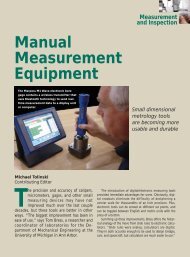
<strong>Moving</strong>-<strong>Part</strong><br />
<strong>Metrology</strong><br />
Faro Laser-Tracker helps align rollers used in paper-making process.<br />
<strong>Metrology</strong> is growing in importance<br />
for almost every<br />
manufactured product. Because<br />
of:<br />
• The penalties of warranty claims or products<br />
rejected by customers.<br />
Stiffer customer requirements for accuracy and<br />
cleanliness.<br />
Need to inspect raw materials and components<br />
from suppliers.<br />
<strong>Metrology</strong><br />
Is it there?<br />
Is it right?<br />
Robert B. Aronson<br />
Senior Editor<br />
New demands are being placed on gage suppliers.<br />
One area of particular importance is automatic monitoring<br />
of manufacturing processes. This can range from a<br />
simple gage for registering the presence or absence of a<br />
part to sensors that evaluate crucial component elements.<br />
In the simplest case, you only need to know if the<br />
part is there or not.<br />
This task is handled by a very simple contact or<br />
light-beam-breaking device.<br />
A more complex task is checking for the presence or<br />
absence of a part’s feature. How’s the surface finish? Is
<strong>Metrology</strong><br />
the setscrew there? Did the two part pieces mesh? The<br />
answers require a more sophisticated system with the ability<br />
to identify shapes. Overall, the goal for all systems is to<br />
improve a part’s production speed and precision. Here’s a<br />
look at some of them.<br />
Aiding the assembly of large products, such as airplanes,<br />
or monitoring the assembly of complex machines,<br />
takes an instrument like the Laser Tracker from Faro<br />
(Lake Mary, FL)<br />
“New demands are being<br />
placed on gage suppliers.”<br />
The Laser Tracker, which is designed for shop-floor<br />
operation, consists of a laser distance meter, two precision<br />
encoders, and software to calculate, store, and display<br />
the data from targets mounted on the product<br />
being measured. A beam-steering system locates the target,<br />
then the lasers lock on and take readings. Driven<br />
by two servomotors, the system updates position at a<br />
rate of 1000 times per second. The Laser Tracker,<br />
which can weigh up to 20 kg, measures objects in the<br />
Leica T-Mac system uses a laser detector carried by a robot.<br />
0–70-m range. Area resolution is 0.158 µm with a<br />
repeatability of 1 µm.<br />
The data determine the distance between the Tracker<br />
and the reflecting mirror as well as the horizontal and vertical<br />
angles between the Tracker and the reflecting mirror.<br />
With this information, the reflector’s position can be<br />
found in three axes (X, Y and Z).<br />
Systems such as the Tracker are needed to replace the<br />
simple hand tools and instruments that are still used in<br />
the assembly and repair of machine tools. Usually the<br />
data gathered by these simple tools do not meet the<br />
standards of accuracy required today. First, the measurements<br />
may be off, plus there is no documentation to<br />
prove the measurements were made.<br />
“Gaging for automatic process control through<br />
machine-tool compensation has been available for a number<br />
of years,” explains Director of Precision Gages,<br />
George J. Schuetz, Mahr Federal (Providence, RI). When<br />
first implemented, tool-compensation software was loaded<br />
onto the machine tool controller, and operators would<br />
input measurement results into the controller manually,<br />
allowing the software to calculate machine-tool offsets.<br />
More recently, with the advent of digital electronics, the
<strong>Metrology</strong><br />
gages are hardwired to the controller. The software gathers<br />
data on various parameters as measured by the gaging,<br />
and machine tool offsets are calculated to improve the<br />
process and manufacture parts closer to their desired size.<br />
“Both these scenarios can pose problems.” says<br />
Schuetz. “The first is that manual data entry is time consuming,<br />
and prone to input errors. The second problem<br />
associated with electronic gaging is that when a machine<br />
must make multiple dimensions, each gage requires a<br />
cable to be connected to the controller. This makes it<br />
nearly impossible when checking multiple dimensions in<br />
a machine as the cables tend to get in the way, and provide<br />
a safety issue.”<br />
In addition, taking the part out of the gage for all<br />
measurements slows down the measurement process, and<br />
can make it difficult to get the part back in the machine to<br />
the same position.<br />
However, the new-generation hand tools and gages have<br />
wireless capabilities so that multiple gages can be wirelessly<br />
connected to the machine controller. They provide wireless<br />
data collection and free the operator to manipulate the gages<br />
in the machine for easy data collection.<br />
“The benefits are fast data collection, positive feedback so<br />
the operator knows when the data have been collected, and<br />
instantaneous machine-tool offsets are made to improve the<br />
process. Plus, this all works seamlessly with the machine-tool<br />
controller and its compensation package,” concludes Schuetz.<br />
Mahr Federal now offers a wireless solution that provides<br />
the features that are key to making the system work. It<br />
tells the operator when a measurement is transferred successfully.<br />
Each transmitter in this system has both an audio<br />
and visual indication of a successful data transmission.<br />
Because of the electromagnetic noise in the shop, the<br />
system has to ensure that the right frequency is used to get<br />
the transmission through the noise, ensure the transmis-<br />
sion has been received by the computer, and that instantaneous<br />
feedback is given to the operator.<br />
The system can handle up to 99 independently functioning<br />
transmitters, has its own identification code, and<br />
puts data into the correct area of the controlling software.<br />
By placing the data into places in memory that are<br />
transparent to the software, it’s easier to transfer to auto<br />
comp or spc programs. At the same time, the data can be<br />
stored for long-term archiving.<br />
A tracker-machine wireless control sensor, the T-Mac<br />
from Leica (Wixom, MI) is mounted on moving robots,<br />
machines, or parts whose position is to be monitored in six<br />
degrees of freedom. This measurement device was developed<br />
for tracking tasks that are difficult or when it is<br />
impractical to have a worker hold a unit.<br />
“The new generation of<br />
gages has wireless capabilities.”<br />
The unit operates the human interface element and<br />
contact probe. It has reflector nests for calibration and<br />
easy orientation, plus a mechanical interface to the calibration<br />
tool. Insensitive to environmental light, the Leica<br />
T-Mac offers operation measurement volumes of up to 30<br />
m, and reportedly has a wider acceptance angle than comparable<br />
system: pitch 45º, yaw ±45°, and roll 360º.<br />
Point rate output is 1000 points per second with a measurement<br />
accuracy of 60 µm in a measurement volume of 15<br />
m. Top tracking speed is greater than 1 µsec. The Leica T-<br />
Mac incorporates acoustic process information feedback for<br />
ease-of-use, as well as visual feedback for power on, in-view<br />
and in-distance status, and for process information.<br />
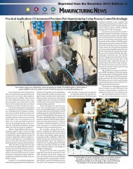
X-Rite Inc. (Grand Rapids, MI) specializes in color<br />
measurement and color management, offering hardware,<br />
Scanner from X-Rite Inc. evaluates paint reflections to ensure the same color on all vehicle panels.
<strong>Metrology</strong><br />
software, and services for measuring, formulating, and<br />
matching color.<br />
One of the problems they recently solved involved the<br />
fact that auto makers have difficulty measuring the color<br />
and appearance of bumper, panels, and other exterior surfaces<br />
with coatings that contain “sparkle.” This is because<br />
existing instruments reportedly cannot measure the paint’s<br />
apparent different appearance under different illuminations<br />
and observation angles. X-Rite developed an instrument,<br />
the xDNA, that takes advantage of the fact that<br />
each paint has a unique, 3-D mathematical model, similar<br />
to the way that each person has a unique DNA structure.<br />
The xDNA is said to speed introduction of new<br />
paints, improve the first-time quality of products being<br />
coated, and reduce manufacturing problems that occur<br />
on the factory floor.<br />
The xDNA uses the X-ColorQC software package that<br />
manipulates the data with proprietary algorithms to generate<br />
graphs that show unique characteristics of a specific<br />
Mahr-Federal hand-held surface inspector detects surface flaws.<br />
paint. The unit’s analysis may solve problems by modifying<br />
existing equipment. And with the data generated, it’s<br />
possible to develop more exact quality standards that<br />
quickly indicate when a process is going out of control.<br />
The 1-kg unit has a 31-point spectrophotometer designed<br />
for use on the factory floor. Measurement time is about 1<br />
sec, with calculation and display in a total of 2 sec. It is powered<br />
by a battery that lasts up to 16 hr, or enough power to<br />
take about 1000 five-angle measurements. The instrument<br />
can also operate from an AC adapter.<br />
CogniTens (Wixom, MI), a division of Hexagon, has a<br />
measuring system that uses a head with three cameras and a<br />
white-light source. The company’s market is heavily automotive<br />
for both setup and production operations. For<br />
example in setup, a scan may detect a flaw that is traced<br />
back to discontinuity in the stamping die.<br />
“There is now a need to<br />
inspect raw materials and<br />
components from suppliers.”<br />
In operation, three 1.4-megapixel cameras fire simultaneously.<br />
After a scan, the control compares the scan<br />
data with the existing CAM file and any discrepancies<br />
are recorded. Typical applications are spacing between<br />
certain features on the part such as holes, and checking<br />
die performance. Scans have an accuracy<br />
of ±0.05 mm when scanning<br />
surfaces and ±0.08 mm when checking<br />
part features.<br />
A CogniTens unit may be fixed to<br />
check all parts or every few parts.<br />
Portable units are used for specific<br />
flaw-detection problems. The unit can<br />
also reverse engineer. When no CAD<br />
file exists the CogniTens can scan the<br />
part and generate a file.<br />
One application was checking tiles<br />
on a NASA space shuttle. These craft<br />
are protected by approximately<br />
24,000 individual and uniquely<br />
shaped ceramic tiles. After each mission<br />
all these tiles have to be checked<br />
for possible damage. A CogniTens 3-<br />
D measurement system, the Optigo, is<br />
used for the job. The system measures<br />
each tile in less than a millisecond.<br />
The digital shape information is then<br />
fed into a computer that creates a<br />
specific CAD file for each tile.<br />
“What kind of equipment, or system, we supply depends<br />
on the customer’s application,” says Gary Scheneder, manager<br />
of new business development of <strong>Marposs</strong> Corp.<br />
(Auburn Hills, MI). “But generally the goal is to determine<br />
what kind of feedback is needed to generate the information<br />
necessary to correct any problems.”<br />
And often <strong>Marposs</strong> configures existing standard products<br />
to meet special customer needs. One example of this
<strong>Metrology</strong><br />
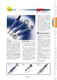
type is the M39S measuring system.<br />
The customer wanted a gage that<br />
would measure true roundness and<br />
concentricity on the shop floor in a<br />
nonenvironmentally controlled<br />
atmosphere. Plus, it had to measure<br />
roundness with a tolerance of 0.6<br />
µm. According to the company, in<br />
the past, parts with this level of tolerances<br />
could only have been measured<br />
in a gage lab using a specialized<br />
roundness geometry instrument.<br />
The M39S system can measure<br />
100% of the parts produced without<br />
increasing process time. It can<br />
help achieve quality and productivity<br />
goals by utilizing gages out on<br />
SEPTEMBER 2008<br />
<strong>Marposs</strong> M39S was designed to<br />
be easily adapted to handle<br />
a family of parts.<br />
the shop floor instead of in a laboratory<br />
environment.<br />
“That unit has opened markets<br />
not only in the fuel-injector arena but<br />
also in the measurement of gear<br />
bores, valve sleeves, spools, and other<br />
high-precision components.<br />
“We chiefly apply electronic technology<br />
to make measurements, and<br />
one of our design strong points is the<br />
ability to mount a large number of<br />
transducers in a small space. This<br />
means a customer has more critical<br />
data about a part in a single setup.<br />
Often customers are surprised how<br />
much cost-saving information is<br />
available,” he concludes.■<br />
Copyright Notice: COPYRIGHT 2008 BY SOCIETY OF MANUFACTURING ENGINEERS. ALL RIGHTS<br />
RETAINED. THIS ARTICLE MAY ONLY BE VIEWED OR PRINTED ONE (1) TIME FOR PERSONAL USE.<br />
USER MAY NOT SAVE ANY TEXT OR GRAPHICAL ITEMS TO HARD DRIVES OR DUPLICATE THIS<br />
ARTICLE IN WHOLE OR IN PART IN ANY MEDIUM. THIS ARTICLE APPEARS WITH PERMISSION<br />
FROM MANUFACTURING ENGINEERING ® , THE OFFICIAL PUBLICATION OF THE SOCIETY OF<br />
MANUFACTURING ENGINEERS (SME). WWW.SME.ORG