Technical Specification SAGEM ICDS-10 - Styles & Scribbles
Technical Specification SAGEM ICDS-10 - Styles & Scribbles
Technical Specification SAGEM ICDS-10 - Styles & Scribbles

Create successful ePaper yourself
Turn your PDF publications into a flip-book with our unique Google optimized e-Paper software.
<strong>Technical</strong> <strong>Specification</strong><br />
<strong>SAGEM</strong> <strong>ICDS</strong>-<strong>10</strong><br />
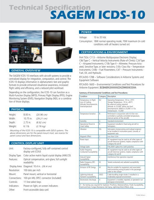
GENERAL OVERVIEW<br />
The <strong>SAGEM</strong> <strong>ICDS</strong>-<strong>10</strong> interfaces with aircraft systems to provide a<br />
centralized display for integration, computation, and control. The<br />
<strong>ICDS</strong>-<strong>10</strong> displays information in alphanumeric text and graphic<br />
formats to provide enhanced situational awareness, increased<br />
fl ight safety and effi ciency, and a reduced pilot workload.<br />
Depending on the confi guration, the <strong>ICDS</strong>-<strong>10</strong> can function as a<br />
Multi-Function Display (MFD), Primary Flight Display (PFD), Engine<br />
Monitoring System (EMS), Navigation Display (ND), or a combination<br />
of those displays.<br />
PHYSICAL<br />
Height: 8.00 in. (20.96 cm)<br />
Width: <strong>10</strong>.75 in. (29.21 cm)<br />
Depth: 2.75 in. (8.92 cm)<br />
Weight: 6.1 lb (2.76 kg)<br />
Mounting of the <strong>ICDS</strong>-<strong>10</strong> is compatible with DZUS systems. The<br />
above dimensions are for the panel-mount inset; see reverse for<br />
panel cutout and face dimensions.<br />
CONTROL DISPLAY UNIT<br />
Unit: Factory-confi gured, fully self-contained control<br />
display unit (CDU)<br />
Display Type: Color active matrix liquid crystal display (AMLCD)<br />
Features: Optical compensation, anti-glare, full sunlight<br />
readability<br />
Display Area: Diagonal: <strong>10</strong>.4 in. (26.4 cm)<br />
Resolution: <strong>10</strong>0 dots per inch<br />
Mount: Panel mount, vertical or horizontal<br />
Connections: <strong>10</strong>0-pin MIL-SPEC connector (included)<br />
Controls: 11 line-select keys<br />
Indicators: Power-on light, on-screen indicators<br />
Other: Front-accessible data card<br />
POWER<br />
Voltage: <strong>10</strong> to 35 Vdc<br />
Consumption: 18W normal operating mode; 70W maximum (in cold<br />
conditions with all heaters turned on)<br />
CERTIFICATIONS & ENVIRONMENT<br />
FAA TSOs: C113 – Airborne Multipurpose Electronic Display;<br />
C8d Type C – Vertical Velocity Instruments (Rate-of-Climb); C2d Type<br />
C – Airspeed Instruments; C<strong>10</strong>b Type II – Altimeter, Pressure Actuated,<br />
Sensitive Type, or later revisions; C43c Class IIIa – Temperature<br />
Instruments; C44b – Fuel Flowmeters; C47 – Pressure Instruments -<br />
Fuel, Oil, and Hydraulic<br />
RTCA/DO-178B – Software Considerations in Airborne Systems and<br />
Equipment Software<br />
RTCA/DO-160D – Environmental Conditions and Test Procedures for<br />
Airborne Equipment: [B2]BAB[RG]XXXXXXZZAZZWM[XXE3]XXA<br />
Summary of Environmental Conditions and Test Procedures:<br />
Condition Category Description<br />
Temperature, In-Flight<br />
Loss of Cooling,<br />
Altitude, Decompression,<br />
Overtemperature<br />
B2 Operating Temperature: -55 to +70°C<br />
Storage Temperature: -55 to +85°C<br />
No external cooling required<br />
Altitude: to 25,000’ above sea level<br />
Decompression: 8000 to 25,000’ in 15s<br />
Overpressure: -15,000’<br />
Temperature Variation B Performed in conjunction with 4.0 (for noncontrolled<br />
or partially controlled temperature,<br />
internal section of the aircraft)<br />
Humidity A Standard environment<br />
Operational Shock &<br />
Crash Safety<br />
B Equipment installed in fi xed-wing aircraft or<br />
helicopters<br />
Vibration RG Helicopters (reciprocating and turbojet engines)<br />
to be installed in instrument panel, console, or<br />
equipment rack<br />
Magnetic Effect Z Less than 0.3m<br />
Power Input Z DC equipment may be used on all other types of<br />
aircraft electrical systems; implies compliance with<br />
Category A() and B<br />
Voltage Spike A Fifty 600V spikes/min, both polarities<br />
Audio Frequency<br />
Conducted Susceptibility<br />
Z DC equipment may be used on all other types of<br />
aircraft electrical systems; implies compliance with<br />
Category A() and B<br />
Induced Signal<br />
Susceptibility<br />
Z Interference-free operation required<br />
Radio Frequency (RF)<br />
Susceptibility<br />
W Tested conducted and radiated susceptibility<br />
Emission of RF Energy M May be suitable for equipment and associated<br />
interconnecting wiring located in the passenger<br />
cabin or the cockpit<br />
Lightning-Induced<br />
Transient Susceptibility<br />
XXE3 Cable bundling single-stroke 3 installed in a<br />
moderately exposed environment<br />
Electrostatic Discharge A Equipment is installed, repaired, or operated in an<br />
aerospace environment<br />
X – No testing was required for Explosion Proofness, Waterproofness, Fluids Susceptibility,<br />
Sand and Dust, Fungus Resistance, Salt Spray, Lightning Direct Effects, Icing<br />
TS-0500-<strong>10</strong>0 Rev A
TECHNICAL SPECIFICATION | <strong>SAGEM</strong> <strong>ICDS</strong>-<strong>10</strong><br />
INTERFACES AND COMPATIBILITY<br />
Video input (composite) NTSC/PAL (optional)<br />
NVG (night vision goggles) compatible (optional)<br />
GPS RS-232 (ARNAV Star 5000, Garmin 430/530, GNS 480,<br />
others)<br />
NAV Source (Garmin 430/530, GNS 480, KX 165, KNS 80/81,<br />
Collins, others)<br />
ADF (KR 87, Collins, others)<br />
ARINC 429 (Garmin VOR/ILS, GPS; Honeywell EPIC, others)<br />
Discrete inputs options include pilot in command, PFD show<br />
engines, PFD/MFD mode, maintenance mode, others<br />
Discrete outputs include gauge in caution range, latched exceedance,<br />
primary engine page not selected, others<br />
Other interfaces and applications, not listed, may be compatible.<br />
Contact Sagem Avionics, Inc. for details.<br />
INSTALLATION REQUIREMENTS<br />
Cooling: No external cooling necessary; requires clearance<br />
for internal cooling fan and vents<br />
Breaker: Klixon 5A trip-free circuit breaker* or equivalent<br />
Wiring: Power input wires* (18 or 20 AWG), signal wires*<br />
(22 or 24 AWG), <strong>10</strong>0-pin adapter<br />
*Not supplied: circuit breaker, wiring<br />
NOTES<br />
For safety reasons, operation of the <strong>ICDS</strong>-<strong>10</strong> must be learned on<br />
the ground.<br />
For maximum versatility, the <strong>ICDS</strong>-<strong>10</strong> modes of operation and<br />
confi guration are factory-set for the specifi c aircraft.<br />
www.sagemavionics.com<br />
TEXAS DIVISION<br />
2701 Forum Drive<br />
Grand Prairie, TX 75052 USA<br />
Tel.: +1.972.314.3600<br />
Fax: +1.972.314.3640<br />
WASHINGTON DIVISION<br />
16923 Meridian East<br />
Puyallup, WA 98375 USA<br />
Tel.: +1.253.848.6060<br />
Fax: +1.253.848.3555<br />
<strong>SAGEM</strong> DÉFENSE SÉCURITÉ<br />
27, rue Leblanc<br />
75512 PARIS CIDEX 15 France<br />
Tel.: +33 (0) 1 58 11 78 00<br />
Fax: +33 (0) 1 58 11 78 50<br />
©2006 Sagem Avionics, Inc. All rights reserved. Printed in USA. Specifi cations are subject to change without notice.<br />
The <strong>SAGEM</strong> logo is a registered trademark of <strong>SAGEM</strong> S.A. DZUS is a registered trademark of McKechnie Specialized Products Limited.<br />
TS-0500-<strong>10</strong>0 Rev A