Dold Emergency Stop Monitor BD5935 - United Automation, Inc.
Dold Emergency Stop Monitor BD5935 - United Automation, Inc.
Dold Emergency Stop Monitor BD5935 - United Automation, Inc.

Create successful ePaper yourself
Turn your PDF publications into a flip-book with our unique Google optimized e-Paper software.
0221548<br />
Safety technique<br />
<strong>Emergency</strong> <strong>Stop</strong> module BD 5935<br />
safemaster<br />
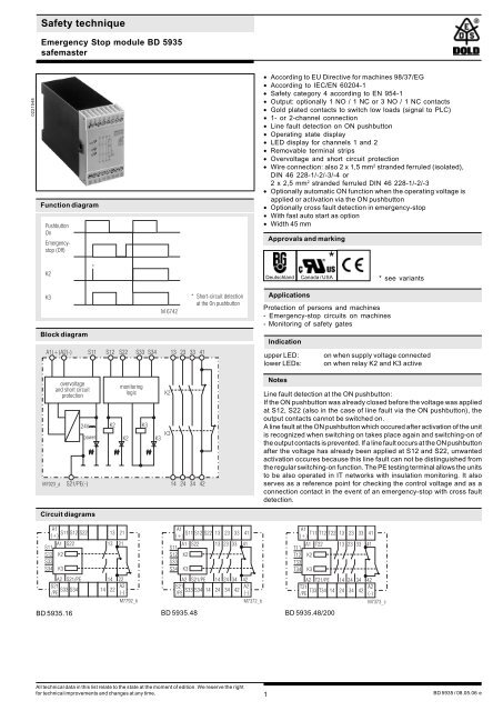
Function diagram<br />
Pushbutton<br />
On<br />
<strong>Emergency</strong>stop<br />
(Off)<br />
K2<br />
K3<br />
Block diagram<br />
A1(+)A2(-) S11 S12 S22 S33 S34 13 23 33 41<br />
overvoltage<br />
and short circuit<br />
protection<br />
24V<br />
power<br />
M7023_a S21/PE(-) 14 24 34 42<br />
Circuit diagrams<br />
A1<br />
S11 S12 S22<br />
(+)<br />
S11<br />
A1 S22<br />
S12<br />
S33<br />
K2<br />
S34 K3<br />
A2 S21/PE<br />
S21<br />
S33 S34<br />
/PE<br />
*<br />
K2<br />
monitoring<br />
logic<br />
K2<br />
13 21<br />
13 21<br />
14 22<br />
14 22<br />
A2<br />
(-)<br />
M7792_b<br />
K3<br />
K3<br />
M 6742<br />
K2<br />
K3<br />
* Short-circuit detection<br />
at the On pushbutton<br />
A1<br />
S11 S12 S22 13 23 33 41<br />
(+)<br />
S11<br />
A1 S22 13 23 33 41<br />
S12<br />
S33<br />
K2<br />
S34 K3<br />
A2 S21/PE 14 24 34 42<br />
S21<br />
S33 S34 14<br />
/PE<br />
24 34 42<br />
A2<br />
(-)<br />
M7372_b<br />
• According to EU Directive for machines 98/37/EG<br />
• According to IEC/EN 60204-1<br />
• Safety category 4 according to EN 954-1<br />
• Output: optionally 1 NO / 1 NC or 3 NO / 1 NC contacts<br />
• Gold plated contacts to switch low loads (signal to PLC)<br />
• 1- or 2-channel connection<br />
• Line fault detection on ON pushbutton<br />
• Operating state display<br />
• LED display for channels 1 and 2<br />
• Removable terminal strips<br />
• Overvoltage and short circuit protection<br />
• Wire connection: also 2 x 1,5 mm 2 stranded ferruled (isolated),<br />
DIN 46 228-1/-2/-3/-4 or<br />
2 x 2,5 mm 2 stranded ferruled DIN 46 228-1/-2/-3<br />
• Optionally automatic ON function when the operating voltage is<br />
applied or activation via the ON pushbutton<br />
• Optionally cross fault detection in emergency-stop<br />
• With fast auto start as option<br />
• Width 45 mm<br />
1<br />
Approvals and marking<br />
Applications<br />
Protection of persons and machines<br />
- <strong>Emergency</strong>-stop circuits on machines<br />
- <strong>Monitor</strong>ing of safety gates<br />
Indication<br />
upper LED: on when supply voltage connected<br />
lower LEDs: on when relay K2 and K3 active<br />
Notes<br />
Line fault detection at the ON pushbutton:<br />
If the ON pushbutton was already closed before the voltage was applied<br />
at S12, S22 (also in the case of line fault via the ON pushbutton), the<br />
output contacts cannot be switched on.<br />
A line fault at the ON pushbutton which occured after activation of the unit<br />
is recognized when switching on takes place again and switching-on of<br />
the output contacts is prevented. If a line fault occurs at the ON pushbutton<br />
after the voltage has already been applied at S12 and S22, unwanted<br />
activation occures because this line fault can not be distinguished from<br />
the regular switching-on function. The PE testing terminal allows the units<br />
to be also operated in IT networks with insulation monitoring. It also<br />
serves as a reference point for checking the control voltage and as a<br />
connection contact in the event of an emergency-stop with cross fault<br />
detection.<br />
A1<br />
T11 T12 T22 13 23<br />
(+)<br />
33<br />
41<br />
T11<br />
A1 T22 13 23 33 41<br />
T12<br />
T33<br />
K2<br />
T34 K3<br />
A2 T21/PE 14 24 34 42<br />
T21<br />
T33 T34 14<br />
/PE<br />
24 34 42<br />
A2<br />
(-)<br />
BD 5935.16 BD 5935.48 BD 5935.48/200<br />
All technical data in this list relate to the state at the moment of edition. We reserve the right<br />
for technical improvements and changes at any time.<br />
*<br />
Deutschland Canada / USA<br />
M7373_c<br />
* see variants<br />
BD 5935 / 08.05.06 e
M5960<br />
Unit programming<br />
Notes<br />
Because of the gold-plated contacts the BD 5935 can be used to switch<br />
small loads 1 mVA ... 7 VA, 1 mW ... 7 W in the range of 0,1 ... 60 V, 1 ...<br />
300 mA. The gold-plated contacts allow also to switch the maximum<br />
current but the gold plating will be burnt off. After that the contacts cannot<br />
be used any more to switch the small loads.<br />
One or more extension modules BN 3081 or external contactors with<br />
positively driven contacts can be used to multiply the number of contacts<br />
of the emergency-stop module BD 5935.<br />
The switches S1 and S2 are provided for the following selection<br />
possibilities: Automatic-start, manual-start and emergency-stop with or<br />
without cross fault detection. These switches are located behind the front<br />
cover panel (see unit programming diagrams).<br />
Switch S2 is for selecting automatic or manual Start. In addition, terminals<br />
S33 and S34 must be jumpered for "automatic start function".<br />
Selection of the operating mode with or without cross fault detection at the<br />
emergency-stop pushbutton is performed via the switch S1. The unit<br />
must be connected as shown in the application example.<br />
ATTENTION - AUTOMATIC START!<br />
According to IEC/EN 60 204-1 part 9.2.5.4.2 it is not<br />
allowed to restart automatically after emergency stop.<br />
Therefore the machine control has to disable the<br />
automatic start after emergency stop.<br />
Technical data<br />
Input<br />
Nominal voltage U N : AC 24, 48, 110, 127, 230, 240 V<br />
DC 24 V<br />
Voltage range: AC 0,85 ... 1,1 U N<br />
at 10% residual ripple: DC 0,9 ... 1,2 U N<br />
at 48% residual ripple: DC 0,8 ... 1,1 U N<br />
Nominal consumption: AC approx. 4 VA, DC approx. 2 W<br />
Nominal frequency: 50 / 60 Hz<br />
Recovery time: 0,5 s after activating the emergencystop<br />
button.<br />
If the line fault detection of the ONbutton<br />
is be active, the device must<br />
stay off for approx. 5 sec.<br />
Control voltage at S11: DC 24 V<br />
Control current via S12, S22: approx. 35 mA ± 25 % at U N<br />
Minimum voltage at<br />
terminal S12, S22: DC 21 V when unit is activated<br />
Output<br />
plate<br />
Contacts<br />
BD 5935.16: 1 NO / 1 NC contacts<br />
BD 5935.48: 3 NO / 1 NC contacts<br />
The NO contacts are safety contacts.<br />
ATTENTION! The NC contacts 21-22<br />
or 41-42 can only be used for<br />
monitoring.<br />
2<br />
Technical data<br />
Operate time<br />
activation via ON pushbutton:50 ms - 25 % + 50 %<br />
automatic ON function: 1 s - 25 % + 50 %, as option also<br />
with shorter on-delay (see variants)<br />
Release time<br />
opening in secondary circuit<br />
(S12-S22): 25 ms - 25 % + 50 %<br />
opening in supply circuit: 50 ms - 25 % + 50 %<br />
Contact type: relay, positively-driven<br />
Rated output voltage: AC 250 V<br />
DC: see arc limit curve<br />
Thermal current I th : see quadratic total current limit curve<br />
(max. 10 A in one contact path)<br />
Switching capacity<br />
to AC 15<br />
for NO contact: AC 5 A / 250 V IEC/EN 60 947-5-1<br />
for NC contact: AC 2 A / 250 V IEC/EN 60 947-5-1<br />
Electrical life<br />
to AC 15 at 2 A, AC 230 V: 10 5 switching cycles IEC/EN 60 947-5-1<br />
Permissible operating<br />
frequency: 600 switching cycles / h<br />
Short circuit strength<br />
max. fuse rating: 6 A gL IEC/EN 60 947-5-1<br />
max. line circuit breaker: C 10 A<br />
Mechanical life: 10 x 10 6 switching cycles<br />
General data<br />
M7483<br />
Operating mode: Continuous operation<br />
Temperature range: - 15 ... + 55 °C<br />
at max. 90% humidity<br />
Clearance and creepage<br />
distances<br />
overvoltage category /<br />
contamination level: 4 kV / 2 IEC 60 664-1<br />
EMC<br />
Electrostatic discharge: 8 kV (air) IEC/EN 61 000-4-2<br />
Fast transients: 2 kV IEC/EN 61 000-4-4<br />
Surge voltages<br />
between<br />
wires for power supply: 1 kV IEC/EN 61 000-4-5<br />
between wire and ground: 2 kV IEC/EN 61 000-4-5<br />
Degree of protection: Housing: IP 40* IEC/EN 60 529<br />
Terminals: IP 20 IEC/EN 60 529<br />
* when front plate is removed to<br />
set switches, protection class IP 40<br />
is not valid<br />
Housing: Thermoplastic with V0 behaviour<br />
according to UL subject 94<br />
Vibration resistance: Amplitude 0,35 mm IEC/EN 60 068-2-6<br />
frequency 10 ... 55 Hz<br />
Climate resistance: 15 / 055 / 04 IEC/EN 60 068-1<br />
Terminal designation: EN 50 005
Technical data<br />
Wire connection: 1 x 4 mm 2 solid or<br />
1 x 2,5 mm 2 stranded ferruled (isolated)<br />
or<br />
2 x 1,5 mm 2 stranded ferruled (isolated)<br />
DIN 46 228-1/-2/-3/-4 or<br />
2 x 2,5 mm 2 stranded ferruled<br />
DIN 46 228-1/-2/-3<br />
Wire fixing: Plus-minus terminal screws M3.5,<br />
box terminal with wire protection<br />
Mounting: DIN rail IEC/EN 60 715<br />
Weight: 450 g<br />
Dimensions<br />
Width x height x depth: 45 x 74 x 121 mm<br />
Switching voltage U [V]<br />
Standard type<br />
BD 5935.48 DC 24 V<br />
Article number: 0045456 stock item<br />
• Output: 3 NO / 1 NC contacts<br />
• Nominal voltage U N : DC 24 V<br />
• Width: 45 mm<br />
Variants<br />
BD 5935._ _/61: with UL-approval<br />
BD 5935.48/200: special terminal arrangement<br />
see diagram<br />
BD 5935.48/324: with fast auto start:<br />
typ. 500 ms, without line fault<br />
detection on ON-button<br />
BD 5935.48/824: with fast auto start:<br />
typ. 110 ms, without line fault<br />
detection on ON-button<br />
Ordering example of Variants<br />
BD 5935 .48 /_ _ _ AC 230 V 50/60 Hz<br />
Characteristics<br />
250<br />
200<br />
150<br />
100<br />
50<br />
0<br />
1<br />
2<br />
3 4 5 6 7 8 9 10<br />
Switching current I [A]<br />
M 6732<br />
Arc limit curve under resistive load<br />
Nominal frequency<br />
Nominal voltage<br />
Variant, if required<br />
Contacts<br />
Type<br />
Single-channel emergency-stop circuit. This circuit has no redundancy in<br />
the emergency-stop control circuit.<br />
Please note "Unit programming" !<br />
Switches in pos.: S1 no cross fault detection<br />
S2 manual start<br />
Two-channel emergency-stop circuit without cross fault detection.<br />
Please note "Unit programming" !<br />
Switches in pos.: S1 no cross fault detection<br />
S2 manual start<br />
3<br />
Application examples<br />
Contact reinforcement with external contactors, controlled with one<br />
contact path.<br />
Please note "Unit programming" !<br />
Switches in pos.: S1 no cross fault detection<br />
S2 manual start
Application examples<br />
Contact reinforcement by external contators, controlled with 2 contact<br />
paths. With switching current > 10 A, the output contacts can be reinforced<br />
by external contactors with positively-driven contacts. The function of the<br />
external contactors is monitored by looping the NC contacts into the<br />
making circuit (terminals S33-S34).<br />
Please note "Unit programming" !<br />
Switches in pos.: S1 no cross fault detection<br />
S2 manual start<br />
Two-channel emergency-stop circuit with cross fault detection.<br />
Please note "Unit programming" !<br />
Switches in pos.: S1 cross fault detection<br />
S2 manual start<br />
Two-pole emergency-stop with emergency-stop control device in the<br />
supply circuit.<br />
Application for long emergency-stop loops in which the control voltage<br />
dropped below the minimum voltage of 21 V.<br />
Important:<br />
Single faults (line shorts over the emergency-stop control device) are not<br />
identified with this external circuit.<br />
Please note "Unit programming" !<br />
Switches in pos.: S1 no cross fault detection<br />
S2 manual start<br />
E. DOLD & SÖHNE KG D-78114 Furtwangen<br />
e-mail dold-relays@dold.com internet http://www.dold.com<br />
Two-channel monitoring of a safety gate.<br />
The switch of S12 must close simultaneously with S22 or later.<br />
Please note "Unit programming" !<br />
Switches in pos.: S1 no cross fault detection<br />
S2 manual start<br />
4<br />
Application example<br />
• P.O. Box 1251 • Phone +49 7723 / 65 40 • Fax +49 7723 / 654 356