Service manual Puma 20/40
Service manual Puma 20/40
Service manual Puma 20/40

You also want an ePaper? Increase the reach of your titles
YUMPU automatically turns print PDFs into web optimized ePapers that Google loves.
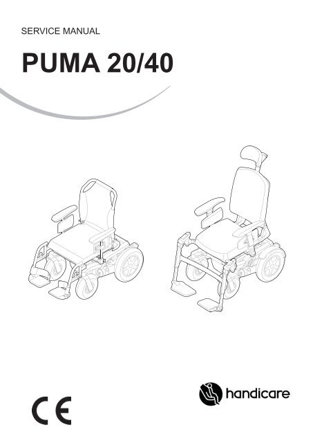
SERVICE MANUAL<br />
PUMA <strong>20</strong>/<strong>40</strong>
2 |<br />
© <strong>20</strong>11 Handicare<br />
<strong>Puma</strong> <strong>20</strong>/<strong>40</strong><br />
All rights reserved.<br />
The information provided herein may not be reproduced and/or published in any form, by print, photo print, microfi lm or any other<br />
means whatsoever (electronically or mechanically) without the prior written authorisation of Handicare.<br />
The information provided is based on general data concerning the constructions known at the time of the publication of this<br />
<strong>manual</strong>. Handicare executes a policy of continuous improvement and reserves the right to changes and modifi cations.<br />
The information provided is valid for the product in its standard version. Handicare cannot be held liable for possible damage<br />
resulting from specifi cations of the product deviating from the standard confi guration.<br />
The available information has been prepared with all possible diligence, but Handicare cannot be held liable for possible errors in<br />
the information or the consequences thereof.<br />
Handicare accepts no liability for loss resulting from work executed by third parties.<br />
Names, trade names, etc. used by Handicare may not, as per the legislation concerning the protection of trade names, be<br />
considered as being available.
<strong>Puma</strong> <strong>20</strong>/<strong>40</strong><br />
1 Introduction <strong>Service</strong> <strong>manual</strong> <strong>Puma</strong> <strong>20</strong>/<strong>40</strong> ............................................................................................................ 5<br />
1.1 This <strong>manual</strong> 5<br />
1.2 Identifi cation of the product 5<br />
1.3 Symbols used in this <strong>manual</strong> 6<br />
2 Safety ................................................................................................................................................................... 7<br />
2.1 Maximum User weight reduction when <strong>Puma</strong> <strong>20</strong> options are installed on a <strong>Puma</strong> <strong>40</strong>! 7<br />
2.2 Personnel qualifi cation 7<br />
2.3 Cautions and warning statements 7<br />
2.4 Used decals on the wheelchair 8<br />
3 Tools, parts and components ............................................................................................................................. 10<br />
3.1 Tools 10<br />
3.2 Tools electronics 10<br />
4 Spare parts ......................................................................................................................................................... 11<br />
4.1 Use of the parts lists 11<br />
4.2 Carrier and seat adjustments 12<br />
4.3 Wiring and modules Shark 23<br />
4.4 Wiring and modules R-net 25<br />
4.5 Wiring and modules DX2 27<br />
4.6 Wiring and modules VR-2 29<br />
5 <strong>Service</strong> instructions ............................................................................................................................................ 31<br />
5.1 Maintenance plan 31<br />
5.2 Assembly, replacement and adjustment instructions 32<br />
5.2.1 <strong>Puma</strong> <strong>20</strong> / <strong>Puma</strong> <strong>40</strong> Carrier 33<br />
5.2.2 Driving wheels (<strong>Puma</strong> <strong>20</strong>/<strong>40</strong>) 48<br />
5.2.3 Castor wheels 55<br />
5.2.4 Replacements 62<br />
5.2.5 Seat adjustments 73<br />
5.2.6 Seat tilt confi guration tables 84<br />
6 Trouble shooting ................................................................................................................................................. 90<br />
6.1 Shark faultfi nding table 90<br />
6.2 R-net faultfi nding table 91<br />
6.3 DX2 faultfi nding table 95<br />
6.4 VR-2 faultfi nding table 99<br />
7 Technical product information ........................................................................................................................... 102<br />
7.1 CE Declaration and standards 102<br />
7.2 Technical information 102<br />
7.3 Electrical diagram 104<br />
8 Warranty ........................................................................................................................................................... 112<br />
8.1 Provisions of warranty 112<br />
8.2 Liability provisions 113<br />
| 3
4 |<br />
<strong>Puma</strong> <strong>20</strong>/<strong>40</strong>
<strong>Puma</strong> <strong>20</strong>/<strong>40</strong><br />
1 Introduction <strong>Service</strong> <strong>manual</strong> <strong>Puma</strong> <strong>20</strong>/<strong>40</strong><br />
1.1 This <strong>manual</strong><br />
Introduction <strong>Service</strong> <strong>manual</strong> <strong>Puma</strong> <strong>20</strong>/<strong>40</strong> | 5<br />
This <strong>manual</strong> contains the instructions for repairs and general maintenance of the <strong>Puma</strong> <strong>20</strong>/<strong>40</strong> motor driven wheelchair.<br />
Mechanics who do repairs on this wheelchair must be well trained and familiar with the repair methods and the maintenance of<br />
the <strong>Puma</strong> <strong>20</strong>/<strong>40</strong> wheelchair.<br />
Always make sure that the work is carried out safely, particularly with respect to procedures requiring the wheelchair to be lifted<br />
up.<br />
We advise that you contact our service department before doing repair work on a wheelchair that has been involved in an<br />
accident.<br />
The following specifi cations are important when ordering parts:<br />
• Model<br />
• Year of manufacture<br />
• Colour<br />
• Identifi cation number<br />
• Part number<br />
• Name of the part concerned<br />
This information is provided on the identifi cation plate. See 'Identifi cation of the product'.<br />
Available documentation<br />
The following technical documentation is available / required to service this wheelchair:<br />
• User <strong>manual</strong><br />
• <strong>Service</strong> <strong>manual</strong><br />
<strong>Service</strong> and technical support<br />
For information concerning specifi c settings, maintenance or repair works please contact your supplier. He is always prepared to<br />
help you.<br />
Ensure you have at hand:<br />
• Model<br />
• Year of manufacture<br />
• Identifi cation number<br />
This information is provided on the identifi cation plate. See 'Identifi cation of the product'.<br />
1.2 Identifi cation of the product<br />
The identifi cation plate contains the following data:<br />
A. Model<br />
B. Year of manufacture<br />
C. Identifi cation number<br />
D. Use area indoors or outdoors<br />
E. Maximum load in kg
6 | Introduction <strong>Service</strong> <strong>manual</strong> <strong>Puma</strong> <strong>20</strong>/<strong>40</strong><br />
1.3 Symbols used in this <strong>manual</strong><br />
Warning symbol<br />
Follow the instructions next to this symbol closely.<br />
Not paying careful attention to these instructions could result in physical injury or damage to the wheelchair or the<br />
environment.<br />
ATTENTION!<br />
Suggestions and advice that help tasks or procedures involved to be carried out more easily.<br />
<strong>Puma</strong> <strong>20</strong>/<strong>40</strong><br />
Reference symbol<br />
The symbol refers to a separate user <strong>manual</strong>. This reference will indicate the specifi c user <strong>manual</strong> and the section<br />
to which is being referred.<br />
Pull the charge cord out of the battery charging connection of the electric wheelchair before carrying out any maintenance on the<br />
wheelchair.
<strong>Puma</strong> <strong>20</strong>/<strong>40</strong><br />
2 Safety<br />
2.1 Maximum User weight reduction when <strong>Puma</strong> <strong>20</strong> options are installed on a <strong>Puma</strong> <strong>40</strong>!<br />
Safety | 7<br />
In case one of the following <strong>Puma</strong> <strong>20</strong> options is installed on a <strong>Puma</strong> <strong>40</strong> carrier, the maximum user weight is reduced to 136 kg:<br />
• Sedeo Lite Seating System (or any Sedeo Lite component)<br />
• <strong>Puma</strong> <strong>20</strong> motors<br />
• <strong>Puma</strong> <strong>20</strong> Comfort suspension<br />
• <strong>Puma</strong> <strong>20</strong> Electrical tilt adjustment (0 - 25º)<br />
2.2 Personnel qualifi cation<br />
<strong>Service</strong> technicians:<br />
Repairs may only be carried out by trained and authorised service technicians.<br />
During the execution of their work, they are at all times fully responsible for the fulfi lment of locally applicable safety guidelines<br />
and standards.<br />
Temporary employees and persons in training may only carry out repair and replacement work under the supervision of an<br />
authorised service technician.<br />
2.3 Cautions and warning statements<br />
Safety<br />
Safety information is indicated with the warning symbol.<br />
• Follow the instructions carefully next to these warning symbols! Not paying careful attention to these instructions could result<br />
in physical injury or damage to the wheelchair or the environment. Where ever possible, safety information is provided in the<br />
relevant chapter.<br />
Temperature<br />
• Avoid physical contact with the wheelchair’s motors at all times. Motors are continuously in motion during use and can reach<br />
high temperatures. After use, the motors will cool down slowly. Physical contact could cause burns.<br />
• If you do not use the wheelchair, ensure that it is not exposed to direct sunlight for lengthy periods of time. Certain parts of the<br />
wheelchair, such as the seat, the back and the armrests can become hot if they have been exposed to full sunlight for too long.<br />
This may cause burns or allergic reactions to the skin.<br />
Interference precautions<br />
Precautions in combining seat adjustment settings<br />
When fi tting and optimizing different seating settings and functions, professionals should be aware that not all settings can be<br />
combined over the full range. There are limitations to take into account when using electrical tilt, although unlikely in average<br />
fi tting situations*. Combining extremer settings can cause the back of the seat frame to touch the carrier when tilting. This should<br />
be avoided since it could damage the wheelchair and can be avoided by making some concessions to one or more settings.<br />
Practical guidelines<br />
When fi tting a <strong>Puma</strong> <strong>20</strong>/<strong>40</strong> with electrical tilt to the needs of a specifi c client, professionals should check that the seat frame can<br />
tilt freely without the covers with refl ector at the back interfer with the carrier.<br />
When to expect interference?<br />
Interference is most likely to occur at low seat heights, especially in combination with large seat depth and centre of gravity set to<br />
the rear of the wheelchair. For detailed information, please refer to the seat tilt confi guration tables.<br />
How to avoid interference?<br />
You can resolve interference by:<br />
• Making the seat depth smaller (see seat adjustments, backrest adjustment)<br />
• Positioning the center of gravity forward (see seat adjustments, centre of gravity setting)<br />
• Increasing the seat height (see seat adjustments, seat height adjustment)<br />
• Choosing a different tilt module, an alternative mounting of the 0- 25° tilt module (see seat adjustments, adjusting the electrical<br />
seat tilt) or no tilt at all.<br />
• Also see the seat tilt confi guration tables.<br />
* In practice this rarely leads to problems. Firstly because interference mainly occurs when combining a low seat height and large seat depth, settings that rarely<br />
coincide in practice. Usually a low seat height means 'small under leg length', 'small person' so small seat depth. Secondly, in most cases a satisfactory solution can<br />
be created all the same.
8 | Safety <strong>Puma</strong> <strong>20</strong>/<strong>40</strong><br />
Seat adjustment factory settings<br />
Handicare will deliver a <strong>Puma</strong> wheelchair with default factory settings. These settings depend on the options ticked on the order<br />
form. When a confi guration is ordered that causes interference, Handicare applies modifi ed factory settings and informs the<br />
customer of this via a note included in the wheelchair delivery. The seat tilt confi guration tables also provide detailed information<br />
about factory settings.<br />
Moving parts<br />
• A wheelchair has moving and rotating parts. Contact with moving parts may result in serious<br />
physical injury or damage to the wheelchair. Contact with the moving parts of the wheelchair<br />
should be avoided.<br />
• Wheels (turning and castor)<br />
• Electric tilt in space adjustment<br />
• Electric high/low option<br />
• Electric backrest adjustment<br />
• Electric elavating legrests<br />
Electromagnetic radiation<br />
The standard version of your electric wheelchair has been tested on the applicable requirements<br />
with respect to electromagnetic radiation (EMC requirements) In spite of these tests:<br />
• it cannot be excluded that electromagnetic radiation may have an infl uence on the wheelchair. For example:<br />
• mobile telephony<br />
• large-scale medical apparatus<br />
• other sources of electromagnetic radiation<br />
• it cannot be excluded that the wheelchair may interfere with electromagnetic fi elds.<br />
For example:<br />
• shop doors<br />
• burglar alarm systems in shops<br />
• garage door openers<br />
In the unlikely event that such problems do occur, we request that you notify your supplier immediately.<br />
Decals and instructions on the wheelchair<br />
Decals and instructions on the wheelchair<br />
• The signs, symbols and instructions affi xed to the wheelchair comprise part of the safety facilities. They must never be covered<br />
or removed. They must remain present and clearly legible throughout the entire lifespan of the wheelchair.<br />
• Replace or repair all illegible or damaged signs, symbols and instructions immediately. Please contact your supplier for<br />
assistance.<br />
2.4 Used decals on the wheelchair<br />
Check <strong>manual</strong> before using<br />
Freewheel switch in ‘Drive’ mode<br />
Freewheel switch in ‘Push’ mode.<br />
Don’t put the freewheel switch in ‘Push’ mode on a slope<br />
Battery charging connection<br />
Attachment point of the tie-down system for transportation in a vehicle.
<strong>Puma</strong> <strong>20</strong>/<strong>40</strong><br />
Danger of crushing!<br />
Use caution when swinging the controller aside to avoid getting anything crushed.<br />
Trap danger. Danger of getting fi ngers jammed.<br />
Safety | 9
10 | Tools, parts and components <strong>Puma</strong> <strong>20</strong>/<strong>40</strong><br />
3 Tools, parts and components<br />
3.1 Tools<br />
The tools below are needed for various mechanical settings and maintenance:<br />
Quantity Description Size (mm)<br />
1 Screwdriver, medium 5<br />
1 Hammer (plastic) -<br />
1 Chaser -<br />
1 Pair of wire cutters -<br />
1 Circlip pliers -<br />
1 Water pump pliers -<br />
2 Open ended spanner 10, 13<br />
2 Ring spanner 10, 13<br />
1 Torque wrench, socket 10, 13<br />
1 Torx key T30<br />
1 Allen key 4, 6, 8<br />
1 Loctite 243 -<br />
# Tie wraps<br />
Remark Size: the EU key width (of the relevant tool).<br />
Use only high-quality tools for the adjustment(s) described.<br />
Make sure that the hexagon of the spanner is attached securely to the hexagon of the fastening article. This prevents the 'rotation'<br />
of hexagons of fastening articles and spanners that may affect proper adjustment.<br />
3.2 Tools electronics<br />
The following tools are needed for various electronic settings:<br />
Article<br />
numbers<br />
Description<br />
Brand<br />
1001893 Shark Programming adaptor (DK-ADAPT) X X Dynamic<br />
00355.04<strong>40</strong> Hand Held Programmer (DX-HHP-GDW) X X X X Dynamic<br />
1009567<br />
Programming adaptor for DX2, Shark, A-series and R-series<br />
X X X* X X Dynamic<br />
(DWIZ-ADAPT)<br />
DX2<br />
DX<br />
Shark<br />
00355.0469 Wizard programming cable (GSM61171) X X X X Dynamic<br />
1003236 Dynamic Wizard USB set (DWIZ-KIT + DWD-OEM-U) X X X X Dynamic<br />
9006857 R-net Diagnostic Test Tool (D50996) X X PGDrivesTechnology<br />
9006858 R-net Programming cable for R-net DTT (SA79174) X X PGDrivesTechnology<br />
PR0111 Pilot+ Hand Held Programmer PP1B (D49511) X X X PGDrivesTechnology<br />
9006859 VR-2 Programming cable for R-net DTT (SA79176) X X PGDrivesTechnology<br />
PR0<strong>20</strong>0 Pilot+ PC Programmer A (D50144) X X X PGDrivesTechnology<br />
PR0210 PG Pilot+ PC Programmer B (D50145) X X X PGDrivesTechnology<br />
9003295 R-net PC Programmer OEM (D50611) X X PGDrivesTechnology<br />
9003296 R-net PC programmer Dongle OEM X X PGDrivesTechnology<br />
X* = except the Hand Help Programmer<br />
Rnet<br />
Pilot+<br />
VR-2<br />
PC<br />
Hand
<strong>Puma</strong> <strong>20</strong>/<strong>40</strong><br />
4 Spare parts<br />
4.1 Use of the parts lists<br />
This document is meant as a reference book to be used to order parts for the wheelchair that is shown on the front cover.<br />
How to order:<br />
When ordering parts, please specify:<br />
• Serial number (see the identifi cation plate)<br />
• Group (to which the relevant part belongs)<br />
• Article number<br />
• Number of parts required<br />
• Description (in the relevant language)<br />
• Dimensions (if applicable)<br />
Spare parts | 11<br />
Remark:<br />
• If a part does not have a position number, it means that the part concerned cannot be purchased separately. The part concerned is<br />
part of the assembly shown. This assembly must be ordered as one piece. It has to be replaced in its entirety.<br />
• Boxed position numbers refer to the relevant drawing.<br />
Order address:<br />
Please mail or fax your orders to your supplier.<br />
<strong>Service</strong> technicians:<br />
Repairs may only be carried out by trained and authorised service technicians.<br />
During the execution of their work they are at all times fully responsible for the fulfi lment of locally applicable safety guidelines and<br />
standards.<br />
Temporary employees and persons in training may only carry out repair and replacement work under the supervision of an authorised<br />
service technician.
12 | Spare parts <strong>Puma</strong> <strong>20</strong>/<strong>40</strong><br />
4.2 Carrier and seat adjustments<br />
Pos Description Page<br />
01 Battery tray and chair interface <strong>Puma</strong> <strong>20</strong>/<strong>40</strong> 13<br />
02 Suspension arm and motors <strong>Puma</strong> <strong>20</strong> 14<br />
03 Suspension arm and motors <strong>Puma</strong> <strong>40</strong> 15<br />
04 Castor forks and wheels <strong>Puma</strong> <strong>20</strong> 16<br />
05 Castor forks and wheels <strong>Puma</strong> <strong>40</strong> 17<br />
06 Covers <strong>Puma</strong> <strong>20</strong> 18<br />
07 Covers <strong>Puma</strong> <strong>40</strong> 19<br />
08 Tilt and lift modules <strong>Puma</strong> <strong>20</strong> <strong>20</strong><br />
09 Tilt and lift modules <strong>Puma</strong> <strong>40</strong> 21<br />
10 Kerb climber <strong>Puma</strong> <strong>20</strong>/<strong>40</strong> 22
<strong>Puma</strong> <strong>20</strong>/<strong>40</strong> Spare parts | 13<br />
01 Carrier and seat adjustments / Battery tray and suspension and chair interface <strong>Puma</strong> <strong>20</strong>/<strong>40</strong><br />
Pos Qty Article number Description<br />
1-3 1 9005935 Chair Interface set<br />
4,5a 2 9002758 Battery MK M<strong>40</strong>-12 Gel (<strong>40</strong>Ah C<strong>20</strong>)<br />
4,5b 2 9006051 Battery MK M50 AGM (50Ah C<strong>20</strong>)<br />
4,5c 2 9002759 Battery MK M34-12 Gel (60Ah C<strong>20</strong>)<br />
4,5d 2 1001453 Battery MK M24-12 Gel (74Ah C<strong>20</strong>)<br />
- 2 9002752 Set battery connection covers<br />
6a,6b,6c,6d,7 4 9005956 Battery spacer set universal<br />
6a,6b,7 4 9005957 Battery spacer set MK (<strong>40</strong>/50A)<br />
6c,6d,7 4 9005958 Battery spacer set MK (60/74A)<br />
6,7* 1 9005959 Battery spacer set Sonnenschein<br />
*= spacers needed if equiped with Sonnenschein Batteries (not a standard<br />
Handicare item)<br />
8,9 1 9005931 Battery straps<br />
8-13 1 9005930 Battery box<br />
14a 2 1007080 Socket head screw DX2<br />
14b 2 9006237 Socket head screw Shark<br />
14c 2 00000.<strong>40</strong>42 Socket head screw R-net 1<strong>20</strong><br />
14d 2 00000.<strong>40</strong>35 Socket head screw R-net 90 / VR2
14 | Spare parts <strong>Puma</strong> <strong>20</strong>/<strong>40</strong><br />
02 Carrier and seat adjustments / Suspension arm and motors <strong>Puma</strong> <strong>20</strong><br />
31<br />
30<br />
33a, 34a, 35a, 36a<br />
33b, 34b, 35b, 36b<br />
38<br />
32<br />
37<br />
25<br />
24a<br />
24b<br />
Pos Qty Article number Description<br />
1-9 2 9005963 Anti-Tip complete FWD<br />
1,3,4,6 2 9002896 Anti tipper wiel FWD<br />
10-18 2 9005962 Anti-Tip complete RWD<br />
10,12,13,15 2 9002897 Anti tipper wiel RWD<br />
19-21,23 1 9005964 Rubber suspension set<br />
24a,25-29 1 9005939 Motor bracket right<br />
24b-29 1 9005938 Motor bracket left<br />
28-33a,37,38 1 90059<strong>40</strong> Motor RWD right/FWD left, 6 km/h DX, <strong>Puma</strong> <strong>20</strong><br />
28-32,33b,37,38 1 9005941 Motor RWD left/FWD right, 6 km/h DX, <strong>Puma</strong> <strong>20</strong><br />
28-32,34a,37,38 1 9005942 Motor RWD right/FWD left, 6 km/h PG, <strong>Puma</strong> <strong>20</strong><br />
28-32,34b,37,38 1 9005943 Motor RWD left/FWD right, 6 km/h PG, <strong>Puma</strong> <strong>20</strong><br />
28-32,35a,37,38 1 9007485 Motor RWD right/ FWD left, 10 km/h DX, <strong>Puma</strong> <strong>20</strong><br />
28-32,35b,37,38 1 9007486 Motor RWD left/FWD right, 10 km/h DX, <strong>Puma</strong> <strong>20</strong><br />
28-32,36a,37,38 1 9007488 Motor RWD right/FWD left, 10 km/h PG, <strong>Puma</strong> <strong>20</strong><br />
28-32,36b,37,38 1 9007489 Motor RWD left/FWD right, 10 km/h PG, <strong>Puma</strong> <strong>20</strong><br />
30-31 2 9005644 Freewheel lever<br />
32 2 9002784 Brake Release Sticker<br />
37 1 9006360 <strong>Puma</strong> <strong>20</strong> Motor Brushes 4pc service<br />
38 2 9006452 <strong>Puma</strong> <strong>20</strong> Motor Brake Cover service<br />
C<br />
23<br />
<strong>20</strong><br />
21<br />
19<br />
B<br />
26<br />
9<br />
29<br />
18<br />
28<br />
A<br />
A<br />
A<br />
27<br />
15<br />
A<br />
6 2 3 4<br />
11<br />
13<br />
7<br />
17<br />
12<br />
14<br />
5<br />
1<br />
8<br />
16<br />
10<br />
FWD<br />
RWD<br />
A<br />
25Nm<br />
B<br />
Loctite 243<br />
C<br />
Loctite 270<br />
SM_P<strong>20</strong>_RWD_03
<strong>Puma</strong> <strong>20</strong>/<strong>40</strong> Spare parts | 15<br />
03 Carrier and seat adjustments / Suspension arm and motors <strong>Puma</strong> <strong>40</strong><br />
Pos Qty Article number Description<br />
1-12 1 9005965 Rubber suspension + bridge<br />
8-12 1 9005966 Rubber suspension set<br />
13-21 2 9005963 Anti-tip complete FWD<br />
13,15,16,18 2 9002896 Anti tipper wiel FWD<br />
22-30 2 9005962 Anti-tip complete RWD<br />
22,24,25,27 2 9002897 Anti tipper wiel RWD<br />
31a,32-36 1 9005939 Motor bracket right<br />
31b-36 1 9005938 Motor bracket left<br />
31c 1 9006782 Motor bracket 4 pole, right<br />
31d 1 9006781 Motor bracket 4 pole, left<br />
35-39, <strong>40</strong>a, 44 1 9006783 Motor 4-pole RWD left/FWD right, 6 km/h DX, <strong>Puma</strong> <strong>40</strong><br />
35-39, <strong>40</strong>b, 44 1 9006784 Motor 4-pole RWD right/FWD left, 6 km/h DX, <strong>Puma</strong> <strong>40</strong><br />
35-39, 41a, 44 1 9006785 Motor 4-pole RWD left/FWD right, 6 km/h PG, <strong>Puma</strong> <strong>40</strong><br />
35-39, 41b, 44 1 9006786 Motor 4-pole RWD right/FWD left, 6 km/h PG, <strong>Puma</strong> <strong>40</strong><br />
35-39, 42a, 44 1 9006787 Motor 4-pole RWD left/FWD right, 10 km/h DX, <strong>Puma</strong> <strong>40</strong><br />
35-39, 42b, 44 1 9006788 Motor 4-pole RWD right/FWD left,10 km/h DX, <strong>Puma</strong> <strong>40</strong><br />
35-39, 43a, 44 1 9006789 Motor 4-pole RWD left/FWD right, 10 km/h PG, <strong>Puma</strong> <strong>40</strong><br />
35-39, 43b, 44 1 9006790 Motor 4-pole RWD right/FWD left,10 km/h PG, <strong>Puma</strong> <strong>40</strong><br />
37-38 2 9005644 Freewheel lever<br />
39 2 9002784 Brake Release Sticker<br />
44 2 9005107 4 set HT motor brushes service
16 | Spare parts <strong>Puma</strong> <strong>20</strong>/<strong>40</strong><br />
04 Carrier and seat adjustments / Castor forks and wheels <strong>Puma</strong> <strong>20</strong><br />
Pos Qty Article number Description<br />
1-6 2 9005934 Anti shimmy + bearings set<br />
7-10 2 9005932 Castor fork<br />
8-12a 2 9005986 Castor wheel indoor 2.80/2.50-4, air<br />
8-11,12b 2 9005989 Castor wheel indoor 2.80/2.50-4, punctureproof<br />
8-11,12c 2 9005987 Castor wheel outdoor right 3.00-4, grey air<br />
8-11,12d 2 90068<strong>20</strong> Castor wheel outdoor left 3.00-4, grey air<br />
8-11,12e 2 9005990 Castor wheel outdoor 3.00-4, grey punctureproof<br />
13, 14, 15, 16a 2 9005992 Drive wheel Indoor 12 1/2 x 2 1/4, air<br />
13, 14, 15, 16b 2 9005995 Drive wheel Indoor 12 1/2 x 2 1/4, punctureproof<br />
13, 14, 15, 16c 2 9005993 Drive wheel outdoor 3.00-8, grey air<br />
13, 14, 15, 16d 2 9005996 Drive wheel outdoor 3.00-8, grey punctureproof
<strong>Puma</strong> <strong>20</strong>/<strong>40</strong> Spare parts | 17<br />
05 Carrier and seat adjustments / Castor forks and wheels <strong>Puma</strong> <strong>40</strong><br />
Pos Qty Article number Description<br />
1-6 2 9005934 Anti shimmy + bearings set<br />
7-10 2 9005932 Castor fork<br />
8-11 2 9005998 Castor wheel Indoor 2.80/2.50-4, air<br />
8-10,12 2 9006003 Castor wheel indoor 2.80/2.50-4, punctureproof<br />
8-10,13a 2 9006000 Castor wheel outdoor right 3.00-4, grey air<br />
8-10,13b 2 9005999 Castor wheel outdoor left 3.00-4, grey air<br />
8-10,14a 2 9006005 Castor wheel outdoor right 3.00-4, grey punctureproof<br />
8-10,14b 2 9006004 Castor wheel outdoor left 3.00-4, grey punctureproof<br />
8-10,15a 2 9006002 Castor wheel outdoor 3.00-4, right black air<br />
8-10,15b 2 9006001 Castor wheel outdoor 3.00-4, left black air<br />
8-10,16a 2 9006007 Castor wheel outdoor 3.00-4, right black punctureproof<br />
8-10,16b 2 9006006 Castor wheel outdoor 3.00-4, left black punctureproof<br />
17-22 2 9006009 Drive wheel indoor 12 1/2 x 2 1/4, air<br />
17-21,23 2 9006012 Drive wheel indoor 12 1/2 x 2 1/4, punctureproof<br />
17-21,24 2 9006010 Drive wheel outdoor 3.00-8, grey air<br />
17-21,25 2 9006013 Drive wheel outdoor 3.00-8, grey punctureproof<br />
17-21,26 2 9006011 Drive wheel outdoor 3.00-8, black air<br />
17-21,27 2 9006014 Drive wheel outdoor 3.00-8, black punctureproof
18 | Spare parts <strong>Puma</strong> <strong>20</strong>/<strong>40</strong><br />
06 Carrier and seat adjustments / Covers <strong>Puma</strong> <strong>20</strong><br />
Pos Qty Article number Description<br />
1-4 1 9005971 Battery cover black<br />
3-4 1 9005972 Battery cover clips set<br />
5 1 9004517 Battery access cover<br />
6-7 1 9005973 Tube end covers dark grey set<br />
8 1 9005970 Handicare logo <strong>Service</strong><br />
9-10 1 9005981 Ballhead covers dark grey set<br />
11-12 1 9005969 Tube bottom cover set<br />
13 1 9004515 Power module cover
<strong>Puma</strong> <strong>20</strong>/<strong>40</strong> Spare parts | 19<br />
07 Carrier and seat adjustments / Covers <strong>Puma</strong> <strong>40</strong><br />
Pos Qty Article number Description<br />
1-4 1 9005971 Battery cover black<br />
3-4 1 9005972 Battery cover clips set<br />
5 1 9005970 Logo Handicare<br />
6,7 1 9005974 Suspension bridge cover dark grey<br />
8a,16a,18a,19a 1 9005982 Deco covers green<br />
8b,16b,18b,19b 1 9005983 Deco covers blue<br />
8c,16c,18c,19c 1 9005984 Deco covers orange<br />
8d,16d,18d,19d 1 9005985 Deco covers silver<br />
9 1 9004517 Battery access cover<br />
10,13 2 9005978 Drive wheel fender black with bracket<br />
14,15a,15b 1 9005975 Motor arm covers dark grey set<br />
17,<strong>20</strong> 1 9005969 Tube bottom cover set<br />
21-22 2 9005976 Castor wheel fender black<br />
23 1 9004515 Power module cover
<strong>20</strong> | Spare parts <strong>Puma</strong> <strong>20</strong>/<strong>40</strong><br />
08 Carrier and seat adjustments / Tilt modules <strong>Puma</strong> <strong>20</strong><br />
Pos Qty Article number Description<br />
1-7 1 9006017 Electrical tilt 25º<br />
4-6 1 9006025 Til actuator mounting set<br />
4-7 1 9006023 Tilt actuator<br />
8-14 1 9006018 Electrical tilt 25º Add-on<br />
15-17 1 9006016 Mechanical tilt<br />
18 1 9007749 Square Allan key 6 mm
<strong>Puma</strong> <strong>20</strong>/<strong>40</strong> Spare parts | 21<br />
09 Carrier and seat adjustments / Tilt and lift modules <strong>Puma</strong> <strong>40</strong><br />
Pos Qty Article number Description<br />
1-11 1 90060<strong>20</strong> Electrical lift with electrical tilt 45º<br />
4-6 1 9006025 Til actuator mounting set<br />
4-7 1 9006023 Tilt actuator<br />
8-10 1 9006024 Lift actuator mounting set<br />
8-11 1 9006022 Lift actuator<br />
12-14, 1-2, 4-7 1 9006019 Electrical lift with fi xed tilt<br />
19-21, 1-2, 8-11 1 9006021 Electrical tilt 45º<br />
22 1 9007749 Square Allan key 6 mm
22 | Spare parts <strong>Puma</strong> <strong>20</strong>/<strong>40</strong><br />
10 Carrier and seat adjustments / Kerb climber <strong>Puma</strong> <strong>20</strong>/<strong>40</strong><br />
Pos Qty Article number Description<br />
1-16 1 90057<strong>40</strong> Kerb climber<br />
7-15 1 9003571 Kerb climber gas spring<br />
16 1 90035<strong>20</strong> Kerb climber shoe
<strong>Puma</strong> <strong>20</strong>/<strong>40</strong> Spare parts | 23<br />
4.3 Wiring and modules Shark<br />
Pos Qty Article number Description<br />
1 1 9007143 Shark Remote Drive Only DK-REMD01 service<br />
2 1 9007144 Shark Remote Drive+Lights DK-REMD31 service<br />
3 1 9007145 Shark Remote Drive+Lights+2Act. DK-REMD21 service<br />
4 1 9007150 Shark Power Module DK-PMB01 (60 + 15A) service<br />
5 1 9007151 Shark Power Module DK-PMB31 (60+15A) service<br />
6 1 9007152 Shark Power Module DK-PMB21 (60+15A) service<br />
7 1 9006027 Shark Attendant Remote DK-ACU service<br />
8 1 9006030 Shark Attendant Remote DK-ACU +bracket service<br />
9 1 1002945 Shark bus cable 1.5m<br />
10 1 1003094 Shark ACU connection cable 1.5m<br />
11 1 9006429 Shark bus extension cable 0.9m<br />
12 1 9006430 Shark bus extension cable 1.2m<br />
13 1 9006431 Shark bus extension cable 0.64m<br />
14 1 9006432 Shark bus cable 1.0m<br />
15 1 9006298 P<strong>20</strong><strong>40</strong> Shark Cable Light (for +Act)<br />
16 1 9006301 P<strong>20</strong><strong>40</strong> Cable Inhibit Loop<br />
17 1 9006302 P<strong>20</strong><strong>40</strong> Shark Cable Light (for No Act)<br />
18 1 9006303 P<strong>20</strong><strong>40</strong> Shark Cable Light+Tilt+Back<br />
19 1 9006304 P<strong>20</strong><strong>40</strong> Shark Cable Light+Lift+Act FWD<br />
<strong>20</strong> 1 9006305 P<strong>20</strong><strong>40</strong> Shark Cable Light+Lift+Act RWD<br />
21 1 9006229 Fuse Cable 70A<br />
22 1 9006231 Dynamic Battery Cable
24 | Spare parts<br />
Chart Shark system; to determine the correct system parts<br />
<br />
<br />
<br />
<br />
<br />
<br />
<br />
<br />
<br />
<br />
<br />
<br />
<br />
<br />
<br />
<br />
<br />
<br />
<br />
<br />
<br />
<br />
<br />
<br />
<br />
<br />
<br />
<br />
<br />
<br />
<br />
<br />
<br />
<br />
<br />
<br />
<br />
<br />
<br />
<br />
<br />
<br />
<br />
<br />
<br />
<br />
<br />
<br />
<br />
<br />
<br />
<br />
<br />
<br />
<br />
<br />
<br />
<br />
<br />
<br />
<br />
<br />
<br />
<br />
<br />
<br />
<br />
<br />
<br />
<br />
<br />
<br />
<br />
<br />
<br />
<br />
<br />
<br />
<br />
<br />
<br />
<br />
<br />
<br />
<br />
<br />
<br />
<br />
<br />
<br />
<br />
<br />
<br />
<br />
<br />
<br />
<br />
<br />
<br />
<br />
<br />
<br />
<br />
<br />
<br />
<br />
<br />
<br />
<br />
<br />
<br />
<br />
<br />
<br />
<br />
<br />
<br />
<br />
<br />
<br />
<br />
<br />
<br />
<br />
<br />
<br />
<br />
<br />
<br />
<br />
<br />
<br />
<br />
<br />
<br />
<br />
<br />
<br />
<br />
<br />
<br />
<br />
<br />
<br />
<br />
<br />
<br />
<br />
<br />
<br />
<br />
<br />
<br />
<br />
<br />
<br />
<br />
<br />
<br />
<br />
<br />
<br />
<br />
<strong>Puma</strong> <strong>20</strong>/<strong>40</strong>
<strong>Puma</strong> <strong>20</strong>/<strong>40</strong> Spare parts | 25<br />
4.4 Wiring and modules R-net<br />
Pos Qty Article number Description<br />
1 1 9007156 R-net Joystick Module Lights JSM LED-L service<br />
2 1 9002910 R-net Joystick Module Colour CJSM-L-sw service<br />
3 1 9007165 R-net Joystick Module Colour CJSM-L-sw Worktop service<br />
4 1 9002918 R-net Power Module PM1<strong>20</strong> (1<strong>20</strong>A) service<br />
5 1 9006030 R-net Dual Attendant Module service<br />
6 1 9006034 R-net Dual Attendant Module + bracket service<br />
7 1 9002912 R-net Seating/Lighting Module ISM-6L (6Act+Lights) service<br />
8 1 9006238 R-net 4-way Connector Block service<br />
9 1 9006434 R-net Cable 2.5m<br />
10 1 9002481 R-net Cable 1.0m<br />
11 1 9002482 R-net Cable 2.0m<br />
12 1 9002484 R-net Cable 1.5m<br />
13 1 9002579 R-net Cable 0.5m<br />
14 1 9006319 P<strong>20</strong><strong>40</strong> PGDT Cable Act 500mm<br />
15 1 90063<strong>20</strong> P<strong>20</strong><strong>40</strong> PGDT Cable Act 1050mm<br />
16 1 9006323 P<strong>20</strong><strong>40</strong> PGDT Cable Tilt45 950mm<br />
17 1 9006327 P<strong>20</strong><strong>40</strong> PGDT Cable Inhibit Loop<br />
18 1 9006330 P<strong>20</strong><strong>40</strong> PGDT Cable Lift 15<strong>20</strong>mm<br />
19 2 9006331 P<strong>20</strong><strong>40</strong> R-net Cable Light<br />
<strong>20</strong> 1 9006332 P<strong>20</strong><strong>40</strong> R-net Cable Light+Horn<br />
21 1 9006228 PGDT Battery Cable<br />
22 1 9006230 Fuse Cable 100A
26 | Spare parts<br />
Chart R-net system; to determine the correct system parts<br />
<br />
<br />
<br />
<br />
<br />
<br />
<br />
<br />
<br />
<br />
<br />
<br />
<br />
<br />
<br />
<br />
<br />
<br />
<br />
<br />
<br />
<br />
<br />
<br />
<br />
<br />
<br />
<br />
<br />
<br />
<br />
<br />
<br />
<br />
<br />
<br />
<br />
<br />
<br />
<br />
<br />
<br />
<br />
<br />
<br />
<br />
<br />
<br />
<br />
<br />
<br />
<br />
<br />
<br />
<br />
<br />
<br />
<br />
<br />
<br />
<br />
<br />
<br />
<br />
<br />
<br />
<br />
<br />
<br />
<br />
<br />
<br />
<br />
<br />
<br />
<br />
<br />
<br />
<br />
<br />
<br />
<br />
<br />
<br />
<br />
<br />
<br />
<br />
<br />
<strong>Puma</strong> <strong>20</strong>/<strong>40</strong>
<strong>Puma</strong> <strong>20</strong>/<strong>40</strong> Spare parts | 27<br />
4.5 Wiring and modules DX2<br />
Pos Qty Article number Description<br />
1 1 9007146 DX2 Remote REM4<strong>20</strong> service<br />
2 1 9007147 DX2 Remote REM421 service<br />
3 1 9007148 DX2 Remote REM550 service<br />
4 1 9007154 DX 16 key Remote Lights REM48 service<br />
5 1 9007155 DX 16 key Remote PLUS REM48 service<br />
6 1 9007167 DX-12 key Remote Worktop REM41 service<br />
7 1 9007159 DX2 Power Module PMA90L (90A+Lights) service<br />
8 1 9007162 DX2 Actuator Module 2channel ACT2 service<br />
9 1 9007163 DX2 Actuator Module 4channel ACT4 service<br />
10 1 9006028 DX(2) Attendant Remote ACU3 service<br />
11 1 9006032 DX(2) Attendant Remote ACU3 +bracket service<br />
12 1 9006239 DX(2) BUS 4 Way Socket (DX-SKT-X4) service<br />
13 1 00355.0023 DX(2) bus cable 1.0 m.<br />
14 1 00355.0024 DX(2) bus cable 2.0 m.<br />
15 1 055.00111.000 DX(2) bus cable 1.5 m.<br />
16 1 055.00121.000 DX(2) bus cable 2.5 m.<br />
17 1 9006307 P<strong>20</strong><strong>40</strong> DX(2) Cable Act 500mm<br />
18 1 9006308 P<strong>20</strong><strong>40</strong> DX(2) Cable Act 1050mm<br />
19 1 9006309 P<strong>20</strong><strong>40</strong> DX(2) Cable Lift 15<strong>20</strong>mm<br />
<strong>20</strong> 21 9006310 P<strong>20</strong><strong>40</strong> DX(2) Cable Tilt45 950mm<br />
21 1 9006311 P<strong>20</strong><strong>40</strong> DX(2) Cable Inhibit Loop<br />
22 1 9006312 P<strong>20</strong><strong>40</strong> DX(2) Cable Light 1300mm<br />
23 1 9006313 P<strong>20</strong><strong>40</strong> DX(2) Cable Light 1800mm<br />
24 1 9006230 Fuse Cable 100A<br />
25 1 9006231 Dynamic Battery Cable<br />
26 1 9006250 Ferrite Clamp WE 742 712 22
28 | Spare parts<br />
Chart DX2 system; to determine the correct system parts<br />
<br />
<br />
<br />
<br />
<br />
<br />
<br />
<br />
<br />
<br />
<br />
<br />
<br />
<br />
<br />
<br />
<br />
<br />
<br />
<br />
<br />
<br />
<br />
<br />
<br />
<br />
<br />
<br />
<br />
<br />
<br />
<br />
<br />
<br />
<br />
<br />
<br />
<br />
<br />
<br />
<br />
<br />
<br />
<br />
<br />
<br />
<br />
<br />
<br />
<br />
<br />
<br />
<br />
<br />
<br />
<br />
<br />
<br />
<br />
<br />
<br />
<br />
<br />
<br />
<br />
<br />
<br />
<br />
<br />
<br />
<br />
<br />
<br />
<br />
<br />
<br />
<br />
<br />
<br />
<br />
<br />
<br />
<br />
<br />
<br />
<br />
<br />
<br />
<br />
<br />
<br />
<br />
<br />
<br />
<br />
<br />
<br />
<br />
<strong>Puma</strong> <strong>20</strong>/<strong>40</strong>
<strong>Puma</strong> <strong>20</strong>/<strong>40</strong> Spare parts | 29<br />
4.6 Wiring and modules VR-2<br />
Pos Qty Article number Description<br />
1 1 9002907 VR-2 Joystick Module Drive Only JSM service<br />
2 1 9002908 VR-2 Joystick Module Lights JSM-L service<br />
3 1 9002909 VR-2 Joystick Module Act & Lights JSM-A-L service<br />
4 1 9002916 VR-2 Power Module VR2-90 (90A) service<br />
5 1 9002917 VR-2 Power Module +2Act VR2-90-2A (90A) service<br />
6 1 9002911 VR-2 Lighting Module service<br />
7 1 9006029 VR-2 Dual Attendant Module service<br />
8 1 9006033 VR-2 Dual Attendant Module + bracket service<br />
9 1 9002305 VR-2 Extension Cable 0.5m<br />
10 1 9006853 VR-2 Extension Cable 1m<br />
11 1 9006854 VR-2 Extension Cable 1,5m<br />
12 1 9006855 VR-2 Extension Cable 2m<br />
13 1 9006301 P<strong>20</strong><strong>40</strong> Cable Inhibit Loop<br />
14 1 9006321 P<strong>20</strong><strong>40</strong> PGDT Cable Act 1350mm<br />
15 1 9006323 P<strong>20</strong><strong>40</strong> PGDT Cable Tilt45 950mm<br />
16 1 9006325 P<strong>20</strong><strong>40</strong> VR-2 Cable Lift+Act FWD<br />
17 1 9006326 P<strong>20</strong><strong>40</strong> VR-2 Cable Lift+Act RWD<br />
18 1 9006327 P<strong>20</strong><strong>40</strong> PGDT Cable Inhibit Loop<br />
19 1 9006328 P<strong>20</strong><strong>40</strong> PGDT Cable Lift 900mm<br />
<strong>20</strong> 1 9006329 P<strong>20</strong><strong>40</strong> PGDT Cable Lift 1100mm<br />
21 1 9006333 P<strong>20</strong><strong>40</strong> VR-2 Cable Lights<br />
22 1 9006228 PGDT Battery Cable<br />
23 1 9006229 Fuse Cable 70A
30 | Spare parts<br />
Chart VR-2 system; to determine the correct system parts<br />
<br />
<br />
<br />
<br />
<br />
<br />
<br />
<br />
<br />
<br />
<br />
<br />
<br />
<br />
<br />
<br />
<br />
<br />
<br />
<br />
<br />
<br />
<br />
<br />
<br />
<br />
<br />
<br />
<br />
<br />
<br />
<br />
<br />
<br />
<br />
<br />
<br />
<br />
<br />
<br />
<br />
<br />
<br />
<br />
<br />
<br />
<br />
<br />
<br />
<br />
<br />
<br />
<br />
<br />
<br />
<br />
<br />
<br />
<br />
<br />
<br />
<br />
<br />
<br />
<br />
<br />
<br />
<br />
<br />
<br />
<br />
<br />
<br />
<br />
<br />
<br />
<br />
<br />
<br />
<br />
<br />
<br />
<br />
<br />
<br />
<br />
<br />
<br />
<br />
<br />
<br />
<br />
<br />
<br />
<br />
<br />
<br />
<br />
<br />
<br />
<br />
<br />
<br />
<br />
<br />
<br />
<br />
<br />
<br />
<br />
<br />
<br />
<br />
<br />
<br />
<br />
<br />
<br />
<br />
<br />
<br />
<br />
<br />
<br />
<br />
<br />
<br />
<br />
<br />
<br />
<br />
<br />
<br />
<br />
<br />
<br />
<br />
<br />
<br />
<br />
<br />
<br />
<br />
<br />
<br />
<br />
<br />
<br />
<br />
<br />
<br />
<br />
<br />
<br />
<br />
<br />
<br />
<br />
<br />
<strong>Puma</strong> <strong>20</strong>/<strong>40</strong>
<strong>Puma</strong> <strong>20</strong>/<strong>40</strong> <strong>Service</strong> instructions | 31<br />
5 <strong>Service</strong> instructions<br />
5.1 Maintenance plan<br />
Below, we have indicated what needs to be checked, how often this should be done and by whom.<br />
Time Description<br />
To be carried out by<br />
User Supplier<br />
Daily • Charging the batteries, after each use. x -<br />
Weekly • Checking the tyre pressures. x -<br />
Monthly<br />
• Cleaning the wheelchair.<br />
• Cleaning the upholstery (if necessary).<br />
x<br />
x<br />
-<br />
-<br />
• Inspecting the electrical system. - x<br />
• Checking the batteries. - x<br />
• Inspecting the drive. - x<br />
Annually • Inspecting the mechanical parts. - x<br />
• Inspecting the bearings. - x<br />
• Inspecting the suspension. - x<br />
• Checking the tyres. - x<br />
• Checking all fastenings and bolts: tighten if necessary - x<br />
This document is a reference book to be used to order parts for the wheelchair model shown on the front cover.<br />
Batteries<br />
For maintenance, see the following documentation:<br />
• Battery instructions.<br />
• Battery charger user <strong>manual</strong>.<br />
The wheelchair uses dry gel batteries. These dry batteries (dry fi t) are sealed and are maintenance free.<br />
The battery wiring diagram is located on a sticker inside the battery tray.<br />
Shark Diagrams / R-net Diagram / DX2 Diagram / VR-2 Diagram<br />
Shark R-net
32 | <strong>Service</strong> instructions<br />
DX2 VR-2<br />
<strong>Puma</strong> <strong>20</strong>/<strong>40</strong><br />
• Make sure that the batteries are always well charged.<br />
• Do not use the wheelchair if the batteries are almost fl at. This may damage the batteries and you run the risk of an unintended<br />
standstill.<br />
• The use of ‘wet’ batteries is not permitted. If the batteries have to be replaced, use only dry batteries.<br />
5.2 Assembly, replacement and adjustment instructions<br />
This chapter covers illustrated assembly, replacement and adjustment instructions.<br />
Every separate visual instruction is prefaced with:<br />
• Preparation instructions<br />
• Relevant article numbers<br />
• Tools used<br />
• Info (suggestions and advice to help you carry out tasks or procedures more easily)<br />
• Notices (extra notes covering information you need when executing the specifi c task)<br />
In the visual instructions illustrate the tools needed for the specifi c task.
<strong>Puma</strong> <strong>20</strong>/<strong>40</strong> <strong>Service</strong> instructions | 33<br />
5.2.1 <strong>Puma</strong> <strong>20</strong> / <strong>Puma</strong> <strong>40</strong> Carrier<br />
Converting <strong>Puma</strong> <strong>20</strong>/<strong>40</strong> front wheel drive (FWD) to rear wheel drive (RWD) and vice versa.<br />
Preparation<br />
• Switch off the wheelchair via the remote control.<br />
• Be sure that the freewheel switch is in ‘drive’ mode. If<br />
the freewheel switch is in ‘push’ mode this will make<br />
loosening the bolts impossible.<br />
• Remove the leg rests.<br />
• Remove the entire seating unit (incl. electrical lift,<br />
electrical tilt or mechanical tilt) from the carrier. Two<br />
people are needed to carry out this operation.<br />
Instructions<br />
Note! Suitable work area required!<br />
The following operations are required to convert the <strong>Puma</strong><br />
<strong>20</strong>/<strong>40</strong>:<br />
• Change the direction of drive wheels and the mudguards<br />
(only <strong>Puma</strong> <strong>40</strong>).<br />
• Replace the anti-tip wheels and the anti-tip brackets<br />
(RWD wheels and brackets into FWD wheels and<br />
brackets).<br />
• Remount the interface and seating.<br />
• Reprogram the wheel chair.<br />
Note! The visual instructions show all actions only on one<br />
side. Carry out all actions also on the other side of the<br />
carrier!<br />
Notice<br />
• Use a lifting device to raise the wheelchair / <strong>Puma</strong> <strong>20</strong>/<strong>40</strong><br />
carrier.<br />
• Some parts need to be replaced; the replacement is<br />
indicated by symbol.<br />
• Some operations have to be carried out by two persons;<br />
this is indicated by a symbol.<br />
Step 1 Preparation.<br />
1<br />
Note! Suitable work area required!<br />
Relevant article numbers<br />
• 9005962 P<strong>20</strong><strong>40</strong> Anti-Tip RWD Complete <strong>Service</strong><br />
• 9005963 P<strong>20</strong><strong>40</strong> Anti-Tip FWD Complete <strong>Service</strong><br />
• For more information see the eletrical diagrams at § 7.3.<br />
Tools used<br />
• Lifting device<br />
• Allen key, 6 mm<br />
• Open ended or ring spanners, 13 mm, 2x<br />
• Torx key T30<br />
• Screwdriver, medium, 5 mm<br />
• Hammer (plastic)<br />
• Chaser<br />
• Torque wrench, socket, 13 mm<br />
• Pair of wire-cutters<br />
• Water pump pliers<br />
• Tie wraps<br />
Icons<br />
• Dispose of waste parts in accordance with local<br />
regulations.<br />
• Action must be carried out by two persons!<br />
2<br />
• Bolts are provided with Loctite thread locker!<br />
• Note! Be aware of the issue!<br />
Conversion set for converting FWD to RWD.
34 | <strong>Service</strong> instructions<br />
3<br />
Conversion set for converting RWD to FWD.<br />
Step 2 Remove interface and seating.<br />
1 2<br />
3<br />
4<br />
Tools required.<br />
<strong>Puma</strong> <strong>20</strong>/<strong>40</strong><br />
Note! Lift the chair in case the wheel chair has an electrical lift.
<strong>Puma</strong> <strong>20</strong>/<strong>40</strong> <strong>Service</strong> instructions | 35<br />
4<br />
5<br />
6
36 | <strong>Service</strong> instructions<br />
7<br />
Note! Keep the spacers for reuse at step 5.2!<br />
Step 3 Change the direction of drive wheels and the mudguards (only <strong>Puma</strong> <strong>40</strong>).<br />
1<br />
Note! Use a lifting device to provide a proper working platform.<br />
Note! Position the lift completely under the carrier!<br />
Caution! Check no cables are caught between the lift and the carrier!<br />
2 3<br />
<strong>Puma</strong> <strong>20</strong>/<strong>40</strong>
<strong>Puma</strong> <strong>20</strong>/<strong>40</strong> <strong>Service</strong> instructions | 37<br />
4<br />
Note! Check the key is still in place!<br />
Note! Dispose the ring and bolt!<br />
Step 4 Replace the anti-tip wheels and brackets.<br />
1<br />
3<br />
Note! Replace the anti-tip wheels and brackets! FWD into<br />
RWD!<br />
5<br />
2<br />
Note! The <strong>Puma</strong> <strong>40</strong> has mudguards, take them off!<br />
Note! Use top mounting holes for Indoor anti-tip wheel!<br />
Note! Use bottom mounting holes for Outdoor anti-tip wheel!<br />
Note! Tighten the bolts of the anti-tip wheels and brackets with 25 Nm!
38 | <strong>Service</strong> instructions<br />
Step 5 Remount the drive wheels.<br />
1<br />
2<br />
Note! Check the key is still in place!<br />
Note! Tighten the bolts of the drive wheels with 25 Nm!<br />
Step 6 Change the position of the castor wheels.<br />
1 2<br />
<strong>Puma</strong> <strong>20</strong>/<strong>40</strong><br />
Note! Tighten the shaft and nut of the castor wheels with 25 Nm!<br />
Caution! Place at the <strong>Puma</strong> <strong>20</strong> on both sides of the castor wheel<br />
an extra ring between the wheel and the fork!
<strong>Puma</strong> <strong>20</strong>/<strong>40</strong> <strong>Service</strong> instructions | 39<br />
Step 7 Remount the interface and seating.<br />
1 2<br />
3<br />
4
<strong>40</strong> | <strong>Service</strong> instructions<br />
5<br />
6<br />
FWD RWD<br />
Shark 9006429 Shark bus extension cable 0.9m 9006430 Shark bus extension cable 1.2m<br />
Shark with Lift<br />
9006431 Shark bus extension cable 0.64m 9006429 Shark bus extension cable 0.9m<br />
<strong>Puma</strong> <strong>20</strong>/<strong>40</strong><br />
9006304 P<strong>20</strong><strong>40</strong> Shark Cable Light+Lift+Act FWD 9006305 P<strong>20</strong><strong>40</strong> Shark Cable Light+Lift+Act RWD<br />
DX2 00355.0023 DX(2) bus cable 1.0 m.- 055.00111.000 DX(2) bus cable 1.5 m.<br />
DX2 with Lift 00355.0024 DX(2) bus cable 2.0 m. 055.00121.000 DX(2) bus cable 2.5 m.<br />
R-net 9002481 R-net Cable 1.0m 9002484 R-net Cable 1.5m<br />
R-net with Lift 9002482 R-net Cable 2.0m 9006434 R-net Cable 2.5m<br />
VR-2 9006853 VR-2 Extension Cable 1m 9006854 VR-2 Extension Cable 1,5m<br />
VR-2 with attendant 9002305 VR-2 Extension Cable 0.5m 9006853 VR-2 Extension Cable 1m<br />
VR-2 with Lift & Tilt<br />
/ Back<br />
VR-2 with Lift<br />
9006854 VR-2 Extension Cable 1,5m 9006855 VR-2 Extension Cable 2m<br />
9006325 P<strong>20</strong><strong>40</strong> VR-2 Cable Lift+Act FWD 9006326 P<strong>20</strong><strong>40</strong> VR-2 Cable Lift+Act RWD<br />
9006853 VR-2 Extension Cable 1m 9006854 VR-2 Extension Cable 1,5m<br />
9006328 P<strong>20</strong><strong>40</strong> PGDT Cable Lift 900mm 9006329 P<strong>20</strong><strong>40</strong> PGDT Cable Lift 1100mm
<strong>Puma</strong> <strong>20</strong>/<strong>40</strong> <strong>Service</strong> instructions | 41<br />
Step 8 Reprogram the wheelchair.<br />
1<br />
Note! Program the correct standard RWD program to the<br />
wheelchair.
42 | <strong>Service</strong> instructions<br />
Mounting the kerb climber (<strong>Puma</strong> <strong>20</strong>/<strong>40</strong> – RWD)<br />
Preparation<br />
• Switch off the wheelchair via the remote control.<br />
• Use a lifting device to raise the drive wheels clear of the<br />
ground.<br />
Instructions<br />
The following operations are required to mount the kerb<br />
climber:<br />
• Switch off the wheelchair via the remote control.<br />
• Remove the leg rests.<br />
• Mount the mounting bracket of the kerb climber on the<br />
castor arms.<br />
• Mount the kerb climber on the mounting bracket.<br />
• Put back the leg rest.<br />
1<br />
Note! Suitable work area required!<br />
3 4<br />
Relevant article numbers<br />
• 90057<strong>40</strong> Kerb climber <strong>Puma</strong> <strong>20</strong>/<strong>40</strong><br />
Tools used<br />
• Allen key, 8 mm<br />
<strong>Puma</strong> <strong>20</strong>/<strong>40</strong><br />
Notice<br />
Note! The kerb climber can only be mounted on a RWD!<br />
• Use a lifting device to raise the wheelchair / <strong>Puma</strong> <strong>20</strong>/<strong>40</strong><br />
carrier.<br />
Icons<br />
• N.a.<br />
2
<strong>Puma</strong> <strong>20</strong>/<strong>40</strong> <strong>Service</strong> instructions | 43<br />
5
44 | <strong>Service</strong> instructions<br />
Replacing the carbon brushes (<strong>Puma</strong> <strong>20</strong>/<strong>40</strong>)<br />
Preparation<br />
• Switch off the wheelchair via the remote control.<br />
• Be sure that the freewheel switch is in ‘drive’ mode. If<br />
the freewheel switch is in ‘push’ mode this will make<br />
loosening the bolts impossible.<br />
• Use a lifting device to raise the drive wheels clear of the<br />
ground.<br />
Instructions<br />
• The following operations are required to replace the 4 or 8<br />
carbon brushes:<br />
• Remove the bolt/nut and the locking washers of the drive<br />
wheel.<br />
• Remove the drive wheel from the motor axle.<br />
• Remove the mudguards and the anti-tip wheels.<br />
• Loosen the three bolts from motor arm to loosen the<br />
motor.<br />
• Unscrew the 2 or 4 caps to get access to the carbon<br />
brushes.<br />
• Pull the carbon brush out of the housing and remove the<br />
brush.<br />
• Inspect the collector on the anchor of the motor; if the<br />
collector is seriously worn, replace the entire drive unit.<br />
• Place the carbon brush in the holder; this can be done in<br />
one way only.<br />
• Screw the new plastic screw cap onto the carbon brush<br />
holder.<br />
• Mount the motor, mudguard, anti-tip wheel and driving<br />
wheel on the carrier.<br />
• Check the tyre pressures.<br />
Notice<br />
• Use a lifting device to raise the wheelchair / <strong>Puma</strong> <strong>20</strong>/<strong>40</strong><br />
carrier.<br />
• Some parts need to be replaced; the replacement is<br />
indicated by a symbol.<br />
• Make sure the wheelchair is switched off.<br />
1<br />
Note! Suitable work area required!<br />
<strong>Puma</strong> <strong>20</strong>/<strong>40</strong><br />
Relevant article numbers<br />
• 9006360 <strong>Puma</strong> <strong>20</strong> Motor brush set (2x2pcs with cover)<br />
• 9006361 <strong>Puma</strong> <strong>40</strong> Motor brush set (2x2pcs with cover)<br />
• 9005107 4P HT Motor brush set (2x4pcs with cover)<br />
• 9002600 Drive wheel bolt and ring<br />
• If complete drive units need to be replaced see spare<br />
parts list for article numbers:<br />
<strong>Puma</strong> <strong>20</strong> - 35 Carrier and seat adjustments /<br />
Suspension arm and motors <strong>Puma</strong> <strong>20</strong><br />
<strong>Puma</strong> <strong>40</strong> - 36 Carrier and seat adjustments /<br />
Suspension arm and motors <strong>Puma</strong> <strong>40</strong><br />
Tools used<br />
• Lifting device<br />
• Screwdriver<br />
• Hammer (plastic)<br />
• Open ended or ring spanner, 13 mm<br />
• Torque wrench, socket, 13 mm<br />
• Torx key, T30<br />
• Water pump pliers<br />
Icons<br />
• Dispose of waste parts in accordance with local<br />
regulations.<br />
2<br />
• Bolts are provided with Loctite thread locker!<br />
• Note! Be aware of the issue!
<strong>Puma</strong> <strong>20</strong>/<strong>40</strong> <strong>Service</strong> instructions | 45<br />
3 4<br />
5 6<br />
7 8
46 | <strong>Service</strong> instructions<br />
9 10<br />
11<br />
Note! Inspect the collector on the anchor of the motor; if the collector is seriously worn, replace the entire drive unit.<br />
12 13<br />
<strong>Puma</strong> <strong>20</strong>/<strong>40</strong>
<strong>Puma</strong> <strong>20</strong>/<strong>40</strong> <strong>Service</strong> instructions | 47<br />
14 15<br />
16<br />
17<br />
Note! Check the key is still in place!<br />
Note! Tighten the bolts of the drive wheels with 25 Nm!<br />
Note! Bolts are provided with Loctite thread locker!
48 | <strong>Service</strong> instructions<br />
5.2.2 Driving wheels (<strong>Puma</strong> <strong>20</strong>/<strong>40</strong>)<br />
Replacing the drive wheel, indoor/outdoor<br />
Preparation<br />
• Switch off the wheelchair via the remote control.<br />
• Be sure that the freewheel switch is in ‘drive’ mode. If<br />
the freewheel switch is in ‘push’ mode this will make<br />
loosening the bolts impossible.<br />
• Use a lifting device to raise the drive wheels clear of the<br />
ground.<br />
Instructions<br />
• The following operations are required to replace the<br />
driving wheel:<br />
• Remove the cap, unlock the locking plate, remove the bolt<br />
and the locking washer.<br />
• Replace the new drive wheel.<br />
• Screw the bolt with ring and a new locking plate into the<br />
shaft, lock the locking plate and put the cap back again.<br />
• Check the tyre pressures.<br />
Notice<br />
• Use a lifting device to raise the wheelchair / <strong>Puma</strong> <strong>20</strong>/<strong>40</strong><br />
carrier.<br />
• Infl ate the tube to the correct pressure! (See ‘Technical<br />
specifi cations’)<br />
1<br />
Note! Suitable work area required!<br />
<strong>Puma</strong> <strong>20</strong>/<strong>40</strong><br />
Relevant article numbers<br />
<strong>Puma</strong> <strong>20</strong><br />
• 00000.1703 Lock nut M10 P<strong>20</strong><br />
• 9005992 Drive wheel Indoor 12 1/2 x 2 1/4, air<br />
• 9005995 Drive wheel Indoor 12 1/2 x 2 1/4, puncture proof<br />
• 9005993 Drive wheel outdoor 3.00-8, grey air<br />
• 9005996 Drive wheel outdoor 3.00-8, grey puncture proof<br />
<strong>Puma</strong> <strong>40</strong><br />
• 9002600 Drive wheel bolt and ring P<strong>40</strong><br />
• 9006009 Drive wheel indoor 12 1/2 x 2 1/4, air<br />
• 9006012 Drive wheel indoor 12 1/2 x 2 1/4, puncture proof<br />
• 9006010 Drive wheel outdoor 3.00-8, grey air<br />
• 9006013 Drive wheel outdoor 3.00-8, grey puncture proof<br />
• 9006011 Drive wheel outdoor 3.00-8, black air<br />
• 9006014 Drive wheel outdoor 3.00-8, black puncture proof<br />
Tools used<br />
• Lifting device<br />
• Screwdriver<br />
• Hammer (plastic)<br />
• Torque wrench, socket, 13 mm<br />
• Water pump pliers<br />
Icons<br />
• Dispose of waste parts in accordance with local<br />
regulations<br />
2<br />
• Bolts are provided with Loctite thread locker!<br />
• Note! Be aware of the issue!
<strong>Puma</strong> <strong>20</strong>/<strong>40</strong> <strong>Service</strong> instructions | 49<br />
3 4<br />
5 6<br />
7<br />
Note! Check the key is still in place!<br />
Note! Tighten the bolts of the drive wheels with 25 Nm!<br />
Note! Bolts are provided with Loctite thread locker!
50 | <strong>Service</strong> instructions<br />
8<br />
9<br />
<strong>Puma</strong> <strong>20</strong>/<strong>40</strong>
<strong>Puma</strong> <strong>20</strong>/<strong>40</strong> <strong>Service</strong> instructions | 51<br />
Replacing the tube and/or tyre of a drive wheel, indoor/outdoor<br />
Preparation<br />
• Be sure that the freewheel switch is in ‘drive’ mode. If<br />
the freewheel switch is in ‘push’ mode this will make<br />
loosening the bolts impossible.<br />
• Use a lifting device to raise the drive wheels clear of the<br />
ground.<br />
Instructions<br />
• The following operations are required to replace the tube<br />
and/or tyre of the driving wheel:<br />
• Remove the wheel from the axle. (See instruction:<br />
Replacing the drive wheel, indoor/outdoor)<br />
• Defl ate the tyre (not necessary for replacing the complete<br />
drive wheel!).<br />
• Loosen all Allen bolts and remove the front of the rim half.<br />
• Remove the tyre and the tube, replace a new tube and/<br />
or tyre.<br />
• Replace the tyre and tube on the rim half.<br />
• Mount the front of the rim half.<br />
• Replace the drive wheel on the axle.<br />
• Infl ate the tube to the correct pressure. (See: ‘Technical<br />
specifi cations’)<br />
Notice<br />
• Use a lifting device to raise the wheelchair / <strong>Puma</strong> <strong>20</strong>/<strong>40</strong><br />
carrier.<br />
• Infl ate the tube to the correct pressure! (See ‘Technical<br />
specifi cations’)<br />
1<br />
Note! Suitable work area required!<br />
Relevant article numbers<br />
<strong>Puma</strong> <strong>20</strong><br />
• 00000.1703 Lock nut M10 P<strong>20</strong><br />
<strong>Puma</strong> <strong>40</strong><br />
• 9002600 Drive wheel bolt and ring P<strong>40</strong><br />
Tools used<br />
• Lifting device<br />
• Screwdriver<br />
• Hammer (plastic)<br />
• Torque wrench, socket, 13 mm<br />
• Allen key, 6 mm<br />
Icons<br />
• Dispose of waste parts in accordance with local<br />
regulations<br />
• Bolts are provided with Loctite thread locker!<br />
2<br />
• Note! Be aware of the issue!
52 | <strong>Service</strong> instructions<br />
3 4<br />
5 6<br />
7<br />
Caution! Defl ate the tyre fi rst, before you dismantle the wheel. Follow the steps as shown!<br />
<strong>Puma</strong> <strong>20</strong>/<strong>40</strong>
<strong>Puma</strong> <strong>20</strong>/<strong>40</strong> <strong>Service</strong> instructions | 53<br />
8<br />
9<br />
10<br />
Caution! Ensure tube and tyre are properly positioned on the rim!<br />
Caution! Make sure the tube is not jammed between the two rim halves!<br />
Note! Infl ate the tube to the correct pressure! (See: ‘Technical specifi cations’)<br />
Note! Check the key is still in place!<br />
Note! Tighten the bolts of the drive wheels with 25 Nm!<br />
Note! Bolts are provided with Loctite thread locker!
54 | <strong>Service</strong> instructions<br />
11<br />
<strong>Puma</strong> <strong>20</strong>/<strong>40</strong>
<strong>Puma</strong> <strong>20</strong>/<strong>40</strong> <strong>Service</strong> instructions | 55<br />
5.2.3 Castor wheels<br />
Replacing the castor wheel<br />
Preparation<br />
• Switch off the wheelchair via the remote control.<br />
• Use a lifting device to raise the drive and castor wheels<br />
clear of the ground.<br />
Instructions<br />
The following operations are required to replace the castor<br />
wheels:<br />
• Loosen the shaft and locking nut.<br />
• Hold the wheel tight and remove the shaft.<br />
• Take the castor wheel out of the fork.<br />
• Mount the new castor wheel in the reverse order.<br />
Notice<br />
• Use a lifting device to raise the wheelchair / <strong>Puma</strong> <strong>20</strong>/<strong>40</strong><br />
carrier.<br />
1<br />
Note! Suitable work area required!<br />
Relevant article numbers<br />
<strong>Puma</strong> <strong>20</strong><br />
• 9005986 Castor wheel indoor 2.80/2.50-4, air<br />
• 9005989 Castor wheel indoor 2.80/2.50-4, puncture proof<br />
• 9005987 Castor wheel outdoor right 3.00-4, grey air<br />
• 90068<strong>20</strong> Castor wheel outdoor left 3.00-4, grey air<br />
• 9005990 Castor wheel outdoor 3.00-4, grey puncture proof<br />
<strong>Puma</strong> <strong>40</strong><br />
• 9005998 Castor wheel Indoor 2.80/2.50-4, air<br />
• 9006003 Castor wheel indoor 2.80/2.50-4, puncture proof<br />
• 9006000 Castor wheel outdoor right 3.00-4, grey air<br />
• 9005999 Castor wheel outdoor left 3.00-4, grey air<br />
• 9006005 Castor wheel outdoor right 3.00-4, grey puncture<br />
proof<br />
• 9006004 Castor wheel outdoor left 3.00-4, grey puncture<br />
proof<br />
• 9006002 Castor wheel outdoor right 3.00-4, black air<br />
• 9006001 Castor wheel outdoor left 3.00-4, black air<br />
• 9006007 Castor wheel outdoor right 3.00-4, black puncture<br />
proof<br />
• 9006006 Castor wheel outdoor left 3.00-4, black puncture<br />
proof<br />
Tools used<br />
• Lifting device<br />
• Open-ended or ring spanners, 13 mm<br />
• Torque wrench, socket, 13 mm<br />
Icons<br />
• N.a.<br />
2
56 | <strong>Service</strong> instructions<br />
3 4<br />
5<br />
Note! Tighten the shaft and nut of the castor wheels with 25 Nm!<br />
Caution! Place at the <strong>Puma</strong> <strong>20</strong> on both sides of the castor<br />
wheel an extra ring between the wheel and the fork!<br />
6<br />
<strong>Puma</strong> <strong>20</strong>/<strong>40</strong>
<strong>Puma</strong> <strong>20</strong>/<strong>40</strong> <strong>Service</strong> instructions | 57<br />
Replacing the tyre and/or tube of the castor wheel<br />
Preparation<br />
• Switch off the wheelchair via the remote control.<br />
• Use a lifting device to raise the drive and castor wheels<br />
clear of the ground.<br />
Instructions<br />
• The following operations are required to replace the<br />
castor wheel tyre and/or tube:<br />
• Defl ate the tyre (not necessary for replacing the complete<br />
castor wheel!).<br />
• Loosen the shaft and locking nut. (See instruction:<br />
Replacing the castor wheel)<br />
• Hold the wheel tight and remove the shaft.<br />
• Take the castor wheel out of the fork.<br />
• Loosen all Allen bolts and remove the front of the rim half.<br />
• Remove the tyre and the tube, replace a new tube and/<br />
or tyre.<br />
• Replace the tyre and tube on the rim half.<br />
• Mount the front of the rim half and remount the wheel.<br />
• Infl ate the tube to the correct pressure. (See: ‘Technical<br />
specifi cations’)<br />
1<br />
Note! Suitable work area required!<br />
Notice<br />
• Use a lifting device to raise the wheelchair / <strong>Puma</strong> <strong>20</strong>/<strong>40</strong><br />
carrier.<br />
Tools used<br />
• Lifting device<br />
• Open-ended or ring spanners, 13 mm<br />
• Torque wrench, socket, 13 mm<br />
• Allen key, 5 mm<br />
Icons<br />
• Note! Be aware of the issue!<br />
2
58 | <strong>Service</strong> instructions<br />
3 4<br />
5<br />
6<br />
Caution! Defl ate the tyre fi rst, before you dismantle the wheel. Follow the steps as shown!<br />
Caution! Ensure tube and tyre are properly positioned on the rim!<br />
Caution! Make sure the tube is not jammed between the two rim halves!<br />
Note! Infl ate the tube to the correct pressure! (See: ‘Technical specifi cations’)<br />
<strong>Puma</strong> <strong>20</strong>/<strong>40</strong>
<strong>Puma</strong> <strong>20</strong>/<strong>40</strong> <strong>Service</strong> instructions | 59<br />
7<br />
Caution! Defl ate the tyre fi rst, before you dismantle the wheel.<br />
Follow the steps as shown!<br />
8
60 | <strong>Service</strong> instructions<br />
Replacing the castor fork<br />
Preparation<br />
• Switch off the wheelchair via the remote control.<br />
• Use a lifting device to raise the drive and castor wheels<br />
clear of the ground.<br />
Instructions<br />
The following operations are required to replace the castor<br />
fork:<br />
• Remove the castor wheel. (See instruction: Replacing<br />
the castor wheel)<br />
• Remove the ball head cover and loosen the bolt,<br />
washers and shaft that hold the castor fork in the castor<br />
arm.<br />
• Take the castor fork out of the castor arm.<br />
• Remove the fender from the castor fork (only <strong>Puma</strong> <strong>40</strong>).<br />
• Replace the fender on the new castor fork.<br />
• Mount the castor fork and wheel in the reverse order.<br />
1<br />
Note! Suitable work area required!<br />
3 4<br />
2<br />
<strong>Puma</strong> <strong>20</strong>/<strong>40</strong><br />
Notice<br />
• Use a lifting device to raise the wheelchair / <strong>Puma</strong> <strong>20</strong>/<strong>40</strong><br />
carrier.<br />
Relevant article numbers<br />
• 9005932 Castor fork<br />
Tools used<br />
• Lifting device<br />
• Torque wrench, socket, 13 mm<br />
• Torque wrench, Torx key T30<br />
• Circlip pliers<br />
• Loctite 243<br />
Icons<br />
• Note! Be aware of the issue!
<strong>Puma</strong> <strong>20</strong>/<strong>40</strong> <strong>Service</strong> instructions | 61<br />
5 6<br />
7 8<br />
9<br />
Note! Tighten the shaft and nut of the castor wheels with 25 Nm!<br />
Caution! Place at the <strong>Puma</strong> <strong>20</strong> on both sides of the castor<br />
wheel an extra ring between the wheel and the fork!<br />
10<br />
Caution! Apply Loctite 243 to the bolt of the castor fork!<br />
Note! Tighten the bolt of the castor fork with 7 Nm!
62 | <strong>Service</strong> instructions<br />
5.2.4 Replacements<br />
Replacing the batteries<br />
Preparation<br />
• Switch off the wheelchair via the remote control.<br />
• Remove the fuses from the battery compartment before<br />
carrying out any work on the electrical system.<br />
Instructions<br />
The following operations are required to replace the<br />
batteries:<br />
• Remove the leg rests and the chair.<br />
• Remove the battery access cover, the battery-guard and<br />
the battery strap rear.<br />
• Remove the power module cover and disconnect all<br />
connections from the power module.<br />
• Release the battery strap from the battery-guard and<br />
slide the battery-guard out of the battery box.<br />
• Release the battery tray by tilting the battery-guard.<br />
• Release the battery strap top and remove the batteries<br />
from the battery tray.<br />
• Disconnect all connections from the batteries.<br />
• Replace the new batteries in reverse order.<br />
Info<br />
• Some parts need to be replaced; this is indicated by a<br />
symbol;<br />
• Contact your supplier, who will advise about disposing<br />
the batteries as required.<br />
• Avoid damage to the batteries when replacing them; this<br />
may cause the batteries to leak.<br />
1<br />
Note! Suitable work area required!<br />
2<br />
Relevant article numbers<br />
• 9002592 M8x12 CKS BZK PRECOTE 85<br />
• 00000.<strong>20</strong>03 Locking ring, fl at M8<br />
• 9002731 Battery MK M<strong>40</strong>-12 Gel (<strong>40</strong>Ah C<strong>20</strong>)<br />
• 9006051 Battery MK M50 AGM (50Ah C<strong>20</strong>)<br />
• 9002732 Battery MK M34-12 Gel (60Ah C<strong>20</strong>)<br />
• 1001453 Battery MK M24-12 Gel (74Ah C<strong>20</strong>)<br />
• 9005956 Battery spacer set universal<br />
• 9005957 Battery spacer set MK (<strong>40</strong>/50A)<br />
• 9005958 Battery spacer set MK (60/74A)<br />
• 9005959 Battery spacer set Sonnenschein<br />
Tools used<br />
• Torque wrench, socket, 10 mm<br />
<strong>Puma</strong> <strong>20</strong>/<strong>40</strong><br />
Icons<br />
• Dispose of waste parts in accordance with local<br />
regulations.<br />
• Note! Be aware of the issue!
<strong>Puma</strong> <strong>20</strong>/<strong>40</strong> <strong>Service</strong> instructions | 63<br />
3 4<br />
5 6<br />
7 8<br />
Caution! A battery tray with batteries is a heavy load! Be careful<br />
at the moment you undock the battery tray from the battery box!<br />
Caution! Undock the battery tray slowly from projection in the battery box!<br />
Caution! Dispose of the batteries has to be done in<br />
accordance with local regulations!
64 | <strong>Service</strong> instructions<br />
9a<br />
9b<br />
10<br />
Note! Insert the battery spacer set correctly, as shown in the<br />
next diagrams!<br />
Note! Insert the battery spacer set correctly, as shown in the next diagrams!<br />
Caution! Dock the battery tray slowly on the projection in the<br />
battery box!<br />
<strong>Puma</strong> <strong>20</strong>/<strong>40</strong>
<strong>Puma</strong> <strong>20</strong>/<strong>40</strong> <strong>Service</strong> instructions | 65<br />
11 12
66 | <strong>Service</strong> instructions<br />
Replacing the power module<br />
Preparation<br />
• Switch off the wheelchair via the remote control.<br />
• Remove the fuses from the battery compartment before<br />
carrying out any work on the electrical system.<br />
• Use a lifting device to raise the drive wheels clear of the<br />
ground.<br />
Instructions<br />
The following operations are required to replace the power<br />
module:<br />
• Remove the power module cover.<br />
• Disconnect all connections of the power module and the<br />
battery fuses.<br />
• Unscrew both screws and washers from the battery box.<br />
• Remove the old power module, replace the new power<br />
module in the reverse order.<br />
Info<br />
• Use a lifting device to raise the wheelchair / <strong>Puma</strong> <strong>20</strong>/<strong>40</strong><br />
carrier.<br />
• Some parts need to be replaced; this is indicated by a<br />
symbol.<br />
• Always remove the fuses from the battery compartment<br />
before carrying out any work on the electrical system!<br />
1<br />
Note! Suitable work area required!<br />
2<br />
Relevant article numbers<br />
• 1001180 Power module Shark 75A (DK-PMA01)<br />
• 1003092 Power module Shark 75A (DK-PMB31)<br />
• 1002994 Power module Shark 75A (DK-PMB21)<br />
• 9002464 Power module R-net 90A<br />
• 9002463 Power module R-net 1<strong>20</strong>A<br />
• 9005868 Power module DX2 90A<br />
• 9005869 Power module DX2 70A<br />
• 9002474 Power module VR-2 90A<br />
• 1008388 Power module VR-2 90A twin actuators<br />
Tools used<br />
• Lifting device<br />
• Allen key 4 mm<br />
<strong>Puma</strong> <strong>20</strong>/<strong>40</strong><br />
Icons<br />
• Dispose of waste parts in accordance with local<br />
regulations.
<strong>Puma</strong> <strong>20</strong>/<strong>40</strong> <strong>Service</strong> instructions | 67<br />
3 4<br />
5<br />
6<br />
Caution! Dispose of the power module has to be done in<br />
accordance with local regulations!<br />
7
68 | <strong>Service</strong> instructions<br />
8<br />
<strong>Puma</strong> <strong>20</strong>/<strong>40</strong>
<strong>Puma</strong> <strong>20</strong>/<strong>40</strong> <strong>Service</strong> instructions | 69<br />
Replacing the mudguards (only <strong>Puma</strong> <strong>40</strong>)<br />
Preparation<br />
• Switch off the wheelchair via the remote control.<br />
• Use a lifting device to raise the drive wheels clear of the<br />
ground.<br />
Instructions<br />
The following operations are required to replace the<br />
mudguards, with or without brackets.<br />
With brackets:<br />
• Turn the drive wheel in the correct position.<br />
• Loosen (through the rim) the 2 bolts of the mudguard<br />
brackets on the motor arm.<br />
• Remove the mudguards with brackets.<br />
• Tighten the new mudguard with brackets on the motor<br />
arm.<br />
Notice<br />
• N.a.<br />
1<br />
Note! Suitable work area required!<br />
2<br />
Relevant article numbers<br />
• 9004533 Drive wheel fender black<br />
• 0001.1110 Rivets alu 3,2 x 10<br />
• 9002600 Drive wheel bolt and ring<br />
• 9005978 Drive wheel fender with bracket<br />
Tools used<br />
• Lifting device<br />
• Torx key T30<br />
Icons<br />
• N.a.
70 | <strong>Service</strong> instructions<br />
3 4<br />
5 6<br />
<strong>Puma</strong> <strong>20</strong>/<strong>40</strong>
<strong>Puma</strong> <strong>20</strong>/<strong>40</strong> <strong>Service</strong> instructions | 71<br />
Replacing the coloured covers<br />
Ball head cover / Deco ring motor arm / Deco strip suspension bridge cover<br />
Preparation<br />
Switch off the wheelchair via the remote control.<br />
Instructions<br />
The following operations are required to replace the three<br />
cover sets.<br />
Ball head cover set:<br />
• Take away the old cover and click back the new cover.<br />
Deco ring motor arm set:<br />
• Take away the old cover and click back the new cover.<br />
Deco strip under the suspension bridge cover:<br />
• Take away the old cover<br />
• Click the new cover with turning movement back under<br />
the suspension bridge cover.<br />
1<br />
Note! Suitable work area required!<br />
3 4<br />
2<br />
Notice<br />
Use a screwdriver in case you can’t get off the covers by<br />
hand.<br />
Relevant article numbers<br />
9005982 Deco covers green<br />
9005983 Deco covers blue<br />
9005984 Deco covers orange<br />
9005985 Deco covers silver<br />
Tools used<br />
• Screwdriver<br />
Icons<br />
• N.a.
72 | <strong>Service</strong> instructions<br />
5 6<br />
7<br />
<strong>Puma</strong> <strong>20</strong>/<strong>40</strong>
<strong>Puma</strong> <strong>20</strong>/<strong>40</strong> <strong>Service</strong> instructions | 73<br />
5.2.5 Seat adjustments<br />
Adjusting the seating height<br />
Preparation<br />
• Switch off the wheelchair via the remote control.<br />
• Remove the fuses from the battery compartment before<br />
carrying out any work on the electrical system.<br />
• Use a lifting device to raise the drive wheels clear of the<br />
ground.<br />
Instructions<br />
The following operations are required to adjust the seat<br />
height:<br />
• Switch off the wheelchair via the remote control.<br />
• Remove the leg rests.<br />
• Lift the chair, in case the wheelchair has a lift.<br />
• Disconnect all connections of the power module and the<br />
battery fuses.<br />
• Remove the entire seating unit (incl. electrical lift,<br />
electrical tilt or mechanical tilt) from the carrier.<br />
• Two people are needed to carry out this operation.<br />
• Loosen the mounting supports (l/r) of the lift supports.<br />
• Adjust the height of lift support; 5 height adjustments are<br />
possible (0/+25/+50/+75/+100).<br />
• Is the lift support in the lowest position? Mount also the<br />
battery cover in the lowest position!<br />
• Replace the entire seating unit on the carrier. Two<br />
people are needed to carry out this operation.<br />
• Tighten the interface and seat on the carrier.<br />
• Replace the leg rests.<br />
1<br />
Note! Suitable work area required!<br />
2<br />
Notice<br />
• Use a lifting device to raise the wheelchair / <strong>Puma</strong> <strong>20</strong>/<strong>40</strong><br />
carrier.<br />
• Raising the seat height has a negative effect on dynamic<br />
stability, because of the centre of gravity rises. Please<br />
read the user <strong>manual</strong> or contact your supplier, who will<br />
advise about the seat adjustments.<br />
Relevant article numbers<br />
• 9002592 M8x12 CKS BZK PRECOTE 85<br />
• 00000.<strong>20</strong>03 Locking ring, fl at M8<br />
Tools used<br />
• Lifting device<br />
• Screwdriver<br />
• Allen key, 6 mm<br />
• Torx key, T30<br />
• Open ended or ring spanner, 10 mm<br />
• Pair of wire-cutters<br />
• Tie wraps<br />
Icons<br />
• Dispose of waste parts in accordance with local<br />
regulations.<br />
• Note! Be aware of the issue!
74 | <strong>Service</strong> instructions<br />
3<br />
5<br />
6<br />
Note! Lift the chair, in case the wheelchair has a lift.<br />
4<br />
<strong>Puma</strong> <strong>20</strong>/<strong>40</strong>
<strong>Puma</strong> <strong>20</strong>/<strong>40</strong> <strong>Service</strong> instructions | 75<br />
7<br />
8<br />
Note! Keep the spacers for reuse for rebuilding the wheelchair.<br />
Caution! Two people are needed to carry out this operation.<br />
9
76 | <strong>Service</strong> instructions<br />
10<br />
11<br />
Caution! Two people are needed to carry out this operation.<br />
<strong>Puma</strong> <strong>20</strong>/<strong>40</strong>
<strong>Puma</strong> <strong>20</strong>/<strong>40</strong> <strong>Service</strong> instructions | 77<br />
12<br />
13<br />
14<br />
Note! Reuse the spacers.<br />
Note! Fasten the cables with tie wraps!
78 | <strong>Service</strong> instructions<br />
15<br />
<strong>Puma</strong> <strong>20</strong>/<strong>40</strong>
<strong>Puma</strong> <strong>20</strong>/<strong>40</strong> <strong>Service</strong> instructions | 79<br />
Adjusting the centre point of gravity<br />
Preparation<br />
• Switch off the wheelchair via the remote control.<br />
Instructions<br />
The following operations are required to adjust the centre<br />
of gravity:<br />
• Remove the leg rests.<br />
• Loosen the 4 bolts.<br />
• Move the whole chair unit to the correct position.<br />
• Remount the 4 bolts.<br />
• Replace the leg rests.<br />
Notice<br />
• Changing the wheelchair’s centre of gravity may<br />
negatively infl uence the wheelchair's driving<br />
characteristics and/or its dynamic stability! Therefore it<br />
might be sensible to use the RWD hole for a FWD and<br />
vice versa<br />
1<br />
3<br />
Note! Suitable work area required!<br />
Note! Lift the chair in case the wheel chair has an electrical lift.<br />
2<br />
4<br />
Relevant article numbers<br />
• 9002592 M8x12 CKS BZK PRECOTE 85<br />
• 00000.<strong>20</strong>03 Locking ring, fl at M8<br />
Tools used<br />
• Allen key, 6 mm<br />
Icons<br />
• Dispose of waste parts in accordance with local<br />
regulations.<br />
• Note! Be aware of the issue!
80 | <strong>Service</strong> instructions<br />
5<br />
6<br />
7<br />
<strong>Puma</strong> <strong>20</strong>/<strong>40</strong>
<strong>Puma</strong> <strong>20</strong>/<strong>40</strong> <strong>Service</strong> instructions | 81<br />
8
82 | <strong>Service</strong> instructions<br />
Adjusting the mechanical seat tilt<br />
Preparation<br />
• Switch off the wheelchair via the remote control.<br />
Instructions<br />
The following operations are required to adjust the<br />
mechanical seat tilt:<br />
• Remove the entire seating unit from the carrier. Two<br />
people are needed to carry out this operation.<br />
(See instruction: Converting <strong>Puma</strong> <strong>20</strong>/<strong>40</strong> front wheel<br />
drive (FWD) to rear wheel drive (RWD), Step 2 Remove<br />
interface and seating.)<br />
• Loosen the 2 bolts in the interface frame.<br />
• Move the upper part of the interface in the desired<br />
position (two other positions possible!).<br />
• Tighten the 2 bolts.<br />
• Replace the seat on the interface.<br />
1<br />
3<br />
Note! Suitable work area required!<br />
2<br />
Tools used<br />
• Torque wrench, socket, 13 mm<br />
• Allen key, 6 mm<br />
Icons<br />
Action must be carried out by two persons!<br />
Note! Be aware of the issue!<br />
<strong>Puma</strong> <strong>20</strong>/<strong>40</strong><br />
Caution! Changing the wheelchair’s tilt position may negatively infl uence the wheelchair’s driving characteristics! Please read the<br />
user <strong>manual</strong>!
<strong>Puma</strong> <strong>20</strong>/<strong>40</strong> <strong>Service</strong> instructions | 83<br />
Adjusting the electrical seat tilt 0 - 25°<br />
Preparation<br />
• Switch off the wheelchair via the remote control.<br />
Instructions<br />
The following operations are required to adjust the<br />
mechanical seat tilt:<br />
• Remove the entire seating unit from the carrier. Two<br />
people are needed to carry out this operation.<br />
(See instruction: Converting <strong>Puma</strong> <strong>20</strong>/<strong>40</strong> front wheel<br />
drive (FWD) to rear wheel drive (RWD), Step 2 Remove<br />
interface and seating.)<br />
• Loosen the 2 bolts of hinge 1 or hinge 2 in the interface<br />
frame.<br />
• Move the upper part of the interface in the desired<br />
position (hinge point 1 (hp1): 0 - 25°, hinge point 2 (hp2):<br />
0 - <strong>20</strong>°).<br />
• Tighten the 2 bolts.<br />
• Replace the seat on the interface.<br />
1<br />
3<br />
Note! Suitable work area required!<br />
6<br />
2<br />
Notice<br />
• Changing back the wheelchair's tilt position from <strong>20</strong>° to<br />
25° may negatively infl uence the wheelchair's driving<br />
characteristics.<br />
Tools used<br />
• Open ended or ring spanner 10 mm<br />
Icons<br />
Action must be carried out by two persons!<br />
Note! Be aware of the issue!<br />
hp1 hp2<br />
13<br />
25Nm<br />
110648-03-095<br />
Caution! Changing the wheelchair’s tilt position may negatively infl uence the wheelchair’s driving characteristics! Please read the<br />
user <strong>manual</strong>!
84 | <strong>Service</strong> instructions<br />
5.2.6 Seat tilt confi guration tables<br />
The tables show in which confi gurations / adjustment settings seat tilt is limited due to<br />
interference. Several factors are involved: driving wheels (FWD or RWD), seating system<br />
(Sedeo Lite or Pro) tilt module type (0-45 º or 0-25º), mounting of the 0-25º tilt module (on<br />
hinge point 1 or hinge point 2, see fi gure), seat height, seat depth, seat cushion, centre of<br />
gravity setting.<br />
PUMA <strong>20</strong>/<strong>40</strong> RWD, Sedeo Lite, electrical tilt adjustment 0 - 25°<br />
SeatheightSetting(i.c.w.13''drivewheelsincm|i.c.w.14''drivewheelsincm)<br />
<strong>40</strong>,5cm<br />
43cm<br />
45,5cm<br />
48cm<br />
50,5cm<br />
41,5cm<br />
44cm<br />
51,5cm 49cm<br />
46,5cm<br />
Warnings<br />
CoGSetting<br />
(holesno.)<br />
BackrestAdjustmentSetting(holeno.|seatdepthincm)<br />
Hole1 Hole2 Hole3 Hole4 Hole5 Hole6 Hole7 Hole8 Hole9<br />
39cm 41cm 43cm 45cm 47cm 49cm 51cm 53cm 55cm<br />
<strong>Puma</strong> <strong>20</strong>/<strong>40</strong><br />
Hole1+7<br />
Hole2+8<br />
holes1and2notavailableduetointerferencewithcastorwheels<br />
SeatTiltRange<br />
Hole3+9 <strong>20</strong> X X X X X X X X 25 = fulltilt025º (only if tilt module is mounted on hinge point 1*)<br />
Hole4+10 <strong>20</strong> <strong>20</strong> X X X X X X X<br />
Hole5+11 25 25 <strong>20</strong> X X X X X X <strong>20</strong> = limitedtilt0<strong>20</strong>º (only if tilt module is mounted on hinge point 2*)<br />
Hole6+12 25 25 25 <strong>20</strong> X X X X X<br />
*see<strong>Service</strong>Manualchapter5.2.5'Adjustingtheelectricalseattilt025°'<br />
Hole1+7 <strong>20</strong> <strong>20</strong> <strong>20</strong> <strong>20</strong> X X X X X<br />
Hole2+8 25 <strong>20</strong> <strong>20</strong> <strong>20</strong> <strong>20</strong> X X X X X = notiltpossible<br />
Hole3+9 25 25 <strong>20</strong> <strong>20</strong> <strong>20</strong> <strong>20</strong> X X X<br />
Hole4+10 25 25 25 <strong>20</strong> <strong>20</strong> <strong>20</strong> <strong>20</strong> X X<br />
Hole5+11 25 25 25 25 <strong>20</strong> <strong>20</strong> <strong>20</strong> <strong>20</strong> X DefaultFactorySettingsperSeatHeight/SeatCushionDepth<br />
Hole6+12 25 25 25 25 25 <strong>20</strong> <strong>20</strong> <strong>20</strong> <strong>20</strong><br />
Hole1+7 25 25 25 <strong>20</strong> <strong>20</strong> <strong>20</strong> <strong>20</strong> <strong>20</strong> <strong>20</strong> = settingforseatcushiondepth39cm<br />
Hole2+8 25 25 25 25 <strong>20</strong> <strong>20</strong> <strong>20</strong> <strong>20</strong> <strong>20</strong><br />
Hole3+9 25 25 25 25 25 <strong>20</strong> <strong>20</strong> <strong>20</strong> <strong>20</strong> = settingforseatcushiondepth45cm<br />
Hole4+10 25 25 25 25 25 25 <strong>20</strong> <strong>20</strong> <strong>20</strong><br />
Hole5+11 25 25 25 25 25 25 25 <strong>20</strong> <strong>20</strong> = settingforseatcushiondepth39cmwithComfortbackrest<br />
Hole6+12 25 25 25 25 25 25 25 25 <strong>20</strong><br />
Hole1+7 25 25 25 25 25 <strong>20</strong> <strong>20</strong> <strong>20</strong> <strong>20</strong> = settingforseatcushiondepth45cmwithComfortbackrest<br />
Hole2+8 25 25 25 25 25 25 <strong>20</strong> <strong>20</strong> <strong>20</strong><br />
Hole3+9 25 25 25 25 25 25 25 <strong>20</strong> <strong>20</strong><br />
Hole4+10 25 25 25 25 25 25 25 25 <strong>20</strong> Warnings<br />
Hole5+11 25 25 25 25 25 25 25 25 25<br />
Hole6+12 25 25 25 25 25 25 25 25 25 = notiltpossibleforseatcushiondepth39cmwithComfortbackrest<br />
Hole1+7 25 25 25 25 25 25 25 25 25<br />
Hole2+8 25 25 25 25 25 25 25 25 25 = notiltpossibleforseatcushiondepth45cmwithComfortbackrest<br />
Hole3+9 25 25 25 25 25 25 25 25 25<br />
Hole4+10 25 25 25 25 25 25 25 25 25<br />
Hole5+11 25 25 25 25 25 25 25 25 25<br />
Hole6+12 25 25 25 25 25 25 25 25 25<br />
PUMA <strong>20</strong>/<strong>40</strong> FWD, Sedeo Lite, electrical tilt adjustment 0 - 25°<br />
SeatheightSetting(i.c.w.13''drivewheelsincm|i.c.w.14''drivewheelsincm)<br />
<strong>40</strong>,5cm<br />
43cm<br />
45,5cm<br />
48cm<br />
50,5cm<br />
41,5cm<br />
44cm<br />
46,5cm<br />
49cm<br />
51,5cm<br />
Warnings<br />
CoGSetting<br />
(holesno.)<br />
BackrestAdjustmentSetting(holeno.|seatdepthincm)<br />
Hole1 Hole2 Hole3 Hole4 Hole5 Hole6 Hole7 Hole8 Hole9<br />
39cm 41cm 43cm 45cm 47cm 49cm 51cm 53cm 55cm<br />
hp1 hp2<br />
Hole1+7 <strong>20</strong> <strong>20</strong> X X X X X X X SeatTiltRange<br />
Hole2+8 <strong>20</strong> <strong>20</strong> <strong>20</strong> X X X X X X<br />
Hole3+9 25 <strong>20</strong> <strong>20</strong> <strong>20</strong> X X X X X 25 = fulltilt025º (only if tilt module is mounted on hinge point 1*)<br />
Hole4+10 25 25 <strong>20</strong> <strong>20</strong> <strong>20</strong> X X X X<br />
Hole5+11 25 25 25 <strong>20</strong> <strong>20</strong> <strong>20</strong> X X X <strong>20</strong> = limitedtilt0<strong>20</strong>º (only if tilt module is mounted on hinge point 2*)<br />
Hole6+12 25 25 25 25 <strong>20</strong> <strong>20</strong> <strong>20</strong> X X<br />
*see<strong>Service</strong>Manualchapter5.2.5'Adjustingtheelectricalseattilt025°'<br />
Hole1+7 25 <strong>20</strong> <strong>20</strong> <strong>20</strong> X X X X X<br />
Hole2+8 25 25 <strong>20</strong> <strong>20</strong> <strong>20</strong> X X X X X = notiltpossible<br />
Hole3+9 25 25 25 <strong>20</strong> <strong>20</strong> <strong>20</strong> X X X<br />
Hole4+10 25 25 25 25 <strong>20</strong> <strong>20</strong> <strong>20</strong> X X<br />
Hole5+11 25 25 25 25 25 <strong>20</strong> <strong>20</strong> <strong>20</strong> X DefaultFactorySettingsperSeatHeight/SeatCushionDepth<br />
Hole6+12 25 25 25 25 25 25 <strong>20</strong> <strong>20</strong> <strong>20</strong><br />
Hole1+7 25 25 25 <strong>20</strong> <strong>20</strong> <strong>20</strong> <strong>20</strong> <strong>20</strong> <strong>20</strong> = settingforseatcushiondepth39cm<br />
Hole2+8 25 25 25 25 <strong>20</strong> <strong>20</strong> <strong>20</strong> <strong>20</strong> <strong>20</strong><br />
Hole3+9 25 25 25 25 25 <strong>20</strong> <strong>20</strong> <strong>20</strong> <strong>20</strong> = settingforseatcushiondepth45cm<br />
Hole4+10 25 25 25 25 25 25 <strong>20</strong> <strong>20</strong> <strong>20</strong><br />
Hole5+11 25 25 25 25 25 25 25 <strong>20</strong> <strong>20</strong> = settingforseatcushiondepth39cmwithComfortbackrest<br />
Hole6+12 25 25 25 25 25 25 25 25 <strong>20</strong><br />
Hole1+7 25 25 25 25 25 25 <strong>20</strong> <strong>20</strong> <strong>20</strong> = settingforseatcushiondepth45cmwithComfortbackrest<br />
Hole2+8 25 25 25 25 25 25 25 <strong>20</strong> <strong>20</strong><br />
Hole3+9 25 25 25 25 25 25 25 25 <strong>20</strong><br />
Hole4+10 25 25 25 25 25 25 25 25 25 Warnings<br />
Hole5+11 25 25 25 25 25 25 25 25 25<br />
Hole6+12 25 25 25 25 25 25 25 25 25 = notiltpossibleforseatcushiondepth39cmwithComfortbackrest<br />
Hole1+7 25 25 25 25 25 25 25 25 25<br />
Hole2+8 25 25 25 25 25 25 25 25 25 = notiltpossibleforseatcushiondepth45cmwithComfortbackrest<br />
Hole3+9 25 25 25 25 25 25 25 25 25<br />
Hole4+10 25 25 25 25 25 25 25 25 25<br />
Hole5+11 25 25 25 25 25 25 25 25 25<br />
Hole6+12 25 25 25 25 25 25 25 25 25
<strong>Puma</strong> <strong>20</strong>/<strong>40</strong> <strong>Service</strong> instructions | 85<br />
PUMA <strong>20</strong>/<strong>40</strong> RWD, Sedeo Lite, electrical tilt adjustment 0 - 45°<br />
SeatheightSetting(i.c.w.13''drivewheelsincm|i.c.w.14''drivewheelsincm)<br />
<strong>40</strong>,5cm<br />
43cm<br />
45,5cm<br />
48cm<br />
50,5cm<br />
41,5cm<br />
44cm<br />
46,5cm<br />
49cm<br />
51,5cm<br />
Warnings<br />
CoGSetting<br />
(holesno.)<br />
BackrestAdjustmentSetting(holeno.|seatdepthincm)<br />
Hole1 Hole2 Hole3 Hole4 Hole5 Hole6 Hole7 Hole8 Hole9<br />
39cm 41cm 43cm 45cm 47cm 49cm 51cm 53cm 55cm<br />
Hole1+7<br />
Hole2+8<br />
holes1and2notavailableduetointerferencewithseatframe<br />
SeatTiltRange<br />
Hole3+9 45 45 45 45 X X X X X 45 = fulltilt045º<br />
Hole4+10 45 45 45 45 45 X X X X<br />
Hole5+11 45 45 45 45 45 45 X X X X = notiltpossible<br />
Hole6+12 45 45 45 45 45 45 45 X X<br />
Hole1+7<br />
Hole2+8<br />
holes1and2notavailableduetointerferencewithseatframe<br />
DefaultFactorySettingsperSeatHeight/SeatCushionDepth<br />
Hole3+9 45 45 45 45 45 45 X X X<br />
Hole4+10 45 45 45 45 45 45 45 X X = settingforseatcushiondepth39cm<br />
Hole5+11 45 45 45 45 45 45 45 45 X<br />
Hole6+12 45 45 45 45 45 45 45 45 45 = settingforseatcushiondepth45cm<br />
Hole1+7<br />
Hole2+8<br />
holes1and2notavailableduetointerferencewithseatframe<br />
= settingforseatcushiondepth39cmwithComfortbackrest<br />
Hole3+9 45 45 45 45 45 45 45 45 X<br />
Hole4+10 45 45 45 45 45 45 45 45 45 = settingforseatcushiondepth45cmwithComfortbackrest<br />
Hole5+11 45 45 45 45 45 45 45 45 45<br />
Hole6+12 45 45 45 45 45 45 45 45 45<br />
Hole1+7<br />
Hole2+8<br />
holes1and2notavailableduetointerferencewithseatframe<br />
Warnings<br />
Hole3+9 45 45 45 45 45 45 45 45 45 =notiltpossibleforseatcushiondepth39cmwithComfortbackrest<br />
Hole4+10 45 45 45 45 45 45 45 45 45<br />
Hole5+11 45 45 45 45 45 45 45 45 45 =notiltpossibleforseatcushiondepth45cmwithComfortbackrest<br />
Hole6+12 45 45 45 45 45 45 45 45 45<br />
Hole1+7<br />
Hole2+8<br />
holes1and2notavailableduetointerferencewithseatframe<br />
Hole3+9 45 45 45 45 45 45 45 45 45<br />
Hole4+10 45 45 45 45 45 45 45 45 45<br />
Hole5+11 45 45 45 45 45 45 45 45 45<br />
Hole6+12 45 45 45 45 45 45 45 45 45<br />
PUMA <strong>20</strong>/<strong>40</strong> FWD, Sedeo Lite, electrical tilt adjustment 0 - 45°<br />
SeatheightSetting(i.c.w.13''drivewheelsincm|i.c.w.14''drivewheelsincm)<br />
<strong>40</strong>,5cm<br />
43cm<br />
45,5cm<br />
48cm<br />
50,5cm<br />
41,5cm<br />
44cm<br />
46,5cm<br />
49cm<br />
51,5cm<br />
Warnings<br />
CoGSetting<br />
(holesno.)<br />
BackrestAdjustmentSetting(holeno.|seatdepthincm)<br />
Hole1 Hole2 Hole3 Hole4 Hole5 Hole6 Hole7 Hole8 Hole9<br />
39cm 41cm 43cm 45cm 47cm 49cm 51cm 53cm 55cm<br />
Hole1+7<br />
Hole2+8<br />
holes1and2notavailableduetointerferencewithseatframe<br />
SeatTiltRange<br />
Hole3+9 45 45 45 45 45 45 X X X 45 = fulltilt045º<br />
Hole4+10 45 45 45 45 45 45 45 X X<br />
Hole5+11 45 45 45 45 45 45 45 45 X X = notiltpossible<br />
Hole6+12 45 45 45 45 45 45 45 45 45<br />
Hole1+7<br />
Hole2+8<br />
holes1and2notavailableduetointerferencewithseatframe<br />
DefaultFactorySettingsperSeatHeight/SeatCushionDepth<br />
Hole3+9 45 45 45 45 45 45 45 45 X<br />
Hole4+10 45 45 45 45 45 45 45 45 45 = settingforseatcushiondepth39cm<br />
Hole5+11 45 45 45 45 45 45 45 45 45<br />
Hole6+12 45 45 45 45 45 45 45 45 45 = settingforseatcushiondepth45cm<br />
Hole1+7<br />
Hole2+8<br />
holes1and2notavailableduetointerferencewithseatframe<br />
= settingforseatcushiondepth39cmwithComfortbackrest<br />
Hole3+9 45 45 45 45 45 45 45 45 45<br />
Hole4+10 45 45 45 45 45 45 45 45 45 = settingforseatcushiondepth45cmwithComfortbackrest<br />
Hole5+11 45 45 45 45 45 45 45 45 45<br />
Hole6+12 45 45 45 45 45 45 45 45 45<br />
Hole1+7<br />
Hole2+8<br />
holes1and2notavailableduetointerferencewithseatframe<br />
Warnings<br />
Hole3+9 45 45 45 45 45 45 45 45 45 =notiltpossibleforseatcushiondepth39cmwithComfortbackrest<br />
Hole4+10 45 45 45 45 45 45 45 45 45<br />
Hole5+11 45 45 45 45 45 45 45 45 45 =notiltpossibleforseatcushiondepth45cmwithComfortbackrest<br />
Hole6+12 45 45 45 45 45 45 45 45 45<br />
Hole1+7<br />
Hole2+8<br />
holes1and2notavailableduetointerferencewithseatframe<br />
Hole3+9 45 45 45 45 45 45 45 45 45<br />
Hole4+10 45 45 45 45 45 45 45 45 45<br />
Hole5+11 45 45 45 45 45 45 45 45 45<br />
Hole6+12 45 45 45 45 45 45 45 45 45
86 | <strong>Service</strong> instructions<br />
PUMA <strong>20</strong>/<strong>40</strong> RWD, Sedeo Pro, electrical tilt adjustment 0 - 45°<br />
BackrestAdjustmentSetting(positionno.|seatdepthincm)<br />
CoGSetting<br />
1 2 3 4 5 6 7 8 9 10 11 12 13 14 15 16 17 Max<br />
(positionno.)<br />
43cm 44cm 45cm 46cm 47cm 48cm 49cm 50cm 51cm 52cm 53cm 54cm 55cm 56cm 57cm 58cm 59cm Max<br />
2 45 X X X X X X X X X X X X X X X X X SeatTiltRange<br />
4 45 45 X X X X X X X X X X X X X X X X<br />
6 45 45 45 X X X X X X X X X X X X X X X 45 = fulltilt045º<br />
8 45 45 45 45 X X X X X X X X X X X X X X<br />
10 45 45 45 45 45 X X X X X X X X X X X X X X = notiltpossible<br />
12 45 45 45 45 45 45 X X X X X X X X X X X X<br />
14 45 45 45 45 45 45 45 X X X X X X X X X X X<br />
16 45 45 45 45 45 45 45 45 X X X X X X X X X X DefaultFactorySettingsperSeatHeight/SeatCushionDepth<br />
18 45 45 45 45 45 45 45 45 45 X X X X X X X X X<br />
2 45 45 45 45 45 X X X X X X X X X X X X X = settingforseatcushiondepth50cm<br />
4 45 45 45 45 45 45 X X X X X X X X X X X X<br />
6 45 45 45 45 45 45 45 X X X X X X X X X X X = settingforseatcushiondepth54cm<br />
8 45 45 45 45 45 45 45 45 X X X X X X X X X X<br />
10 45 45 45 45 45 45 45 45 45 X X X X X X X X X = settingforseatcushiondepth58cm<br />
12 45 45 45 45 45 45 45 45 45 45 X X X X X X X X<br />
14 45 45 45 45 45 45 45 45 45 45 45 X X X X X X X<br />
16 45 45 45 45 45 45 45 45 45 45 45 45 X X X X X X Warnings<br />
18 45 45 45 45 45 45 45 45 45 45 45 45 45 X X X X X<br />
2 45 45 45 45 45 45 45 45 X X X X X X X X X X =notiltpossibleforseatcushiondepth54cm<br />
4 45 45 45 45 45 45 45 45 45 X X X X X X X X X<br />
6 45 45 45 45 45 45 45 45 45 45 X X X X X X X X = notiltpossibleforseatcushiondepth58cm<br />
8 45 45 45 45 45 45 45 45 45 45 45 X X X X X X X<br />
10 45 45 45 45 45 45 45 45 45 45 45 45 X X X X X X<br />
12 45 45 45 45 45 45 45 45 45 45 45 45 45 X X X X X Basicsetting<br />
14 45 45 45 45 45 45 45 45 45 45 45 45 45 45 X X X X<br />
16 45 45 45 45 45 45 45 45 45 45 45 45 45 45 45 X X X 6 = basicsettingmarkedboldonframe<br />
18 45 45 45 45 45 45 45 45 45 45 45 45 45 45 45 45 X X<br />
2 45 45 45 45 45 45 45 45 45 45 45 X X X X X X X<br />
4 45 45 45 45 45 45 45 45 45 45 45 45 X X X X X X<br />
6 45 45 45 45 45 45 45 45 45 45 45 45 45 X X X X X<br />
8 45 45 45 45 45 45 45 45 45 45 45 45 45 45 X X X X<br />
10 45 45 45 45 45 45 45 45 45 45 45 45 45 45 45 X X X<br />
12 45 45 45 45 45 45 45 45 45 45 45 45 45 45 45 45 X X<br />
14 45 45 45 45 45 45 45 45 45 45 45 45 45 45 45 45 45 X<br />
16 45 45 45 45 45 45 45 45 45 45 45 45 45 45 45 45 45 45<br />
18 45 45 45 45 45 45 45 45 45 45 45 45 45 45 45 45 45 45<br />
2 45 45 45 45 45 45 45 45 45 45 45 45 45 45 45 X X X<br />
4 45 45 45 45 45 45 45 45 45 45 45 45 45 45 45 45 X X<br />
6 45 45 45 45 45 45 45 45 45 45 45 45 45 45 45 45 45 X<br />
8 45 45 45 45 45 45 45 45 45 45 45 45 45 45 45 45 45 45<br />
10 45 45 45 45 45 45 45 45 45 45 45 45 45 45 45 45 45 45<br />
12 45 45 45 45 45 45 45 45 45 45 45 45 45 45 45 45 45 45<br />
14 45 45 45 45 45 45 45 45 45 45 45 45 45 45 45 45 45 45<br />
16 45 45 45 45 45 45 45 45 45 45 45 45 45 45 45 45 45 45<br />
18 45 45 45 45 45 45 45 45 45 45 45 45 45 45 45 45 45 45<br />
Warnings<br />
41,5cm<br />
<strong>40</strong>,5cm<br />
44cm<br />
43cm<br />
46,5cm<br />
45,5cm<br />
49cm<br />
48cm<br />
SeatheightSetting(i.c.w.13''drivewheelsincm|i.c.w.14''drivewheelsincm)<br />
51,5cm<br />
50,5cm<br />
<strong>Puma</strong> <strong>20</strong>/<strong>40</strong>
<strong>Puma</strong> <strong>20</strong>/<strong>40</strong> <strong>Service</strong> instructions | 87<br />
PUMA <strong>20</strong>/<strong>40</strong> FWD, Sedeo Pro, electrical tilt adjustment 0 - 45°<br />
BackrestAdjustmentSetting(positionno.|seatdepthincm)<br />
CoGSetting<br />
1 2 3 4 5 6 7 8 9 10 11 12 13 14 15 16 17 Max<br />
(positionno.)<br />
43cm 44cm 45cm 46cm 47cm 48cm 49cm 50cm 51cm 52cm 53cm 54cm 55cm 56cm 57cm 58cm 59cm Max<br />
2 45 45 45 45 45 45 45 X X X X X X X X X X X SeatTiltRange<br />
4 45 45 45 45 45 45 45 45 X X X X X X X X X X<br />
6 45 45 45 45 45 45 45 45 45 X X X X X X X X X 45 = fulltilt045º<br />
8 45 45 45 45 45 45 45 45 45 45 X X X X X X X X<br />
10 45 45 45 45 45 45 45 45 45 45 45 X X X X X X X X = notiltpossible<br />
12 45 45 45 45 45 45 45 45 45 45 45 45 X X X X X X<br />
14 45 45 45 45 45 45 45 45 45 45 45 45 45 X X X X X<br />
16 45 45 45 45 45 45 45 45 45 45 45 45 45 45 X X X X DefaultFactorySettingsperSeatHeight/SeatCushionDepth<br />
18 45 45 45 45 45 45 45 45 45 45 45 45 45 45 45 X X X<br />
2 45 45 45 45 45 45 45 45 45 45 X X X X X X X X = settingforseatcushiondepth50cm<br />
4 45 45 45 45 45 45 45 45 45 45 45 X X X X X X X<br />
6 45 45 45 45 45 45 45 45 45 45 45 45 X X X X X X = settingforseatcushiondepth54cm<br />
8 45 45 45 45 45 45 45 45 45 45 45 45 45 X X X X X<br />
10 45 45 45 45 45 45 45 45 45 45 45 45 45 45 X X X X = settingforseatcushiondepth58cm<br />
12 45 45 45 45 45 45 45 45 45 45 45 45 45 45 45 X X X<br />
14 45 45 45 45 45 45 45 45 45 45 45 45 45 45 45 45 X X<br />
16 45 45 45 45 45 45 45 45 45 45 45 45 45 45 45 45 45 X Warnings<br />
18 45 45 45 45 45 45 45 45 45 45 45 45 45 45 45 45 45 45<br />
2 45 45 45 45 45 45 45 45 45 45 45 45 45 X X X X X =notiltpossibleforseatcushiondepth54cm<br />
4 45 45 45 45 45 45 45 45 45 45 45 45 45 45 X X X X<br />
6 45 45 45 45 45 45 45 45 45 45 45 45 45 45 45 X X X = notiltpossibleforseatcushiondepth58cm<br />
8 45 45 45 45 45 45 45 45 45 45 45 45 45 45 45 45 X X<br />
10 45 45 45 45 45 45 45 45 45 45 45 45 45 45 45 45 45 X<br />
12 45 45 45 45 45 45 45 45 45 45 45 45 45 45 45 45 45 45 Basicsetting<br />
14 45 45 45 45 45 45 45 45 45 45 45 45 45 45 45 45 45 45<br />
16 45 45 45 45 45 45 45 45 45 45 45 45 45 45 45 45 45 45 6 = basicsettingmarkedboldonframe<br />
18 45 45 45 45 45 45 45 45 45 45 45 45 45 45 45 45 45 45<br />
2 45 45 45 45 45 45 45 45 45 45 45 45 45 45 45 45 X X<br />
4 45 45 45 45 45 45 45 45 45 45 45 45 45 45 45 45 45 X<br />
6 45 45 45 45 45 45 45 45 45 45 45 45 45 45 45 45 45 45<br />
8 45 45 45 45 45 45 45 45 45 45 45 45 45 45 45 45 45 45<br />
10 45 45 45 45 45 45 45 45 45 45 45 45 45 45 45 45 45 45<br />
12 45 45 45 45 45 45 45 45 45 45 45 45 45 45 45 45 45 45<br />
14 45 45 45 45 45 45 45 45 45 45 45 45 45 45 45 45 45 45<br />
16 45 45 45 45 45 45 45 45 45 45 45 45 45 45 45 45 45 45<br />
18 45 45 45 45 45 45 45 45 45 45 45 45 45 45 45 45 45 45<br />
2 45 45 45 45 45 45 45 45 45 45 45 45 45 45 45 45 45 45<br />
4 45 45 45 45 45 45 45 45 45 45 45 45 45 45 45 45 45 45<br />
6 45 45 45 45 45 45 45 45 45 45 45 45 45 45 45 45 45 45<br />
8 45 45 45 45 45 45 45 45 45 45 45 45 45 45 45 45 45 45<br />
10 45 45 45 45 45 45 45 45 45 45 45 45 45 45 45 45 45 45<br />
12 45 45 45 45 45 45 45 45 45 45 45 45 45 45 45 45 45 45<br />
14 45 45 45 45 45 45 45 45 45 45 45 45 45 45 45 45 45 45<br />
16 45 45 45 45 45 45 45 45 45 45 45 45 45 45 45 45 45 45<br />
18 45 45 45 45 45 45 45 45 45 45 45 45 45 45 45 45 45 45<br />
Warnings<br />
41,5cm<br />
<strong>40</strong>,5cm<br />
44cm<br />
43cm<br />
46,5cm<br />
45,5cm<br />
49cm<br />
48cm<br />
SeatheightSetting(i.c.w.13''drivewheelsincm|i.c.w.14''drivewheelsincm)<br />
51,5cm<br />
50,5cm
88 | <strong>Service</strong> instructions<br />
PUMA <strong>20</strong>/<strong>40</strong> RWD, Sedeo Pro, electrical tilt adjustment 0 - 25°<br />
BackrestAdjustmentSetting(positionno.|seatdepthincm)<br />
CoGSetting<br />
1 2 3 4 5 6 7 8 9 10 11 12 13 14 15 16 17 Max<br />
(positionno.)<br />
43cm 44cm 45cm 46cm 47cm 48cm 49cm 50cm 51cm 52cm 53cm 54cm 55cm 56cm 57cm 58cm 59cm Max<br />
2 X X X X X X X X X X X X X X X X X X SeatTiltRange<br />
4 <strong>20</strong> X X X X X X X X X X X X X X X X X<br />
6 <strong>20</strong> <strong>20</strong> X X X X X X X X X X X X X X X X 25 = fulltilt025º (only if tilt module is mounted on hinge point 1*)<br />
8 <strong>20</strong> <strong>20</strong> <strong>20</strong> X X X X X X X X X X X X X X X<br />
10 <strong>20</strong> <strong>20</strong> <strong>20</strong> <strong>20</strong> X X X X X X X X X X X X X X <strong>20</strong> = limitedtilt0<strong>20</strong>º (only if tilt module is mounted on hinge point 2*)<br />
12 <strong>20</strong> <strong>20</strong> <strong>20</strong> <strong>20</strong> <strong>20</strong> X X X X X X X X X X X X X<br />
*see<strong>Service</strong>Manualchapter5.2.5'Adjustingtheelectricalseattilt025°'<br />
14 <strong>20</strong> <strong>20</strong> <strong>20</strong> <strong>20</strong> <strong>20</strong> <strong>20</strong> X X X X X X X X X X X X<br />
16 <strong>20</strong> <strong>20</strong> <strong>20</strong> <strong>20</strong> <strong>20</strong> <strong>20</strong> <strong>20</strong> X X X X X X X X X X X X = notiltpossible<br />
18 25 <strong>20</strong> <strong>20</strong> <strong>20</strong> <strong>20</strong> <strong>20</strong> <strong>20</strong> <strong>20</strong> X X X X X X X X X X<br />
2 <strong>20</strong> <strong>20</strong> <strong>20</strong> <strong>20</strong> <strong>20</strong> <strong>20</strong> <strong>20</strong> X X X X X X X X X X X<br />
4 <strong>20</strong> <strong>20</strong> <strong>20</strong> <strong>20</strong> <strong>20</strong> <strong>20</strong> <strong>20</strong> <strong>20</strong> X X X X X X X X X X DefaultFactorySettingsperSeatHeight/SeatCushionDepth<br />
6 <strong>20</strong> <strong>20</strong> <strong>20</strong> <strong>20</strong> <strong>20</strong> <strong>20</strong> <strong>20</strong> <strong>20</strong> <strong>20</strong> X X X X X X X X X<br />
8 25 <strong>20</strong> <strong>20</strong> <strong>20</strong> <strong>20</strong> <strong>20</strong> <strong>20</strong> <strong>20</strong> <strong>20</strong> <strong>20</strong> X X X X X X X X = settingforseatcushiondepth50cm<br />
10 25 25 <strong>20</strong> <strong>20</strong> <strong>20</strong> <strong>20</strong> <strong>20</strong> <strong>20</strong> <strong>20</strong> <strong>20</strong> <strong>20</strong> X X X X X X X<br />
12 25 25 25 <strong>20</strong> <strong>20</strong> <strong>20</strong> <strong>20</strong> <strong>20</strong> <strong>20</strong> <strong>20</strong> <strong>20</strong> <strong>20</strong> X X X X X X = settingforseatcushiondepth54cm<br />
14 25 25 25 25 <strong>20</strong> <strong>20</strong> <strong>20</strong> <strong>20</strong> <strong>20</strong> <strong>20</strong> <strong>20</strong> <strong>20</strong> <strong>20</strong> X X X X X<br />
16 25 25 25 25 25 <strong>20</strong> <strong>20</strong> <strong>20</strong> <strong>20</strong> <strong>20</strong> <strong>20</strong> <strong>20</strong> <strong>20</strong> <strong>20</strong> X X X X = settingforseatcushiondepth58cm<br />
18 25 25 25 25 25 25 <strong>20</strong> <strong>20</strong> <strong>20</strong> <strong>20</strong> <strong>20</strong> <strong>20</strong> <strong>20</strong> <strong>20</strong> <strong>20</strong> X X X<br />
2 25 25 25 <strong>20</strong> <strong>20</strong> <strong>20</strong> <strong>20</strong> <strong>20</strong> <strong>20</strong> <strong>20</strong> <strong>20</strong> <strong>20</strong> <strong>20</strong> <strong>20</strong> <strong>20</strong> <strong>20</strong> <strong>20</strong> <strong>20</strong><br />
4 25 25 25 25 <strong>20</strong> <strong>20</strong> <strong>20</strong> <strong>20</strong> <strong>20</strong> <strong>20</strong> <strong>20</strong> <strong>20</strong> <strong>20</strong> <strong>20</strong> <strong>20</strong> <strong>20</strong> <strong>20</strong> <strong>20</strong> Warnings<br />
6 25 25 25 25 25 <strong>20</strong> <strong>20</strong> <strong>20</strong> <strong>20</strong> <strong>20</strong> <strong>20</strong> <strong>20</strong> <strong>20</strong> <strong>20</strong> <strong>20</strong> <strong>20</strong> <strong>20</strong> <strong>20</strong><br />
8 25 25 25 25 25 25 <strong>20</strong> <strong>20</strong> <strong>20</strong> <strong>20</strong> <strong>20</strong> <strong>20</strong> <strong>20</strong> <strong>20</strong> <strong>20</strong> <strong>20</strong> <strong>20</strong> <strong>20</strong> =notiltpossibleforseatcushiondepth54cm<br />
10 25 25 25 25 25 25 25 <strong>20</strong> <strong>20</strong> <strong>20</strong> <strong>20</strong> <strong>20</strong> <strong>20</strong> <strong>20</strong> <strong>20</strong> <strong>20</strong> <strong>20</strong> <strong>20</strong><br />
12 25 25 25 25 25 25 25 25 <strong>20</strong> <strong>20</strong> <strong>20</strong> <strong>20</strong> <strong>20</strong> <strong>20</strong> <strong>20</strong> <strong>20</strong> <strong>20</strong> <strong>20</strong> =notiltpossibleforseatcushiondepth58cm<br />
14 25 25 25 25 25 25 25 25 25 <strong>20</strong> <strong>20</strong> <strong>20</strong> <strong>20</strong> <strong>20</strong> <strong>20</strong> <strong>20</strong> <strong>20</strong> <strong>20</strong><br />
16 25 25 25 25 25 25 25 25 25 25 <strong>20</strong> <strong>20</strong> <strong>20</strong> <strong>20</strong> <strong>20</strong> <strong>20</strong> <strong>20</strong> <strong>20</strong><br />
18 25 25 25 25 25 25 25 25 25 25 25 <strong>20</strong> <strong>20</strong> <strong>20</strong> <strong>20</strong> <strong>20</strong> <strong>20</strong> <strong>20</strong> Basicsetting<br />
2 25 25 25 25 25 25 25 25 25 <strong>20</strong> <strong>20</strong> <strong>20</strong> <strong>20</strong> <strong>20</strong> <strong>20</strong> <strong>20</strong> <strong>20</strong> <strong>20</strong><br />
4 25 25 25 25 25 25 25 25 25 25 <strong>20</strong> <strong>20</strong> <strong>20</strong> <strong>20</strong> <strong>20</strong> <strong>20</strong> <strong>20</strong> <strong>20</strong> 6 = basicsettingmarkedboldonframe<br />
6 25 25 25 25 25 25 25 25 25 25 25 <strong>20</strong> <strong>20</strong> <strong>20</strong> <strong>20</strong> <strong>20</strong> <strong>20</strong> <strong>20</strong><br />
8 25 25 25 25 25 25 25 25 25 25 25 25 <strong>20</strong> <strong>20</strong> <strong>20</strong> <strong>20</strong> <strong>20</strong> <strong>20</strong><br />
10 25 25 25 25 25 25 25 25 25 25 25 25 25 <strong>20</strong> <strong>20</strong> <strong>20</strong> <strong>20</strong> <strong>20</strong><br />
12 25 25 25 25 25 25 25 25 25 25 25 25 25 25 <strong>20</strong> <strong>20</strong> <strong>20</strong> <strong>20</strong><br />
14 25 25 25 25 25 25 25 25 25 25 25 25 25 25 25 <strong>20</strong> <strong>20</strong> <strong>20</strong><br />
16 25 25 25 25 25 25 25 25 25 25 25 25 25 25 25 25 <strong>20</strong> <strong>20</strong><br />
18 25 25 25 25 25 25 25 25 25 25 25 25 25 25 25 25 25 <strong>20</strong><br />
2 25 25 25 25 25 25 25 25 25 25 25 25 25 25 25 25 25 25<br />
4 25 25 25 25 25 25 25 25 25 25 25 25 25 25 25 25 25 25<br />
6 25 25 25 25 25 25 25 25 25 25 25 25 25 25 25 25 25 25<br />
8 25 25 25 25 25 25 25 25 25 25 25 25 25 25 25 25 25 25<br />
10 25 25 25 25 25 25 25 25 25 25 25 25 25 25 25 25 25 25<br />
12 25 25 25 25 25 25 25 25 25 25 25 25 25 25 25 25 25 25<br />
14 25 25 25 25 25 25 25 25 25 25 25 25 25 25 25 25 25 25<br />
16 25 25 25 25 25 25 25 25 25 25 25 25 25 25 25 25 25 25<br />
18 25 25 25 25 25 25 25 25 25 25 25 25 25 25 25 25 25 25<br />
Warnings<br />
41,5cm<br />
<strong>40</strong>,5cm<br />
44cm<br />
43cm<br />
46,5cm<br />
45,5cm<br />
49cm<br />
48cm<br />
SeatheightSetting(i.c.w.13''drivewheelsincm|i.c.w.14''drivewheelsincm)<br />
51,5cm<br />
50,5cm<br />
<strong>Puma</strong> <strong>20</strong>/<strong>40</strong>
<strong>Puma</strong> <strong>20</strong>/<strong>40</strong> <strong>Service</strong> instructions | 89<br />
PUMA <strong>20</strong>/<strong>40</strong> FWD, Sedeo Pro, electrical tilt adjustment 0 - 25°<br />
BackrestAdjustmentSetting(positionno.|seatdepthincm)<br />
CoGSetting<br />
1 2 3 4 5 6 7 8 9 10 11 12 13 14 15 16 17 Max<br />
(positionno.)<br />
43cm 44cm 45cm 46cm 47cm 48cm 49cm 50cm 51cm 52cm 53cm 54cm 55cm 56cm 57cm 58cm 59cm Max<br />
2 <strong>20</strong> <strong>20</strong> <strong>20</strong> <strong>20</strong> <strong>20</strong> X X X X X X X X X X X X X SeatTiltRange<br />
4 <strong>20</strong> <strong>20</strong> <strong>20</strong> <strong>20</strong> <strong>20</strong> <strong>20</strong> X X X X X X X X X X X X<br />
6 <strong>20</strong> <strong>20</strong> <strong>20</strong> <strong>20</strong> <strong>20</strong> <strong>20</strong> <strong>20</strong> X X X X X X X X X X X 25 = fulltilt025º (only if tilt module is mounted on hinge point 1*)<br />
8 25 <strong>20</strong> <strong>20</strong> <strong>20</strong> <strong>20</strong> <strong>20</strong> <strong>20</strong> <strong>20</strong> X X X X X X X X X X<br />
10 25 25 <strong>20</strong> <strong>20</strong> <strong>20</strong> <strong>20</strong> <strong>20</strong> <strong>20</strong> <strong>20</strong> X X X X X X X X X <strong>20</strong> = limitedtilt0<strong>20</strong>º (only if tilt module is mounted on hinge point 2*)<br />
12 25 25 25 <strong>20</strong> <strong>20</strong> <strong>20</strong> <strong>20</strong> <strong>20</strong> <strong>20</strong> <strong>20</strong> X X X X X X X X<br />
*see<strong>Service</strong>Manualchapter5.2.5'Adjustingtheelectricalseattilt025°'<br />
14 25 25 25 25 <strong>20</strong> <strong>20</strong> <strong>20</strong> <strong>20</strong> <strong>20</strong> <strong>20</strong> <strong>20</strong> X X X X X X X<br />
16 25 25 25 25 25 <strong>20</strong> <strong>20</strong> <strong>20</strong> <strong>20</strong> <strong>20</strong> <strong>20</strong> <strong>20</strong> X X X X X X X = notiltpossible<br />
18 25 25 25 25 25 <strong>20</strong> <strong>20</strong> <strong>20</strong> <strong>20</strong> <strong>20</strong> <strong>20</strong> <strong>20</strong> <strong>20</strong> X X X X X<br />
2 25 25 <strong>20</strong> <strong>20</strong> <strong>20</strong> <strong>20</strong> <strong>20</strong> <strong>20</strong> <strong>20</strong> <strong>20</strong> <strong>20</strong> <strong>20</strong> <strong>20</strong> <strong>20</strong> <strong>20</strong> <strong>20</strong> <strong>20</strong> <strong>20</strong><br />
4 25 25 25 <strong>20</strong> <strong>20</strong> <strong>20</strong> <strong>20</strong> <strong>20</strong> <strong>20</strong> <strong>20</strong> <strong>20</strong> <strong>20</strong> <strong>20</strong> <strong>20</strong> <strong>20</strong> <strong>20</strong> <strong>20</strong> <strong>20</strong> DefaultFactorySettingsperSeatHeight/SeatCushionDepth<br />
6 25 25 25 25 <strong>20</strong> <strong>20</strong> <strong>20</strong> <strong>20</strong> <strong>20</strong> <strong>20</strong> <strong>20</strong> <strong>20</strong> <strong>20</strong> <strong>20</strong> <strong>20</strong> <strong>20</strong> <strong>20</strong> <strong>20</strong><br />
8 25 25 25 25 25 <strong>20</strong> <strong>20</strong> <strong>20</strong> <strong>20</strong> <strong>20</strong> <strong>20</strong> <strong>20</strong> <strong>20</strong> <strong>20</strong> <strong>20</strong> <strong>20</strong> <strong>20</strong> <strong>20</strong> = settingforseatcushiondepth50cm<br />
10 25 25 25 25 25 25 <strong>20</strong> <strong>20</strong> <strong>20</strong> <strong>20</strong> <strong>20</strong> <strong>20</strong> <strong>20</strong> <strong>20</strong> <strong>20</strong> <strong>20</strong> <strong>20</strong> <strong>20</strong><br />
12 25 25 25 25 25 25 25 <strong>20</strong> <strong>20</strong> <strong>20</strong> <strong>20</strong> <strong>20</strong> <strong>20</strong> <strong>20</strong> <strong>20</strong> <strong>20</strong> <strong>20</strong> <strong>20</strong> = settingforseatcushiondepth54cm<br />
14 25 25 25 25 25 25 25 25 <strong>20</strong> <strong>20</strong> <strong>20</strong> <strong>20</strong> <strong>20</strong> <strong>20</strong> <strong>20</strong> <strong>20</strong> <strong>20</strong> <strong>20</strong><br />
16 25 25 25 25 25 25 25 25 25 <strong>20</strong> <strong>20</strong> <strong>20</strong> <strong>20</strong> <strong>20</strong> <strong>20</strong> <strong>20</strong> <strong>20</strong> <strong>20</strong> = settingforseatcushiondepth58cm<br />
18 25 25 25 25 25 25 25 25 25 25 <strong>20</strong> <strong>20</strong> <strong>20</strong> <strong>20</strong> <strong>20</strong> <strong>20</strong> <strong>20</strong> <strong>20</strong><br />
2 25 25 25 25 25 25 25 25 <strong>20</strong> <strong>20</strong> <strong>20</strong> <strong>20</strong> <strong>20</strong> <strong>20</strong> <strong>20</strong> <strong>20</strong> <strong>20</strong> <strong>20</strong><br />
4 25 25 25 25 25 25 25 25 25 <strong>20</strong> <strong>20</strong> <strong>20</strong> <strong>20</strong> <strong>20</strong> <strong>20</strong> <strong>20</strong> <strong>20</strong> <strong>20</strong> Warnings<br />
6 25 25 25 25 25 25 25 25 25 25 <strong>20</strong> <strong>20</strong> <strong>20</strong> <strong>20</strong> <strong>20</strong> <strong>20</strong> <strong>20</strong> <strong>20</strong><br />
8 25 25 25 25 25 25 25 25 25 25 25 <strong>20</strong> <strong>20</strong> <strong>20</strong> <strong>20</strong> <strong>20</strong> <strong>20</strong> <strong>20</strong> =notiltpossibleforseatcushiondepth54cm<br />
10 25 25 25 25 25 25 25 25 25 25 25 25 <strong>20</strong> <strong>20</strong> <strong>20</strong> <strong>20</strong> <strong>20</strong> <strong>20</strong><br />
12 25 25 25 25 25 25 25 25 25 25 25 25 25 <strong>20</strong> <strong>20</strong> <strong>20</strong> <strong>20</strong> <strong>20</strong> =notiltpossibleforseatcushiondepth58cm<br />
14 25 25 25 25 25 25 25 25 25 25 25 25 25 25 <strong>20</strong> <strong>20</strong> <strong>20</strong> <strong>20</strong><br />
16 25 25 25 25 25 25 25 25 25 25 25 25 25 25 25 <strong>20</strong> <strong>20</strong> <strong>20</strong><br />
18 25 25 25 25 25 25 25 25 25 25 25 25 25 25 25 25 <strong>20</strong> <strong>20</strong> Basicsetting<br />
2 25 25 25 25 25 25 25 25 25 25 25 25 25 25 25 25 25 <strong>20</strong><br />
4 25 25 25 25 25 25 25 25 25 25 25 25 25 25 25 25 25 25 6 = basicsettingmarkedboldonframe<br />
6 25 25 25 25 25 25 25 25 25 25 25 25 25 25 25 25 25 25<br />
8 25 25 25 25 25 25 25 25 25 25 25 25 25 25 25 25 25 25<br />
10 25 25 25 25 25 25 25 25 25 25 25 25 25 25 25 25 25 25<br />
12 25 25 25 25 25 25 25 25 25 25 25 25 25 25 25 25 25 25<br />
14 25 25 25 25 25 25 25 25 25 25 25 25 25 25 25 25 25 25<br />
16 25 25 25 25 25 25 25 25 25 25 25 25 25 25 25 25 25 25<br />
18 25 25 25 25 25 25 25 25 25 25 25 25 25 25 25 25 25 25<br />
2 25 25 25 25 25 25 25 25 25 25 25 25 25 25 25 25 25 25<br />
4 25 25 25 25 25 25 25 25 25 25 25 25 25 25 25 25 25 25<br />
6 25 25 25 25 25 25 25 25 25 25 25 25 25 25 25 25 25 25<br />
8 25 25 25 25 25 25 25 25 25 25 25 25 25 25 25 25 25 25<br />
10 25 25 25 25 25 25 25 25 25 25 25 25 25 25 25 25 25 25<br />
12 25 25 25 25 25 25 25 25 25 25 25 25 25 25 25 25 25 25<br />
14 25 25 25 25 25 25 25 25 25 25 25 25 25 25 25 25 25 25<br />
16 25 25 25 25 25 25 25 25 25 25 25 25 25 25 25 25 25 25<br />
18 25 25 25 25 25 25 25 25 25 25 25 25 25 25 25 25 25 25<br />
Warnings<br />
41,5cm<br />
<strong>40</strong>,5cm<br />
51,5cm 49cm<br />
46,5cm<br />
44cm<br />
43cm<br />
45,5cm<br />
48cm<br />
SeatheightSetting(i.c.w.13''drivewheelsincm|i.c.w.14''drivewheelsincm)<br />
50,5cm
90 | Trouble shooting<br />
6 Trouble shooting<br />
<strong>Puma</strong> <strong>20</strong>/<strong>40</strong><br />
If your <strong>Puma</strong> <strong>20</strong>/<strong>40</strong> is not working even though the batteries are fully charged, the following checks can be carried out before<br />
contacting your supplier.<br />
Check whether all of the battery clips are fi rmly in place.<br />
Check whether the freewheel handle is in the drive mode (and not in the freewheel / neutral mode).<br />
Troubleshooting table<br />
If your scooter is not working, or is not working as it should, go through the following list of possible problems before contacting<br />
your supplier. You may be able to solve the problem yourself.<br />
6.1 Shark faultfi nding table<br />
Signal Possible cause Remedy<br />
service indicator<br />
fl ashes once.<br />
User error<br />
This is probably a 'STALL' timeout.<br />
Place the joystick in neutral and try again<br />
service indicator<br />
fl ashes twice<br />
Battery fault<br />
Check the batteries and the cabling<br />
Charge the batteries or replace them.<br />
ON/OFF light The m1 motor connection is faulty Check the motor connections and cabling.<br />
fl ashes three times The m1 motor is defective Replace this motor<br />
ON/OFF light The connection of the m2 motor is faulty. Check the motor connections and cabling.<br />
fl ashes four times The m2 motor is defective Replace this motor<br />
ON/OFF light:<br />
fl ashes 5 times<br />
The m1 parking brake connection is faulty or<br />
loose.<br />
The m1 parking brake is defective.<br />
Correct the connection<br />
Replace the parking brake<br />
ON/OFF light:<br />
fl ashes 6 times<br />
The m2 parking brake connection is faulty or<br />
loose.<br />
The m2 parking brake is defective.<br />
Correct the connection<br />
Replace the parking brake<br />
ON/OFF light<br />
fl ashes 7 timest<br />
There is a fault in the controller<br />
Check all connections and correct as necessary<br />
If a fault signal is still present after this, replace<br />
the power module.<br />
ON/OFF light<br />
fl ashes 8 times<br />
There is a fault in the power module<br />
Check all connections and correct as necessary<br />
If a fault signal is still present after this, replace<br />
the power module.<br />
ON/OFF light<br />
fl ashes 9 times<br />
There is a communication fault in the<br />
Shark system.<br />
Check the connection and correct it if necessary.<br />
If a fault signal is still present after this, replace<br />
the controller.<br />
ON/OFF light<br />
fl ashes 10 times<br />
Unknown fault<br />
Check all connections and correct as necessary<br />
Consult a service engineer.<br />
ON/OFF light<br />
fl ashes 11 times<br />
System does not 'fi t'.<br />
System modules are not compatible.<br />
Check that the type of the controller corresponds<br />
with the power module.<br />
Replace one of the two if necessary.<br />
Note:<br />
If all the plugs are connected properly and you have used the troubleshooting list but not found the cause, contact the <strong>Service</strong><br />
Department of Handicare.<br />
Before changing Shark bus cables, fuses and/or modules, remove both fuses from the battery compartment, so that the system is<br />
dead.
<strong>Puma</strong> <strong>20</strong>/<strong>40</strong> Trouble shooting | 91<br />
6.2 R-net faultfi nding table<br />
Trip Text<br />
Joystick Error -<br />
Low Battery -<br />
High Battery -<br />
M1 Brake Error 1505<br />
M2 Brake Error 1506<br />
M1 Motor Error 3B00<br />
M2 Motor Error 3C00<br />
Inhibit Active<br />
Joystick Calibration<br />
Error<br />
Latched Timeout -<br />
Brake Lamp Short -<br />
Trip<br />
Code Description<br />
1E01<br />
1E09<br />
1E0A<br />
-<br />
The most common cause of this trip is if the joystick is defl ected away from center before<br />
and during the time the control system is switched on. The joystick displaced screen will be<br />
displayed for 5 seconds, if the joystick is not released within that time then a trip is registered.<br />
Although a trip screen is not displayed the system log will show the trip and numbers of<br />
occurrences.<br />
• Ensure that the joystick is centered and power-up the control system.<br />
If the trip is still present then the joystick or Joystick Module may be<br />
defective.<br />
This occurs when the control system detects that the battery voltage has fallen below 16V.<br />
• Check the condition of the batteries and the connections to the control system.<br />
If the trip is still present after the batteries and connections have been checked, then the<br />
Power Module may be defective.<br />
This occurs when the control system detects that the battery voltage has risen above 35V. The<br />
most common reasons for this are overcharging of the battery or bad connections between the<br />
control system and the batteries. • Check the condition of the batteries and the connections to<br />
the control system.<br />
If the trip is still present after the batteries and connections have been checked, then the<br />
Power Module may be defective.<br />
This occurs when the control system detects a problem in the solenoid brakes or the<br />
connections to them.<br />
• Check the solenoid brakes, cables and connections to the control system.<br />
If the trip is still present after the above checks have been made, then the Power Module may<br />
be defective.<br />
This occurs when the control system detects that a motor has become disconnected.<br />
• Check the motors, cables and connections to the control system.<br />
If the trip is still present after the above checks have been made, then the Power Module may<br />
be defective.<br />
This occurs when the control system detects that a motor has become disconnected.<br />
• Check the motors, cables and connections to the control system.<br />
If the trip is still present after the above checks have been made, then the Power Module may<br />
be defective.<br />
This occurs when any of the Inhibit inputs are active and in a latched state.<br />
The actual inhibit that is active is indicated by the last 2 digits in the Trip Code.<br />
• Cycle the power. This will drop out of Latched Mode which might clear the trip.<br />
• Check all wiring and switches connected to the indicated Inhibits.<br />
If the trip is still present after the above checks have been made, then the ISM may be<br />
defective.<br />
This occurs when the Joystick Calibration process has not been<br />
successful.<br />
• Enter OBP and attempt calibration.<br />
If the trip is still present after the above has been attempted, then the Joystick Module may be<br />
defective.<br />
This occurs when the control system detects that the Latched Timeout programmed time has<br />
been exceeded. For example, the Input Device, Joystick, Head Aray, Sip and Puff, etc.) has not<br />
been operated frequently enough.<br />
The trip is a notifi cation of why the control system has dropped out of Latched Mode.<br />
• Cycle the power.<br />
• Initiate Latched Mode.<br />
If the trip is still present after the above checks have been made, then the Input Device may be<br />
defective.<br />
This occurs when the control system detects a short in the Brake Lamp Circuit.<br />
• Check the brake lamps, cables and connections to the control system.<br />
If the trip is still present after the above checks have been made, then the ISM may be<br />
defective.
92 | Trouble shooting<br />
Trip Text<br />
Left Lamp Short 7<strong>20</strong>5<br />
Right Lamp Short 7<strong>20</strong>9<br />
Left Indicator Lamp<br />
Short<br />
Right Indicator Lamp<br />
Short<br />
Left Indicator Lamp<br />
Failed<br />
Right Indicator Lamp<br />
Failed<br />
Over Current -<br />
Overtemp. (Lamps) -<br />
Overtemp. (Actuators) -<br />
DIME Error -<br />
Trip<br />
Code Description<br />
7<strong>20</strong>6<br />
7<strong>20</strong>A<br />
7<strong>20</strong>7<br />
7<strong>20</strong>8<br />
This occurs when the control system detects a short in either of the Lamp Circuits.<br />
• Check the lamps, cables and connections to the control system.<br />
If the trip is still present after the above checks have been made, then the ISM may be<br />
defective.<br />
This occurs when the control system detects a short in either of the Lamp Circuits.<br />
• Check the lamps, cables and connections to the control system.<br />
If the trip is still present after the above checks have been made, then the ISM may be<br />
defective.<br />
This occurs when the control system detects a short in either of the Indicator Circuits.<br />
• Check the indicators, cables and connections to the control system.<br />
If the trip is still present after the above checks have been made, then the ISM may be<br />
defective.<br />
This occurs when the control system detects a short in either of the Indicator Circuits.<br />
• Check the indicators, cables and connections to the control system.<br />
If the trip is still present after the above checks have been made, then the ISM may be<br />
defective.<br />
<strong>Puma</strong> <strong>20</strong>/<strong>40</strong><br />
This occurs when the control system detects a failure in either of the Indicator Circuits. This is<br />
most likely to be an indicator bulb failure.<br />
• Check the indicator bulbs, cables and connections to the control system.<br />
If the trip is still present after the above checks have been made, then the ISM may be<br />
defective.<br />
This occurs when the control system detects that the ISM’s actuator circuitry has become too<br />
hot. The control system will cease drive to the actuator motor in question.<br />
• Allow the ISM to cool.<br />
• If the ISM is frequently overheating check the condition of the actuator<br />
motors and the connections to them.<br />
• If the trip persists contact your service agent.<br />
This occurs when the control system detects that the ISM’s actuator<br />
circuitry has become too hot. The control system will<br />
cease drive to the actuator motor in question.<br />
• Allow the ISM to cool.<br />
• If the ISM is frequently overheating check the condition of the actuator motors and the<br />
connections to them.<br />
• If the trip persists contact your service agent.<br />
This occurs when the control system detects that the ISM’s actuator circuitry has become too<br />
hot. The control system will cease drive to the actuator motor in question.<br />
• Allow the ISM to cool.<br />
• If the ISM is frequently overheating check the condition of the actuator motors and the<br />
connections to them.<br />
• If the trip persists contact your service agent.<br />
This occurs when the control system detects an identifi cation confl ict between two modules in<br />
the system.<br />
If a new module has been introduced:<br />
• Disconnect the new module and cycle the power.<br />
• If no trip is present connect the new module to the system and cycle the power.<br />
• If the trip reappears then the new module must be the cause of the problem.<br />
If there has been no additions:<br />
• Disconnect one module at a time and cycle the power.<br />
If the trip is still present after the above checks have been made, contact your service agent.
<strong>Puma</strong> <strong>20</strong>/<strong>40</strong> Trouble shooting | 93<br />
Trip Text<br />
Memory Error -<br />
PM Memory Error -<br />
Bad Cable -<br />
Bad Settings -<br />
Module Error -<br />
System Error -<br />
SID Detached -<br />
Trip<br />
Code Description<br />
This is a non specifi c memory error which could be caused by any of the modules within the<br />
system.<br />
• Check all cables and connections.<br />
• Cycle the power.<br />
If the trip is still present and the system contains 3rd party Modules:<br />
• Disconnect all the non PGDT modules and cycle the power.<br />
If this has cleared the trip:<br />
• Connect each 3rd party module in turn, cycling the power each time.<br />
• If the trip reappears after one of the power cycles then the last module to have been added to<br />
the system must be defective.<br />
If the trip is still present after the above checks have been made, then the PM may be<br />
defective.<br />
This is a specifi c Power Module based trip.<br />
• Check all cables and connections.<br />
• Using the R-net PC Programmer, re-program the control system.<br />
This should be done with either the most current specifi c program fi le for the wheelchair or the<br />
manufacturers original programming fi le.<br />
If the trip is still present after the above checks have been made, then the PM may be<br />
defective.<br />
This occurs when the control system detects a fault in the wiring in the communication cables<br />
between any of the modules.<br />
• Check all cables and connections for continuity.<br />
• If there is any visible damage to cables, replace and cycle power.<br />
• Disconnect one cable from the system at a time cycling the power after each disconnection.<br />
If the trip is still present after the above checks have been made, then the PM may be<br />
defective.<br />
This occurs when the control system detects incorrect or invalid program settings.<br />
• Check all parameter settings and re-program the control system using the R-net PC<br />
Programmer.<br />
• Make a note of the current parameter settings and then reset the control system to default<br />
settings.<br />
• Re-program the required settings in small groups, cycling the power after each group to see if<br />
the trip occurs.<br />
If the trip is still present after the above checks have been made, then the PM may be<br />
defective.<br />
This occurs when the control system detects a trip within a specifi c module. The module will be<br />
identifi ed on the diagnostics Screen.<br />
• Check all cables and connections.<br />
• Cycle the power.<br />
If the trip is still present after the above checks have been made, then the module identifi ed<br />
may be defective.<br />
This occurs when the system detects a trip which cannot be attributed to a specifi c module.<br />
• Check all cables and connections.<br />
• Cycle the power.<br />
If the trip is still present and the system contains 3rd party Modules:<br />
• Disconnect all the none PGDT modules and cycle the power.<br />
If this has cleared the trip:<br />
• Connect each 3rd party module in turn, cycling the power each time.<br />
• If the trip reappears after one of the power cycles then the last module to have been added to<br />
the system must be defective.<br />
If the trip is still present after the above checks<br />
The Omni has detected that the Specialty Input Device (SID) has become disconnected.<br />
• Check all cables and connectors between the Omni and the SID.<br />
If the error persists:<br />
• Check that the setting of the parameter, 9-Way Detect, is appropriate for the SID that is being<br />
used. For example, if the SID has no detect-link, then this parameter should be set to Off.<br />
If the trip is still present after the above checks have been made, then the Input Device may be<br />
defective. Contact your service agent.
94 | Trouble shooting<br />
Trip Text<br />
User Switch detached -<br />
Gone to Sleep<br />
Charging<br />
Trip<br />
Code Description<br />
<strong>Puma</strong> <strong>20</strong>/<strong>40</strong><br />
The Omni has detected that the User Switch has become disconnected.<br />
• Check all cables and connectors between the Omni and the User Switch.<br />
If the trip is still present after the above checks have been made, then the User Switch may be<br />
defective. Contact your service agent.<br />
If it is required to use the Omni without a User Switch being connected, then the parameter,<br />
Switch Detect, should be set to Off. If a User Switch is not used the responsibility for that<br />
decision lies with the healthcare professional.<br />
This occurs when the control system has been left inactive for a time greater than the<br />
parameter Sleep Timer.<br />
An entry is made in the system log each time this occurs.<br />
This occurs when the control system detects that a charger is connected to either Inhibit 1<br />
or Inhibit 3. Refer to section 2.3 for connection details The Battery charging screen will be<br />
displayed during charger connection.<br />
An entry is made in the system log each time this occurs.<br />
If an On-Board Charger is used:<br />
• Disconnect the charger from the AC supply.<br />
If an Off-Board Charger is used:<br />
• Disconnect the charger from the Wheelchair.<br />
If the trip is still present after the charger has been disconnected then the<br />
Joystick Module may be defective.
<strong>Puma</strong> <strong>20</strong>/<strong>40</strong> Trouble shooting | 95<br />
6.3 DX2 faultfi nding table<br />
Signal Possible cause Remedy<br />
ON/OFF light<br />
does not go on:<br />
the wheelchair<br />
does not move.<br />
ON/OFF light:<br />
fl ashes once<br />
ON/OFF light:<br />
fl ashes twice.<br />
ON/OFF light:<br />
fl ashes three<br />
times<br />
ON/OFF light:<br />
fl ashes four<br />
times<br />
ON/OFF light:<br />
fl ashes 5 times<br />
ON/OFF light:<br />
fl ashes 6 times<br />
ON/OFF light:<br />
fl ashes 7 times<br />
ON/OFF light:<br />
fl ashes 8 times<br />
ON/OFF light:<br />
fl ashes 9 times<br />
ON/OFF light:<br />
fl ashes 10 times<br />
The controller plug is not properly inserted in This is probably a 'STALL' timeout.<br />
the ‘power module’.<br />
Place the joystick in neutral and try again<br />
Both fuses are defective Replace the defective fuses.<br />
The batteries are not properly connected. Check the connections.<br />
A connection of the batteries is loose. Secure the connection.<br />
DX module faulty.<br />
DX accessory faulty.<br />
Replace one or more modules. The "on/off" LED<br />
indicates the condition of the entire system.<br />
The modules all have a separate status LED:<br />
in this way, you can see which one is faulty.<br />
The module displays a fault as a result of a programming<br />
fault or short circuit and/or overload of the accessories.<br />
The (optional) electrical high/low adjustment is not in the<br />
lowest position. The LED fl ashes twice to indicate that the<br />
speed limitation has been switched on: the wheelchair will<br />
drive considerably more slowly.<br />
The m1 motor connection is faulty or loose Check the connection and secure it.<br />
The m1 motor is defective Replace this motor.<br />
Short circuit in the m1 motor connections. Correct the connections.<br />
Defective power module output.<br />
Check the motor for a defect: an output of the power<br />
module will only become defective through a defect in the<br />
motor itself.<br />
Only replace the power module if the fault occurs<br />
immediately upon switching the unit on. If the fault occurs<br />
when you are starting to drive, the entire left-hand motor<br />
circuit is causing the fault.<br />
In this case, replace the entire drive unit concerned.<br />
The m2 motor connection is faulty or loose. Check the connection and secure it<br />
The m2 motor is defective Replace this motor.<br />
Short circuit in the m2 motor connections. Correct the connections.<br />
Check the motor for a defect: an output of the power<br />
module will only become defective through a defect in the<br />
motor itself.<br />
Only replace the power module if the fault occurs<br />
Defective power module output.<br />
immediately upon switching the unit on. If the fault occurs<br />
when you are starting to drive, the entire left-hand motor<br />
circuit is causing the fault.<br />
In this case, replace the entire drive unit concerned.<br />
The m1 parking brake connection is faulty or<br />
Correct the connection.<br />
loose.<br />
The m1 parking brake is defective. Replace the drive motor.<br />
The m2 parking brake connection is faulty or<br />
Correct the connection.<br />
loose.<br />
The m2 parking brake is defective. Replace the drive motor.<br />
The battery voltage is low, or the batteries are<br />
fl at or bad<br />
The battery voltage is high, above 32 V.<br />
'BUS low' fault: cable breakage (in one of the<br />
DX bus cables) or short circuit in the DX bus<br />
system (entrances to the modules)<br />
Bus high fault: usually a communication fault<br />
caused by one of the DX bus cables or DX<br />
modules (entrances to the modules)<br />
Charge the batteries or replace them.<br />
Note:<br />
If the voltage is low (< 12 V) the electronics will not work<br />
properly. A number of random LEDs of the ‘DX’ controller<br />
fl ash and the wheelchair will not function.<br />
This usually occurs during (trickle) charging.<br />
Frequent occurrence will result in a defective power<br />
module. Set the charger correctly.<br />
Check the cables and the modules and replace if<br />
necessary.<br />
Check the cables and the modules and replace if<br />
necessary.
96 | Trouble shooting<br />
Signal Possible cause Remedy<br />
ON/OFF light:<br />
fl ashes 11 times<br />
ON/OFF light:<br />
fl ashes 12 times<br />
'STALL' overload fault:<br />
A motor is continually demands too much<br />
power.<br />
System does not 'fi t'.<br />
System modules are not compatible.<br />
<strong>Puma</strong> <strong>20</strong>/<strong>40</strong><br />
Check the drive units.<br />
Note: This fault is often caused by taking obstacles that are<br />
too high, or driving against walls, and door frames, etc.<br />
This fault may also be caused by a diffi cult turn from a<br />
standing position. Check the weight distribution of the<br />
chair.<br />
Program the entire drive system for the relevant wheelchair<br />
with the aid of the DX-Wizard program on the PC.<br />
Always confi rm the programming by switching the<br />
wheelchair on and off.<br />
Note:<br />
If all the plugs are connected properly and you have used the troubleshooting list but not found the cause, contact the <strong>Service</strong><br />
Department of Handicare.<br />
Before changing DX bus cables, fuses and/or modules, remove both fuses from the battery compartment, so that the system is<br />
dead.
<strong>Puma</strong> <strong>20</strong>/<strong>40</strong> Trouble shooting | 97<br />
DX2-ACT Flash Code List<br />
Note:<br />
These fl ash codes are the Actuator Module fl ash codes that are visible on LED 1 of the Actuator Module. They are not the DX<br />
System fl ash codes that are visible on the DX System status LED on the Master Remote. For DX System fl ash codes, see DX2<br />
faultfi nding table<br />
Flash<br />
Code<br />
02<br />
Fault<br />
source<br />
01 User<br />
Slow function<br />
battery<br />
03 Actuator<br />
06 Confi guration<br />
Sub<br />
code<br />
(HHP)<br />
00<br />
01<br />
02<br />
03<br />
Meaning<br />
Wizard programming in progress<br />
• Finish programming and then turn the system off and on.<br />
• Make sure that you wait 10 seconds after you have turned the system off before you turn it<br />
on again.<br />
Power Down in progress<br />
• Wait 10 seconds before you turn the system on again.<br />
Joystick source changed to a joystick that is not in the centre position<br />
• Release the joystick to the centre<br />
Invalid Actuator Profi le (A-F) or direction demand<br />
• If this happens often, contact the <strong>Service</strong> Department of Handicare<br />
none see DX2 System condition indications<br />
00<br />
00<br />
01<br />
02<br />
03<br />
04<br />
05<br />
Battery Voltage too low or too high<br />
• Check the batteries and the cables<br />
• Batteries may be empty: charge the batteries<br />
• Batteries may be damaged: replace the batteries<br />
Batteries may be overcharged: if driving downhill, slow down<br />
Internal current or Voltage fault<br />
• Contact the <strong>Service</strong> Department of Handicare<br />
Actuator motor voltage is not what it should be during drive<br />
Possible motor short circuit<br />
• check the actuator cables for damage<br />
• check that the actuator is not faulty<br />
• Otherwise internal controller fault, contact the <strong>Service</strong> Department of Handicare<br />
06 Failed To Stop<br />
07 Too Many Fast Current Limit Events<br />
08 Driving Stopped Due To Trip<br />
All Internal fault<br />
other • Contact the <strong>Service</strong> Department of Handicare<br />
01<br />
Module ID collision<br />
• Check that multiple Actuator Modules in the system do not have the same ID<br />
02 System check failed<br />
03 Missing system check<br />
05<br />
DX System internal fault<br />
Actuators will not move when the DX System itself is in a fault state<br />
Internal DX2-ACT confi guration fault<br />
All<br />
other<br />
• Check DX BUS cables<br />
• Turn the system off and on several times.<br />
Make sure to wait 10 seconds before you turn the system on again.<br />
• If turning the system off and on does not help, contact the <strong>Service</strong> Department of Handicare
98 | Trouble shooting<br />
Flash<br />
Code<br />
Fault<br />
source<br />
09, 10 DX BUS All<br />
All<br />
other<br />
Sub<br />
code<br />
(HHP)<br />
Meaning<br />
<strong>Puma</strong> <strong>20</strong>/<strong>40</strong><br />
DX BUS hardware fault<br />
• Check DX BUS cables<br />
• Turn the system off and on several times. Make sure to wait 10<br />
seconds before you turn the system on again.<br />
• If all DX BUS connections are OK and turning the system off and on does not help, contact<br />
the <strong>Service</strong> Department of Handicare<br />
Internal fault All Contact the <strong>Service</strong> Department of Handicare<br />
DX2 System condition indications<br />
DX System Faults<br />
Actuator System<br />
Confi guration Faults<br />
ACI “Slow” function<br />
active<br />
Condition<br />
CLAM is enabled<br />
DX2-ACT<br />
indication<br />
None, but ACT will<br />
not<br />
drive actuators<br />
DX2-REM550<br />
indication (DX2)<br />
None None<br />
DX-REMG90<br />
indication (DX)<br />
Master Remote in Fault State FC6<br />
FC according to<br />
fault<br />
FC according to<br />
fault<br />
FC6/9/10,<br />
FC according to FC according to<br />
DX2-ACT detects CAN Fault depending<br />
fault detected by fault detected by<br />
on actual fault Remote<br />
Remote<br />
Module ID Collision<br />
(2 modules with same ID)<br />
FC6, No DX BUS<br />
communication<br />
Actuator system will<br />
be "missing"*<br />
None<br />
ACT Module Missing "Slow1/Slow2" None FC2, Drive inhibit* Not detected<br />
ACT Module Missing "Stop" None FC2* Not detected<br />
Actuator Module Local Fault<br />
FC2 on remaining<br />
ACT Module<br />
Drive Inhibit Drive Inhibit<br />
Actuator Module Local Fault<br />
See DX2-ACT Flash<br />
None<br />
Code List<br />
None<br />
ACI "Flash Code 2" FC2 FC2 FC2<br />
ACI "Stop (Drive Inhibit)" FC2 Drive inhibit Drive inhibit<br />
ACI "System Slowdown" FC2 FC2 FC2<br />
ACI "Local Slow" FC2<br />
Reduced speed on<br />
Speedometer<br />
None<br />
ACI in Speed Pot or Speed Limit<br />
mode, with outputs less than 100%<br />
FC2<br />
Reduced speed on<br />
Speedometer<br />
None<br />
*The REM550 responds to a missing DX2 actuator system if the following parameters are set:<br />
Parameter Required Value<br />
Actuator System Type DX2 Actuator System<br />
Actuator System Is Critical Yes<br />
Actuator System Missing "Stop Drive" or "Slowdown Drive", as desired.
<strong>Puma</strong> <strong>20</strong>/<strong>40</strong> Trouble shooting | 99<br />
6.4 VR-2 faultfi nding table<br />
Trip Types and Their Possible Causes<br />
Once the trip type has been established, refer to the relevant section below for further information.<br />
Trip code Trip Type Description & Reference<br />
13<strong>20</strong> - Refer to "Current Limit Active"<br />
1505 9 M1 Selenoid Brake Trip, refer to "Type 9 - Solenoid Brake Trip"<br />
1506 9 M2 Selenoid Brake Trip, refer to "Type 9 - Solenoid Brake Trip"<br />
1600 10 High Battery Voltage, refer to "Type 10 - High Battery Voltage"<br />
1E03 Charging Refer to "Type 6 - Charger Connected"<br />
1E04 6 Refer to "Inhibit 2 Active"<br />
1E05 Charging Refer to "Inhibit 3 Active"<br />
2C00 1 Low Battery Voltage, refer to "Type 1 - Low Battery Voltage"<br />
2C02 - Low Battery Lockout, refer to "Type 1 - Low Battery Voltage"<br />
2F00 User Refer to sections, refer to "Type 7 - Possible Joystick Trip" & "Joystick Displaced at Power-up"<br />
3B00 2 M1 motor disconnected, refer to "Type 2 - m1 motor Disconnected"<br />
3C00 4 M2 motor Disconnected, refer to "Type 4 - m2 motor Disconnected"<br />
3D00 3 M1 motor Wiring Trip, refer to "Type 3 - m1 motor Wiring Trip"<br />
3D01 3 M1 motor Wiring Trip, refer to "Type 3 - m1 motor Wiring Trip"<br />
3E00 5 M2 motor Wiring Trip, refer to "Type 5 - m2 motor Wiring Trip"<br />
3E01 5 M2 motor Wiring Trip, refer to "Type 5 - m2 motor Wiring Trip"<br />
4<strong>40</strong>1 8 Control System Trip, refer to "Type 8 - Possible Control System Trip"<br />
5<strong>40</strong>0 7 + S * Communications Trip, refer to "Communication Error"<br />
7A03 A Only ** Actuator Motor Wiring Trip, refer to "Actuator Motor Wiring Trip"<br />
7100 7 Joystick Trip, refer to "Type 7 - Possible Joystick Trip"<br />
7101 7 Joystick Trip, refer to "Type 7 - Possible Joystick Trip"<br />
7102 7 Joystick Trip, refer to "Type 7 - Possible Joystick Trip"<br />
7103 7 Joystick Trip, refer to "Type 7 - Possible Joystick Trip"<br />
7104 7 Joystick Trip, refer to "Type 7 - Possible Joystick Trip"<br />
7147 User Dual Joystick Displaced Refer to "Joystick Displaced at Power-up"<br />
7902 - Refer to "High Temperature"<br />
All Other Codes 7 or 8<br />
Possible Control System Trip,<br />
refer to "Type 7 - Possible Joystick Trip" & "Type 8 - Possible Control System Trip"<br />
* - S = Flashing Speed Indicator LED's.<br />
** - A = Flashing Actuator LED's<br />
Trip Possible cause Remedy<br />
Type 1 Low Battery Voltage<br />
Type 2 Left Motor Disconnected<br />
Type 3 Left Motor Wiring Trip<br />
This occurs when the control system detects that the battery voltage has fallen below<br />
16V. Check the condition of the batteries and the connections to the control system.<br />
If the trip is still present after the batteries and connections have been checked, then<br />
the Power Module may be defective. Refer to Section 5. In the case of 2C02 the<br />
Control System is making a log of the times that the Low Battery Lockout has been<br />
initiated.<br />
This occurs when the control system detects that the left motor has become<br />
disconnected. Check the left motor, motor connectors and wiring. If the trip is still<br />
present after the above checks have been made, then the Power Module may be<br />
defective. Refer to Section 5. The VR-2 control system may be programmed to<br />
exchange the left and right motor outputs. In this instance, this section will refer to<br />
the right motor. Consult the wheelchair manufacturer for more details.<br />
This occurs when the control system detects a fault in the wiring to the left motor. In<br />
particular if a motor connection has short-circuited to a battery connection. Check<br />
the left motor connectors and wiring. If the trip is still present after the above checks<br />
have been made, then the Power Module may be defective. Refer to Section<br />
5. The VR-2 control system may be programmed to exchange the left and right<br />
motor outputs. In this instance, this section will refer to the right motor. Consult the<br />
wheelchair manufacturer for more details.
100 | Trouble shooting<br />
<strong>Puma</strong> <strong>20</strong>/<strong>40</strong><br />
Trip Possible cause Remedy<br />
This occurs when the control system detects that the right motor has become<br />
disconnected. Check the right motor, motor connectors and wiring. If the trip is still<br />
present after the above checks have been made, then the Power Module may be<br />
Type 4 Right Motor Disconnected defective. Refer to Section 5. The VR-2 control system may be programmed to<br />
exchange the left and right motor outputs. In this instance, this section will refer to<br />
the left motor. Consult the wheelchair manufacturer for more details.<br />
Type 5 Right Motor Wiring Trip<br />
Type 6 Charger Connected<br />
Type 7 Possible Joystick Trip<br />
Type 8 Possible Control System Trip<br />
Type 9 Solenoid Brake Trip<br />
Type 10 High Battery Voltage<br />
This occurs when the control system detects a fault in the wiring to the right motor.<br />
In particular if a motor connection has short-circuited to a battery connection. Check<br />
the right motor connectors and wiring. If the trip is still present after the above<br />
checks have been made, then the Power Module may be defective. Refer to Section<br />
5. The VR-2 control system may be programmed to exchange the left and right<br />
motor outputs. In this instance, this section will refer to the left motor. Consult the<br />
wheelchair manufacturer for more details.<br />
This occurs when the control system detects that an off-board charger is connected.<br />
Check that the battery charger is disconnected. If the trip is still present after the<br />
charger has been disconnected then the Joystick Module may be defective. Refer to<br />
Section 5.<br />
This occurs if the control system detects a problem within its own joystick, or<br />
there is a communications error between the Joystick Module and Power Module.<br />
The joystick can only be replaced by a person authorized by the wheelchair<br />
manufacturer.<br />
7100 Loss of comms to the joystick, check the joystick cable and, if you have<br />
authorization the joystick ribbon cable, connections and mating sockets.<br />
7101 Loss of comms to the joystick, check the joystick cable and, if you have<br />
authorization the joystick ribbon cable, connections and mating sockets.<br />
7102 Loss of power to the joystick, check check the joystick cable and, if you<br />
have authorization the joystick ribbon cable, connections and mating<br />
sockets.<br />
7103 Internal trip, if you have authorization check the joystick ribbon cable,<br />
connections and mating sockets. Ensure the cable is connected correctly to<br />
both the joystick and the PCB.<br />
7104 Internal trip, if you have authorization check the joystick ribbon cable,<br />
connections and mating sockets. Ensure the cable is connected correctly to<br />
both the joystick and the PCB.<br />
Refer to Section 1.2 for details on removal, fi tting and calibration of the joystick. If the<br />
trip is still present after the appropriate checks have been made then the Joystick<br />
Module may be defective. Refer to Section 5.<br />
This occurs if the control system detects a problem within itself. The control system<br />
can only be repaired by an authorized person. Refer to Section 5.<br />
This occurs when the control system detects a problem in the solenoid brakes of the<br />
connections to them.<br />
1505 - Left Brake Trip<br />
1506 - Right Brake Trip<br />
Check these connections and the solenoid brakes. If the trip is still present after the<br />
above checks have been made, then the Power Module may be defective. Refer to<br />
Section 5.<br />
This occurs when the control system detects that the battery voltage has risen<br />
above 35V. The most common reason for this are overcharging of the battery or bad<br />
connections between the control system and the batteries. If the trip is still present<br />
after the batteries and connections have been checked, then the Power Module may<br />
be defective. Refer to Section 5.
<strong>Puma</strong> <strong>20</strong>/<strong>40</strong> Trouble shooting | 101<br />
Possible cause Remedy<br />
Joystick Displaced at<br />
Power-up<br />
Communication Error<br />
Inhibit 2 Active<br />
Inhibit 3 Active<br />
Actuator Motor Wiring Trip<br />
Current Limit Active<br />
High Temperature<br />
The most common cause of this trip is if the joystick is defl ected away from the center when the<br />
control system is being switched on. When the control system is switched on, the battery gauge<br />
will blink for a short time. Check that the user is not defl ecting the joystick before the blink fi nishes.<br />
If the problem persists, refer to section .37.<br />
The most likely cause of a communication error is a defective cable between the Power Module<br />
and the Joystick Module. The cable should be checked for damage, and replaced if found to<br />
have a fault. The Joystick Cable can only be replaced by a person authorized by the wheelchair<br />
manufacturer. Refer to Section 1.3 for the replacement procedure.<br />
If the problem persists then either the Power Module or the Joystick Module could be defective.<br />
Refer to Section 5.<br />
This occurs when the Inhibit 2 Input is active. The Inhibit 2 input is via the INH-2 way connector<br />
and is normally associated with speed limit or actuator functions. The operation of Inhibit 2 will<br />
depend upon the programmed settings and the wheelchair on which it is being used. Check all<br />
wiring and switches connected to Inhibit 2. If these appear to be in working order, then the Power<br />
Module may be defective. Refer to Section 5.<br />
This occurs when the Inhibit 3 Input is active. The Inhibit 3 input is via the 3 way on-board charger<br />
(OBC) and is normally associated with this function. The operation of Inhibit 3 will depend upon<br />
the programmed settings and the wheelchair on which it is being used. Check all wiring, switches<br />
and OBC (if fi tted) connected to Inhibit 3. If these appear to be in working order, then the Power<br />
Module may be defective. Refer to Section 5.<br />
This occurs when the control system detects a fault in the wiring to either actuator motor. Check<br />
the motor connectors and wiring. If the trip is still present after the above checks have been made,<br />
then the Power Module may be defective. Refer to Section 5.<br />
This occurs when the control system operates above the Current Limit Threshold for a periode of<br />
time greater than the Current Limit Time. It has been designed to notify the Healthcare Technician<br />
that the control system has operated outside of its programmed range.<br />
This occurs when the control system reaches its Temperature Threshold and thus becomes to<br />
hot. The controller will not allow drive until the controller to cooled down. An entry is made in the<br />
system log each time the controller gets too hot and goes out of drive.
102 | Technical product information<br />
7 Technical product information<br />
7.1 CE Declaration and standards<br />
This product complies with the COUNCIL DIRECTIVE 93/42/EEC of 14 June 1993<br />
concerning medical devices. The product also meets the following requirements and standards. This<br />
has been verifi ed by independent test organizations.<br />
<strong>Puma</strong> <strong>20</strong>/<strong>40</strong><br />
Standard Defi nition/description Test dummy weight<br />
EU guideline<br />
93/42 EEC<br />
NEN-EN 12182<br />
NEN-EN 12184<br />
(<strong>20</strong>09)<br />
Class B<br />
ISO 7176-8<br />
93/42 EEC Requirements as stated in Appendix 1 apply n/a n/a<br />
The EN 12182 requirements as stated in NEN-EN 12184 (<strong>20</strong>09):<br />
Technical aids for disabled persons - General requirements and<br />
test methods October 1999<br />
Electrically powered wheelchairs, scooters and their chargers -<br />
Requirements and test methods October <strong>20</strong>09<br />
<strong>Puma</strong> <strong>20</strong>: 136 kg<br />
<strong>Puma</strong> <strong>40</strong>: 160 kg<br />
<strong>Puma</strong> <strong>20</strong>: 136 kg<br />
<strong>Puma</strong> <strong>40</strong>: 160 kg<br />
Requirements and test methods for impact, static and fatigue<br />
<strong>Puma</strong> <strong>20</strong>: n/a<br />
strengths July 1998<br />
<strong>Puma</strong> <strong>40</strong>: 160 kg<br />
ISO 7176-9 Climatic tests for electric wheelchairs IPX4 n/a<br />
ISO 7176-14<br />
Requirements and test methods for power and control systems<br />
for electrically powered wheelchairs 1997<br />
n/a<br />
ISO 7176-16 Requirements for resistance to ignition of upholstered parts May 1997 n/a<br />
ISO 7176-19<br />
(<strong>20</strong>08)<br />
The <strong>Puma</strong> <strong>40</strong>/<strong>20</strong> meets the crash test requirements as described in<br />
ISO 7176-19 (<strong>20</strong>08)<br />
75 kg<br />
7.2 Technical information<br />
Batteries Max. Unit<br />
Maximum battery dimensions 2<br />
260 x 172 x 210<br />
(10.25 x 6.75 x 8.25)<br />
mm<br />
inch<br />
Battery capacity <strong>40</strong> / 60 / 74 GEL; 50 AGM (<strong>Puma</strong> <strong>20</strong> only) Ah (C<strong>20</strong>)<br />
Maximum permissible charging voltage 24 V<br />
Maximum charging current 12 A (rms)<br />
Connector type Controller<br />
Insulation Class 2 double insulated Class 2 double insulated<br />
Model PUMA <strong>40</strong> Sedeo Pro (10"/14" outdoor wheels)<br />
Class B<br />
Description Unit FWD RWD<br />
Total length including legrests mm (inch) 1190 (46.9) 1115 (43.9)<br />
Total width 13” drive wheels<br />
mm (inch)<br />
610 (24)<br />
Total width 14” drive wheels<br />
mm (inch)<br />
655 (25.8)<br />
Total weight without batteries:<br />
kg (lbs.)<br />
97,6 (15.4)<br />
Batteries <strong>40</strong> Ah (C<strong>20</strong>) (set of two)<br />
kg (lbs.)<br />
+ 28,4 (4.5)<br />
Batteries 60 Ah (C<strong>20</strong>) (set of two)<br />
kg (lbs.)<br />
+ 34,6 (5.5)<br />
Batteries 74 Ah (C<strong>20</strong>) (set of two)<br />
kg (lbs.)<br />
+ 45,8 (7.2)<br />
Electrical high/low adjustment<br />
kg (lbs.)<br />
+ 18,8 (3)<br />
Electrical tilt adjustment<br />
kg (lbs.)<br />
+ 9,8 (1.5)<br />
Electrically reclining backrest<br />
kg (lbs.)<br />
+ 1,5 (3.3)<br />
Electrically elevating legrests<br />
kg (lbs.)<br />
+ 4 (8.8)<br />
Puncture-proof drive wheels (set of two)<br />
kg (lbs.)<br />
+ 8,4 (1.3)<br />
Transport weight of the heaviest part kg (lbs.) 97,6 (15.4)<br />
Maximum safe slope ° (%) 10 (17.6)<br />
All mesurements of dimentions etc. should be considered as value with a average tolerance of 1%<br />
* Range is a theoretical value but is dependent on many factors like: driving program, user weight, usage of electrical adjusments and lights,<br />
weather conditions, driving conditions (slopes, obstacles, type of road etc.), battery condition, tyre condition etc.<br />
** Seat height incl. load
<strong>Puma</strong> <strong>20</strong>/<strong>40</strong> Technical product information | 103<br />
Model PUMA <strong>40</strong> Sedeo Pro (10"/14" outdoor wheels)<br />
Static stability<br />
Downwards<br />
Upwards<br />
Sidewards<br />
°<br />
°<br />
°<br />
Reversing distance mm (inch) 1<strong>20</strong>0 (47.2) 1330 (52.4)<br />
Turning radius (incl. footrests) mm (inch) 600 (23.6) 850 (33.5)<br />
Distance range* 74 Ah (C<strong>20</strong>) approx. (ISO 7176-4)<br />
6 km/h<br />
km (mi.)<br />
49.9 (31)<br />
10 km/h<br />
km (mi.)<br />
43.7 (27.2)<br />
Climbing capacity for obstacles (outdoor) mm (inch) 60 (2.4) 80 (3.1)<br />
Maximum speed forwards km/h 6 / 10<br />
Seat angle adjustment ° 0 - 6<br />
Effective seat depth mm (inch) 4<strong>40</strong> - 600 (17.3- 23.6)<br />
Effective seat width mm (inch) <strong>40</strong>0 - 5<strong>40</strong> (15.7 - 21.3)<br />
Seat height (excl. cushion)** mm (inch) 415 (16.3)<br />
Seat height (incl. cushion)** mm (inch) 485 (19.1)<br />
Backrest angle ° 89 - 128<br />
Backrest height mm (inch) 500 - 6<strong>40</strong> (19.7 - 25.2)<br />
Lower leg length mm (inch) 360 - 530 (14.2 - <strong>20</strong>.9)<br />
All mesurements of dimentions etc. should be considered as value with a average tolerance of 1%<br />
* Range is a theoretical value but is dependent on many factors like: driving program, user weight, usage of electrical adjusments and lights,<br />
weather conditions, driving conditions (slopes, obstacles, type of road etc.), battery condition, tyre condition etc.<br />
** Seat height incl. load<br />
Model PUMA <strong>20</strong> Sedeo Lite (9"/13" indoor wheels)<br />
Class B<br />
Description Unit FWD RWD<br />
Total length including legrests mm (inch) 1160 (45.7) 1095 (43.1)<br />
Total width 13” drive wheels<br />
mm (inch)<br />
610 (24)<br />
Total width 14” drive wheels<br />
mm (inch)<br />
655 (25.8)<br />
Total weight without batteries:<br />
kg (lbs.)<br />
77,6 (12.2)<br />
Batteries <strong>40</strong> Ah (C<strong>20</strong>) (set of two)<br />
kg (lbs.)<br />
+ 28,4 (4.5)<br />
Batteries 50 Ah (C<strong>20</strong>) (set of two)<br />
kg (lbs.)<br />
+ 29,6 (4.7)<br />
Batteries 60 Ah (C<strong>20</strong>) (set of two)<br />
kg (lbs.)<br />
+ 34,6 (5.5)<br />
Batteries 74 Ah (C<strong>20</strong>) (set of two)<br />
kg (lbs.)<br />
+ 45,8 (7.2)<br />
Electrical tilt adjustment<br />
kg (lbs.)<br />
+ 6,5 (1)<br />
Puncture-proof drive wheels (set of two)<br />
kg (lbs.)<br />
+ 2 (0.3)<br />
Transport weight of the heaviest part kg (lbs.) 77,6 (12.2)<br />
Maximum safe slope<br />
Static stability<br />
° (%) 10 (17.6)<br />
Downwards<br />
°<br />
15<br />
Upwards<br />
°<br />
15<br />
Sidewards<br />
°<br />
15<br />
Reversing distance mm (inch) 1<strong>20</strong>0 (47.2) 1330 (52.4)<br />
Turning radius (incl. footrests)<br />
Distance range* 74 Ah (C<strong>20</strong>) approx. (ISO 7176-4)<br />
mm (inch) 600 (23.6) 850 (33.5)<br />
6 km/h<br />
km (mi.)<br />
43.7 (27.2)<br />
10 km/h<br />
km (mi.)<br />
38.8 (24.1)<br />
Climbing capacity for obstacles (outdoor) mm (inch) 60 (2.4) 80 (3.1)<br />
Maximum speed forwards km/h 6 / 10<br />
Seat angle adjustment ° 0 - 6<br />
Effective seat depth mm (inch)<br />
4<strong>20</strong> / 4<strong>40</strong> / 460 / 480 / 500<br />
(16.5 / 17.3 / 18.1 / 18.9 / 19.7)<br />
Effective seat width mm (inch) <strong>40</strong>0 - 510 (15.7 - <strong>20</strong>.1)<br />
Seat height (excl. cushion)** mm (inch) <strong>40</strong>5 (15.9)<br />
Seat height (incl. cushion)** mm (inch) 465 (18.3)<br />
Backrest angle ° 92 / 97 / 102 / 107<br />
Backrest height mm (inch) 480 (18.9)<br />
Lower leg length mm (inch) 360 - 460 (14.2 - 18.1)<br />
All mesurements of dimentions etc. should be considered as value with a average tolerance of 1%<br />
* Range is a theoretical value but is dependent on many factors like: driving program, user weight, usage of electrical adjusments and lights,<br />
weather conditions, driving conditions (slopes, obstacles, type of road etc.), battery condition, tyre condition etc.<br />
** Seat height incl. load<br />
15<br />
15<br />
15
104 | Technical product information<br />
7.3 Electrical diagram<br />
Shark; drive only<br />
<strong>Puma</strong> <strong>20</strong>/<strong>40</strong><br />
To determine the correct remote control, power module, bus and cables for the Shark system in all possible models, please follow<br />
the questionary in the Shark-fl owchart on page 23.
<strong>Puma</strong> <strong>20</strong>/<strong>40</strong> Technical product information | 105<br />
Shark; drive and lights<br />
To determine the correct remote control, power module, bus and cables for the Shark system in all possible models, please follow<br />
the questionary in the Shark-fl owchart on page 23.
106 | Technical product information<br />
Shark; drive, lights & seats<br />
<strong>Puma</strong> <strong>20</strong>/<strong>40</strong><br />
To determine the correct remote control, power module, bus and cables for the Shark system in all possible models, please follow<br />
the questionary in the Shark-fl owchart on page 23.
<strong>Puma</strong> <strong>20</strong>/<strong>40</strong> Technical product information | 107<br />
DX2<br />
To determine the correct remote control, power module, bus and cables for the DX2 system in all possible models, please follow<br />
the questionary in the DX2 fl owchart on page 27.
108 | Technical product information<br />
R-net<br />
<strong>Puma</strong> <strong>20</strong>/<strong>40</strong><br />
To determine the correct remote control, power module, bus and cables for the R-net system in all possible models, please follow<br />
the questionary in the R-net fl owchart on page 25.
<strong>Puma</strong> <strong>20</strong>/<strong>40</strong> Technical product information | 109<br />
VR-2; drive only<br />
To determine the correct remote control, power module, bus and cables for the VR-2 system in all possible models, please follow<br />
the questionary in the VR-2 fl owchart on page 29.
110 | Technical product information<br />
VR-2; drive & lights<br />
<strong>Puma</strong> <strong>20</strong>/<strong>40</strong><br />
To determine the correct remote control, power module, bus and cables for the VR-2 system in all possible models, please follow<br />
the questionary in the VR-2 fl owchart on page 29.
<strong>Puma</strong> <strong>20</strong>/<strong>40</strong> Technical product information | 111<br />
VR-2; drive, lights & seats<br />
To determine the correct remote control, power module, bus and cables for the VR-2 system in all possible models, please follow<br />
the questionary in the VR-2 fl owchart on page 29.
112 | Warranty<br />
8 Warranty<br />
8.1 Provisions of warranty<br />
In the warranty and liability provisions the following terms are defi ned as follows:<br />
• Product: The <strong>manual</strong> or electric wheelchair or scooter manufactured and supplied by Handicare.<br />
• Customer: The person who directly obtains a product from Handicare.<br />
• Dealer: The person who supplies a product obtained from Handicare to third parties.<br />
• User: The person who uses a product manufactured by Handicare.<br />
<strong>Puma</strong> <strong>20</strong>/<strong>40</strong><br />
Irrespective of what has been determined concerning warranty conditions in the general<br />
terms and conditions applicable to the product, the following shall in any case apply with regard to the warranty:<br />
1. Except insofar as described otherwise in the provisions below, Handicare guarantees the product for its suitability for the<br />
purpose for which the product is intended - all of these points as described in this <strong>manual</strong> - and for the quality of the material of<br />
which the product is made and the manner in which the product is manufactured.<br />
2. Repairs or replacement of parts of the product that may be necessary as a result of faults that are based on qualitatively faulty<br />
material or manufacturing errors shall be carried out free of charge, as long as such faults occurred within one (1) year of the<br />
date of delivery of the product to the Customer. The parts to be replaced must be shipped post-paid to Handicare.<br />
Disassembly or assembly of these parts shall be at the expense of the Customer.<br />
Therefore the following cases shall not be eligible for free repair or replacement as referred to in the previous sentence:<br />
A. Repair or replacement that is necessary in connection with faults that arise after one (1) year from the date of delivery of the<br />
product to the Customer;<br />
B. Repair or replacement that is required in connection with faults due to improper or careless use of the product or that are<br />
based on the product being used for another purpose than the one for which it is intended, in which regard it shall apply that<br />
if the Customer is a Dealer, this Dealer shall indemnify Handicare against possible claims from Users or other third parties for<br />
faults based on an incorrect or careless use of the product;<br />
C. Parts that are subject to wear, and the need for repair or replacement of the parts is the actual consequence of normal wear.<br />
3. Irrespective of that stipulated under 2, as far as an electric product is concerned it shall apply that, with regard to the battery<br />
that forms part of the product, warranty is only given in case of faults or non-functioning of the battery that are demonstrably<br />
the direct consequence of material or manufacturing errors. A fault or non-functioning of the battery as a result of normal wear<br />
is not covered by the warranty as referred to in these warranty provisions. Similarly not covered by the warranty are faults or<br />
non-functioning that are the consequence of improper or unprofessional use of the product or the battery that is part of the<br />
product, including the incorrect charging of the battery and the failure to carry out timely and proper maintenance, in which<br />
context it shall also apply that if the Customer is a Dealer, this Dealer shall indemnify Handicare against possible claims from<br />
Users or other third parties that are based on the above-mentioned improper or unprofessional use of the product or the battery<br />
that is part of the product.<br />
4. The warranty conditions as stated in the above provisions shall in any case become null and void if:<br />
A. Handicare’s guidelines for the maintenance of the product have not, or have insuffi ciently, been followed;<br />
B. A necessary repair or replacement of parts is based on neglect, damage or abuse of the product or a use of the product<br />
for another purpose than the one for which it was intended;<br />
C. Parts of the product have been replaced by parts of another origin than those which Handicare uses and/or parts of the<br />
product have been replaced without the permission of Handicare.<br />
5. The warranties as stated in provisions 1 to 3 also become null and void in the case of re-use by a new user within the warranty<br />
period and when such re-use necessitates adaptations to the product and those adaptations were not carried out on the<br />
instructions of and/or at the order of Handicare.<br />
6. To retain rights under the above delineated warranties, the Customer must, in the case of damage or other calamities,<br />
contact Handicare as quickly as possible and provide Handicare with as much information as possible. The possibility of<br />
taking recourse to the above-mentioned warranty conditions shall in any case become null and void for the Customer after <strong>20</strong><br />
workdays following the date of the claim incident or the calamity forming the basis for recourse to the guarantee.<br />
7. The replacement of a part or the repair or the reconditioning of the product within the period a warranty period shall not extend<br />
the warranty period.<br />
8. Handicare gives no warranty on repair to or reconditioning of the product carried out other than under order of and/or on the<br />
instructions of Handicare. If repairs and/or reconditioning are carried out by or on §behalf of a Customer, the Customer shall<br />
indemnify Handicare with respect to claims made by third parties which, in the broadest sense of the word, result from such<br />
repairs or reconditioning.
<strong>Puma</strong> <strong>20</strong>/<strong>40</strong> Warranty | 113<br />
8.2 Liability provisions<br />
Irrespective of what is determined regarding liability in the general terms and conditions applicable to the product, the following<br />
shall in any case apply with regard to liability:<br />
1. Taking into consideration the following provisions, Handicare shall only accept liability for loss due to death or physical injury<br />
that is the result of a defect in the product for which Handicare is responsible and for damage to another object that is the<br />
private property of the user of the product, as long as said loss is the direct result of a fault in the product.<br />
2. Handicare accepts no other or further liability than delineated under 1. In particular Handicare accepts no liability for<br />
consequential damage, in any form whatsoever.
114 | <strong>Puma</strong> <strong>20</strong>/<strong>40</strong><br />
Version Page Draw Changes<br />
<strong>20</strong>11 V1<br />
<strong>20</strong>12 V1 7 Added warning 'Interference between carrier and tilt module at the lowest seat height'<br />
Deleted Sedeo Lite and Pro part. Became a seperated <strong>manual</strong>.<br />
12 01 Added article numbers 1007080, 9006237, 00000.<strong>40</strong>42 and 00000.<strong>40</strong>35 (position 14a - 14d,<br />
socket head screws)<br />
13 02 Added article numbers 9002784, 9006360 and 9006452 (position 32, 37 and 38)<br />
14 03 Added article numbers 9006781 till 9006790 Motor 4-pole Alpine<br />
14 03 Added article numbers 9002784, 9006361 and 9005107 (position 39, 44a and 44b)<br />
15 04 Changed article number 9005987 castor wheels outdoor into right version and added 90068<strong>20</strong><br />
left version<br />
<strong>20</strong>12 V2 96 7.2 Changed minimum seat width 4<strong>20</strong> mm into <strong>40</strong>0 mm and added specifi cations turning radius and<br />
for <strong>Puma</strong> <strong>40</strong> changed minimum seat depth from 4<strong>20</strong> into 4<strong>40</strong> mm<br />
83-94 6 Replaced left / right indications by m1 or m2. Side is depending from FWD or RWD.<br />
<strong>20</strong>12 v3 7 2.3 Changed text 'interference between carrier and tilt module at the lowest seat height' into<br />
'interference precautions'<br />
79 Added text with notice by ´Adjusting the centre point of gravity´ instruction<br />
82 Deleted notice text with 'Adjusting the mechanical seat tilt' instruction<br />
83 Added 'Adjusting the electrical seat tilt 0 - 25°' instruction<br />
84-89 Added 5.2.6 'Seat tilt confi guration tables'<br />
<strong>20</strong>13 v1 13 1 • Added article number 9002752 Set battery connection covers<br />
14 2 • Deleted position 22. Added symbol C with position 23: fasten with locktite 270<br />
• Changed description of article number 90059<strong>40</strong>, 9005941, 9005942 and 9005943<br />
• Changed article numbers and description of position 28-32,35a/35b/36a/36b,37,38: 9005944<br />
into 9007485, 9005945 into 9007486, 9005946 into 9007488 and 9005947 into 9007489<br />
• Changed QTY of position 37 article number 9006360 from 2 into 1<br />
15 3 • Deleted article numbers 9005949, 9005948, 9005951, 9005950, 9005952, 9005953, 9005954<br />
and 9005955<br />
• Changed description and position numbers of 4 pole motors<br />
• Deleted position 44a: article number 9006361 and changed position 44b into 44<br />
<strong>20</strong> 8 • Changed article number 9006199 into 9006023<br />
• Added article number 9007749<br />
21 9 • Changed position numbers of article number 90060<strong>20</strong>, 9006019 and 9006021<br />
• Added article number 9007749
<strong>Puma</strong> <strong>20</strong>/<strong>40</strong><br />
| 115
116 | <strong>Puma</strong> <strong>20</strong>/<strong>40</strong>