

M2110 Hardware Reference Manual - MEMSIC
M2110 Hardware Reference Manual - MEMSIC
M2110 Hardware Reference Manual - MEMSIC

Create successful ePaper yourself
Turn your PDF publications into a flip-book with our unique Google optimized e-Paper software.
IRIS OEM Edition <strong>Hardware</strong> <strong>Reference</strong> <strong>Manual</strong><br />
7.1 Radio/Antenna Considerations<br />
7 Antennas<br />
An antenna facilitates the transfer the reception of RF energy to and from free space. Care should<br />
be taken in the antenna choice or design so it provides proper coverage for the environment<br />
expected. Good antenna design is the most critical factor in obtaining good range and stable<br />
throughput in a wireless application. This is especially true in low power RF transceivers and<br />
compact antenna designs, where antenna space is less than optimal. However, several compact,<br />
cost efficient, and very effective options exist for implementing integrated antennas.<br />
To obtain the desired performance, it is required that users have at least a basic knowledge about<br />
how antennas function, and the design parameters involved. These parameters include selecting<br />
the correct antenna, antenna tuning, matching, gain/loss, and knowing the required radiation<br />
pattern. Refer to the “Antenna Design Considerations” application note to understand antenna<br />
basics, and aid in selecting the right compact antenna solution for the application.<br />
Care should be taken to provide an antenna that provides proper coverage for the environment<br />
expected. Range and performance are strongly affected by choice of antenna and antenna<br />
placement within the environment. In addition, care must be taken to ensure compliance with<br />
FCC article 15 regulations for intentional radiators. Because of its small physical size, the usual<br />
antenna chosen is a length of insulated wire one-quarter wavelength long for the frequency of<br />
interest. This type of antenna is often called a monopole antenna, and its gain is ground plane<br />
dependent.<br />
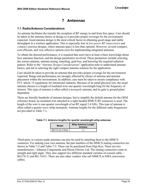
There are literally hundreds of antenna designs, but to simplify the default antenna for the OEM<br />
reference board, an insulated wire attached to a right handed MMCX RF connector is used. The<br />
length of the wire is one-quarter wavelength of an RF signal 2.4 GHz. This type of antenna is<br />
often called a quarter wave whip monopole. Antenna lengths for the different radio frequencies<br />
are provided in Table 7-1.<br />
Table 7-1. Antenna lengths for quarter wavelength whip antennas<br />
Model<br />
Whip Antenna Length<br />
(inches)<br />
<strong>M2110</strong> (2.4 GHz) 1.2<br />
Third-party or custom made antennas can also be used by attaching them to the MMCX<br />
connector. For making your own antenna, the part numbers of the MMCX mating connectors are<br />
shown in Table 7-2 and Table 7-3. These can be purchased from Digi-Key. There are two<br />
manufacturers—Johnson Components and Hirose Electric Ltd. The mating connectors come in<br />
straight and right angle. They also support two different standard varieties of coaxial cable—<br />
RG178 /U and RG 316/U. There are also other vendors who sell MMCX to SMA conversion<br />
cables.<br />
Doc. # 7430-0549-01 Rev. A Page 25