Intel® Desktop Board DH61CR Product Guide
Intel® Desktop Board DH61CR Product Guide
Intel® Desktop Board DH61CR Product Guide

Create successful ePaper yourself
Turn your PDF publications into a flip-book with our unique Google optimized e-Paper software.
Intel <strong>Desktop</strong> <strong>Board</strong> <strong>DH61CR</strong> <strong>Product</strong> <strong>Guide</strong><br />
Front Panel Header<br />
46<br />
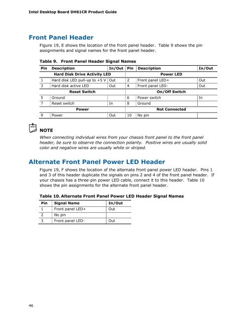
Figure 19, E shows the location of the front panel header. Table 9 shows the pin<br />
assignments and signal names for the front panel header.<br />
Table 9. Front Panel Header Signal Names<br />
Pin Description In/Out Pin Description In/Out<br />
Hard Disk Drive Activity LED Power LED<br />
1 Hard disk LED pull-up to +5 V Out 2 Front panel LED+ Out<br />
3 Hard disk active LED Out 4 Front panel LED- Out<br />
Reset Switch On/Off Switch<br />
5 Ground 6 Power switch In<br />
7 Reset switch In 8 Ground<br />
Power Not Connected<br />
9 Power Out 10 No pin<br />
NOTE<br />
When connecting individual wires from your chassis front panel to the front panel<br />
header, be sure to observe the connection polarity. Positive wires are usually solid<br />
color and negative wires are usually white or striped.<br />
Alternate Front Panel Power LED Header<br />
Figure 19, F shows the location of the alternate front panel power LED header. Pins 1<br />
and 3 of this header duplicate the signals on pins 2 and 4 of the front panel header. If<br />
your chassis has a three-pin power LED cable, connect it to this header. Table 10<br />
shows the pin assignments for the alternate front panel header.<br />
Table 10. Alternate Front Panel Power LED Header Signal Names<br />
Pin Signal Name In/Out<br />
1 Front panel LED+ Out<br />
2 No pin<br />
3 Front panel LED- Out