


Create successful ePaper yourself
Turn your PDF publications into a flip-book with our unique Google optimized e-Paper software.
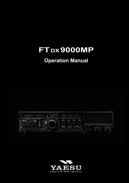
FT DX<strong>9000MP</strong><br />
Operation Manual
FT DX <strong>9000MP</strong> OPERATION MANUAL<br />
GENERAL DESCRIPTION<br />
We wish to take this opportunity to thank you for your purchase of the FT DX <strong>9000MP</strong> Transceiver!<br />
The FT DX <strong>9000MP</strong> is the culmination of a four-year design project. But it also is the product of our company’s fifty years<br />
of engineering, design, and manufacturing know how. As pioneers in the development of SSB, we have led the technological<br />
advances in Amateur Radio communications over the last half century. And now, with the introduction of the FT DX<br />
<strong>9000MP</strong>, we again lead the way with a no-compromise 21st-century design that will make your operating dreams come<br />
true. More importantly, it is a radio that will let your skills and experience find expression, as you harness the excitement of<br />
HF operating like you’ve never done before!<br />
ABOUT THIS MANUAL . . .<br />
The FT DX <strong>9000MP</strong> is a leading-edge transceiver with a number of new and exciting features, some of which may be<br />
unfamiliar to you. In order to gain the most enjoyment and operating efficiency from your FT DX <strong>9000MP</strong>, we recommend<br />
that you read this manual in its entirety, and keep it handy for reference as you explore the many capabilities of your new<br />
transceiver.<br />
Before using your FT DX <strong>9000MP</strong>, be sure to read and follow the instructions in the “Before You Begin” section of this<br />
manual.<br />
CONVENTIONS USED IN THIS MANUAL<br />
Please note the conventions, described below, for operational commands and texts included in this manual.<br />
(# ) ..... This refers to a switch or knob used for controlling a particular function. The name or number inside the<br />
brackets designate the name of the switch/knob, or its reference number within this manual<br />
.............. This is the name of a switch or knob.<br />
XX ........... In the texts, you may be advised to press a button momentarily, or press and hold it in for a time interval (such<br />
as two seconds). Please be sure to observe the proper procedure when pressing a button.<br />
OO ........... This indicates the pressing of a button when a “momentary” press is the only selection available.<br />
Note .............................................. This is used for a note as to a particular point of interest.<br />
Advice .......................................... This is used to amplify or expand on instructions, so as to recommend a way to gain<br />
maximum benefit from a feature or function.<br />
Example ....................................... This is used to demonstrate an example of how a feature or function should work or<br />
be programmed.<br />
Quick Note / Quick Point ..... This is used for a brief explanation of a particular aspect of operation.<br />
Terminology ................................ An explanation of a term or expression used in this manual.<br />
This device is designed for Amateur Radio operation only. Operation on the Amateur Radio bands requires a license, in<br />
accordance with the telecommunications statutes in your country. The discussions in this manual presume that you possess<br />
the fundamental knowledge consistent with your status as a licensed Amateur Radio operator.<br />
Page 1
TABLE OF CONTENTS<br />
General Description ............................................. 1<br />
About This Manual. . . ............................................................. 1<br />
Conventions Used in This Manual .......................................... 1<br />
Before You Begin. . . ............................................ 4<br />
1. Connecting AC Power ......................................................... 4<br />
2. Configuring Your FT DX 9000 Using the Menu ................ 4<br />
3. Connecting and Selecting the Microphone ......................... 5<br />
4. Extending the Front Feet ..................................................... 5<br />
5. Adjusting the Main Dial Torque .......................................... 6<br />
6. Restarting Power after a Voltage Fluctuation ...................... 6<br />
7. Resetting the Microprocessor .............................................. 7<br />
Resetting Memories (Only) ............................................... 7<br />
Menu Resetting ................................................................. 7<br />
Full Reset .......................................................................... 7<br />
Features ................................................................ 8<br />
Accessories ........................................................ 10<br />
Options ............................................................... 11<br />
Installation and Interconnections..................... 12<br />
Antenna Considerations ........................................................ 12<br />
About Coaxial Cable ............................................................. 12<br />
Grounding .............................................................................. 13<br />
Antenna and FPS-9000H Power Supply Connections .......... 14<br />
Connection of Microphone, Headphones,<br />
and FH-2 Remote Control Keypad ........................................ 15<br />
Key, Keyer, and Computer-Driven Keying Interconnections 16<br />
Connecting a GPS Receiver .................................................. 16<br />
VL-1000 Linear Amplifier Interconnections ......................... 17<br />
Interfacing to Other Linear Amplifiers .................................. 18<br />
Plug/Connector Pinout Diagrams .................... 19<br />
Front Panel Controls ......................................... 20<br />
Rear Panel ..........................................................36<br />
FPS-9000H Front Panel Controls ..................... 40<br />
FPS-9000H Rear Panel ....................................... 41<br />
Frequency Display ............................................. 39<br />
FH-2 Operation ................................................... 42<br />
Basic Operation:<br />
Receiving on Amateur Bands ........................... 43<br />
Operation ............................................................................... 43<br />
Operation on 60-Meter (5 MHz) Band (U.S. version only) .. 46<br />
CLAR (Clarifier) Operation on Main (VFO-A) .................... 47<br />
LOCK .................................................................................... 48<br />
DIM ....................................................................................... 48<br />
B-DISP OFF .......................................................................... 49<br />
Convenient Features ......................................... 50<br />
Dual Receive ......................................................................... 50<br />
Dual Receive: Full Duplex Operation ................................... 51<br />
P.BACK (Audio Playback) from Main (VFO-A) Receiver ... 54<br />
“My Bands” Operation .......................................................... 55<br />
Band Stack Operation ............................................................ 56<br />
C.S (Custom Switch) ............................................................. 56<br />
Dial Swap Configuration (AF/RF GAIN controls) ............... 57<br />
Data Management Feature ..................................................... 58<br />
More Frequency Navigation Techniques ............................... 59<br />
Antenna Selection .................................................................. 60<br />
Changing the Speaker Output Configuration ........................ 61<br />
Receiver Operation (Front End Block Diagram)................... 62<br />
IPO (Intercept Point Optimization) ....................................... 63<br />
ATT ........................................................................................ 64<br />
RF Gain (SSB/CW/AM Modes) ............................................ 65<br />
Advanced Interference-<br />
Suppression Features ....................................... 66<br />
Using the VRF (Variable RF Front-end Filter) ..................... 66<br />
Interference Rejection ....................................... 67<br />
R.FLT (Roofing Filters) ......................................................... 67<br />
CONT (Contour) Control Operation ..................................... 68<br />
IF SHIFT Operation (SSB/CW/RTTY/PKT/AM Modes) ..................... 69<br />
WIDTH (IF DSP Bandwidth) Tuning (SSB/CW/RTTY/PKT Modes) ......... 70<br />
Using IF Shift and Width Together ................................. 71<br />
IF Notch Filter Operation (SSB/CW/RTTY/PKT/AM Modes) ............. 72<br />
Digital Noise Reduction (DNR) Operation ........................... 73<br />
NARROW (NAR) One-Touch IF Filter Selection ................ 74<br />
Digital Notch Filter (DNF) Operation ................................... 75<br />
IF Noise Blanke (NB) Operation........................................... 76<br />
Tools for Comfortable and<br />
Effective Reception.................... 77<br />
AGC (Automatic Gain Control) ............................................ 77<br />
SLOPED AGC Operation ............................................... 78<br />
Mute Feature Main (VFO-A) Band ...................................... 79<br />
Audio Limiter (AFL) Feature ................................................ 79<br />
Adjacent Channel Monitor (ACM) (CW Mode Only) .......... 80<br />
Audio Filter Operation .......................................................... 81<br />
Page 2 FT DX <strong>9000MP</strong> OPERATION MANUAL
SSB/AM Mode Transmission<br />
(Let's Look at the Transmitter. . .).....................82<br />
Phantom Voltage for Condenser Microphones ...................... 83<br />
Using the Automatic Antenna Tuner ................84<br />
ATU Operation ...................................................................... 84<br />
About ATU Operation............................................................ 85<br />
Lithium Battery Replacement ................................................ 86<br />
SSB/AM Mode Transmission ............................87<br />
Using the Speech Processor (SSB, AM Mode) ..................... 87<br />
Adjusting the SSB Transmitted Bandwidth ........................... 89<br />
Signal Quality Enhancement Using the<br />
Parametric Microphone Equalizer ......................................... 90<br />
Low- Distortion CLASS-A Operation ................................... 92<br />
Voice Memory ....................................................................... 94<br />
Convenient Transmitter Accessories ...............96<br />
VOX: Automatic TX/RX Switching using Voice Control<br />
(SSB/AM/FM Modes) ........................................................... 96<br />
Using the MONITOR ............................................................ 96<br />
Split Operation Using the TX Clarifier (VFO-A Operation) ......... 97<br />
Clarifier Offset Bar Indicator .......................................... 97<br />
Split-Frequency Operation .................................................... 98<br />
Quick Split Operation ..................................................... 99<br />
Full Duplex Operation ......................................................... 100<br />
CW Mode Operation ........................................102<br />
Setup for Straight Key (and Straight Key emulation) Operation ...... 101<br />
Using the Built-in Electronic Keyer .................................... 103<br />
Full Break-in (QSK) Operation..................................... 103<br />
Setting the Keyer Weight (Dot/Space:Dash ) Ratio ...... 104<br />
Selecting the Keyer Operating Mode ............................ 104<br />
CW Convenience Features ............................. 105<br />
CW Spotting (Zero-Beating) ............................................... 105<br />
Using CW Reverse .............................................................. 106<br />
CW Delay Time Setting ....................................................... 107<br />
CW Pitch Adjustment .......................................................... 107<br />
Contest Memory Keyer ....................................................... 108<br />
Message Memory .......................................................... 108<br />
TEXT Memory .............................................................. 110<br />
FM Mode Operation ......................................... 112<br />
Operation ............................................................................. 112<br />
Repeater Operation .............................................................. 113<br />
FT DX <strong>9000MP</strong> OPERATION MANUAL<br />
TABLE OF CONTENTS<br />
Convenient Memory Functions ...................... 114<br />
QMB (Quick Memory Bank) ............................ 115<br />
QMB Channel Storage ........................................................ 115<br />
QMB Channel Recall .......................................................... 115<br />
Memory Groups ............................................... 116<br />
Memory Group Assignment ................................................ 116<br />
Choosing the Desired Memory Group ................................ 116<br />
Memory Operation ........................................... 117<br />
Memory Storage .................................................................. 117<br />
Memory Channel Recall ...................................................... 117<br />
Checking a Memory Channel’s Status .......................... 118<br />
Erasing Memory Channel Data ........................................... 118<br />
Moving Memory Data to the Main (VFO-A) Band ............ 119<br />
Memory Tune Operation ............................................... 119<br />
Operation on Alaska Emergency Frequency:<br />
5167.5 kHz (U.S. Version Only) ....................... 120<br />
Operation on the 60-Meter Band (U.S. Version) .. 121<br />
VFO and Memory Scanning ............................122<br />
VFO Scanning ..................................................................... 122<br />
Memory Scan ....................................................................... 122<br />
PMS ................................................................... 123<br />
Packet Operation ............................................. 124<br />
RTTY (Radio TeleType) Operation .................. 125<br />
Miscellaneous AFSK-based Data Modes .......126<br />
About the Transverter Output Terminal ......... 127<br />
Menu Mode .......................................................128<br />
Using the Menu ................................................................... 128<br />
Menu Mode Reset ......................................................... 128<br />
Menu Mode Setting Table ................................................... 129<br />
Menu Mode Setting ............................................................. 133<br />
Customized Option .......................................... 149<br />
About Customization Options ............................................. 149<br />
RF µ-Tuning Unit (MTU-160, MTU-80/40, MTU-30/20) .... 150<br />
TFT Display Unit (TFT-9000) ................................ 152<br />
Specifications ................................................... 156<br />
Page 3
Before You Begin. . .<br />
1. Connecting AC Power<br />
There are two power switches on this transceiver, one each on the rear and front panels. If the rear panel’s Power switch is<br />
not turned on, the front panel Power switch will not function.<br />
❒ Push the Power switch on the<br />
FPS-9000H to the I position<br />
to apply power from the power<br />
supply to the transceiver’s<br />
OCXO (Reference Crystal Oven)<br />
and to enable the front panel<br />
power switch.<br />
❒ Press and hold in the front panel<br />
Power switch for two seconds to<br />
turn the transceiver on.<br />
☞<br />
Note<br />
The self-check function of the CPU inside the radio will<br />
begin.<br />
If the optional RF µ-Tuning Unit is installed, the µ-Tuning<br />
circuitry will receive the data from the CPU, and it<br />
will perform its own self-check, and will preset itself to<br />
the proper settings for the current operating frequency.<br />
While the µ-Tuning circuitry is obtaining the data, the drive<br />
mechanism will move from one end of its range to the<br />
other end (fast), and this will cause a temporary “motor”<br />
noise that can be heard; this, does not represent any trouble<br />
or problem.<br />
When the radio is turned on for the first time, it takes about<br />
50 seconds (from turning the radio on to completing the<br />
self-check) until the radio becomes ready to use; however,<br />
from the next time you turn it on, it will take around<br />
10 seconds until the transceiver is ready for full operation.<br />
2. Configuring Your FT DX <strong>9000MP</strong> Using the Menu<br />
The FT DX <strong>9000MP</strong> is configured, at the factory, with its various functions set up in a manner typical for most operation. Via<br />
the “Menu” system, you may change these settings to match the way you want your transceiver to operate.<br />
Menu programming is enabled by pressing the MNU (Menu) key momentarily. You may then rotate the Main Tuning<br />
Dial to display the desired Menu item, in the menu list, on the LCD display. Each of the settings can be changed or<br />
customized via the CLAR/VFO-B knob, as you like, in this mode.<br />
Once you have made a change to the configuration of a<br />
Menu item or items, you must press and hold in the<br />
MNU (Menu) key for two seconds to save the new settings<br />
and exit to normal operation.<br />
If you wish to cancel a change to a Menu item or items,<br />
just press the MNU key momentarily. If you do not press<br />
and hold in the MNU key in for two seconds, any changes<br />
you have made will not be saved.<br />
Main Tuning Dial<br />
LCD Display<br />
Menu Item<br />
Menu Setting<br />
MNU Key<br />
CLAR/VFO-B Knob<br />
Page 4 FT DX <strong>9000MP</strong> OPERATION MANUAL
3. Connecting and Selecting the Microphone<br />
The FT DX <strong>9000MP</strong> comes equipped with two microphone connectors: the front panel includes a “Cannon” (XLR) threepin<br />
connector, while the rear panel provides an eight-pin (round) connector.<br />
As shipped from the factory, the front panel XLR connector is engaged for operation, and the rear panel 8-pin microphone<br />
jack is not connected. If you wish to enable the 8-pin connector instead of the XLR connector, use the Menu to accomplish<br />
this. Note that you may leave microphones connected to both jacks, and may select the microphone you want for operation<br />
on a particular operating mode (SSB, AM, FM, etc.), as well!<br />
❒ Press the MNU (Menu) key momentarily to enter<br />
the Menu Mode.<br />
❒ Rotate the Main Tuning Dial to select Menu Item<br />
#069, located within the “MODE SSB” group: SSB<br />
MIC SELECT.<br />
❒ Rotate the CLAR/VFO-B knob to change the setting<br />
of Menu #069 from “FRONT” to “REAR.”<br />
❒ Press and hold in the MNU (Menu) key for two seconds<br />
to save the new setting and exit to normal operation.<br />
❒ In a similar manner, you may use Menu #040 (AM<br />
MIC SEL) in the MODE-AM Menu Group to select<br />
the microphone jack to be used during AM operation,<br />
and Menu #059 (FM MIC SEL) in the MODE-FM<br />
Menu Group to select the microphone to be used during<br />
FM transmission.<br />
4. Extending the Front Feet<br />
In order to elevate the front panel for easy viewing, the front left and right feet of the bottom case may be extended.<br />
❒ Pull the front legs outward from the bottom panel.<br />
❒ Rotate the legs counter-clockwise to lock them in the<br />
extended position. Be sure the legs have locked securely<br />
in place, because the transceiver is quite heavy<br />
and an unlocked leg could result in damage, should<br />
the transceiver move suddenly.<br />
Retracting the Front Feet<br />
❒ Rotate the legs clockwise, and push them inward while<br />
rotating to the right.<br />
❒ The front feel should now be locked in the retracted<br />
position.<br />
FT DX <strong>9000MP</strong> OPERATION MANUAL<br />
Before You Begin. . .<br />
“FRONT”<br />
Cannon (XLR)<br />
3-pin connector<br />
➀<br />
➁<br />
➀<br />
➁<br />
Main Tuning Dial<br />
“REAR”<br />
8-pin microphone jack<br />
EXTEND<br />
RETRACT<br />
MNU Key<br />
CLAR/VFO-B Knob<br />
Page 5
Before You Begin. . .<br />
5. Adjusting the Main Dial Torque<br />
The torque (drag) of the Main Tuning Dial may be adjusted according to your preferences. Simply hold down the rear skirt<br />
of the knob, and while holding it in place rotate the Main Dial itself to the right to reduce the drag, or to the left to increase<br />
the drag.<br />
TIGHTEN TOOSEN<br />
HOLD THE SKIRT<br />
6. Restarting Power after a Voltage Fluctuation<br />
If your AC mains power should suffer a significant fluctuation or interruption, we recommend that<br />
you go through a complete power-up cycle, in order to ensure that all circuits are properly initialized.<br />
To do this, be sure the front panel Power switch is turned off, then set the FPS-9000H’s Power switch<br />
to the “O” position. Now unplug the AC cable from the rear panel of the FPS-9000H, and wait ten<br />
seconds. Plug the AC cable back in, set the FPS-9000H’s Power switch to “O,” and now press and<br />
hold in the front-panel Power switch for two seconds to turn the transceiver on. After about 50 seconds,<br />
all circuits wil be initialized, and normal operation may resume.<br />
Page 6 FT DX <strong>9000MP</strong> OPERATION MANUAL
Before You Begin. . .<br />
7. Resetting the Microprocessor<br />
❐ Resetting Memories (Only)<br />
Use this procedure to reset (clear out) the Memory channels previously stored, without affecting any configuration changes<br />
you may have made to the Menu settings.<br />
1. Press the front panel’s POWER switch to turn the<br />
transceiver off.<br />
2. Press and hold in the A M switch; while holding<br />
it in, press and hold in the front panel’s POWER<br />
switch to turn the transceiver on. Once the transceiver<br />
comes on, you may release the A M switch.<br />
❐ Menu Resetting<br />
Use this procedure to restore the Menu settings to their factory defaults, without affecting the memories you have programmed.<br />
1. Press the front panel’s POWER switch to turn the<br />
transceiver off.<br />
2. Press and hold in the MNU (Menu) key; while holding<br />
it in, press and hold in the front panel’s POWER<br />
switch to turn the transceiver on. Once the transceiver<br />
comes on, you may release the MNU (Menu) key.<br />
❐ Full Reset<br />
Use this procedure to restore all Menu and Memory settings to their original factory defaults. All Memories will be cleared<br />
out by this procedure.<br />
1. Press the front panel’s POWER switch to turn the<br />
transceiver off.<br />
2. Press and hold in the FAST and LOCK switches;<br />
while holding them in, press and hold in the front<br />
panel’s POWER switch to turn the transceiver on.<br />
Once the transceiver comes on, you may release the<br />
other two switches. POWER Switch<br />
FAST Switch<br />
&<br />
LOCK Switch<br />
FT DX <strong>9000MP</strong> OPERATION MANUAL<br />
POWER Switch<br />
POWER Switch<br />
A M Switch<br />
MMU Key<br />
Page 7
FEATURES<br />
Superior Visibility and Logical, Fatigue-reducing Panel Layout<br />
The front panel layout is logically crafted, with the large-aperture main frequency display squarely in the middle of the front panel; the<br />
two large S-meters to the left providing instant recognition of signal strength.<br />
Just as in an aircraft cockpit, the panel meters and the LCD display are canted slightly toward the center for maximum visibility.<br />
Large, Multi-colored VFD Fluorescent Display<br />
A proprietary, high-brightness VFD (fluorescent) display is incorporated in the FT DX <strong>9000MP</strong>, providing outstanding visibility and easy<br />
reading of the important frequency information, whether in dim or bright lighting environments.<br />
Function-Indicating LEDs<br />
The many function status indications on the front panel are clearly identified by the operator, thanks to the innovative multi-color LEDs<br />
incorporated in design. A Red LED indicates that a function is engaged on the Main Band, while an Orange LED shows that the function<br />
is engaged on the Sub Band.<br />
Indirect Illumination<br />
For ease of nighttime operation, the controls on the front panel are indirectly illuminated, thanks to carefully-positioned lamps in the<br />
frame underneath the meters and the Band switch.<br />
Aluminum-Die-Cast Oversized Main Tuning Dial<br />
The Main Tuning Dial is a large-diameter (3.2”/81 mm) dial directly coupled to the magnetic rotary encoder which drives the HRDDS<br />
via microprocessor control. Its heavy weight (7 oz./200 g) and quality mounting and construction provide a smooth “flywheel” effect<br />
during operation, ideal for quick cruising up and down a band.<br />
Oversized Knobs for Most Important Functions<br />
The concentric AF/RF Gain, SHIFT/WIDTH, and CLAR/VFO-B knobs are conveniently located at the right-bottom side of the Front<br />
Panel, for ease of access to these important controls.<br />
World’s First 400 MHz HRDDS Local Oscillator<br />
So as to optimize spurious-free dynamic range in a multi-signal environment, <strong>Yaesu</strong>’s engineers have introduced the world’s first<br />
HRDDS (High Resolution Direct Digital Synthesizer) as the first local oscillator of the FT DX <strong>9000MP</strong>. Dividing directly from this high<br />
frequency, this local oscillator design ensures extraordinarily low noise, resulting in improved weak-signal reception even on a crowded<br />
band during a weekend contest.<br />
New-design Large-area OCXO Reference Oscillator<br />
Serving as the master reference oscillator for the transceiver, the 10 MHz OCXO (Oven Controlled Crystal Oscillator) is a large-area (50<br />
x 50 mm/2” x 2”) oven-stabilized oscillator operating at high temperature, for industry-leading frequency stability rated at 0.03 ppm<br />
over the temperature range –10° to +60° C (–14° to +140° F).<br />
Triple-conversion Design with Optimized Gain Distribution<br />
Taking into account the most efficient transceiver design concept consistent with high performance we have adopted a triple-conversion<br />
IF structure, utilizing a first IF at 40 MHz, a second IF at 455 kHz, and the third IF at 30 kHz (for FM, the 3rd IF is at 24 kHz). Gain<br />
distribution through all stages is carefully optimized, for preservation of high system dynamic range.<br />
Ultra-strong Receiver Front End<br />
YAESU’s outstanding RF-stage filtering establishes a clean performance that allows the rest of the receiver to perform at a high level. By<br />
reducing the ingress of energy from very strong sources like Shortwave Broadcast, local AM/FM/TV stations, and other signal sources,<br />
the overall purity of the spectrum delivered to the RF Amplifier first mixer, and subsequent stages is maintained, and the system<br />
Blocking Dynamic Range is also enhanced.<br />
Compact Flash (CF) Card for Data Management<br />
A Compact Flash card is supplied with every FT DX <strong>9000MP</strong>, for preservation of transceiver configuration settings along with Log Book<br />
archival data.<br />
Professional-Grade Cannon (XLR) Microphone Connector<br />
The FT DX <strong>9000MP</strong> incorporates, for the first time ever in an Amateur Radio transceiver, a balanced-input “Cannon” (XLR) microphone<br />
connector on the front panel, for use with studio-grade professional microphones. A round 8-pin microphone jack is also provided on the<br />
rear panel.<br />
Two High-precision Analog Meters (Page 27)<br />
The FT DX <strong>9000MP</strong> incorporates two large (3.4”/86 mm) high-precision analog meters, for the utmost accuracy in measuring transceiver<br />
performance. Visibility is enhanced by the oversized meter scales, making the meters easy to read at all times.<br />
Separated Clarifier Display (Pages 47, 97)<br />
A clearly-separated display window within the main frequency display area contains receiver and/or transmitter frequency offset (“Clarifier”)<br />
data, for quick comprehension by the operator.<br />
YAESU Custom-designed 32-Bit Floating Point IF DSP (Page 62)<br />
The new IF DSP system, utilizing a TI TMS320C6711 device, is a high-speed 32-bit floating point circuit designed with a unique<br />
objective: to do away with the “digital” sound of many DSP filtering systems, and emulate the “Analog Sound” so familiar and comfortable<br />
to HF DX and Contest operators. The result is a leading-edge receiver that has the “feel” of a traditional analog receiver, but with<br />
the flexibility and superb filtering capability of a modern digital filtering system.<br />
Page 8 FT DX <strong>9000MP</strong> OPERATION MANUAL
FT DX <strong>9000MP</strong> OPERATION MANUAL<br />
FEATURES<br />
VRF (Variable RF Filter) Preselector Filter (Page 66)<br />
<strong>Yaesu</strong>’s robust VRF (Variable RF Filter) preselector provides a relay-selected RF selectivity much tighter than that afforded by traditional<br />
bandpass filter networks. Sealed relays select heavy-duty inductors and capacitors, providing a tracking RF filter that protects the<br />
RF amplifier and following stages from strong out-of-band energy.<br />
First IF 3 kHz Roofing Filter (Page 24, 67)<br />
In the 40 MHz 1st IF, three selectable roofing filters are provided, in bandwidths of 3 kHz, 6 kHz, and 15 kHz, to protect the following<br />
stages from strong signals that could degrade dynamic range in the first IF amplifier and subsequent stages. The roofing filters are<br />
automatically assigned according to the operating mode, but the operator may override the automatic selections on the fly.<br />
CONTOUR Filter Enhances “Analog Feeling” of DSP Filters (Page 29, 68)<br />
The DSP-based Contour system is a unique five-band filter that may be used to roll off or peak the IF response. It is chiefly useful for<br />
modifying the response of the ultra-sharp DSP filters, allowing you to roll off (or emphasize) certain frequency components. Oftentimes,<br />
the result is that a difficult-to-understand signal suddenly will pop out of the background noise as solid copy.<br />
SLOPED AGC Circuitry (Page 78)<br />
In traditional AGC systems, all signals rising above a certain RF level are then clamped together at the same audio output, so as to<br />
prevent distortion throughout the IF and AF stages. In the FT DX <strong>9000MP</strong>, however, you can engage the “Sloped” AGC capability to<br />
provide an AGC response whereby ever-increasing signal strength results in a slightly-louder audio response, still without accompanying<br />
distortion. This lets you use your brain to sort out weak signals from strong ones more effectively.<br />
Receiver AF Limiter Circuit (Page 32, 79)<br />
Occasionally a noise burst or a sudden transmission from a loud station may startle you if you have the AF Gain turned up, and may even<br />
damage your hearing temporarily. The FT DX <strong>9000MP</strong> provides an AF Limiter (AFL) circuit which, once engaged, clamps an upper limit<br />
on the available audio output power, much like the AGC circuit does in the RF and IF stages.<br />
“Adjacent Channel Encroachment” S-Meter Monitor (Page 33, 80)<br />
When operating CW in a narrow bandwidth like 300 Hz, you may not be aware of the presense of strong stations that may be making it<br />
difficult for others to hear you. In these situations, the “ACM” (Adjacent Channel Monitor) will take over the Sub Receiver, center it on<br />
the Main Receiver frequency, and display ± 1.2 kHz of signal activity on the Sub Receiver’s S-meter (without feeding the interfering<br />
audio through). This alerts you to the situation, and you can QSY or ask the other station to QSY.<br />
Rugged, High-Output Final Amplifier Design (Page 93)<br />
The final amplifier stage of the FT DX <strong>9000MP</strong> utilizes parallel push-pull SD2931 MOS FET devices in a conservative, high-stability<br />
design. The large-area die-cast aluminum heat sink is monitored thermostatically, and a quiet cooling fan will engage when the heat sink<br />
temperature rises during long periods of high-power transmission.<br />
Ultra-linear Class-A Operation Capability (Page 92)<br />
The FT DX <strong>9000MP</strong>’s Class-A capability provides ultra-linear amplifier operation at 100 Watts of power output. Typically, 3rd-order<br />
IMD products are suppressed more than 50 dB, while 5th- and higher-order distortion products are at least 70 dB down during Class-A<br />
operation.<br />
Parametric Microphone Equalizer Circuit (Page 90)<br />
For unmatched flexibility in tailoring your microphone’s audio to match your voice, <strong>Yaesu</strong>’s engineers have incorporated the industry’s<br />
first Three-Band Parametric Microphone Equalizer, which allows you to enhance or suppress frequency components in three different<br />
audio bands. Equalization may be applied independently to microphones attached to the front and rear panel microphone jacks.<br />
Connecting Your After-market Computer Monitor for Multiple Function Displays<br />
(Refer to the separate Data Management Unit Operating Manual)<br />
Connection of your after-market computer monitor (not supplied) allows display of a number of important and useful operating status<br />
and function displays. These include the Menu mode, World Clock, Spectrum Scope, Audio Scope and Oscilloscope, Logbook, Temperature/SWR<br />
monitoring, Rotator Control, and Memory Channel listings.<br />
Customization of Your FT DX <strong>9000MP</strong><br />
A wide range of custom configuration options (other than a better location or taller tower!) are available for your FT DX <strong>9000MP</strong>,<br />
allowing you to build a Dream Station from the “MP” version foundation.<br />
Because these options involve high-technology modules, please consult WDXC regarding factory installation of these items.<br />
❒ RF µ-Tuning Units (MTU-160, MTU-80/40, MTU-30/20)<br />
On the 14 MHz and lower bands, the µ-Tuning Units provide extraordinarily high Q; the resulting steep shape factor is a powerful<br />
aid for reducing off-frequency interference. Separate modules are available for the 1.8 MHz, 3.5/7 MHz, and 10.1/14 MHz bands,<br />
and they may be installed on the Main Receiver only (not in the Sub Receiver).<br />
Thanks to the large (1.1”/28 mm) inductor through which a stack of ferrite cores is adjusted, the narrow RF bandwidth of the µ-<br />
Tuning System provides unmatched protection for the receiver front end and following circuits.<br />
❒ TFT Display Unit (TFT-9000)<br />
The TFT-9000 TFT Display Unit allows to display the enable the “World Clock,” “Spectrum Scope,” “Audio Scope/Oscilloscope,”<br />
“Logbook,” “Rotator Control,” and “Temperature/SWR Status Display” functions to the internal 6.5” TFT Display, which provides 800<br />
x 480 dot screen high resolution and easy viewing.<br />
Page 9
ACCESSORIES<br />
FPS-9000H<br />
External Power Supply<br />
with Dual Speakers and<br />
Audio Filters<br />
Piugs<br />
RCA Plug (P0091365)<br />
6 pcs<br />
SUPPLIED ACCESSORIES<br />
FH-2<br />
Remote Control Keypad<br />
❍ Operating Manual<br />
❍ Warranty Card<br />
1/4-inch 3-contact Plug<br />
(P0090008)<br />
2 pcs<br />
CF Card<br />
(64 MB: Q9000838)<br />
Plug Details and Part Numbers<br />
3.5 mm 2-contact Plug<br />
(P0090034)<br />
2 pcs<br />
Items are shown for illustrative purposes only, and may vary slightly in appearance.<br />
AC Power Cord 1<br />
Microphone Extend Cable<br />
(8 Pin Modular) 2<br />
1: AC Power Cord<br />
USA: T9017882<br />
Europe: T9013285<br />
Australia: T9013283A<br />
UK: T9013285<br />
2: This microphone cable is for use with the optional<br />
MD-200A8X, MD-100A8X, or MH-31B8 microphones.<br />
3.5 mm 3-contact Plug<br />
(P0091046)<br />
1 pc<br />
4-pin DIN Plug (P0091004) 1 pc<br />
5-pin DIN Plug (P0091006) 1 pc<br />
7-pin DIN Plug (P0091419) 1 pc<br />
8-pin DIN Plug (P0090651) 1 pc<br />
Page 10 FT DX <strong>9000MP</strong> OPERATION MANUAL
MD-200A8X<br />
Ultra-High-Fidelity Desk-Top Microphone<br />
MD-200A8X<br />
Desk-Top Microphone<br />
MD-100A8X<br />
Linear Amplifier / AC Power Supply<br />
VL-1000 / VP-1000<br />
FT DX <strong>9000MP</strong> OPERATION MANUAL<br />
AVAILABLE OPTIONS<br />
Customization Options<br />
❍ RF µ-Tuning Unit A MTU-160 (160 m Band)<br />
❍ RF µ-Tuning Unit B MTU-80/40 (80/40 m Bands)<br />
❍ RF µ-Tuning Unit C MTU-30/20 (30/20 m Bands)<br />
❍ TFT Display Unit TFT-9000<br />
OPTIONS<br />
Lightweight Stereo Headhones<br />
YH-77STA<br />
Page 11
INSTALLATION AND INTERCONNECTIONS<br />
ANTENNA CONSIDERATIONS<br />
The FT DX <strong>9000MP</strong> is designed for use with any antenna system providing a 50 Ohm resistive impedance at the desired<br />
operating frequency. While minor excursions from the 50-Ohm specification are of no consequence, the transceiver’s<br />
Automatic Antenna Tuner may not be able to reduce the impedance mismatch to an acceptable value if the Standing Wave<br />
Ratio (SWR) present at the Antenna jack is greater than 3:1.<br />
Every effort should, therefore, be made to ensure that the impedance of the antenna system utilized with the FT DX <strong>9000MP</strong><br />
be as close as possible to the specified 50-Ohm value.<br />
Any antenna to be used with the FT DX <strong>9000MP</strong> must, ultimately, be fed with 50 Ohm coaxial cable. Therefore, when using<br />
a “balanced” antenna such as a dipole, remember that a balun or other matching/balancing device must be used so as to<br />
ensure proper antenna performance.<br />
The same precautions apply to any additional (receive-only) antennas connected to the RX ANT jack; if your receive-only<br />
antennas do not have an impedance near 50 Ohms at the operating frequency, you may need to install an external antenna<br />
tuner to obtain optimum performance.<br />
ABOUT COAXIAL CABLE<br />
Use high-quality 50-Ohm coaxial cable for the lead-in to your FT DX <strong>9000MP</strong> transceiver. All efforts at providing an<br />
efficient antenna system will be wasted if poor quality, lossy coaxial cable is used. This transceiver utilizes standard “M”<br />
(“PL-259”) type connectors, except for the “RX OUT” BNC connectors used for special filters, etc.<br />
1/16"<br />
3/4"<br />
1 1/8" 3/4''<br />
TYPICAL PL-259 INSTALLATION<br />
Adapter<br />
3/8'' 5/8''<br />
Page 12 FT DX <strong>9000MP</strong> OPERATION MANUAL<br />
1/8''
INSTALLATION AND INTERCONNECTIONS<br />
FT DX <strong>9000MP</strong> OPERATION MANUAL<br />
GROUNDING<br />
The FT DX <strong>9000MP</strong> HF transceiver, like any other HF communications apparatus, requires an effective ground system for<br />
maximum electrical safety and best communications effectiveness. A good ground system can contribute to station efficiency<br />
in a number of ways:<br />
❒ It can minimize the possibility of electrical shock to the operator.<br />
❒ It can minimize RF currents flowing on the shield of the coaxial cable and the chassis of the transceiver; such currents<br />
may lead to radiation which can cause interference to home entertainment devices or laboratory test equipment.<br />
❒ It can minimize the possibility of erratic transceiver/accessory operation caused by RF feedback and/or improper current<br />
flow through logic devices.<br />
An effective earth ground system make take several forms; for a more complete discussion, see an appropriate RF engineering<br />
text. The information below is intended only as a guideline.<br />
Typically, the ground connection consists of one or more copper-clad steel rods, driven into the ground. If multiple ground<br />
rods are used, they should be positioned in a “V” configuration, and bonded together at the apex of the “V” which is nearest<br />
the station location. Use a heavy, braided cable (such as the discarded shield from type RG-213 coaxial cable) and strong<br />
cable clamps to secure the braided cable(s) to the ground rods. Be sure to weatherproof the connections to ensure many<br />
years of reliable service. Use the same type of heavy, braided cable for the connections to the station ground bus (described<br />
below).<br />
Inside the station, a common ground bus consisting of a copper pipe of at least 25 mm (1”) diameter should be used. An<br />
alternative station ground bus may consist of a wide copper plate (single-sided circuit board material is ideal) secured to the<br />
bottom of the operating desk. Grounding connections from individual devices such as transceivers, power supplies, and<br />
data communications devices (TNCs, etc.) should be made directly to the ground bus using a heavy, braided cable.<br />
Do not make ground connections from one electrical device to another, and thence to the ground bus. This so-called “Daisy-<br />
Chain” grounding technique may nullify any attempt at effective radio frequency grounding. See the drawing below for<br />
examples of proper grounding techniques.<br />
Inspect the ground system - inside the station as well as outside - on a regular basis so as to ensure maximum performance<br />
and safety.<br />
Besides following the above guidelines carefully, note that household or industrial gas lines must never be used in an<br />
attempt to establish an electrical ground. Cold water pipes may, in some instances, help in the grounding effort, but gas lines<br />
represent a significant explosion hazard, and must never be used.<br />
Page 13
INSTALLATION AND INTERCONNECTIONS<br />
ANTENNA AND FPS-9000H POWER SUPPLY CONNECTIONS<br />
Please refer to the illustration for guidelines regarding connection of your antenna(s) and the FPS-9000H Power Supply.<br />
ANTENNA "1"<br />
ANTENNA "2"<br />
Use a short, thick, braided<br />
cable to connect your station<br />
equipment to the buried<br />
ground rod (or alternative<br />
earth ground system).<br />
Ground Rod<br />
ANTENNA "3"<br />
Advice<br />
● Do not position this apparatus in a location with direct<br />
exposure to sunshine.<br />
● Do not position this apparatus in a location exposed to<br />
dust and/or high humidity.<br />
● Ensure adequate ventilation around this apparatus, so<br />
as to prevent heat build-up and possible reduction of<br />
performance due to high heat.<br />
● Do not install this apparatus in a mechanically-unstable<br />
location, or where objects may fall onto this product<br />
from above.<br />
● To minimize the possibility of interference to home<br />
entertainment devices, take all precautionary steps including<br />
separation of TV/FM antennas from Amateur<br />
transmitting antennas to the greatest extent possible,<br />
and keep transmitting coaxial cables separated from<br />
cables connected to home entertainment devices.<br />
ANTENNA "4"<br />
EXT A<br />
EXT B<br />
Speaker スピーカーケーブル Cable (Supplied ( FPS-9000 with の the 付属品 FPS-9000H)<br />
)<br />
Speaker スピーカーケーブル Cable (Supplied ( FPS -9000 with の the 付属品 FPS-9000H)<br />
)<br />
Connect to the AC line outlet<br />
AC 100 V - AC 240 V<br />
FT DX <strong>9000MP</strong> FPS-9000H<br />
Page 14 FT DX <strong>9000MP</strong> OPERATION MANUAL<br />
B INPUT<br />
A INPUT<br />
Connect the OUTPUT Plug from<br />
the FPS-9000H to the DC IN Jack<br />
of the FT DX <strong>9000MP</strong><br />
● Ensure that the AC power cord is not subject to undue<br />
stress or bending, which could damage the cable or<br />
cause it to be accidentally unplugged from the rear panel<br />
AC input jack.<br />
● Be absolutely certain to install your transmitting<br />
antenna(s) such that they cannot possibly come in contact<br />
with TV/FM radio or other antennas, nor with outside<br />
power or telephone lines.<br />
Note<br />
Please be sure that both the transceiver’s front panel<br />
POWER switch and the FPS-9000H’s main power<br />
switch are both turned off any time you plug in or unplug<br />
any power cable to/from the FPS-9000H. This will avoid<br />
the possibility of potentially-damaging spikes and/or electrical<br />
shock.
CONNECTION OF MICROPHONE, HEADPHONES, AND FH-2 REMOTE CONTROL KEYPAD<br />
This transceiver was shipped from the factory in configuration for a microphone input via the Front Panel XLR<br />
connector. To use the Rear Panel microphone with an 8-pin round connector, please change the microphone set up<br />
via the Menu.<br />
1. To do this, first press the MNU key.<br />
2. The Menu list will appear on the LCD display screen.<br />
3. Rotate the Main tuning dial (VFO-A) to select menu item [MODE-SSB 069 SSB MIC SELECT].<br />
4. Now rotate the CLAR/VFO-B knob to change the setting to Rear.<br />
The available selections are FRONT-REAR-DATA-PC.<br />
5. To save the set-up, press and hold in the MNU key for 2 seconds.<br />
If the MNU key is not held for 2 seconds, the set-up will not be saved.<br />
Note : To use the AM or FM mode, please select Menu items 040 for AM and 059 for FM, and follow the same<br />
procedure above.<br />
② MIC-Hot<br />
③ MIC-Cold<br />
XLR connector Type Microhone<br />
INSTALLATION AND INTERCONNECTIONS<br />
① MIC-GND<br />
External After-market Monitor<br />
Note: If you plan to leave your transceiver<br />
and external monitor turned<br />
on for repeated, extended lengths<br />
of time, we recommend that you<br />
consider the use of a TFT monitor,<br />
which does not develop a “memory”<br />
of a particular display.<br />
FT DX <strong>9000MP</strong> OPERATION MANUAL<br />
LOCK<br />
ON OFF<br />
⑧ MIC<br />
① UP<br />
FH-2 Remote Control Keypad<br />
② +5V<br />
③ DOWN<br />
④ FAST<br />
1/4-inch 3-contact jack<br />
Stereo Headphones<br />
⑦ MIC GND<br />
⑥ PTT<br />
⑤ GND<br />
8-pin Connector Type Microphone<br />
Page 15
INSTALLATION AND INTERCONNECTIONS<br />
KEY, KEYER, AND COMPUTER-DRIVEN KEYING INTERCONNECTIONS<br />
The FT DX <strong>9000MP</strong> includes a host of features for the CW operator, the functions of which will be detailed in the “Operation”<br />
section later. Besides the built-in Electronic Keyer, two key jacks are provided, one each on the front and rear panels,<br />
for convenient connection to keying devices.<br />
The Menu system allows you to configure the front ane rear panel KEY jacks according to the device you wish to connect.<br />
For example, you may connect your keyer paddle to the front panel KEY jack, and use Menu #41 for paddle input, while<br />
connecting the rear panel’s KEY jack to the keying line from your personal computer (which emulates a “straight key” for<br />
connection purposes), and configure the rear panel jack using Menu #43.<br />
Both KEY jacks on the FT DX <strong>9000MP</strong> utilize “Positive” keying voltage. Key-up voltage is approximately +5V DC, and<br />
key-down current is approximately 1 mA.<br />
DOT DASH<br />
COMMON<br />
COMMON<br />
Advice<br />
When connecting a key or other device to the KEY jacks, use only a 3-pin (“stereo”) 1/4” phone plug; a 2-pin plug will<br />
place a short between the ring and (grounded) shaft of the plug, resulting in a constant “key-down” condition in some<br />
circumstances.<br />
If you connect a properly-equipped after-market GPS receiver<br />
(not supplied) to the COM port on the back of the<br />
transceiver, the “Rotator” page on the External display will<br />
automatically include a Great Circle map centered on your<br />
location.<br />
Connect a GPS receiver capable of output of NMEA-0183<br />
data to the COM port. The data line connects to Pin 2, and<br />
the ground shield connects to Pin 5.<br />
This transceiver can support the GGA, GLL, and RMC Data<br />
Sentences from the GPS unit.<br />
CONNECTING A GPS RECEIVER<br />
Pin 5<br />
GND<br />
Pin 2<br />
GPS DATA IN<br />
Page 16 FT DX <strong>9000MP</strong> OPERATION MANUAL<br />
DOT<br />
DASH
GND<br />
ANT 1<br />
50 MHz Antenna<br />
EXT ALC<br />
INSTALLATION AND INTERCONNECTIONS<br />
ANT 2<br />
VL-1000 LINEAR AMPLIFIER INTERCONNECTIONS<br />
Be sure that both the FT DX <strong>9000MP</strong> and VL-1000 are turned off, then follow the installation recommendations contained<br />
in the illustration.<br />
On the rear panel of the VL-1000, please set the “ATT” switch to the “ON” position, and set the maximum RF<br />
output power level to “200 W” via menu item [TX GNRL 154 TX MAX POWER]. The 400-Watt power output from<br />
the FT DX <strong>9000MP</strong> is far in excess of what is required to drive the VL-1000 to its full rated output.<br />
Note<br />
● Please refer to the VL-1000 Operating Manual for details regarding amplifier operation.<br />
● Please do not attempt to connect or disconnect coaxial cables when your hands are wet.<br />
Control Cable Modification<br />
Pin 3<br />
GND<br />
Pin 7<br />
TRQ<br />
BAND DATA 1<br />
FT DX <strong>9000MP</strong> OPERATION MANUAL<br />
BAND DATA 2<br />
Pin 9<br />
F SET COMMON<br />
Pin 11<br />
F SET 2<br />
Please cut off the RCA connector on one end of the<br />
CONTROL Cable supplied with the VL-1000, and<br />
install a 7-pin DIN connector in its place, according<br />
to the illustration.<br />
ANTENNA CABLE (Supplied w/VL-1000)<br />
~DC IN<br />
<br />
FPS-9000H<br />
BAND DATA CABLE (Supplied w/VL-1000)<br />
CONTROL CABLE (User constructed)<br />
ALC CABLE (Supplied w/VL-1000)<br />
HF Vertical Antenna<br />
ANT 1<br />
ANT 2<br />
ANT 3<br />
ANT 4<br />
ANT 1<br />
About the CONTROL Cable<br />
The VL-1000 may be operated with the FT DX<br />
<strong>9000MP</strong> whether or not the CONTROL Cable is connected;<br />
however, the CONTROL Cable allows you<br />
to tune up the amplifier automatically by just pressing<br />
the [F SET] or [TUNE] key on the VL-1000, so<br />
as to transmit a carrier for tuning purposes.<br />
To link the FT DX <strong>9000MP</strong> and VL-1000 Power<br />
switches, set the VL-1000 REMOTE switch to the<br />
ON position.<br />
HF Dipole Antenna<br />
ANT 2<br />
HF Beam Antenna<br />
BAND-DATA 1<br />
ANT 3<br />
REMOTE<br />
ON<br />
OFF<br />
BAND DATA 1<br />
BAND DATA 2<br />
BAND-DATA 2<br />
ALC 1<br />
PTT 1<br />
PTT 2<br />
ALC 1<br />
ALC 2<br />
GND<br />
GND<br />
INPUT 1<br />
INPUT 2<br />
CONTROL<br />
DC48V IN<br />
VP-1000<br />
INPUT 1<br />
DC 48V IN<br />
VP-1000<br />
<br />
CONTROL<br />
Page 17
INSTALLATION AND INTERCONNECTIONS<br />
GND<br />
ANT 1<br />
50 MHz Antenna<br />
ANT 2<br />
EXT ALC<br />
INTERFACING TO OTHER LINEAR AMPLIFIERS<br />
TX GND<br />
E ALC E RY<br />
Note<br />
● The TX/RX switching in the linear amplifier is controlled by switching components in the transceiver. The relay circuit<br />
of the FT DX <strong>9000MP</strong> used for this switching is capable of switching AC voltage of 100 Volts at up to 300 mA, or DC<br />
voltages or 60 V at 200 mA or 30 V at up to 1 Amp. In order to engage the switching relay, use Menu [TX GNRL 156<br />
EXT AMP TX-GND] within the “TX GNRL” Menu Group; set this Menu selection to “ENABLE” to activate the<br />
amplifier switching relay.<br />
● The specified range for ALC voltage to be used with the FT DX <strong>9000MP</strong> is 0 to –4 Volts DC.<br />
● Amplifier systems utilizing different voltages will not work correctly with the FT DX <strong>9000MP</strong>, and their ALC lines must<br />
not be connected if this is the case.<br />
Page 18 FT DX <strong>9000MP</strong> OPERATION MANUAL<br />
~DC IN<br />
<br />
FPS-9000H<br />
HF Antenna<br />
RF OUT<br />
ANT 1<br />
RF IN<br />
INPUT 1<br />
GND<br />
GND<br />
FUSE<br />
AC
PLUG/CONNECTOR PINOUT DIAGRAMS<br />
CAT<br />
PACKET<br />
PHONE<br />
FT DX <strong>9000MP</strong> OPERATION MANUAL<br />
BAND DATA1<br />
ROTATOR<br />
MIC ( XLR)<br />
MIC<br />
REMOTE<br />
GND<br />
SIGNAL<br />
N/A<br />
SERIAL OUT<br />
SERIAL IN<br />
N/A<br />
GND<br />
N/A<br />
N/A<br />
N/A<br />
NC<br />
(as viewed from rear panel)<br />
DATA IN<br />
GND<br />
PTT<br />
DATA OUT<br />
BUSY<br />
(as viewed from rear panel)<br />
MIC-GND<br />
MIC-Hot<br />
MIC-Cold<br />
(as viewed from front panel)<br />
AF OUT<br />
SUB( VFO-B)<br />
MAIN ( VFO-A)<br />
GND<br />
EXT ALC<br />
TX GND<br />
GND<br />
NC<br />
NC<br />
TXINH<br />
FSET<br />
(as viewed from rear panel)<br />
RT1<br />
RT2<br />
RT3<br />
RT4<br />
GND<br />
NC<br />
(as viewed from rear panel)<br />
UP<br />
+5V<br />
DOWN<br />
FAST<br />
GND<br />
PTT<br />
MIC GND<br />
MIC<br />
(as viewed from rear panel)<br />
KEY<br />
BAND DATA2<br />
RTTY<br />
MAIN SUB GND<br />
DOT DASH COMMON KEY GND<br />
RCA PLUG<br />
GND or(-)<br />
SIGNAL or(+)<br />
EXT SPKR<br />
GND<br />
SIGNAL<br />
For Internal Keyer For Straight Key<br />
+13V<br />
TX GND<br />
GND<br />
BAND DATA A<br />
BAND DATA B<br />
BAND DATA C<br />
BAND DATA D<br />
LINEAR<br />
(as viewed from rear panel)<br />
RX OUT<br />
PTT<br />
GND<br />
SHIFT<br />
(as viewed from rear panel)<br />
Do not use<br />
2-conductor type plug<br />
Page 19
FRONT PANEL CONTROLS<br />
MOX Switch<br />
Pressing this button engages the PTT (Push to Talk)<br />
circuit, to activate the transmitter. It must be in the<br />
undepressed position for reception. This switch replicates<br />
the action of the Push to Talk (PTT) switch on<br />
the microphone. When engaging the MOX switch,<br />
or otherwise causing a transmission to be started, be<br />
certain you have either an antenna or 50-Ohm dummy<br />
load connected to the selected Antenna jack.<br />
VOX Switch<br />
VOX Operation: This button enables automatic voiceactuated<br />
transmitter switching in the SSB, AM, and<br />
FM modes. While activated, the LED inside this button<br />
glows red. The controls affecting VOX operation<br />
are the front panel’s VOX and DELAY knobs<br />
(see section ( ) below. By proper adjustment of these<br />
controls, hands-free voice-actuated operation is possible.<br />
DIM Switch<br />
Press this button to lower the illumination intensity of<br />
the analog meters, the frequency display, and the TFT.<br />
Press it once more to restore full brightness.<br />
Advice<br />
Menu Items [DISPLAY 14 DIMMER-METER] and<br />
[DISPLAY 15 DIMMER-VFD] allow you to configure<br />
the dimming levels for the analog meters and the<br />
frequency display/LCD independently, so you can customize<br />
the brightness levels.<br />
PHONES Jack<br />
A 1/4-inch, 3-contact jack accepts either monaural or<br />
stereo headphones with 2- or 3-contact plugs. When a<br />
plug is inserted, the loudspeaker is disabled. With stereo<br />
headphones such as the optional YH-77STA, you<br />
can monitor both Main (VFO-A) and Sub (VFO-B)<br />
receiver channels at the same time during Dual Receive<br />
operation.<br />
Note: When wearing headphones, we recommend that<br />
you turn the AF Gain levels down to their lowest settings<br />
before turning power on, to minimize the impact<br />
on your hearing caused by audio “pops” during switchon.<br />
POWER Switch<br />
Press and hold in this switch for two seconds to turn<br />
the transceiver on, after first setting the FPS-9000H’s<br />
Power switch to the “I” position. Press and hold in<br />
this switch for two seconds, similarly, to turn the transceiver<br />
off. If the FPS-9000H’s Power switch is set to<br />
the “O” position, the front panel POWER switch<br />
will not function.<br />
Advice<br />
The main power switch for the system is located on<br />
the top cover of the FPS-9000H Power Supply/<br />
Speaker. When the main power switch is pushed down<br />
on the “I” side, the FPS-9000H is turned on, and the<br />
FT DX <strong>9000MP</strong> is placed in the “standby” state. If the<br />
FPS-9000H main power switch is not pressed in this<br />
manner, it is not possible to turn on the transceiver.<br />
For more details about the main power switch location<br />
on the FPS-9000H, please see the discussion on<br />
page 40.<br />
Page 20 FT DX <strong>9000MP</strong> OPERATION MANUAL
KEY Jack<br />
This 1/4-inch, 3-contact jack accepts a CW key or<br />
keyer paddles (for the built-in electronic keyer), or<br />
output from an external electronic keyer. Pinout is<br />
shown on page 16. Key up voltage is 5 V, and key<br />
down current is 1 mA. This jack may be configured<br />
for keyer, “Bug,” “straight key,” or “computer keying<br />
interface operation” via Menu Selection [MODE-CW<br />
041 F-KEYER TYPE] (see page 137). There is another<br />
jack with the same name on the rear panel, and<br />
it may be configured independently for Internal Keyer<br />
or pseudo-straight-key operation.<br />
Note<br />
You cannot use a 2-contact plug in this jack (to do so<br />
produces a constant “key down” condition).<br />
Cannon (“XLR”)<br />
Microphone Connector<br />
This Cannon-type (XLR) connector accepts input from<br />
the Microphone or other XLR-equipped microphone<br />
system. MIC connector pinout is shown on page 15.<br />
Proper microphone input impedance is 500 ~ 600<br />
Ohms.<br />
If you are using a condenser microphone requiring 48<br />
Volts DC, you may enable this voltage to appear on<br />
the microphone line; see page 81. When the 48-volt<br />
supply line has been enabled, the LED adjacent to the<br />
MIC jack will glow red.<br />
To disconnect the microphone plug, draw out the microphone<br />
plug while pressing and holding in the silver<br />
push-button.<br />
IPO (Intercept Point Optimization) Switch<br />
The IPO(A) Lamp-button may be used to set the<br />
optimum receiver front end characteristics of the main<br />
receiver circuit for a very strong-signal environment.<br />
Selecting IPO bypasses the front end RF amplifier and<br />
feeds the received signals directly to the first mixer of<br />
the main band (VFO-A) receiver circuit. While the<br />
IPO feature is activated, this button will remain illuminated.<br />
The IPO(B) Lamp-button, similarly, allows direct<br />
feed of the received signals to the first mixer of the<br />
sub band (VFO-B) receiver circuit. While the IPO<br />
feature is activated on the sub receiver, this button<br />
will be lit.<br />
Advice<br />
The FT DX <strong>9000MP</strong>’s first mixer is an active type,<br />
using four SST310 Junction FETs. This mixer design<br />
provides gain to the receiver chain, so the noise figure<br />
of the receiver is fundamentally lower than with some<br />
other designs. Therefore, it frequently is not necessary<br />
to utilize the RF preamplifier, and the receiver<br />
Intercept Point will be substantially increased by engaging<br />
IPO, so as to feed the incoming signals directly<br />
to the first (active) mixer. We recommend that IPO be<br />
switched on whenever possible.<br />
FT DX <strong>9000MP</strong> OPERATION MANUAL<br />
FRONT PANEL CONTROLS<br />
ANTENNA SELECT Switches<br />
These momentary buttons select the antenna jack on<br />
the rear panel, with the selection indicated by the LED<br />
in each button. When an antenna has been selected<br />
for operation on the main band (VFO-A), the LED in<br />
the button glows red. When an antenna has been selected<br />
for operation on the sub band (VFO-B), the<br />
LED in the button glows umber.<br />
TUNE Switch<br />
This is the on/off switch for the FT DX <strong>9000MP</strong>’s Automatic<br />
Antenna Tuner.<br />
Pressing this button momentarily places the antenna<br />
tuner in line between the transmitter final amplifier<br />
and the antenna jack (the LED will become illuminated).<br />
Reception is not affected.<br />
Pressing and holding in this button for 1/2 second,<br />
while receiving in an amateur band, activates the transmitter<br />
for a few seconds while the automatic antenna<br />
tuner rematches the antenna system impedance for<br />
minimum SWR. The resulting setting is automatically<br />
stored in one of the antenna tuner’s 100 memories,<br />
for instant automatic recall later when the receiver is<br />
tuned near the same frequency.<br />
Pressing this button momentarily, while the Tuner is<br />
engaged, will take the Automatic Antenna tuner out of<br />
the transmit line.<br />
Note<br />
When the Automatic Antenna tuner is tuning itself, a<br />
signal is being transmitted. Therefore, be absolutely<br />
certain that an antenna or dummy load is connected to<br />
the selected antenna jack before pressing and holding<br />
in the TUNE button to start antenna tuning.<br />
Page 21
FRONT PANEL CONTROLS<br />
METER Switch<br />
This control switch determines the function of the<br />
Main Meter during transmission.<br />
COMP: Indicates the RF speech compressor<br />
level (SSB modes only).<br />
PO: Indicates the power output level.<br />
SWR: Indicates the Standing Wave Ratio (Forward:<br />
Reflected).<br />
IDD: Indicates the final amplifier drain current.<br />
MIC LVL: Indicates the relative microphone level.<br />
MONI (Monitor) Switch<br />
This button enables the transmit (RF) monitor in all<br />
modes (except CW, in which the monitor function<br />
is always on, to produce the sidetone). While activated,<br />
the LED in this button glows red. Adjustment<br />
of the Monitor level is accomplished using the<br />
MONI knob, located just to the right of the<br />
MONI switch.<br />
Advice<br />
When using headphones, the Monitor is highly useful<br />
for making adjustments to the Parametric Equalizer<br />
or other voice quality adjustments, because the<br />
voice quality heard in the headphones is such a “natural”<br />
reproduction of the transmitted audio quality.<br />
MONI PITCH Knobs<br />
MONI Knob<br />
The inner MONI knob adjusts the audio level of the<br />
transmit RF monitor during transmission (relative to the<br />
AF GAIN control), when activated by the MONI button<br />
(above).<br />
PITCH Knob<br />
The outer PITCH knob selects your preferred CW<br />
tone pitch (from 300 ~ 1000 Hz, in 50 Hz increments).<br />
The Tx sidetone, receiver IF passband, and display offset<br />
from the BFO (carrier) frequency are all affected<br />
simultaneously. The Pitch control setting also affects<br />
the operation of the CW Tuning Indicator, as the center<br />
frequency of the CW Tuning Indicator will follow the<br />
setting of this control.<br />
AGC ATT Knobs<br />
AGC Knobs<br />
This switch selects the AGC characteristics for the Main<br />
(VFO-A) band receiver.<br />
ATT Knobs<br />
This switch selects the degree of attenuation, if any, to<br />
be applied to the Main (VFO-A) receiver input.<br />
Advice<br />
The Attenuator may be used in conjunction with the<br />
IPO switch (# , described previously) to provide<br />
two stages of signal reduction when an extremely strong<br />
signal is being received.<br />
Page 22 FT DX <strong>9000MP</strong> OPERATION MANUAL
MIC PROC Knobs<br />
MIC Knob<br />
The inner MIC knob adjusts the microphone input<br />
level for (non-processed) SSB transmission.<br />
Advice<br />
If you adjust the MIC Gain while speaking in a louderthan-normal<br />
voice level and watching the ALC level<br />
on the right-side meter, adjust the MIC Gain so that<br />
the ALC reaches over to the right edge of the ALC<br />
scale. Then, when you speak in a more normal voice<br />
level, you’ll be certain not to be over-driving the mic<br />
amplifier stage.<br />
PROC Knob<br />
The outer PROC knob sets the compression (input)<br />
level of the transmitter RF speech processor in the<br />
SSB and modes, when activated by the button with<br />
the same name (see next section).<br />
PROC (Processor) Switch<br />
This button enables the RF speech processor for SSB<br />
transmission. Processing level is set by the outer control<br />
with the same name (see previous section). While<br />
activated, the LED in this button glows red.<br />
Advice<br />
The Speech Processor is a tool for increasing the average<br />
power output through a compression technique.<br />
However, if the PROC level control is advanced too<br />
far, the increase in compression becomes counter-productive,<br />
as intelligibility will suffer. We recommend<br />
that you monitor the sound of your signal using the<br />
Monitor (with headphones), and watch the Oscilloscope<br />
page on the External Display while transmitting<br />
(Monitor must be on), then advance the PROC<br />
level only as far as required to obtain a useful increase<br />
in average power output.<br />
VOX DELAY Knobs<br />
VOX Knob<br />
The inner VOX knob sets the gain of the VOX circuit,<br />
to set the level of microphone audio needed to<br />
activate the transmitter during voice operation while<br />
the VOX switch is engaged. The VOX switch<br />
(# , described previously) must be switched On to<br />
engage the VOX circuit.<br />
DELAY Knob<br />
The outer DELAY knob sets the hang time of the<br />
VOX circuit, between the moment you stop speaking,<br />
and the automatic switch from transmit back to receive.<br />
Adjust this for smooth VOX operation, so the<br />
receiver is only activated when your transmission is<br />
ended and you wish to receive.<br />
For CW operation, you can adjust the keying delay<br />
separately; see control # below.<br />
FT DX <strong>9000MP</strong> OPERATION MANUAL<br />
FRONT PANEL CONTROLS<br />
KEYER Switch<br />
This button toggles the internal CW keyer on and off.<br />
While activated, the LED in this button glows red. The<br />
Keyer sending speed, and the CW Hang Time are adjusted<br />
via the controls described in the enxt section.<br />
SPEED CW DELAY Knobs<br />
The internal Electronic Keyer is activated by the<br />
KEYER switch, described in the previous section.<br />
SPEED Knob<br />
The inner SPEED knob adjusts the keying speed of<br />
the internal CW keyer. Clockwise rotation increases<br />
the sending speed.<br />
CW DELAY Knob<br />
This outer CW DELAY knob sets the hang time of<br />
the CW “VOX” circuit, between the moment you stop<br />
sending, and the automatic switch from transmit back<br />
to receive during “Semi-break-in” operation. Adjust<br />
this just long enough to prevent the receiver from being<br />
restored during word spaces at your preferred sending<br />
speed. Clockwise rotation increases the hang time.<br />
Note<br />
The SSB VOX hang time is adjusted via the DE-<br />
LAY control (# , described previously).<br />
BK-IN/SPOT Switches<br />
This button turns the full break-in (QSK) CW capability<br />
on and off. While QSK is activated, the LED in<br />
this button glows red.<br />
The BK-IN/SPOT button turns on the CW receiver<br />
spotting tone; by matching the SPOT tone to that of<br />
the incoming CW signal (precisely the same pitch),<br />
you will be “zero beating” your transmitted signal on<br />
to the frequency of the other station.<br />
NB/SQL Knobs<br />
NB Knob<br />
The inner NB knob adjusts the noise blanking level<br />
when the (analog) IF noise blanker is activated by pressing<br />
the NB button. The Noise Blanker is activated<br />
via the NB button, described in the next section.<br />
SQL Knob<br />
The outer SQL knob sets the signal level threshold<br />
at which main (VFO-A) receiver audio is muted, in<br />
all modes. It is very useful during local rag-chews, to<br />
eliminate noise between incoming transmissions. This<br />
control is normally kept fully counter-clockwise (off),<br />
except when scanning and during FM operation.<br />
NB Switch<br />
Pressing this button activates the (analog) IF Noise<br />
Blanker, which may help reduce many different types<br />
of man-made impulse noise (but not atmospherics).<br />
When the Noise Blanker is activated, the LED inside<br />
the button will glow red. Adjustment of the Noise<br />
Blanker level is accomplished via the NB knob, described<br />
in the previous section.<br />
Page 23
FRONT PANEL CONTROLS<br />
D.NOTCH Switch<br />
This button turns the Main band (VFO-A) Digital<br />
Notch Filter on and off. When the Digital Notch Filter<br />
is activated, the LED indicator will glow red. This<br />
is an automatic circuit, and there is no adjustment knob<br />
for the Digital Notch Filter.<br />
ROOFING Switch<br />
This button selects the bandwidth for the Main band<br />
(VFO-A) receiver’s first IF Roofing Filter. Available<br />
selections are 3 kHz, 6 kHz, 15 kHz, or Auto, and the<br />
LED indicator will change according to the bandwidth<br />
selected.<br />
Advice<br />
Because the roofing filter is in the first IF, the protection<br />
it provides against interference is quite significant.<br />
When set to AUTO, the SSB bandwidth is 6 kHz,<br />
while CW is 3 kHz and FM/RTTY are 15 kHz. On a<br />
crowded SSB band, however, you may wish to select<br />
the 3 kHz filter, for the maximum possible interference<br />
rejection.<br />
MODE Switches<br />
A, B Button<br />
Pressing the A or B switch will illuminate the<br />
respective indicator imbedded within the switch, allowing<br />
adjustment of the operating mode on the Main<br />
(VFO-A) or Sub (VFO-B) band. Pressing the A<br />
switch causes the indicator to glow Red, signifying<br />
Main (VFO-A) band is being adjusted. Similarly,<br />
pressing the B switch will cause its indicator to glow<br />
Orange, signifying Sub (VFO-B) Band adjustment.<br />
Advice<br />
When changing bands, be sure to press the A or<br />
B switch first, then press the appropriate Band selector<br />
switch, so as to change operating frequencies<br />
on the proper (Main or Sub) band.<br />
LSB, USB, CW, AM, FM, RTTY, PKT Button<br />
Pressing the LSB , USB , CW , AM , FM ,<br />
RTTY , or PKT button will select the operating<br />
mode. Pressing the CW , AM , RTTY , or<br />
PKT button multiple times will switch between the<br />
alternate operating features that can be used on these<br />
modes (covered later). Also, when you press and hold<br />
in the PKT button for one second, the user-programmed<br />
custom function setting mode will be activated.<br />
Page 24 FT DX <strong>9000MP</strong> OPERATION MANUAL
QMB (Quick Memory Bank) Switch<br />
STO (Store) Button<br />
Pressing this button copies operating information (frequency,<br />
mode, bandwidth, and also repeater direction/<br />
shift frequency and CTCSS functions on the FM mode)<br />
into consecutive QMB Memories.<br />
RCL (Recall) Button<br />
Pressing this button recalls one of up to five Quick<br />
Memory Bank memories for operation.<br />
RX Indicator/Switch<br />
This switch, when pressed, engages the Main (VFO-<br />
A) band receiver; the indicator will glow Green when<br />
the Main receiver is active.<br />
When the Main (VFO-A) receiver is active, pressing<br />
this button momentarily will mute the receiver, and<br />
the indicator will blink. Pressing the button once more<br />
will restore receiver operation, and the indicator will<br />
glow Green steadily.<br />
TX Indicator/Switch<br />
When this button is pushed, the indicator will glow<br />
Red, and the transmitter will be engaged on the same<br />
frequency and mode as ws set up for the Main (VFO-<br />
A) band (subject to any Clarifier offset, of course).<br />
Advice<br />
If this indicator is not illuminated, it means that the<br />
Sub (VFO-B) TX indicator has been selected (it will<br />
be glowing Red). In this case, transmission will be<br />
effected on the frequency and mode programmed for<br />
the Sub (VFO-B) band.<br />
Main Dial Knob<br />
This large knob adjusts the operating frequency of the<br />
Main (VFO-A) Band or a recalled memory. Clockwise<br />
rotation of this knob increases the frequency.<br />
Default tuning increments are 10 Hz (100 Hz in AM<br />
and FM modes); when the FAST switch (# below)<br />
is pressed, the tuning steps increase. The available<br />
steps are:<br />
Operating Mode 1 Step* 1Dial Rotation<br />
LSB/USB/CW/RTTY/PKT(LSB) 10 Hz (100 Hz) 10 kHz (100 kHz)<br />
AM/FM/PKT(FM) 100 Hz (1 kHz) 100 kHz (1 MHz)<br />
*Numbers in parentheses indicate steps when the FAST switch is On.<br />
Advice<br />
The tuning steps for the Main Dial (described in this<br />
section) are set, at the factory, to 10 Hz per step. Via<br />
Menu item [TUNING 129 MAIN DIAL STEP], however,<br />
you may change this setting from 10 Hz to 1 Hz<br />
instead. When 1 Hz basic steps are selected, the action<br />
of the FAST switch will be changed to 1/10 of<br />
the values listed above.<br />
FAST Switch<br />
Pressing this button will increase or decrease the tuning<br />
rate of the MAIN Tuning Dial Knob (# above)<br />
by a factor of ten, as mentioned in the previous section.<br />
When this function is activated, the LED inside the<br />
button will glow red.<br />
FT DX <strong>9000MP</strong> OPERATION MANUAL<br />
FRONT PANEL CONTROLS<br />
LOCK Switch<br />
This button toggles locking of the main tuning knob,<br />
to prevent accidental frequency changes. When the<br />
button is active, the MAIN Tuning Dial Knob (# ,<br />
described previously) can still be turned, but the frequency<br />
will not change, and the LED inside the button<br />
will glow green.<br />
NAR (Narrow) Switch<br />
In the SSB/CW mode, this button is used to set the<br />
bandwidth of the DSP IF filters to a user-programmed<br />
bandwidth (default values are SSB: 1.8 kHz, CW/<br />
RTTY/PSK: 300 Hz, AM: 6 kHz). When NAR has<br />
been engaged, the WIDTH knob (# , described<br />
later) will be disabled.<br />
In the AM mode, this button is used to toggle the<br />
receiver’s bandwidth between wide (9 kHz) and narrow<br />
(6 kHz).<br />
In the FM mode on the 28 MHz and 50 MHz bands,<br />
this button is used to toggle the FM deviation/bandwidth<br />
between wide (± 5.0 kHz Dev./25.0 kHz BW)<br />
and narrow (± 2.5 kHz Dev./12.5 kHz BW).<br />
Pressing the A or B button (located above the<br />
MODE selection buttons) will select either the main<br />
band (VFO-A) or sub band (VFO-B) for individual<br />
bandwidth setting.<br />
Advice<br />
When NAR has been engaged, the WIDTH knob<br />
will be disabled, although IF Shift still works normally.<br />
SPLIT Switch<br />
Pressing this button to activates split frequency operation<br />
between the Main (VFO-A) band, used for<br />
transmission and Sub (VFO-B) band, used for reception.<br />
The same name LED located at the right of the<br />
main tuning knob glows orange while this function is<br />
active.<br />
If you press and hold in the SPLIT switch for two<br />
seconds, the “Quick Split” feature will be engaged,<br />
whereby the Sub (VFO-B) band VFO will automatically<br />
be set to a frequency 5 kHz higher than the Main<br />
(VFO-A) band frequency, and the transceiver will be<br />
placed in the Split mode. Likewise, you may engage<br />
an instant quick split by pressing and holding in the<br />
SPLIT switch for two seconds; Quick Split will be<br />
activated, and the transmit frequency will be set 5 kHz<br />
higher than the current receiver frequency.<br />
TXW “TX Watch” Switch<br />
Pressing this key lets you monitor the transmit frequency<br />
when split frequency operation is engaged.<br />
When receiving on the transmit frequency, the LED<br />
indicator will glow green. Press this key again to return<br />
to normal operation.<br />
Page 25
FRONT PANEL CONTROLS<br />
C.S Switch<br />
Press this button momentarily to recall a favorite Menu<br />
Selection directly.<br />
To program a Menu selection as the short-cut, press<br />
the MNU key (# , described later) to enter the<br />
Menu, then select the item you want to set as the shortcut.<br />
Now press and hold in the C/S key for two seconds;<br />
this will lock in the selected Menu item as the<br />
short-cut.<br />
AB Switch<br />
Press this button momentarily to transfer data from the<br />
Main (VFO-A) band frequency (or a recalled memory<br />
channel) to the Sub (VFO-B) band , overwriting any<br />
previous contents in the Sub (VFO-B) band. Use this<br />
key to set both Main (VFO-A) band and Sub (VFO-B)<br />
band receivers to the same frequency and mode.<br />
BA Switch<br />
Press this button momentarily to transfer data from<br />
the Sub (VFO-B) band frequency to the Main (VFO-<br />
A) band, overwriting any previous contents in the Main<br />
(VFO-A) band. Use this key to set both Main (VFO-<br />
A) band and Sub (VFO-B) band receivers to the same<br />
frequency and mode.<br />
A ⊳B Switch<br />
Pressing this button momentarily exchanges the contents<br />
of the Main (VFO-A) band (or a recalled memory<br />
channel) and the Sub (VFO-B) band.<br />
V/M Switch<br />
This button toggles Main (VFO-A) band receiver operation<br />
between the memory system and the VFO.<br />
Either “VFO,” “MEM,” or “M TUNE” will be displayed<br />
to the left of the main frequency display field<br />
to indicate the current selection. If you have tuned off<br />
of a Memory channel frequency (M TUNE), pressing<br />
this button returns the display to the original memory<br />
contents (MEM), and pressing it once more returns<br />
operation to the Main VFO.<br />
MA Switch<br />
Pressing this button momentarily displays the contents<br />
of the currently-selected memory channel for three seconds.<br />
Holding this button in for 2 seconds copies the data<br />
from the currently-selected memory to the Main VFO<br />
(VFO-A), as two beeps sound. Previous data in the<br />
Main VFO will be overwritten.<br />
AM Switch<br />
Pressing and holding in this key for 1/2 second (until<br />
the double beep) copies the current operating data from<br />
the Main (VFO-A) band into the currently selected<br />
memory channel, overwriting any previous data stored<br />
there.<br />
Also, pressing and holding in this button after recalling<br />
a memory, without first retuning, causes the<br />
memory channel to be “masked,” and repeating the<br />
process restores the masked memory.<br />
Page 26 FT DX <strong>9000MP</strong> OPERATION MANUAL
S-Meter (Main Receiver)<br />
There are five functions on the main multi-meter. The<br />
bottom five selections in the list below are transmit<br />
functions, determined by the position of the METER<br />
switch (# , described previously):<br />
S: Indicates the received signal strength on<br />
the Main (VFO-A) band, from S-0 to S9<br />
+60 dB.<br />
PO: Indicates the RF Power Output, from 0 to<br />
500 Watts on transmit.<br />
COMP: Indicates the compression level of the<br />
speech processor, from 0 to 20 dB.<br />
IC: Indicates the final amplifier drain current<br />
(ID), from 0 to 25 A.<br />
SWR: Indicates the antenna system observed<br />
standing wave ratio (SWR), from 1.0 to<br />
5.0.<br />
MIC LVL: Indicates the relative level of modulation<br />
from the microphone amplifier stage; affected<br />
by the setting of the MIC knob<br />
(# , descibed previously).<br />
S-Meter (Sub Receiver)<br />
On receive, this meter displays signal strength of incoming<br />
signals as received on the Sub (VFO-B) band<br />
receiver.<br />
On transmit, this meter serves as the ALC meter. The<br />
function of this meter, on transmit, can be changed to<br />
indication or PA Voltage (VDD) via Menu item [DIS-<br />
PLAY 019 RIGHT TX METER].<br />
ALC: Display of relative ALC voltage. On SSB, the<br />
ALC level is chiefly controlled via the MIC<br />
knob (# , descibed previously).<br />
VDD: Final amplifier FET Drain Voltage (nominal<br />
value: 50 V).<br />
A-BUSY Indicator<br />
This LED glows green whenever the Main band (VFO-<br />
A) receiver squelch is open. If this indicator is not<br />
illuminated, and reception seems to have been “lost”<br />
on the Main receiver for no apparent reason, check<br />
the position of the SQL control (# , described<br />
previously) and rotate it fully counter-clockwise to restore<br />
reception.<br />
TX Indicator<br />
This indicator glows Red during transmission.<br />
If you attempt to transmit while operating outside of<br />
an Amateur band, this indicator will blink Red, indicating<br />
an “out of band” condition.<br />
FT DX <strong>9000MP</strong> OPERATION MANUAL<br />
FRONT PANEL CONTROLS<br />
B-BUSY Indicator<br />
This LED glows green whenever the Sub band (VFO-<br />
B) receiver squelch is open. If this indicator is not<br />
illuminated, and reception seems to have been “lost”<br />
on the Sub receiver for no apparent reason, check the<br />
position of the Sub (VFO-B) SQL control (# ,<br />
described later) and rotate it fully counter-clockwise<br />
to restore reception.<br />
Tuning Offset Indicator<br />
This is a tuning scale that, as configured from the factory,<br />
provides a visual CW tuning indication of the<br />
incoming signal’s offset from your transceiver’s CW<br />
carrier frequency, as programmed by the position of<br />
the PITCH control (# , described previously).<br />
Advice<br />
Using Menu item [DISPLAY 016 BAR DISPLAY<br />
SELECT], you can choose indication of the CW -<br />
TUNE, Clarifier, VRF, or IF Notch function.<br />
SPLIT Indicator<br />
This indicator glows Red when the “Split” mode is<br />
engaged (with the Main (VFO-A) and Sub (VFO-B)<br />
bands operating on different frequencies).<br />
DUAL Indicator<br />
This indicator glows Green when Dual Receive is engaged.<br />
HI SWR Indicator<br />
This indicator glows Red if the directional coupler<br />
and microprocessor detect an abnormally high SWR<br />
condition (over 3.0:1) that cannot be resolved by the<br />
Automatic Antenna Tuner.<br />
Note<br />
If this indicator lights up, check to be sure that you<br />
have the correct antenna selected on the current operating<br />
band. If so, you will need to check the condition<br />
of the antenna, its coaxial cable, and/or the connectors<br />
on the cable so as to locate and correct the fault.<br />
Frequency Display (See Page 39)<br />
The upper large display field indicates the current operating<br />
frequency on the Main (VFO-A) band, and its<br />
TX/RX status.<br />
The lower small display field indicates the current operating<br />
frequency on the Sub (VFO-B) band, and its<br />
TX/RX status.<br />
Page 27
FRONT PANEL CONTROLS<br />
Advice<br />
Sections (R.FLT) through (AFL) below pertain to operations associated with the Sub (VFO-B) band. Because<br />
their function is basically identical to that explained with respect to the Main (VFO-A) band, please see the<br />
Main (VFO-A) band discussions for detailed explanations of these controls, switches, and indicators.<br />
R.FLT Switch<br />
(Refer to Main (VFO-A): )<br />
This switch allows selection of the Sub (VFO-B) band<br />
Roofing filter.<br />
AGC ATT Switch<br />
(Reference: Main (VFO-A): )<br />
AGC Switch<br />
This switch selects the AGC characteristics for the Sub<br />
(VFO-B) band receiver.<br />
ATT Switch<br />
This switch selects the degree of attenuation, if any,<br />
to be applied to the Sub (VFO-B) receiver input.<br />
VRF Switch<br />
(Refer to Main (VFO-A): )<br />
When the Sub (VFO-B) band VRF is engaged by this<br />
switch, the VRF switch will glow umber.<br />
VRF NTCH Knobs<br />
VRF Knob (Refer to Main (VFO-A): )<br />
This adjusts the center frequency of the Sub (VFO-B)<br />
band VRF filter, when engaged by the VRF switch<br />
(# above).<br />
NTCH Knob (Refer to Main (VFO-A): )<br />
This adjusts the center frequency of the Sub (VFO-B)<br />
band IF Notch filter, when engaged by the NTCH<br />
switch (# below).<br />
NTCH Switch<br />
This switch turns the Sub (VFO-B) manual IF Notch<br />
filter On and Off. Adjustment of the center frequency<br />
of the Notch filter is provided by the NTCH knob<br />
(# above).<br />
NB SQL Knobs<br />
(Refer to Main (VFO-A): )<br />
NB Knob<br />
This adjusts the Sub (VFO-B) band receiver’s IF Noise<br />
Blanker level, when the Noise Blanker is engaged via<br />
the NB switch (# below).<br />
SQL Knob<br />
This knob provides adjustment of the Sub (VFO-B)<br />
abnd receiver’s noise Squelch system.<br />
Page 28 FT DX <strong>9000MP</strong> OPERATION MANUAL
NB Switch (except on FM mode)<br />
(Refer to Main (VFO-A): )<br />
This switch engages the Sub (VFO-B) band IF Noise<br />
Blanker. Adjustment of the Noise Blanker level is provided<br />
by the NB knob (# above).<br />
SHIFT WIDTH Knobs<br />
(except on FM mode)<br />
(Refer to Main (VFO-A): )<br />
SHIFT Knob<br />
This knob adjusts the center frequency of the Sub<br />
(VFO-B) band receiver’s DSP filter, with an adjustment<br />
range of ± 1 kHz.<br />
WIDTH Knob<br />
This knob varies the width of the IF DSP filter for the<br />
Sub (VFO-B) band receiver.<br />
CONT Switch<br />
(Refer to Main (VFO-A): )<br />
This is the On/Off switch for the Sub (VFO-B) band<br />
receiver’s CONTOUR filter. When engaged, the<br />
CONT LED will glow Orange. Adjustment of the Sub<br />
(VFO-B) band CONTOUR filter’s frequency is provided<br />
by the CONT knob (# below).<br />
CONT DNR<br />
CONT (Contour) (Refer to Main (VFO-A): )<br />
This knob provides adjustment of the Sub (VFO-B)<br />
band receiver’s CONTOUR filter frequency.<br />
Advice<br />
Use the Menu items [RX DSP 080 SUB-CON-<br />
TOUR-LEVEL] and [RX DSP 081 SUB-CON-<br />
TOUR-WIDTH] to configure the Sub (VFO-B) band<br />
recevier’s CONTOUR filter.<br />
DNR Knob (Refer to Main (VFO-A): )<br />
This knob is used to select one of the 16 available<br />
noise reduction parameters for the Sub (VFO-B) band<br />
recevier’s Digital Noise Reduction system.<br />
DNR Switch<br />
(Refer to Main (VFO-A): )<br />
This button turns the Sub (VFO-B) band Digital Noise<br />
Reduction circuit on and off. When the Digital Noise<br />
Reduction is activated, the LED inside the button will<br />
glow umber. Adjustment of the Noise Reduction level<br />
is provided by the DNR knob (# below).<br />
DNF Switch (Refer to Main (VFO-A): )<br />
This switch is the On/Off switch for the Sub (VFO-B)<br />
band receiver’s Digital Notch Filter. When turned On,<br />
the associated LED glows Umber.<br />
FT DX <strong>9000MP</strong> OPERATION MANUAL<br />
FRONT PANEL CONTROLS<br />
AF GAIN RF GAIN<br />
(Refer to Main (VFO-A): )<br />
AF GAIN Knob<br />
This is the Sub (VFO-B) band receiver’s Volume (AF<br />
GAIN) control.<br />
RF GAIN Knob<br />
This is the Sub (VFO-B) band receiver’s RF GAIN<br />
control, which adjusts the gain of the receiver’s RF<br />
and IF amplifier stages. This control is normally left<br />
in the fully clockwise position.<br />
AFL Switch (Refer to Main (VFO-A): )<br />
Pressing this button activates the Audio (AF) Limiter<br />
circuit of the Sub (VFO-B) band receiver. This will<br />
protect the audio amplifier from distortion, and protect<br />
your ears from high audio levels, caused by sudden<br />
peaks in audio input when the AGC is set to “OFF.”<br />
When the Audio Limiter circuit is activated, the LED<br />
inside the button will glow orange.<br />
RF PWR BIAS Knobs<br />
RF PWR Knob<br />
This is the main RF Power output control for the transceiver,<br />
active in all operating modes. Clockwise rotation<br />
increases the power output. Adjust this control<br />
for the desired power output from the FT DX <strong>9000MP</strong>,<br />
or for the desired system output when using a linear<br />
amplifier or transverter.<br />
BIAS Knob<br />
During SSB operation, pressing the CLASS-A button<br />
(# below) will lower the power putput to a<br />
maximum of 100 Watts, and the BIAS control will<br />
then provide adjustment of the final amplifier Bias<br />
level between classes AB and A. Full Class-A operation<br />
provides an ultra-clean SSB wafe-form. Because<br />
Class A is a high-bias, low-efficiency mode, you should<br />
monitor the heat sink temperature (using the “SWR”<br />
page on the External Display periodically to ensure<br />
that the operating temperature is within the safe range,<br />
and you may adjust the Bias level more toward the<br />
“AB” side if the heat sink gets too warm. The power<br />
output will not change if you adjust the setting of the<br />
BIAS control.<br />
CLASS-A Switch<br />
Pressing this switch engages the Class-A capability<br />
for the transmitter. The power output will be reduced<br />
to a maximum of 100 Watts, and the Bias level may<br />
be adjusted using the BIAS control (# above),<br />
described in the previous section. When Class-A<br />
opeatin is engaged, the Red LED inside this switch<br />
will light up. Press this switch once more to return to<br />
Class AB operation at a maximum power output of<br />
400 Watts; the Red LED will shut off to confirm Class<br />
AB operation.<br />
Page 29
FRONT PANEL CONTROLS<br />
CF Card Slot<br />
This slot accepts the supplied Compact Flash (CF)<br />
Card, which allows storage, transfer, and recall of<br />
transceiver configuration data and operator preferences,<br />
along with Log Book data, etc. When the CF<br />
Card is successfully inserted, the Red LED by the slot<br />
will light up.<br />
To remove the card out from slot, press the small pushbutton<br />
at the right hand side of the slot.<br />
Advice<br />
If you get the [PLEASE CHECK A DISK] error message<br />
to the right of the MEM CARD indication on the<br />
External Display, check the position of the CF Card<br />
in the slot for proper alignment.<br />
LCD Display<br />
This 1.8 inch LCD display is used for viewing the<br />
status of the Main (VFO-A) and Sub (VFO-B) bands,<br />
and it indicates the Menu listing.<br />
VDD/BIAS Meter<br />
You may observe the Drain Voltage on the final amplifier<br />
FETs, using this meter. As well, the current Bias<br />
Level being utilized may be observed. Press the<br />
VDD (# below) or BIAS (# below) switch<br />
to select the desired information.<br />
VDD Switch<br />
Pressing this switch enables display of the final amplifier<br />
FET Drain Voltage on the VDD/BIAS meter<br />
(# above); a red LED will light up to confirm your<br />
selection. The display range is 0 ~ 60 Volts, and a<br />
reading of 50 Volts is normal during transmission.<br />
VDD BIAS<br />
TEMP SWR<br />
BIAS Switch<br />
Pressing this switch enables display of the final amplifier<br />
FET Bias Level currently in use; a red LED<br />
will light up to confirm your selection.<br />
During Class-A operation, the Bias Level will indicate<br />
“0%” during Class AB operation, and “100%”<br />
during Class A. Because the power output is fixed<br />
when the “Class A” mode has been engaged, you may<br />
adjust the Bias Level, according to the measured temperature,<br />
anywhere between Class AB and Class A,<br />
without having to worry about the drive level being<br />
applied to your linear amplifier.<br />
TEMP/SWR Meter<br />
This meter allows monitoring of the heat sink temperature<br />
or the SWR as measured at the rear-panel<br />
Antenna jack.<br />
Press the TEMP (# below) or SWR (# below)<br />
switch to select the desired display function.<br />
TEMP Switch<br />
Pressing this switch enables monitoring of the heat<br />
sink temperature; a red LED will light up to confirm<br />
your selection.<br />
The measurement range for the temperature display is<br />
0 °C ~ 100 °C, and there are four stages of cooling fan<br />
speed that will,, progressively, increase the air flow if<br />
the temperature rises to near the “red zone” (80 °C or<br />
higher). Because of the advanced cooling system, there<br />
should never be a circumstance where the temperature<br />
will rise this high, but if you are operating in a hot<br />
environment, in Class A, and are making long transmissions,<br />
you may wish to reduce the Bias Level closer<br />
Page 30 FT DX <strong>9000MP</strong> OPERATION MANUAL
to Class AB to reduce the heat dissipation associated<br />
with Class A operation.<br />
SWR Switch<br />
Pressing this switch enables display of the antenna<br />
system SWR; a red LED will light up to confirm your<br />
selection. The SWR measured at the rear panel Antenna<br />
Jack will be displayed during transmission.<br />
BAND Keys<br />
These keys allow selection of the operating band.<br />
One key is provided for each Amateur band between<br />
1.8 MHz and 50 MHz (except for the 60-meter band,<br />
covered via the Memory system).<br />
As well, direct frequency entry of the desired operating<br />
frequency may be accomplished using these keys.<br />
If you press and hold in the ENT key (associated<br />
with the BAND keys) for two seconds, white function-indication<br />
tabs will appear along the bottom of<br />
the monitor screen, indicating the effects of pushing<br />
the various BAND keys so as to execute commands<br />
associated with the particular display page selected.<br />
Pressing and holding in the ENT key once more (for<br />
two seconds or more) will disable the command key<br />
tabs, and will restore band selection using these keys.<br />
CONTOUR Knob<br />
This knob selects the desired Main (VFO-A) band<br />
CONTOUR filter response. The CONTOUR filter is<br />
engaged via the CONT switch (# below).<br />
CONT Button<br />
This button turns the Main (VFO-A) band CONTOUR<br />
filter on and off. When the CONTOUR filter is activated,<br />
the LED inside the button will glow umber. Adjustment<br />
of the CONTOUR filter’s center frequency<br />
is provided by the CONTOUR knob (# above).<br />
Quick Note<br />
There are times, when you’re trying to remove interference<br />
with a sharp DSP filter, that the remaining signal<br />
has a somewhat unnatural sound. this is caused by<br />
the cutting of some frequency components, leaving<br />
other components in excess. The CONTOUR filter<br />
allows you (especially) to roll off certain frequency<br />
components inside the remaining passband, but in a<br />
smooth manner that helps restore a natural sound and/<br />
or raise intelligibility.<br />
Advice<br />
❍ The action of the CONTOUR filter (either nulling<br />
or peaking of frequency components as you<br />
adjust the center frequency) may be adjusted via<br />
Menu item [No.078 RX DSP MAIN-CON-<br />
TOUR-LEVEL] and [No.079 RX DSP MAIN-<br />
CONTOUR-WIDTH].<br />
❍ When the External Display (not supplied) is connected,<br />
you may use the Audio Scope on the Audio<br />
Scope/Oscilloscope page on the External Display<br />
to help you adjust the setting of the Contour<br />
control for the optimum performance. The effect<br />
of the Contour adjustments will be easy to see on<br />
FT DX <strong>9000MP</strong> OPERATION MANUAL<br />
FRONT PANEL CONTROLS<br />
the Audio Scope.<br />
NR Knob<br />
This knob selects the optimum Main (VFO-A) band Digital<br />
Noise Reduction response. The Noise Reduction circuit<br />
is engaged via the NR switch (# below).<br />
NR Switch<br />
This button turns the Main (VFO-A) band Digital<br />
Noise Reduction circuit on and off. When the Digital<br />
Noise Reduction is activated, the LED inside the button<br />
will glow umber. Adjustment of the Noise Reduction<br />
level is provided by the NR knob (# above).<br />
VRF/µ Switch<br />
This button turns the Main (VFO-A) band VRF filter<br />
on and off. While activated, the LED inside the button<br />
will glow red.<br />
Quick Point<br />
When the optional RF µ-Tuning Unit is installed,<br />
pressing this switch will engage the µ-Tuning<br />
preselector function. The µ-Tuning Units provide<br />
much better RF selectivity than any other RF filter in<br />
the Amateur industry, yielding outstanding protection<br />
from high RF levels not far removed from the current<br />
operating frequency.<br />
VRF/µ Knob<br />
This knob tunes the passband of the Main (VFO-A)<br />
band receiver’s RF filter for maximum receiver sensitivity<br />
(and out-of-band interference rejection).<br />
Quick Point<br />
When the optional RF µ-Tuning Unit is installed, this<br />
knob allows adjustment of the center frequency of the<br />
µ-Tuning filter passband.<br />
NOTCH Knob<br />
This adjusts the center frequency of the Main (VFO-<br />
A) band IF Notch filter, when engaged by the<br />
NOTCH switch (# below).<br />
NOTCH Switch<br />
This button turns the Main (VFO-A) band IF notch<br />
filter on and off. When the IF notch filter is activated,<br />
the LED inside the button will glow red. The Notch<br />
Filter center frequency is adjusted via the NOTCH<br />
knob (# above).<br />
Advice<br />
❍ The width of the notch may be set to either “Wide”<br />
or “Narrow” via Menu #082 (IF-NOTCH-WIDTH)<br />
in the RX DSP Menu Group. Setting this selection<br />
to “Narrow” will provide a very sharp notch, with<br />
minimal disturbance to the incoming signal wave-form.<br />
❍ When the External Display (not supplied) is connected,<br />
you may use the Audio Scope on the Audio<br />
Scope/Oscilloscope page on the External Display<br />
to help you adjust the setting of the Notch<br />
filter control for the optimum performance. The<br />
effect of the Notch filter adjustments will be easy<br />
to see on the Audio Scope.<br />
Page 31
FRONT PANEL CONTROLS<br />
MNU Key<br />
This key is used to engage the configuration Menu.<br />
When this key is pressed the Menu Mode information<br />
will appear on the LCD, allowing selection<br />
and adjustment of the various Menu items.<br />
Use the MAIN Tuning Dial (# , described previously)<br />
to select the desired Menu item, then use<br />
the CLAR/VFO-B knob (# , described later)<br />
to adjust the setting of the selected Menu item.<br />
When you are done, press and hold in the MNU<br />
key for two seconds to save the revised settings<br />
and exit to normal operation.<br />
AF GAIN RF GAIN Knobs<br />
AF GAIN Knob<br />
Clockwise rotation of this control increases the Volume<br />
level. Typically, you will operate with this control<br />
set past the 9 o’clock to 10 o’clock position.<br />
RF GAIN Knob<br />
This is the control that adjusts the gain of the Main<br />
(VFO-A) band receiver’s RF and IF stages. Clockwise<br />
rotation increases the gain level, and this control<br />
typically is left in the fully clockwise position,<br />
which provides maximum receiver gain.<br />
Using the Menu, it is possible to change the RF<br />
GAIN control (for the Main (VFO-A) band) to<br />
serve as the Sub (VFO-B) AF GAIN control. In<br />
this case, the Menu Item [GENERAL 038 AF/RF<br />
DIAL SWAP] will move the Main (VFO-A) RF<br />
GAIN control function to the knob normally utilized<br />
for the Sub (VFO-B) receiver’s AF GAIN<br />
control. In this way, both the Main and Sub receiver<br />
AF GAIN controls will be on the same shaft, as<br />
will the two receivers’ RF GAIN controls.<br />
VDD BIAS<br />
TEMP SWR<br />
P.BACK Switch<br />
Press and hold in this button for 2 seconds to activate the<br />
recording feature of the internal Digital Voice Recorder.<br />
The Voice Recorder allows you to record the Main (VFO-<br />
A) band receiver audio for the most-recent 30 seconds.<br />
While you’re recording the receiver audio, the LED in<br />
this button glows red.<br />
Press and hold in this button for 2 seconds once more to<br />
stop the recording, then press this button momentarily again<br />
to play back the receiver audio for the most-recent 30 seconds<br />
of reception before you stopped the recording.<br />
While playing back the receiver audio, the LED inside<br />
button will glow umber.<br />
Press and hold in this button for 2 seconds again to resume<br />
recording.<br />
AFL Switch<br />
Pressing this button activates the Audio (AF) Limiter circuit<br />
of the Main (VFO-A) band receiver. This will protect<br />
the audio amplifier from distortion, and protect your ears<br />
from high audio levels, caused by sudden peaks in audio<br />
input when the AGC is set to “OFF.” When the Audio<br />
Limiter circuit is activated, the LED inside the button will<br />
glow Umber.<br />
Page 32 FT DX <strong>9000MP</strong> OPERATION MANUAL
SHIFT WIDTH Knobs<br />
(except on FM mode)<br />
SHIFT Knob<br />
This knob provides adjustment of the IF DSP passband,<br />
using 20 Hz steps for precise adjustment and easy reduction<br />
of interference on either side of your operating<br />
frequency. The total adjustment range is ± 1 kHz.<br />
The normal operating setting for this knob is straight<br />
up, in the 12 o’clock position.<br />
WIDTH Knob<br />
The outer WIDTH knob, when turned to the 12<br />
o’clock position, sets the overall IF bandwidth of the<br />
main band (VFO-A) receiver to its maximum bandwidth.<br />
Turning the WIDTH knob either direction,<br />
reduces the overall IF bandwidth of the main band<br />
(VFO-A) receiver.<br />
When the NAR (Narrow) filter selection is engaged,<br />
this control is disabled. The SHIFT control, however,<br />
is still fully functional.<br />
Use this control to narrow the IF DSP passband, as<br />
necessary, to reduce interference. The SHIFT control<br />
may be used to re-center the passband response<br />
on the incoming signal, and you may find that the<br />
CONTOUR and IF NOTCH filters may also help improve<br />
intelligibility and/or reduce interference. See<br />
also the discussions of controls CONT (# , described<br />
previously), DNR (# , described previously),<br />
and VRF/µ (# , described previously).<br />
Advice<br />
When the NAR switch (# , described previously)<br />
has been pushed, the WIDTH control no longer<br />
functions. The IF SHIFT system is still fully operational,<br />
however.<br />
ACM (Adjacent Channel monitor) Switch<br />
(CW Mode)<br />
When using a narrow bandwidth, such as 300 Hz, on the<br />
Main (VFO-A) band receiver in the CW mode, pressing<br />
the ACM switch will take over the Sub (VFO-B) band<br />
receiver, and utilize it for monitoring the signal strength<br />
of any signals being received inside a 2.4 kHz window<br />
centered on your current operating frequency. You will<br />
not hear any of the interfering signals, but their signal<br />
strength will appear on the Sub (VFO-B) band S-meter.<br />
RX Indicator/Switch<br />
This is the switch that turns the Sub (VFO-B) receiver<br />
On and Off. When this button is pressed to make the<br />
Sub (VFO-B) receiver active, the Green LED imbedded<br />
within the switch will light up. Pressing the switch<br />
again will disable this receiver, and the imbedded<br />
Green LED will turn off.<br />
FT DX <strong>9000MP</strong> OPERATION MANUAL<br />
FRONT PANEL CONTROLS<br />
TX Indicator/Switch<br />
This is the switch that turns the Sub (VFO-B) transmitter<br />
On and Off. When this button is pressed to transfer<br />
transmitter control to the Sub (VFO-B) frequency<br />
and mode, the Red LED imbedded within the switch<br />
will light up. Pressing this switch once more will transfer<br />
frequency/mode control back to the Main (VFO-<br />
A) side, and the Red LED imbedded within this switch<br />
will turn off.<br />
CLAR (Clarifier) Switch<br />
When this switch is pushed, the CLAR/VFO-B knob<br />
(# , described later) will be enabled for the purpose<br />
of utilizing the CLAR/VFO-B knob as an “Offset<br />
tuning” control to allow tuning away from the Main<br />
(VFO-A) frequency.<br />
BAND/MHz Switch<br />
BAND Switch<br />
Pressing this button momentarily allows you to select<br />
the main (VFO-A) operating band (Amateur bands)<br />
using the CLAR/VFO-B knob (# , described<br />
later).<br />
MHz Switch<br />
Pressing and holding in this button for 2 seconds allows<br />
you to tune the main band (VFO-A) frequency<br />
down or up in 1 MHz increments, using the CLAR/<br />
VFO-B knob (# , described later).<br />
B-DISP OFF Switch<br />
Pressing this button causes the Sub (VFO-B) band frequency<br />
to be blanked out, for local rag-chews or other<br />
occasions when the additional display information is<br />
not needed. When this function is activated, the LED<br />
inside the button will glow green.<br />
MCH/GRP Switch<br />
MCH Switch<br />
Pressing this button momentarily allows you to select<br />
the memory channel using the CLAR/VFO-B knob<br />
(# , described later).<br />
GRP Switch<br />
Pressing and holding in this button for 2 seconds allows<br />
you to select the memory group using the CLAR/<br />
VFO-B knob (# , described later).<br />
Page 33
FRONT PANEL CONTROLS<br />
CLAR/VFO-B Knob<br />
Depending on the status of the A/B switch (# ,<br />
described later) the CLAR/VFO-B knob is used for<br />
functions associated with the Main (VFO-A) or Sub<br />
(VFO-B) frequency control registers.<br />
FAST/RX Switch<br />
FAST Switch<br />
When the A/B switch (# , described later) is<br />
pushed, and the Umber lamp to the right of the CLAR/<br />
VFO-B knob (# , described previously) lights up,<br />
the CLAR/VFO-B knob will be controlling the Sub<br />
(VFO-B) frequency; pressing the FAST/RX switch<br />
will increase the tuning rate by a factor of 10.<br />
RX Switch<br />
When the CLAR switch (# , described previously)<br />
is pressed (and its imbedded LED is illuminated),<br />
pressing the FAST/RX switch applies the programmed<br />
Clarifier offset to the Main (VFO-A) receive<br />
frequency. Press the FAST/RX switch once more<br />
to return the Main receiver to the frequency shown on<br />
the main frequency display field; the Clarifier offset<br />
will still be present, though, in case you want to use it<br />
again. To cancel the Clarifier offset, press the B-<br />
MODE/CLEAR switch (see details in # below).<br />
VDD BIAS<br />
TEMP SWR<br />
BAND/MHz / TX Switch<br />
BAND/MHz<br />
When the A/B switch (# , described later) is<br />
pressed, and the Orange lamp to the right of the<br />
CLAR/VFO-B knob (# , described previously)<br />
lights up, pressing the BAND/MHz switch allows<br />
you to rotate this knob for selection of the Amateur<br />
band to be used for the Sub (VFO-B) band.<br />
TX Switch<br />
When the CLAR switch (# , described previously)<br />
is pressed (and its imbedded LED is illuminated),<br />
pressing the BAND/MHz / TX switch applies the<br />
programmed Clarifier offset to the Main (VFO-A)<br />
transmit frequency. Press the FAST/RX switch<br />
(# , described previously) once more to return the<br />
transmitter to the Main (VFO-A) frequency shown on<br />
the main frequency display field; the Clarifier offset<br />
will still be present, though, in case you want to use it<br />
again. To cancel the Clarifier offset, press the<br />
B.MODE/CLEAR switch (see details in # below).<br />
B.MODE/CLEAR Switch<br />
B.MODE Switch<br />
When the A/B switch (# below) is pressed, and<br />
the Orange lamp to the right of the CLAR/VFO-B<br />
knob (# , described previously) lights up, pressing<br />
the B.MODE/CLEAR switch allows you to rotate<br />
this knob for selection of the operating mode to be<br />
used on the Sub (VFO-B) band.<br />
CLEAR Switch<br />
When the CLAR switch (# , described previously)<br />
is pressed (and its imbedded LED is illuminated),<br />
pressing the B.MODE/CLEAR switch clears out any<br />
frequency offset you have programmed into the Clarifier<br />
register (thereby setting the offset to “Zero”).<br />
Page 34 FT DX <strong>9000MP</strong> OPERATION MANUAL
A/B Switch<br />
The A/B switch controls the determines whether<br />
the actions of the CLAR/VFO-B knob (# , described<br />
previously) will be applied to the Main (VFO-<br />
A) band (“CLAR” option), or the Sub (VFO-B) band<br />
(“VFO-B option”).<br />
Pressing this switch once causes the Orange lamp to<br />
the right of the CLAR/VFO-B knob to light up; in<br />
this case, rotation of the CLAR/VFO-B knob affects<br />
operation on the Sub (VFO-B) band (tuning, etc.).<br />
Pressing the A/B switch once more causes the Orange<br />
lamp to turn off; in this instance, rotation of the<br />
CLAR/VFO-B knob affects operations associated<br />
with the Main (VFO-B) band (Clarifier function, etc.).<br />
Clarifier Operation<br />
When the CLAR switch (# ) is pushed, this knob may be<br />
used to program an offset of up to ± 9.99 kHz from the Main<br />
(VFO-A) frequency. This offset is only applied, however, to<br />
the receive or transmit frequency if the FAST/RX key (# )<br />
and/or BAND/MHz / TX key (# ), respectively, have been<br />
pushed.<br />
To apply the programmed frequency offset to the Receive<br />
frequency, press the FAST/RX key momentarily. To return<br />
to the Main-VFO-A frequency, without the offset, press the<br />
FAST/RX key once more.<br />
To apply the programmed frequency offset to the Transmit<br />
frequency, press the BAND/MHz / TX key momentarily.<br />
To return the transmitter to the Main-VFO-A frequency, without<br />
the offset, press the BAND/MHz / TX key once more.<br />
To reset the Clarifier frequency to “0” offset, press the B-<br />
MODE/CLEAR switch (# ).<br />
FT DX <strong>9000MP</strong> OPERATION MANUAL<br />
BAND/MHz Up/Down Control<br />
When the BAND/MHz key (# ) is pressed momentarily,<br />
the Red LED imbedded in the switch will light up, and you<br />
may then use this knob for selecting the desired Amateur band.<br />
If you have engaged the “My Bands” feature via Menu #135,<br />
this knob will select from among just the Amateur bands that<br />
you have included in the “My Bands” list.<br />
If you press and hold in the BAND/MHz key for 2 seconds,<br />
the imbedded LED will glow Orange, and this knob<br />
may now be used for rapid tuning in 1 MHz frequency steps.<br />
Memory Channel/Memory Group Control<br />
Pressing the MCH/GRP key (# ) momentarily will enable<br />
the use of this knob for selection of the desired Memory<br />
Channel.<br />
Pressing and holding in the MCH/GRP key for two seconds<br />
will enable the use of this knob for selecting the desired<br />
Memory Group.<br />
Functions Associated with Sub (VFO-B) Operation<br />
When the A/B switch (# ) is pressed, the Orange lamp to the right of the CLAR/VFO-B knob (# ) will light up, and this<br />
knob will now be exercising control functions associated with the Sub (VFO-B) frequency control register. If the Orange lamp is<br />
not illuminated, please press the A/B switch. Rotation of the knob will now control the Sub (VFO-B) frequency.<br />
Sub (VFO-B) FAST Tuning<br />
When the FAST/RX switch (# ) is pressed, the imbedded<br />
LED will light up, and tuning of the Sub (VFO-B) frequency<br />
will increae by a factor of 10. Press the FAST/RX<br />
button once more to return to the normal tuning rate.<br />
Sub (VFO-B) BAND/MHz Up/Down Control<br />
If you press the BAND/MHz / TX (# ) switch momentarily,<br />
the imbedded LED will light up, and this knob may<br />
now be used for selection of the desired Amateur band. Pressing<br />
the BAND/MHz / TX switch once again will cancel<br />
Up/Down Band selection, and the LED will turn off.<br />
If you press and hold in the BAND/MHz / TX switch for 2<br />
seconds, the imbedded LED will light up, and this knob may<br />
now be used for Up/Down tuning of the Sub (VFO-B)<br />
FRONT PANEL CONTROLS<br />
Advice<br />
Functions Associated with Main (VFO-A) Control<br />
In the case of Main (VFO-A) control, this knob is used for Clarifier tuning, as well as Up/Down selection of the Amateur band,<br />
Memory Channels, 1 MHz tuning steps, or Memory Groups. For Main (VFO-A) control, be sure that the Orange lamp beside this<br />
control is not illuminated. If the Orange lamp is turned on, press the A/B switch (# ) to turn it off.<br />
frequency in 1 MHz steps. Press the BAND/MHz / TX<br />
switch momentarily to cancel Up/Down tuning; the imbedded<br />
LED will turn off.<br />
Sub (VFO-B) Mode Selection<br />
When the B.MODE/CLEAR switch (# ) is pressed, the<br />
imbedded LED will light up, and this knob may now be used<br />
for selection of the operating mode for Sub (VFO-B) band<br />
operation. Pressing the B.MODE/CLEAR key once more<br />
will cancel mode selection, and the imbedded LED will turn<br />
off.<br />
Note<br />
Mode selection may also be accomplished by pressing the<br />
B switch (# ), then pressing the appropriate Mode switch<br />
(# ) to the left of the Main tuning Dial.<br />
Page 35
REAR PANEL<br />
ANT<br />
Connect your main antenna(s) here, using a type-M (PL-<br />
259) plug and coaxial feedline for each. These antenna<br />
ports are always used for transmission, and also are used<br />
for reception unless a separate receive antenna is also<br />
used for the main receiver. The internal antenna tuner<br />
affects only the antenna(s) connected here, and only<br />
during transmission. These connectors utilize Teflon ®<br />
insulation for extreme durability and to ensure stable<br />
impedance over the entire frequency range.<br />
RX OUT<br />
These BNC jacks provide output of the receiver signal<br />
lines from the Antenna jacks which are connected<br />
to the Main (VFO-A) and sub (VFO-B) front ends.<br />
BPF<br />
ANT “1”<br />
ANT “2”<br />
ANT “3”<br />
ANT “4”<br />
RX OUT<br />
(MAIN)<br />
RX ANT<br />
RX OUT<br />
(SUB)<br />
ANTENNA SWITCH<br />
(VFO-A)<br />
ANTENNA SWITCH<br />
(VFO-B)<br />
TX/RX RELAY Transmitter Section<br />
RX ANTENNA SWITCH<br />
(VFO-A)<br />
RX ANTENNA SWITCH<br />
(VFO-B)<br />
Main (VFO-A) Receiver<br />
Sub (VFO-B) Receiver<br />
RX ANT<br />
This type-M jack is for a separate receive-only antenna.<br />
An antenna connected here can be used, by both<br />
the Main (VFO-A) and Sub (VFO-B) receivers, when<br />
the RX ANT button (# ) on the front panel is<br />
pressed.<br />
If you want to use some special kind of external<br />
bandpass filter or preamplifier, you may connect it<br />
between the RX OUT and RX ANT jacks, as shown<br />
in the illustration.<br />
DC IN<br />
Connect this socket to the OUTPUT socket on the FPS-<br />
9000H External Power Supply. This socket provides<br />
DC power supply voltage for the FT DX <strong>9000MP</strong>.<br />
MIC<br />
This 8-pin jack accepts input from a microphone utilizing<br />
a traditional YAESU HF-transceiver pinout.<br />
REMOTE<br />
By plugging in the supplied FH-2 Remote Control<br />
Keypad to this gold-plated jack, direct access to the<br />
<strong>FTDX</strong><strong>9000MP</strong> CPU is provided for control functions<br />
such as contest memory keying, plus frequency and<br />
function control. This jack may also be also used for<br />
remote control of the VL-1000 Linear Amplifier, if<br />
used.<br />
+13.8V<br />
This gold-plated output jack provides regulated, separately<br />
fused 13.8 VDC at up to 200 mA, to power an<br />
external device such as a packet TNC. Make sure your<br />
device does not require more current (if it does, use a<br />
separate power source).<br />
PTT<br />
This gold-plated input jack may be used to provide<br />
manual transmitter activation using a footswitch or<br />
other switching device. Its function is identical to the<br />
MOX button (# ) on the front panel. The same<br />
line is available at the PACKET and RTTY jacks for<br />
TNC control. Open-circuit voltage is +13.5 VDC, and<br />
closed-circuit current is 5 mA.<br />
Page 36 FT DX <strong>9000MP</strong> OPERATION MANUAL
PATCH<br />
This gold-plated RCA input jack accepts transmitter<br />
audio - either AFSK or voice - for transmission. This<br />
line is mixed with the microphone audio input line, so<br />
the microphone should be disconnected if using this<br />
jack and mixing is not desired. The optimum impedance<br />
is 500 ~ 600 Ohms, and the nominal input level<br />
should be 1 mV.<br />
EXT SPKR<br />
The EXT SPKR two-contact output jacks are gold<br />
plated, providing audio from the Main (VFO-A) and<br />
Sub (VFO-B) receivers for an FPS-9000H’s speakers.<br />
Inserting a plug into one of these jacks disables<br />
the corresponding internal loudspeaker. Impedance is<br />
4 ~ 8 Ohms.<br />
AF OUT<br />
This gold-plated 3-contact jack provides dual-channel<br />
low-level receiver output, for recording or external<br />
amplification. Peak signal level is 3 Vrms at 10 k-<br />
Ohms. Main (VFO-A) band receiver audio is on the<br />
left channel (tip), and Sub (VFO-B) band receiver audio<br />
is on the right channel (ring). A stereo amplifier or<br />
recorder is recommended, to record each receiver’s<br />
audio separately when dual reception is enabled (audio<br />
from either receiver, or both, may be used via this<br />
jack). The front panel AF GAIN knobs do not affect<br />
the signals at this jack.<br />
RTTY<br />
This 4-pin input/output jack provides connections for<br />
an RTTY terminal unit. Pinout is shown on page 125.<br />
The receiver audio level at this jack is at a constant<br />
100 mV (@600 Ohms) level. FSK keying at this jack<br />
is accomplished by a closure of the SHIFT line to<br />
ground by the terminal unit.<br />
PACKET<br />
This 5-pin input/output jack provides receiver audio<br />
and squelch signals, and accepts transmit (AFSK) audio<br />
and PTT control, from an external Packet TNC.<br />
Pinout is shown on page 124. The receiver audio level<br />
at this jack is approximately 100 mV (@600 Ohms).<br />
TRV<br />
This gold-plated RCA jack provides a low level RF<br />
output for use with a transverter. Maximum output is<br />
approximately –20 dBm (0.01 mW) at 50 Ohms.<br />
ACC<br />
This is an accessory jack which is used at the factory<br />
for adjustment of the radio. Please do not connect any<br />
cable or accessory to this terminal.<br />
FT DX <strong>9000MP</strong> OPERATION MANUAL<br />
REAR PANEL<br />
TXGND<br />
This jack’s center pin is closed to ground while the<br />
transceiver's transmitter is engaged. It may be used<br />
for control of a peripheral device, most typically a<br />
linear amplifier. To enable this jack, please set Menu<br />
item [TX GNRL 157 EXT AMP TX-GND] to the<br />
“ENABLE” selection. This RCA connector is goldplated,<br />
and the specifications are shown below.<br />
BAND DATA<br />
BAND DATA1<br />
This 7-pin output jack used for control of the VL-1000<br />
Solid-state Linear Amplifier.<br />
BAND DATA2<br />
This 8-pin output jack provides band selection data<br />
which may be used for control of optional accessories<br />
such as the VL-1000 Solid-state Linear Amplifier.<br />
EXT ALC<br />
This gold-plated RCA input jack accepts negative-going<br />
external ALC (Automatic Level Control) voltage<br />
from a linear amplifier, to prevent over-excitation by<br />
the transceiver. Acceptable input voltage range is 0 to<br />
–4 VDC.<br />
ROTATOR<br />
This 5-pin MINI-DIN Jack accepts a cable connected<br />
to a YAESU G-800DXA/-1000DXA/-2800DXA Antenna<br />
Rotator. You may control the antenna azimuth<br />
rotation (and rotation speed) using the Function buttons<br />
on the front panel. (Listed models are current as<br />
of early 2005).<br />
KEY<br />
This 1/4-inch gold-plated phone jack accepts a CW<br />
key or keyer paddle. A 2-contact plug cannot be used<br />
in this jack. Key-up voltage is +5 V, and key-down<br />
current is 1 mA. Plug wiring is shown on page 16, and<br />
this jack may be configured for keyer, “Bug,” “straight<br />
key,” or “computer keying interface operation” via<br />
Menu item [MODE-CW 043 R-KEYER TYPE] (see<br />
page 137).<br />
CAT<br />
This 9-pin serial DB-9 jack allows external computer<br />
control of the FT DX <strong>9000MP</strong>. Connect a serial cable<br />
here and to the RS-232C COM port on your personal<br />
computer (no external interface is required).<br />
GND<br />
Use this terminal to connect the transceiver to a good<br />
earth ground, for safety and optimum performance.<br />
Use a large diameter, short braided cable for making<br />
ground connections, and please refer to page 13 for<br />
other notes about proper grounding.<br />
Page 37
REAR PANEL<br />
COM<br />
Connect a GPS receiver capable of supplying NMEA<br />
data (not supplied) to this jack. When you connect the<br />
GPS receiver to this jack, the FT DX <strong>9000MP</strong> will automatically<br />
set your current location automatically into<br />
the “World Map” page of the External Display (not<br />
supplied).<br />
KEY BOARD<br />
Connect your keyboard (not supplied) to one of these<br />
jacks in accordance with your keyboard type (“USB”<br />
or “PS/2”) to use the Smart Memory Card for storage<br />
of logbook data, and for input of your location when<br />
setting up the World Clock.<br />
AUDIO OUT<br />
This terminal is for future expansion of the<br />
transceiver’s capabilities. It is designed for connection<br />
to a computer’s sound card input, but at this time<br />
it is not supported.<br />
AUDIO IN<br />
This terminal is for future expansion of the<br />
transceiver’s capabilities. It is designed for connection<br />
to a computer’s sound card output, but at this<br />
time it is not supported.<br />
DISPLAY<br />
Connect an External Display (not supplied) to this<br />
jack.<br />
USB Jack<br />
This jack supports the USB 1.1 protocol, for connection<br />
of a USB keyboard.<br />
Note<br />
Other types of USB-related accessories (other than a<br />
keyboard) are not supported by this jack, and must<br />
not be connected here.<br />
Page 38 FT DX <strong>9000MP</strong> OPERATION MANUAL
Main (VFO-A) Band TX/RX Indicators<br />
These combination lamp-buttons select and indicate<br />
the transmit/receive status of the Main (VFO-A) band.<br />
When the green “RX” lamp is lit, the receiving frequency<br />
is under control of the main knob and display<br />
(either VFO-A or a recalled memory channel). When<br />
the red “TX” lamp is lit, the transmitting frequency is<br />
under control of the main knob and display. Thus, for<br />
“normal” (non-split) operation, both the red and green<br />
lamps associated with the main tuning knob will be<br />
illuminated.<br />
Main (VFO-A) Frequency Display<br />
This is the Main (VFO-A) band frequency display.<br />
Advice<br />
When setting the CTCSS frequency for Encoding or<br />
Tone Squelch operation, the tone information will<br />
appear in this area during setup.<br />
Sub (VFO-B) Band TX/RX Indicators<br />
These combination lamp-buttons select and indicate<br />
the transmit/receive status of the Sub (VFO-B) band.<br />
Sub (VFO-B) Band Frequency Display<br />
This is the Sub (VFO-B) band frequency display.<br />
Advice<br />
The Tone Encoder/Decoder frequency is indicated<br />
during the setup process.<br />
FT DX <strong>9000MP</strong> OPERATION MANUAL<br />
FREQUENCY DISPLAY<br />
Multi-Panel<br />
This field within the frequency display area provides<br />
several indications, depending on the frequency control<br />
mode in use:<br />
CLAR (Clarifier)<br />
This window displays the Clarifier frequency offset<br />
from the Main (VFO-A) band frequency. The Clarifier<br />
is engaged when the CLAR LED is illuminated.<br />
MR (Memory Recall)<br />
When the MCH/GRP switch (# ) is pushed, the<br />
currently-selected Memory channel or Memory Group<br />
number will be displayed in this window.<br />
MT (Memory Tune)<br />
If you rotate the Main Tuning Dial knob (“ ) (or<br />
change the mode) during memory operation, the transceiver<br />
will change into the “Memory tune” mode to<br />
indicate that the memory contents have been temporarily<br />
changed; “ ” lights up to confirm this change.<br />
Repeater Shift Data<br />
During FM operation, the Repeater Shift will be indicated<br />
in this window.<br />
A Negative frequency shift will be indicated by “-”<br />
while a Positive frequency shift will be indicated by<br />
“+” in the window. During Simplex operation (no<br />
shift), “S” will be displayed.<br />
Page 39
FPS-9000H FRONT PANEL CONTROLS<br />
Main Power Switch<br />
This is the power supply’s main ON (I)/OFF (O) switch.<br />
If this Main Power Switch is not set to the “ON (I)”<br />
position, the FT DX <strong>9000MP</strong>’s POWER switch will<br />
not function.<br />
Speaker<br />
Two large-aperture (4”/100 mm) high-fidelity speakers<br />
are provided, one each on the left and right faces<br />
of the speaker enclosure.<br />
The left speaker puts out audio from the Main (VFO-<br />
A) receiver, while the right speaker puts out audio from<br />
the Sub (VFO-B) receiver, and the two speakers operate<br />
independently.<br />
MUTE A and MUTE B Switches<br />
Pressing the MUTE(A) switch will mute the audio<br />
from the Main (VFO-A) receiver; similarly, pressing<br />
the MUTE(B) switch will mute the audio from the<br />
Sub (VFO-B) receiver.<br />
The Mute capability is particularly useful during Dual<br />
Receive operation, when you may wish to concentrate<br />
on one signal or the other temporarily without the distraction<br />
from the audio from the alternate receiver.<br />
OUTPUT Switch<br />
If you press the OUTPUT switch (when the [A+B]<br />
switch has already been pushed), the two speakers<br />
become combined, producing an effective doubling<br />
of the speaker aperture (to 8” or 200 mm). This yields<br />
a significant enhancement of overall tonal quality.<br />
Press the OUTPUT switch once more to restore<br />
separate operation of the speakers, whereby the left<br />
speaker puts out audio from the Main (VFO-A) receiver,<br />
while the right speaker puts out audio from the<br />
Sub (VFO-B) receiver.<br />
Front Legs<br />
The left and right case legs, in the front, may be extended<br />
so as to match the height of the (raised) FT DX<br />
<strong>9000MP</strong>. See page 5 for details.<br />
Headphone Jacks<br />
The “A/A+B” Headphone Jack supplies audio from<br />
the Main (VFO-A) receiver.<br />
The “B/A+B” Headphone Jack supplies audio from<br />
the Sub (VFO-B) receiver.<br />
If the OUTPUT switch has been pressed, both headphone<br />
jacks will provide mixed audio from the two<br />
receivers.<br />
FILTER Switch<br />
The left FILTER(A) switch engages the audio filter<br />
for the Main (VFO-A) receiver. The right FILTER(B)<br />
switch engages the audio filter for the Sub (VFO-B)<br />
receiver.<br />
The audio filters feature three high-cut (2.4 kHz, 1 kHz,<br />
and 700 Hz) and two low-cut (500 Hz and 300 Hz)<br />
settings each. To disable the audio filters, please set the<br />
respective switch to its “NORM” selection.<br />
NORM<br />
300<br />
500<br />
700<br />
1k<br />
2.4k<br />
NORM<br />
LOW CUT<br />
The audio filter is disabled.<br />
Audio below 300 Hz is attenuated at a rate of -6 dB/octave.<br />
Audio below 500 Hz is attenuated at a rate of -6 dB/octave.<br />
HIGH CUT<br />
Audio above 700 Hz is attenuated at a rate of -6 dB/octave.<br />
Audio above 1000 Hz is attenuated at a rate of -6 dB/octave.<br />
Audio above 2400 Hz is attenuated at a rate of -6 dB/octave.<br />
The audio filter is disabled.<br />
Page 40 FT DX <strong>9000MP</strong> OPERATION MANUAL
Cooling Fan<br />
This cooling fan provides ventilation for the power<br />
supply circuitry. When the main power switch is turned<br />
on, the fan will be engaged.<br />
AUDIO Jack<br />
INPUT A<br />
This jack connects to the FT DX <strong>9000MP</strong>’s EXT<br />
SPKR A jack.<br />
The INPUT A terminal accepts audio input from<br />
the transceiver's Main (VFO-A) receiver.<br />
When the cable from INPUT A is connected to the<br />
radio’s EXT SPKR A jack, the internal “A” speaker<br />
in the transceiver will be cut off automatically.<br />
This jack is gold-plated, for high performance.<br />
INPUT B<br />
This jack connects to the FT DX <strong>9000MP</strong>’s EXT<br />
SPKR B jack.<br />
The INPUT B terminal accepts audio input from<br />
the transceiver’s Main (VFO-B) receiver.<br />
When the cable from INPUT B is connected to the<br />
radio’s EXT SPKR A jack, the internal “B” speaker<br />
in the transceiver will be cut off automatically.<br />
This jack is gold-plated, for high performance.<br />
OUTPUT<br />
This is an audio output terminal that may be used<br />
for tape recordings and other purposes.<br />
The audio delivered from the OUTPUT jack is affected<br />
by the high- and low-cut filters, and while<br />
the audio normally is mixed (VFO-A/B), the<br />
MUTE switches on the front panel allow you to<br />
disable either the “A” or “B” receiver, so that only<br />
one receiver's audio is passed to the OUTPUT jack.<br />
Because the audio at the OUTPUT jack is affected<br />
by the transceiver’s AF GAIN control, you can<br />
use that control to set the optimum audio output<br />
level for the intended purpose.<br />
This jack is gold-plated, for high performance.<br />
FT DX <strong>9000MP</strong> OPERATION MANUAL<br />
FPS-9000H REAR PANEL<br />
BREAKER Switch<br />
The circuit breaker will trip automatically if an overcurrent<br />
or other potentially-dangerous anomaly is detected.<br />
Advice<br />
If the breaker trips, please inspect the transceiver and<br />
power supply to see if the problem can be found. Once<br />
you are satisfied that nothing obvious is wrong, push<br />
the breaker switch in until you hear a “click.” This<br />
will reset the breaker.<br />
AC Power Cable (Input)<br />
This is the input port for AC voltage. The FPS-9000H<br />
uses a “universal” input from 100 to 240 Volts AC.<br />
Power consumption is as described below:<br />
AC Input voltage: AC100 ~ 240V (50-60Hz)<br />
Current Consumption: 13.2A ~ 5.2A<br />
DC Power Cable (Output)<br />
This is the DC output cable from the power supply,<br />
and it should be connected to the appropriate jack on<br />
the rear panel of the FT DX <strong>9000MP</strong>. The DC output is<br />
50 Volts, with maximum current of 24 Amps.<br />
Note<br />
Please be sure that both the transceiver’s front panel<br />
POWER switch and the FPS-9000H’s main power<br />
switch are both turned off any time you plug in or<br />
unplug any power cable to/from the FPS-9000H. This<br />
will avoid the possibility of possibly-damaging spikes<br />
and/or electrical shock.<br />
Page 41
FH-2 OPERATION<br />
The supplied Remote Control Keypad “FH-2” can be used to control the voice memory capability for the SSB/AM/FM<br />
modes, and the contest memory keyer for the CW mode. You can also play back up to 30 seconds of incoming received<br />
audio, as well, for verification of a missed callsign or other purposes. Among the specific capabilities of the FH-2 are:<br />
❍ Five channels of storage and playback of voice memory (20 seconds each), using your own voice for recording (see<br />
page 95).<br />
❍ Playback of the last 30 seconds of incoming receiver audio (see page 54).<br />
❍ On CW, the FH2 provides storage and recall of CW messages for repetitive CQ and contest number transmissions (see<br />
page 108).<br />
Voice Memory/CW Message Memory<br />
Selection Keys (5 Channels)<br />
In the case of Voice Memory, up to 20 seconds of<br />
audio may be stored on each channel.<br />
For CW messages and CW Text messages, up to 50<br />
characters (“PARIS” specification) may be stored<br />
into each channel.<br />
Text Memory Programming Keys<br />
These keys are used for navigation when selecting<br />
text characters for the programming of Contest and<br />
Text memories.<br />
Playback Key<br />
This key replicates the action of the P.BACK<br />
(“Playback”) switch on the front panel of the transceiver,<br />
and is used for playing back the last 30 seconds<br />
of recorded receiver audio.<br />
LOCK OFF<br />
ON<br />
LOCK Switch<br />
This switch may be used to lock out the FH-2’s keys, to<br />
prevent accidental activation of FH-2 operation.<br />
MEM Key<br />
This key is pressed for the purpose of storing either a<br />
Voice Memory or a Contest Keyer Memory channel’s<br />
contents.<br />
DEC Key<br />
When utilizing the sequential contest number capability<br />
of the Contest Keyer, press this key to decrement<br />
(back up) the current Contest Number by one digit (i.e.<br />
to back up from #198 to #197, etc.).<br />
Page 42 FT DX <strong>9000MP</strong> OPERATION MANUAL
BASIC OPERATION: RECEIVING ON AMATEUR BANDS<br />
Before turning on main power, please verify the following items once more.<br />
● Have you made all ground connections securely? See page 13 for details.<br />
● Do you have your antenna(s) connected to the rear-panel Antenna jack(s)? See page 14 for details.<br />
● Is your microphone (and/or key or paddle) connected? See page 15 and 16 for details.<br />
● If using a linear amplifier, have all interconnections been successfully completed? See page 17 and 18 for details.<br />
● Please rotate both AF GAIN controls to their fully counter-clockwise positions, to avoid a loud blast of audio when<br />
the transceiver turns on. See page 32 for details.<br />
● Rotate the RF PWR control fully counter-clockwise, to set minimum power at first. See page 32 for details.<br />
● When first using the transceiver on a voice mode, you must tell it which microphone jack you wish to use (by default,<br />
the front panel’s “Cannon” (XLR) connector is connected, and the rear panel’s 8-pin round mic jack is not connected.<br />
You may use Menu [MODE-SSB 069 SSB MIC SELECT] to set the desired microphone jack for the LSB and USB<br />
modes. Similarly, use Menu [MODE-AM 040 AM MIC SELECT] for the AM mode, and Menu [MODE-FM 059<br />
FM MIC SELECT] for the FM mode.<br />
Note<br />
If the wrong microphone jack is selected, voice transmission will not be possible.<br />
● Once AC power is applied, please refer to the “Data Manegement Operation Manual” and perform the setup for the<br />
Local Time. If this setup procedure is not performed, the World Clock and Logbook functions will not operate correctly.<br />
● If your AC mains power should suffer a significant fluctuation or interruption, we recommend that you go through a<br />
complete power-up cycle, in order to ensure that all circuits are properly initialized. To do this, be sure the front panel<br />
Power switch is turned off, then set the FPS-9000H’s Power switch to the “O” position. Now unplug the AC cable from<br />
the AC line, and wait ten seconds. The start-up procedure is described on the next page.<br />
<strong>FTDX</strong><strong>9000MP</strong> OPERATION MANUAL<br />
Page 43
BASIC OPERATION: RECEIVING ON AMATEUR BANDS<br />
POWER Switch<br />
1. Set the FPS-9000H’s Power switch to “I.”<br />
2. Press and hold in the front-panel<br />
POWER switch (# ) for two seconds<br />
3.<br />
to turn the transceiver on.<br />
After about 50 seconds, all circuits will<br />
be initialized. the transceiver will start<br />
up on 7.000.00 MHz LSB, and normal<br />
operation may resume.<br />
Note<br />
To turn power off, press and hold in the front panel<br />
POWER switch for two seconds.<br />
Quick Note<br />
If the External display is connected, the opening screen<br />
on the External display will be gray, and some text<br />
notes advising status during the boot-up sequence may<br />
appear. When the radio is turned on for the first time,<br />
it takes about 50 seconds (from turning the radio on to<br />
completing the self- check) until the radio becomes<br />
ready to use; however, from the next time you turn it<br />
on, it will take around 10 seconds until the transceiver<br />
is ready for full operation.<br />
4. Rotate the AF GAIN knob<br />
(# ) to set a comfortable<br />
audio level on incoming signals<br />
or noise. Clockwise rotation<br />
of the AF GAIN<br />
knob increases the volume<br />
level.<br />
Note<br />
When using headphones, start by rotating the AF<br />
GAIN control counter-clockwise, then bring the volume<br />
level up after you put the headphones on. this<br />
will minimize the chance of damage to your hearing<br />
caused by an unexpectedly-high audio level.<br />
5. Press the MAIN RX (# ) switch to engage the<br />
Main (VFO-A) receiver, the imbeded LED will glow<br />
Green.<br />
Main (VFO-A) RX Switch<br />
MODE Switch<br />
AF GAIN Knob<br />
BAND Key<br />
VDD BIAS<br />
TEMP SWR<br />
BAND/MHz Switch<br />
A/B Switch<br />
CLAR/VFO-B Knob<br />
Advice<br />
If you press the MAIN RX key when the imbedded<br />
LED is already glowing Green, the LED will now blink<br />
on and off; this indicates that the Main (VFO-A) receiver<br />
is temporarily muted. Just press the MAIN RX<br />
key once more to restore Main (VFO-A) receiver operation.<br />
Press the SUB RX switch (# ) to engage Dual<br />
Reception (using Sub the (VFO-B) receiver in addition<br />
to the Main (VFO-A) receiver). When you press<br />
the SUB RX key, its imbedded LED will glow green;<br />
pressing this key once more will turn off the Sub (VFO-<br />
B) receiver, and the impeded LED will glow dark. Use<br />
the Sub Receiver’s AF GAIN knob (#) to adjust the<br />
Sub (VFO-B) receiver volume level.<br />
6. Press the A switch (# ) to enable<br />
the capability to change the operation<br />
for the Main (VFO-A) band the imbedded LED will<br />
glow Red.<br />
7. Press the BAND key (# ) corresponding to the<br />
Amateur band on which you wish to begin operation.<br />
Advice<br />
❍ One-touch selection of each Amateur band between<br />
1.8 and 50 MHz is provided.<br />
❍ If you press the BAND/MHz key (# ) momentarily,<br />
the CLAR/VFO-B knob (# ) may<br />
be used as a band selection<br />
knob. If the CLAR/<br />
VFO-B knob is pressed<br />
and held in for two seconds,<br />
rotation of the<br />
BAND/MHz key allows<br />
frequency navigation<br />
in 1 MHz steps.<br />
❍ When the BAND/MHz key’s imbedded LED<br />
is illuminated, the CLAR/VFO-B knob (# )<br />
controls the functions associated with the BAND/<br />
MHz key.<br />
❍ Depending on the setting of the A/B switch<br />
(# ), the function of the CLAR/VFO-B knob<br />
will change. Please see page 35 for more details.<br />
Page 44 <strong>FTDX</strong><strong>9000MP</strong> OPERATION MANUAL
BASIC OPERATION: RECEIVING ON AMATEUR BANDS<br />
ANTENNA SELECT Switch<br />
SQL Knob<br />
❍ The FT DX <strong>9000MP</strong> utilizes a triple band-stack<br />
VFO selection technique, that permits you to store<br />
up to three favorite frequencies and modes onto<br />
each band’s VFO register. For example, you may<br />
store one frequency each on 14 MHz CW, RTTY,<br />
and USB, then recall these VFOs by successive,<br />
momentary presses of the [14] MHz band key.<br />
Each Amateur band key may similarly have up to<br />
three frequency/mode settings applied.<br />
8. Press one of the ANTENNA SELECT (1~4)<br />
switches (# ) to select the appropriate antenna for<br />
the band in use; alternatively, if one is connected, you<br />
may also press the RX antenna selection switch<br />
(# ). Up to four TX/RX antennas may be connected,<br />
or one RX-only antenna.<br />
Advice<br />
Once you have made your antenna selection, that antenna<br />
is “remembered” by the microprocessor in conjunction<br />
with the VFO register (frequency and mode)<br />
in use when you chose that particular antenna.<br />
9. Press the appropriate MODE key<br />
(# ) to select the desired operating<br />
mode.<br />
Advice<br />
❍ By convention in the Amateur<br />
bands, LSB is used on the 7<br />
MHz and lower bands (with the<br />
exception of 60 meters), while<br />
USB is utilized on the 14 MHz<br />
and higher bands.<br />
❍ When changing modes from SSB to CW, you will<br />
observe a frequency shift on the display. this shift<br />
represents the BFO offset between the “zero beat”<br />
frequency and the audible CW pitch (tone) you<br />
can hear (the pitch is programmed by the<br />
PITCH control (# )), even though the actual<br />
tone that you hear is not changing. If you do not<br />
want this frequency shift to appear when changing<br />
modes from (for example) USB to CW, use<br />
the Menu item [MODE-CW 050 CW FREQ<br />
DISPLAY], described on page 138.<br />
<strong>FTDX</strong><strong>9000MP</strong> OPERATION MANUAL<br />
FAST Switch<br />
MAIN Dial Knob<br />
VDD BIAS<br />
TEMP SWR<br />
MODE Switch CLAR/VFO-B Knob<br />
❍ When operating on the FM mode, rotate the<br />
SQL (Squelch) control (# ) clockwise just<br />
to the point where the background noise is just<br />
silenced. This is the point of maximum sensitivity<br />
to weak signals. Excessive advancement of the<br />
SQL control will degrade the ability of the receiver<br />
to detect weak signals. Adjustment of the<br />
Sub (VFO-B) band Squelch is accomplished using<br />
the Sub SQL control (# ).<br />
10. Rotate the MAIN Tuning Dial knob (# ) to tune<br />
around the band, and begin normal operation.<br />
Quick Note<br />
❍ Clockwise rotation of the Main tuning Dial increases<br />
the operating frequency, one “step” of the<br />
synthesizer at a time; similarly, counter-clockwise<br />
rotation of the MAIN Tuning Dial knob will<br />
decrease the frequency.<br />
Two steps, one “normal” and one “fast,” are available<br />
on each operating mode. Pressing the<br />
FAST key (# ) engages the “Fast” tuning selection.<br />
Operating Mode 1 Step 1 Dial Rotation<br />
LSB, USB, CW, RTTY, 10Hz [100Hz] 10kHz [100kHz]<br />
PKT (LSB)<br />
AM, FM, PKT (FM) 100Hz [1kHz] 100kHz [1MHz]<br />
[ ]: FAST switch set to “ON”<br />
❍ It is possible to separate the frequency change over<br />
one dial rotation, while operating solely on the<br />
CW mode, using the Menu items [TUNING 129<br />
MAIN DIAL STEP], and [TUNING 130 MAIN<br />
DIAL CW FINE]. See page 146.<br />
❍ If you want to navigate quickly, so as to effect<br />
rapid frequency change, there are several techniques<br />
available:<br />
o Direct keyboard frequency entry of the frequency<br />
(see page 59).<br />
o Use the CLAR/VFO-B knob (# ) to tune<br />
in 1 MHz steps (see page 57).<br />
o Use the microphone’s Up/Down scanning keys,<br />
if your microphone is so equipped.<br />
Page 45
BASIC OPERATION: RECEIVING ON AMATEUR BANDS<br />
OPERATION ON 60-METER (5 MHZ) BAND (U.S. VERSION ONLY)<br />
The FT DX <strong>9000MP</strong> includes the capability for transmission and reception on the five spot frequencies assigned to the<br />
Amateur Service in the United States. To operate on the 5 MHz band:<br />
1. Press the V/M key (# ) once to enter the<br />
“Memory” mode (a memory channel number “USX”<br />
will appear on the display in the Multi-Panel in the<br />
Frequency display (# ).<br />
2. Memory channels “US1” through “US5” are pre-programmed,<br />
at the factory, with the permitted frequencies<br />
in the 5 MHz band, and the USB mode is automatically<br />
selected on these channels.<br />
3. To exit from 60-meter operation and return to the VFO<br />
mode, just press the V/M key.<br />
Note<br />
The frequencies and operating mode for 5 MHz band operation<br />
are both fixed, and may not be changed.<br />
Frequency Display<br />
V/M Key<br />
Page 46 <strong>FTDX</strong><strong>9000MP</strong> OPERATION MANUAL
BASIC OPERATION: RECEIVING ON AMATEUR BANDS<br />
CLAR (CLARIFIER) OPERATION ON MAIN (VFO-A)<br />
The CLAR button and CLAR/VFO-B knob are used to offset either the receive, transmit, or both frequencies from<br />
their settings on the Main (VFO-A) band frequency (the Clarifier does not affect the Sub (VFO-B) band, however). The<br />
four small numbers on the Multi Display Window show the current Clarifier offset. The Clarifier controls on the FT DX<br />
<strong>9000MP</strong> are designed to allow you to preset an offset (up to ± 9.999 kHz) without actually retuning, and then to activate it<br />
via the Clarifier’s RX ( FAST RX ) and TX ( BAND/MHz TX ) buttons. This feature is ideal for following a drifting<br />
station, or for setting small frequency offsets sometimes utilized in DX “Split” work.<br />
Here is the technique for utilizing the Clarifier:<br />
1. Press the CLAR switch (# ). The LED imbedded<br />
in the switch will glow Red, and “CLAR” will appear<br />
on the display to signify that rotation of the CLAR/<br />
VFO-B knob (# ) will allow setting of a frequency<br />
offset.<br />
2. Press the FAST/RX switch (# ). On the display,<br />
“RX” will appear, and the programmed offset will be<br />
applied to the receive frequency.<br />
3. Rotation of the CLAR/VFO-B knob will allow you<br />
to modify your initial offset on the fly. Offsets of up to<br />
± 9.99 kHz may be set using the Clarifier.<br />
To cancel the application of the offset to the receiver frequency<br />
temporarily, press the FAST/RX switch. The<br />
“CLAR RX” notation will disappear from the display.<br />
To cancel Clarifier operation, press the CLAR switch.<br />
Advice<br />
Turning the Clarifier Off simply cancels the application of<br />
the programmed offset from the receive and/or transmit frequencies.<br />
To clear out the programmed Clarifier offsert altogether,<br />
and reset it to “zero,” press the B.MODE CLEAR<br />
switch (# ). The programmed offset is displayed in the<br />
small multi-channel window of the frequency display.<br />
Note<br />
If the Clarifier seems not to be operating, check to see if<br />
the Umber lamp to the right of the CLAR/VFO-B knob<br />
is illuminated. If so, pressing the A/B switch (# ) will<br />
cause the Orange lamp to the right of the CLAR/VFO-<br />
B knob to go out. Now press the CLAR switch to begin<br />
Clarifier operation.<br />
The LED Bar Display provides a graphical representation of the Clarifier offset.<br />
<strong>FTDX</strong><strong>9000MP</strong> OPERATION MANUAL<br />
TXCLAR<br />
Without changing the receive frequency, you may<br />
alternatively apply the Clarifier offset to the transmit<br />
frequency (typically, for “split” DX pile-ups).<br />
See page 97 for details.<br />
On CW, the Bar Display field is used for CW Center Tuning, instead of Clarifier Offset, as the transceiver is configured<br />
at the factory. If you wish to change this, so that the Clarifier Offset is also displayed on CW, use the following<br />
procedure:<br />
1. Press the MNU key (# ) to enter the Menu<br />
mode.<br />
2. Rotate the MAIN Tuning Dial knob (# ) to<br />
select Menu item [DISPLAY 016 BAR DISPLAY<br />
SELECT].<br />
3. Rotate the CLAR/VFO-B knob (# ) to select<br />
“CLAR” (replacing the default “CW-TUNE” selection).<br />
4. Press and hold in the MNU key for two seconds to<br />
save the new setting and exit to normal operation.<br />
(TX frequency < RX frequency)<br />
(TX frequency = RX frequency)<br />
(TX frequency > RX frequency)<br />
FAST RX Switch<br />
CLAR Switch<br />
CLAR/VFO-B Knob<br />
B.MODE/CLEAR Key<br />
Page 47
BASIC OPERATION: RECEIVING ON AMATEUR BANDS<br />
LOCK<br />
You may lock the setting of the Main Tuning Dial, to prevent accidental frequency change.<br />
To lock out the MAIN Tuning Dial knob (# ), just<br />
press the LOCK switch (# ) that is located to the right<br />
of the Dial. To unlock the Dial setting, and restore normal<br />
tuning, just press the LOCK switch<br />
once more.<br />
DIM<br />
The illumination level of the analog meters, main frequency display, and the LCD display may be reduced, if you are using<br />
the transceiver in a dark environment where high brightness is not desired.<br />
To reduce the illumination level, press the DIM switch<br />
(# ), located to the left of the leftmost analog<br />
meter. To restore full brightness, press the<br />
DIM switch once more.<br />
You may also customize the amount of brightness reduction<br />
engaged by the pressing of the DIM switch, and may use<br />
different brightness levels for different front panel areas.<br />
Menu item [DISPLAY 014 DIMMER-METER] adjusts the<br />
brightness level of the analog meters and the LCD display,<br />
while menu item [DISPLAY 015 DIMMER-VFD] sets the<br />
brightness levels of the main frequency display (these settings<br />
are effective only when the DIM switch is pressed).<br />
DIM Switch<br />
LCD Display Brightness (Brightness) Adjustment<br />
By following the procedure below, you may adjust the brightness level of the LCD window.<br />
1. Press the front panel’s POWER switch (# ) for<br />
two seconds to switch the main transceiver power off.<br />
2. Press and hold in the SWR key (# ) while turning<br />
on the transceiver main power (press and hold in<br />
the POWER switch for two seconds).<br />
Once power comes on, release<br />
the SWR key; the LCD<br />
window will now be configured for<br />
setting of the brightness level.<br />
LOCK Switch<br />
3. Rotate the CLAR/VFO-B knob (# ) to set the<br />
brightness level. You can observe the brightness level<br />
changing on the LCD window.<br />
4. When you have finished your adjustment, press the<br />
SWR switch momentarily to save the new setting.<br />
Page 48 <strong>FTDX</strong><strong>9000MP</strong> OPERATION MANUAL
BASIC OPERATION: RECEIVING ON AMATEUR BANDS<br />
<strong>FTDX</strong><strong>9000MP</strong> OPERATION MANUAL<br />
B.DISP OFF<br />
During monoband operation, you may wish to disable (temporarily) the display of the Sub (VFO-B) band frequency.<br />
To do this, press the B.DISP OFF switch (# ), found<br />
at the lower left side of the CLAR/VFO-B (# ) knob.<br />
Press the B.DISP OFF switch once more to restore the<br />
Sub (VFO-B) band frequency display.<br />
B.DISP OFF Switch<br />
Page 49
CONVENIENT FEATURES<br />
DUAL RECEIVE<br />
The FT DX <strong>9000MP</strong> is capable of simultaneous reception, using the Main (VFO-A) and Sub (VFO-B) receivers, in what is<br />
called the Dual Receive mode. Especially useful for DX work, here is the operating procedure for Dual Receive operation.<br />
1. While receiving on the Main (VFO-A) band, engage<br />
the Sub (VFO-B) receiver by pressing the Sub RX<br />
key (# ). You will now be receiving on the two frequencies<br />
shown on the main frequency display.<br />
2. Adjusting the volume:<br />
To adjust the Main (VFO-A) audio level, rotate the<br />
Main AF GAIN control (# ). To adjust the Sub<br />
(VFO-B) audio level, rotate the Sub AF GAIN control<br />
(# ). In both cases, clockwise rotation of the<br />
knob will increase the volume level.<br />
3. Press the B switch (# ) to enable the capability to<br />
change the operating mode for the Sub (VFO-B) band.<br />
4. Having pressed the B switch in the previous step,<br />
you may also press the BAND keys (# ) to select<br />
the operating band on which you want to set up the<br />
Sub (VFO-B) receiver.<br />
5. After you have set up the band and mode for the Sub<br />
(VFO-B) band, you should now select the proper antenna,<br />
using the ANTENNA SELECT 1 ~ 4 switches<br />
(# ), or, for receive-only capability, the RX (Antenna)<br />
switch (# ).<br />
6. Rotate the MAIN Tuning Dial knob (# ) to adjust<br />
the Main (VFO-A) frequency, and rotate the<br />
CLAR/VFO-B tuning dial (# ) to adjust the Sub<br />
(VFO-B) frequency.<br />
7. To cancel Dual Receive operation, and receive just<br />
on the Main (VFO-A) receiver, press the Sub RX<br />
key; the Green LED imbedded within the Sub RX<br />
key will go out, and monoband operation on the Main<br />
(VFO-A) receiver will resume.<br />
Note<br />
Please remember that, so long as the B Mode switch<br />
(# ) is illuminated, any mode or band changes will still<br />
be applied to the Sub (VFO-B) band, whether or not Dual<br />
Receive is engaged.<br />
Quick Note<br />
By convention in the Amateur bands, LSB is used on the 7<br />
MHz and lower bands (with the exception of 60 meters),<br />
while USB is utilized on the 14 MHz and higher bands.<br />
MAIN(VFO-A)<br />
SQL Knob<br />
MAIN Tuning Dial Knob<br />
MODE B Key<br />
BAND Key<br />
MAIN(VFO-B) SUB(VFO-B)<br />
SUB(VFO-B)<br />
SQL Knob AF GAIN Knob<br />
RX Key<br />
MODE Key MAIN(VFO-A)<br />
AF GAIN Knob<br />
CLAR/VFO-B Knob<br />
Advice<br />
❍ When operating in Dual Receive, the manner in which<br />
the audio is fed to the left and right sides of your headphones<br />
(Stereo, Monaural, or Mixed) may be configured<br />
using Menu item [RX AUDIO 076 HEAD-<br />
PHONE MIX] (see page 141).<br />
❍ When changing modes from SSB to CW, you will observe<br />
a frequency shift on the display. this shift represents<br />
the BFO offset between the “zero beat” frequency<br />
and the audible CW pitch (tone) you can hear; the<br />
pitch is programmed by the PITCH control (# ),<br />
even though the actual tone that you hear is not changing.<br />
If you do not want this frequency shift to appear<br />
when changing modes from (for example) USB to CW,<br />
use the Menu item [MODE-CW 050 CW FREQ<br />
DISPLAY], described on page 138.<br />
❍ When operating on the FM mode on the Sub (VFO-<br />
B) band, rotate the Sub (VFO-B) SQL (Squelch)<br />
control (# ) clockwise just to the point where the<br />
background noise is just silenced. This is the point of<br />
maximum sensitivity to weak signals. Excessive advancement<br />
of the SQL control will degrade the ability<br />
of the receiver to detect weak signals. Adjustment<br />
of the Main (VFO-A) band Squelch is accomplished<br />
using the Main SQL control (# ).<br />
Page 50 <strong>FTDX</strong><strong>9000MP</strong> OPERATION MANUAL
<strong>FTDX</strong><strong>9000MP</strong> OPERATION MANUAL<br />
CONVENIENT FEATURES<br />
DUAL RECEIVE: FULL DUPLEX OPERATION<br />
The FT DX <strong>9000MP</strong> includes a unique capability among<br />
HF transceivers: the ability to operate in a full duplex environment,<br />
where by you can transmit on the Main (VFO-<br />
A) band while simultaneously tuning around, on a different<br />
band, on the Sub (VFO-B) band. This affords the contest<br />
operator extra tuning time in search of new contacts<br />
and multipliers while calling CQ on the “run” band. This<br />
yields “SO2R” (Single Operator, Two Radio) operating<br />
capability while using only one transceiver!<br />
To engage Full Duplex crossband operation, set Menu item<br />
[TX GNRL 158 FULL DUP] to “DUP” instead of the<br />
default “SIMP” selection. To return to normal (non-duplex)<br />
operation, return Menu to SIMP.<br />
When Full duplex operation is engaged, you may receive<br />
on the Sub (VFO-B) band frequency while transmitting,<br />
during dual receive operation, on a different band on the<br />
Main (VFO-A) band. This allows you to tune for contacts<br />
on 15 meters, for example, while calling CQ on 20 meters<br />
during a slow time in a contest. Press the Sub (VFO-B)<br />
band “TX” Button/LED to switch transmit control to that<br />
VFO to call a station, then press the Main (VFO-A) band<br />
“TX” Button/LED to return to the “run” band and continue<br />
your “CQ” process.<br />
This capability within a single transceiver is a unique feature<br />
of the FT DX <strong>9000MP</strong>. It relieves you of the need to<br />
run separate key, PTT, and other control lines to two different<br />
radios from your logging computer.<br />
Note<br />
Full Duplex operation within the same band (e.g. both Main<br />
and Sub VFOs on 20 meters) is not possible.<br />
Important Guidelines for Full Duplex Operation<br />
Remember that, at your station location, the capability<br />
exists for damaging RF voltage to be conducted from your<br />
transmitting antenna into your receiving antenna during<br />
full duplex operation. The exact amplitude will depend on<br />
the operating frequency, proximity and polarization alignment<br />
of the antennas, and the transmitting power level (including<br />
your linear amplifier, if used).<br />
Accordingly, you should take some time, in assembling<br />
your station, to ensure that proper isolation exists between<br />
your station antenna systems. One way to do this is to connect<br />
the “receive” antenna coaxial cable to the “Transmitter”<br />
jack of low-power Wattmeter, and connect the “Antenna”<br />
jack of the Wattmeter to a 50-Ohm Dummy load.<br />
Now transmit on the “TX” antenna you will be using, and<br />
observe the deflection (if any) on the low-power Wattmeter<br />
connected to the “receive” antenna. For safe operation<br />
of the FT DX <strong>9000MP</strong>, you should observe “10 mW” or<br />
less on the Wattmeter.<br />
Page 51
CONVENIENT FEATURES<br />
DUAL RECEIVE: FULL DUPLEX OPERATION<br />
Using Headphones for Dual Receive<br />
To take advantage of dual reception, you will want to connect stereo headphones to the PHONES jack. Like the AF<br />
GAIN control, headphone audio mixing can also be configured as desired from Menu Selection: [RX AUDIO 076<br />
HEADPHONE MIX]. Three audio mixing schemes are selectable as follows:<br />
OFF: Audio from the Main (VFO-A) band receiver is heard only in the left ear, and Sub band (VFO-B) receiver audio<br />
solely in the right ear.<br />
MID: Audio from both Main (VFO-A) band and Sub (VFO-B) band receivers can be heard in both ears, but Sub band<br />
(VFO-B) audio is attenuated in the left ear and Main (VFO-A) band audio is attenuated in the right ear.<br />
FULL: Audio from both Main (VFO-A) band and Sub (VFO-B) band receivers is combined and heard equally in both<br />
ears “Monaural” mode).<br />
Sideband Diversity Reception<br />
Here you receive a single AM signal through the two receivers, each receiving the opposite sideband. Skywave-propagated<br />
signals often show phase distortion in this mode, but it gives you a view of the entire passband, from which you can then<br />
select the best sideband for listening (or for SWL Dx’ing, you may want to listen to both sidebands at the same time, to get<br />
the best copy). On groundwave signals, where the phase of the sidebands is likely to be the same, there is an interesting<br />
sense of depth to the signal.<br />
To tune in a signal using this mode, you should have stereo headphones connected to the front panel PHONES jack or an<br />
external stereo speaker connected to the rear panel EXT SP jacks.<br />
❒ Set the Main (VFO-A) band to either LSB or USB<br />
mode, and tune for zero beat on the desired signal.<br />
❒ Press the AB button (# ) to copy this mode and<br />
frequency into the Sub (VFO-B) band, then press the<br />
mode button to select the opposite sideband for the<br />
Main (VFO-A) band.<br />
❒ If using headphones, set the headphone mixing scheme<br />
to the “MID” mode via the Menu Selection 15: Head<br />
Phone Mix (MIX, AMIX), and activate dual reception.<br />
❒ Adjust the AF GAIN knob(s) (# and ) to balance<br />
the volume of the two receivers.<br />
If interference is present on one of the channels, you may<br />
have to turn its AF GAIN control to suppress that channel<br />
(or press the green RX LED/button to disable the<br />
receiver with the sideband experiencing interference). Otherwise,<br />
try changing the headphone audio mixing scheme<br />
to “FULL” or “OFF” in the Menu Selection: [RX AUDIO<br />
076 HEADPHONE MIX] for different effects (or try settings<br />
with similar effects on your external amplifier). Although<br />
you don’t get the “stereophonic” effect in the monaural<br />
mode, the two signals are still mixed, offering the<br />
potential for much better copy than in regular AM or even<br />
single-sideband ECSS modes.<br />
SUB(VFO-B)<br />
RX Key<br />
SUB(VFO-B)<br />
AF GAIN Knob<br />
Page 52 <strong>FTDX</strong><strong>9000MP</strong> OPERATION MANUAL<br />
Switch<br />
MAIN(VFO-A)<br />
AF GAIN Knob<br />
SUB(VFO-B)<br />
RX Key
<strong>FTDX</strong><strong>9000MP</strong> OPERATION MANUAL<br />
DUAL RECEIVE: FULL DUPLEX OPERATION<br />
Bandwidth Diversity Reception<br />
This mode involves receiving the same signal through two different bandpass filters. The frequency and mode of both the<br />
Main (VFO-A) band and Sub band (VFO-B) band are the same. The Main (VFO-A) band can be set up for a narrow<br />
bandpass, and the Sub (VFO-B) band for a wide bandpass, using the WIDTH knobs, resulting in a spatial perception of<br />
the channel. Although any mode (except FM) can be used, CW offers the widest array of choices, and perhaps the most<br />
startling effects on crowded channels.<br />
Stereo headphones or an external stereo speaker are recommended for this mode. To set up the transceiver for bandwidth<br />
diversity reception:<br />
❒ Select the desired mode on the Main (VFO-A) band.<br />
❒ Tune to the signal of interest.<br />
❒ Press the AM button (# ) to copy this mode<br />
and frequency into the Sub (VFO-B) band.<br />
❒ If using headphones, set the headphone mixing scheme<br />
to the “MID” mode via the Menu Selection: [RX AU-<br />
DIO 076 HEADPHONE MIX] and activate dual reception.<br />
❒ Adjust the AF GAIN knob(s) (# and ) to balance<br />
the volume of the two receivers.<br />
❒ Now try manipulating the SHIFT and WIDTH<br />
controls (on both Main (VFO-A) band (# ) and Sub<br />
(VFO-B) band (# ) receivers) to observe the interesting<br />
effects of bandwidth diversity.<br />
CONVENIENT FEATURES<br />
Polarity Diversity<br />
SUB(VFO-B)<br />
AF GAIN Knob<br />
Similar in concept to the bandwidth diversity capability just described, another interesting capability of the FT DX<br />
<strong>9000MP</strong> is the ability to use two different antennas on the same frequency, using dual reception. for example, you<br />
might have a horizontal Yagi on the main band, and a vertical antenna on the sub band, then lock the two frequencies<br />
together and engage dual reception.<br />
Frequently, the fading observed on the HF bands is not so much a change in ionization level, but rather a shift in the<br />
polarization of the signal as it travels to and from the ionosphere. Having an opposite-polarization antenna available<br />
can fill in the signal during deep fades, and you may then transmit on whichever antenna is providing the strongest<br />
signal at the moment (see the discussion below on Split Frequency operation).<br />
Switch<br />
MAIN(VFO-A)<br />
AF GAIN Knob<br />
Page 53
CONVENIENT FEATURES<br />
P.BACK (AUDIO PLAYBACK) FROM MAIN (VFO-A) RECEIVER<br />
Once engaged by the operator, the FT DX <strong>9000MP</strong> begins the automatic recording of the last 30 seconds of incoming<br />
receiver audio on the Main (VFO-A) band. this capability is especially useful for confirming a callsign that may have been<br />
difficult to copy due to noise or QRM, etc.<br />
Recording<br />
Press and hold in the P.BACK key (# )<br />
for two seconds to initiate recording; an LED<br />
imbedded in the switch will light up to confirm<br />
that recording is in progress. The recorder will store<br />
up to 30 seconds of the Main (VFO-A) band received audio,<br />
and will retain the most-recent 30 seconds of audio<br />
on a running basis.<br />
Pressing the P.BACK switch once more will halt the recording,<br />
and the LED imbedded in the switch will go out.<br />
Note<br />
When the transceiver is turned off, the contents of the recording<br />
memory are erased!<br />
Playback<br />
Press the P.BACK key momentarily, after recording has<br />
been halted, to begin playback of the recorded audio. The<br />
last 30 seconds of audio will be heard in the speaker or<br />
headphones. If you do not intervene, the entire 30 seconds<br />
will be played back, after which the playback will stop<br />
automatically. To halt playback at any time, just press the<br />
P.BACK key momentarily again. The next time you press<br />
the P.BACK key, it will pick up the playback where you<br />
left off.<br />
The P/B key of the supplied FH-2 Keypad can also serve as a remote-control recording/playback switch. Operation<br />
is described below.<br />
Recording<br />
Press and hold in the FH-2’s P/B key for two seconds to initiate recording.<br />
The front panel P.BACK switch’s LED will light up to confirm that recording<br />
is in progress.<br />
Press the FH-2’s P/B key momentarily to halt recording; the front panel’s<br />
LED will go out.<br />
You may also press the front panel’s P.BACK key (momentarily) to halt<br />
recording, as well.<br />
When the transceiver is turned off, the contents of the recording memory are<br />
erased.<br />
Playback<br />
Press the FH-2’s P/B key momentarily, after recording has been halted, to<br />
begin playback of the recorded audio. The last 30 seconds of audio will be<br />
heard in the speaker or headphones. If you do not intervene, the entire 30<br />
seconds will be played back, after which the playback will stop automatically.<br />
To halt playback at any time, just press the P/B key momentarily<br />
again. The next time you press the P.BACK key, it will pick up the playback<br />
where you left off. You may also press the front panel’s P.BACK key<br />
(momentarily) to play back the recorded audio, as well.<br />
P.BACK key<br />
Page 54 <strong>FTDX</strong><strong>9000MP</strong> OPERATION MANUAL<br />
Start<br />
Stop<br />
30 Seconds<br />
LOCK OFF<br />
ON
<strong>FTDX</strong><strong>9000MP</strong> OPERATION MANUAL<br />
CONVENIENT FEATURES<br />
“MY BANDS” OPERATION<br />
When operating on an Amateur Band on the Main (VFO-A) register, it is possible to use the BAND/MHz switch to<br />
engage the use of the CLAR/VFO-B knob for Amateur band selection. The “My Bands” feature allows you to select<br />
several Amateur bands, and make only those bands available for selection via the CLAR/VFO-B tuning knob.<br />
This feature can be very useful in a contest, where the 10/18/24 MHz band are not used, or if you do not have antennas for<br />
some bands.<br />
“My Bands” Setup<br />
1. Press the MNU key (# ) to engage the Menu<br />
mode; the Menu list will appear on the LCD Display.<br />
2. Rotate the MAIN Tuning Dial knob (# ) to select<br />
Menu item [TUNING 135 MY BAND].<br />
3. Rotate the CLAR/VFO-B knob (# ) to choose a<br />
band that you wish to skip (omit) from the band-selection<br />
loop (when using the CLAR/VFO-B tuning<br />
knob for band selection). The available choices are<br />
1.8/3.5/7/10/14/18/21/24/28/50/GEN/TRV, and the<br />
factory-default selection is TRV (only).<br />
4. Press the ENT key (# ) to set the omission command<br />
to ON.<br />
5. Repeat steps 3 and 4 to select/deselect as many bands<br />
as you like.<br />
Note<br />
The “ON” command sets the selected band to be<br />
skipped, while the “OFF” command sets the selected<br />
band to be included in the band-selection list.<br />
6. Press and hold in the MNU key for two seconds to<br />
lock in the new configuration and exit to normal operation.<br />
“My Bands” Operation<br />
1. Press the BAND/MHz switch (# ); the imbedded<br />
LED will glow Red.<br />
2. Rotate the CLAR/VFO-B knob (# ) to choose the<br />
Amateur band on which you wish to operate. Only<br />
those Amateur bands that have not been skipped will<br />
appear as you scroll through the bands.<br />
1.8MHz<br />
3.5MHz<br />
7MHz<br />
10MHz<br />
14MHz<br />
18MHz<br />
21MHz<br />
24MHz<br />
28MHz<br />
50MHz<br />
TRV<br />
GEN<br />
3.5MHz<br />
7MHz<br />
14MHz<br />
21MHz<br />
28MHz<br />
➠<br />
3.5MHz<br />
7MHz<br />
14MHz<br />
MAIN Tuning Dial Knob<br />
21MHz<br />
28MHz<br />
ENT Key<br />
MNU Key<br />
CLAR/VFO-B Knob<br />
CLAR/VFO-B Knob<br />
BAND/MHz Switch<br />
Page 55
CONVENIENT FEATURES<br />
BAND STACK OPERATION<br />
The FT DX <strong>9000MP</strong> utilizes a triple band-stack VFO selection technique, that permits you to store up to three favorite<br />
frequencies and modes onto each band’s VFO register. For example, you may store one frequency each on 14 MHz CW,<br />
RTTY, and USB, then recall these VFOs by successive, momentary presses of the [14] MHz band key. Each Amateur band<br />
key may similarly have up to three frequency/mode settings applied. Both the Main (VFO-A) and Sub (VFO-B) systems<br />
have their own, independent, band stacks.<br />
A typical setup, for the 14 MHz band, might be arranged<br />
like this:<br />
1. Program 14.0250 MHz, CW Mode, then press the [14]<br />
MHz BAND key (# );<br />
2. Program 14.080 MHz, RTTY Mode, then press the<br />
[14] MHz BAND key;<br />
3. Program 14.195 MHz, SSB Mode, then press the [14]<br />
MHz BAND key.<br />
With this configuration, successive momentary presses of<br />
the [14] MHz BAND key will allow you to toggle sequentially<br />
through these three VFOs.<br />
An often-used Menu mode selection may be brought out<br />
to the front panel’s C.S key<br />
C.S Setup<br />
1. Press the MNU key (# ) to engage the Menu<br />
mode; the Menu list will appear on the LCD display.<br />
2. Rotate the MAIN Tuning Dial knob (# ) to select<br />
the Menu item you want to be able to access via the<br />
C.S key.<br />
3. Press and hold in the C.S key (# ) for two seconds<br />
to lock in your selection.<br />
4. Press and hold in the MNU key for two seconds to<br />
save the new configuration and exit to normal operation.<br />
Menu Selection Recall via [C.S] Switch<br />
Press the C.S key (# ).<br />
On the LCD display, the programmed<br />
Menu item will appear.<br />
You may now rotate the CLAR/VFO-B knob (# )<br />
to change the setting of this menu item. Press the MNU<br />
key (# ) for two seoncds, when you are done, to save<br />
the new configuration and exit to normal operation.<br />
Band Stack1<br />
Band Stack2<br />
Band Stack3<br />
Frequency (MHz) MODE Frequency (MHz) MODE Frequency (MHz) MODE<br />
1.800000 CW 1.800000 CW 1.800000 CW<br />
3.500000 LSB 3.500000 LSB 3.500000 LSB<br />
5.000000 USB 5.000000 USB 5.000000 USB<br />
7.000000 LSB 7.000000 LSB 7.000000 LSB<br />
10.100000 CW 10.100000 CW 10.100000 CW<br />
14.100000 USB 14.100000 USB 14.100000 USB<br />
18.068000 USB 18.068000 USB 18.068000 USB<br />
21.000000 USB 21.000000 USB 21.000000 USB<br />
24.890000 USB 24.890000 USB 24.890000 USB<br />
28.000000 USB 28.000000 USB 28.000000 USB<br />
50.000000 USB 50.000000 USB 50.000000 USB<br />
15.000000 USB 15.000000 USB 15.000000 USB<br />
Page 56 <strong>FTDX</strong><strong>9000MP</strong> OPERATION MANUAL<br />
BAND<br />
Key<br />
1.8<br />
3.5<br />
5<br />
7<br />
10<br />
14<br />
18<br />
21<br />
24<br />
28<br />
50<br />
GEN<br />
C.S (CUSTOM SWITCH)<br />
MAIN Tuning Dial Knob MNU Key<br />
CS Key<br />
CS Key<br />
MNU Key<br />
CLAR/VFO-B Knob
DIAL SWAP CONFIGURATION (AF/RF GAIN CONTROLS)<br />
Using the Menu, it is possible to change the RF GAIN control (for the Main (VFO-A) band) to serve as the Sub (VFO-<br />
B) AF GAIN control. In this case, the Menu Item [GENERAL 038 AF/RF DIAL SWAP] will move the Main (VFO-<br />
A) RF GAIN control function to the knob normally utilized for the Sub (VFO-B) receiver’s AF GAIN control. In this<br />
way, both the Main and Sub receiver AF GAIN controls will be on the same shaft, as will the two receivers’ RF GAIN<br />
controls, and this may be particularly useful during Dual Receive operation.<br />
MAIN(VFO-A)<br />
RF GAIN Knob<br />
SUB(VFO-B)<br />
RF GAIN Knob<br />
Dial Swap Setup<br />
1. Press the MNU key (# ) to engage the Menu<br />
mode; the Menu list will appear on the LCD display.<br />
2. Rotate the MAIN Tuning Dial knob (# ) to select<br />
Menu item [GENERAL 038 AF/RF DIAL SWAP].<br />
3. Rotate the CLAR/VFO-B knob (# ) so as to select<br />
“SWAP” instead of the factory-default “NOR-<br />
MAL” selection.<br />
4. Press and hold in the MNU key for two seconds to<br />
save the new configuration and exit to normal operation.<br />
Quick Point<br />
If the Dial Swap function has been engaged, the Main<br />
(VFO-A) AF GAIN RF GAIN control (# ) will be<br />
reconfigured so that it now operates as AF GAIN (MAIN)<br />
AF GAIN (SUB); the Sub (VFO-B) band’s AF GAIN<br />
RF GAIN control (# ) will now be configured as<br />
RF GAIN (MAIN) RF GAIN (SUB).<br />
<strong>FTDX</strong><strong>9000MP</strong> OPERATION MANUAL<br />
CONVENIENT FEATURES<br />
MAIN(VFO-A)<br />
AF GAIN Knob<br />
SUB(VFO-B)<br />
AF GAIN Knob<br />
MAIN Tuning Dial Knob<br />
MNU Key<br />
CLAR/VFO-B Knob<br />
Page 57
CONVENIENT FEATURES<br />
DATA MANAGEMENT FEATURE<br />
The Data Management Unit enables display, either on the internal TFT display (option) or an external monitor, of a number<br />
of useful features. These include the World Clock, Spectrum Scope, Audio Scope/Oscilloscope, Log Book, Temperature<br />
and SWR indication, Rotator Control and Great Circle Map, and the Memory and Menu list features. For details, please<br />
consult the separate Data Management Unit Operating Manual.<br />
Function Key ON/OFF<br />
If you press and hold in the ENT key (# : associated<br />
with the BAND keys) for two seconds, white functionindication<br />
tabs will appear along the bottom of the monitor<br />
screen, indicating the effects of pushing the various<br />
BAND keys (# ) so as to execute commands associated<br />
with the particular display page selected. Pressing and<br />
holding in the ENT key once more (for two seconds or<br />
more) will disable the command key tabs, and will restore<br />
band selection using these keys.<br />
Function Selection<br />
When the 8/21 (DISPLAY) key (# : associated with<br />
the BAND keys) is pressed momentarily, the display<br />
page will change.<br />
If you press and hold in the 8/21 (DISPLAY) key for at<br />
least two seconds, the page will revert to the previous page.<br />
World Clock Spectrum Scope <br />
Audio Scope/Oscilloscope Log Book <br />
Temperature and SWR indication <br />
Rotator Control and Great Circle Map <br />
Memory Channel List World Clock ......<br />
8/21 Key<br />
BAND Key<br />
ENT Key<br />
Advice<br />
❍ Without programming any changes on the current<br />
page, you can just press the 8/21 (DISPLAY) key<br />
momentarily at any time to move to the next page.<br />
❍ The precise command that is engaged by each function<br />
key will depend on which display page is selected.<br />
Simply look at the optinal TFT or external monitor to<br />
determine the function for the currently-selected page.<br />
Function Tabs<br />
Page 58 <strong>FTDX</strong><strong>9000MP</strong> OPERATION MANUAL
Keyboard Frequency Entry<br />
You may enter operating frequencies, for either the Main<br />
(VFO-A) or Sub (VFO-B) bands, using the front panel<br />
band/frequency selection keys.<br />
Example 1:<br />
Enter 14.250.00 MHz into the Main (VFO-A) band:<br />
1. Press the ENT key (# ) to engage the direct frequency<br />
entry process. Now, beginning with the “10<br />
MHz” digit of the frequency (the leftmost digit), we<br />
will enter the required digits of the frequency.<br />
2. Press, in order, the digits of the operating frequency,<br />
using the BAND keys (# : which have the frequency-entry<br />
digit or decimal point on the right side<br />
of the slash bar). In this example, enter<br />
[1/1.8] ➠ [4/7] ➠ [./50] ➠ [2/3.5] ➠ [5/10] ➠<br />
[0/28] ➠ [0/28] ➠ [0/28] ➠ [0/28]<br />
The decimal point after the “MHz” portion of the frequency<br />
must be entered, but no decimal point is required<br />
after the “kHz” portion.<br />
3. Press the ENT key once more. A short “beep” will<br />
confirm that the frequency entry was successful, and<br />
the new operating frequency will appear on the Main<br />
(VFO-A) frequency display fields.<br />
Example 2:<br />
Enter 7.100.000 MHz into the Sub (VFO-B) band:<br />
1. Press the B key (# ).<br />
2. Press the ENT key (# ) to engage the direct frequency<br />
entry process. Now, beginning with the “10<br />
MHz” digit of the frequency (the leftmost digit), we<br />
will enter the required digits of the frequency to be<br />
entered into the Sub (VFO-B) band register.<br />
3. Press, in order, the digits of the operating frequency,<br />
using the BAND keys (# : which have the frequency-entry<br />
digit or decimal point on the right side<br />
of the slash bar). In this example, enter<br />
[7/18] ➠ [./50] ➠ [1/1.8] ➠ [0/28] ➠<br />
[0/28] ➠ [0/28] ➠ [0/28] ➠ [0/28]<br />
4. Press the ENT key once more. A short “beep” will<br />
confirm that the frequency entry was successful, and<br />
the new operating frequency will appear on the Main<br />
(VFO-A) frequency display fields.<br />
Advice<br />
❍ In the above examples, you will notice that the trailing<br />
“zero” digits of the frequency were not entered. It<br />
is not necessary to enter these trailing zeroes; just press<br />
the ENT to terminate frequency entry, and they will<br />
be entered automatically.<br />
<strong>FTDX</strong><strong>9000MP</strong> OPERATION MANUAL<br />
CONVENIENT FEATURES<br />
MORE FREQUENCY NAVIGATION TECHNIQUES<br />
❍ If you attempt to enter a frequency outside the operating<br />
range of 30 kHz ~ 60 MHz, the microprocessor<br />
will ignore the attempt, and you will be returned to<br />
your previous operating frequency. If this happens,<br />
please try again, taking care not to repeat the error in<br />
the frequency entry process.<br />
❐ Using the CLAR/VFO-B knob (# ), you may<br />
change the Main (VFO-A) band frequency in 1 MHz<br />
steps. If you first press and hold in the BAND/MHz<br />
key (# ) for two seconds, the 1 MHz steps will be<br />
applied to the Sub (VFO-B) band instead. The imbedded<br />
LED in the BAND/MHz key will glow Red in<br />
the latter case.<br />
When tuning in 1 MHz<br />
steps, clockwise rotation<br />
of the CLAR/VFO-B<br />
knob will increase the frequency,<br />
while counterclockwise<br />
rotation will<br />
cecrease the frequency.<br />
❐ Using the UP/DOWN switches of the optional<br />
MD-200A8X Base Station Microphone<br />
The [UP]/[DOWN] switches on the optional MD-200A8X<br />
Base Station Microphone may also be used for manually<br />
scanning upward or downward in frequency, respectively.<br />
The microphone’s [UP]/[DOWN]<br />
switches utilize the tuning steps of<br />
the Main tuning knob; moreover,<br />
when the microphone’s [FAST] key<br />
is pressed, the tuning rate increases<br />
by a factor of ten, in a manner simi- DOWN switch<br />
lar to the effect of the transceiver’s<br />
front-panel FAST key (# ).<br />
Advice<br />
UP switch<br />
In the AM and FM modes, you may independently set the<br />
tuning steps when using the [UP]/[DOWN] switches. To<br />
set new tuning steps, use Menu items [TUNING 132 AM<br />
CH STEP] and [TUNING 133 FM CH STEP].<br />
MODE<br />
LSB, USB,<br />
UP DWN FST+UP FST+DWN<br />
CW, RTTY,<br />
PKT(LSB)<br />
+10Hz -10Hz +100Hz -100Hz<br />
AM, FM,<br />
PKT(FM)<br />
+5kHz -5kHz +50kHz -50kHz<br />
Page 59
CONVENIENT FEATURES<br />
ANTENNA SELECTION<br />
Four main antenna jacks, available for both transmission and reception, are provided on the rear panel of the transceiver.<br />
What’s more, a receive-only jack is provided, and the incoming signal path may also have a special after-market filter or<br />
preamplifier inserted, if desired, with one-touch access.<br />
Selection of the desired TX/RX antenna is accomplished<br />
by pressing the appropriate 1 ~ 4 Antenna Selection<br />
switch (# ) on the front panel.<br />
To engage the RX-only antenna, press the RX switch<br />
(# ) within the Antenna Selection switch group on the<br />
front panel. The RX-only antenna must be connected to<br />
the corresponding “RX ANT” antenna jack on the rear<br />
panel.<br />
The antenna currently selected for use on the Main (VFO-<br />
A) band will be designated by a Red LED.<br />
The antenna currently selected for use on the Sub (VFO-B<br />
band will be designated by an Umber LED.<br />
If both the Main (VFO-A) and Sub (VFO-B) bands are<br />
utilizing the same antenna, both the Red and Umber LEDs<br />
will light up on the same antenna location.<br />
BPF<br />
ANT “1”<br />
ANT “2”<br />
ANT “3”<br />
ANT “4”<br />
RX OUT<br />
(MAIN)<br />
RX ANT<br />
RX OUT<br />
(SUB)<br />
ANTENNA SWITCH<br />
(VFO-A)<br />
ANTENNA SWITCH<br />
(VFO-B)<br />
TX/RX RELAY<br />
ANTENNA SELECT Switch<br />
RX ANTENNA SWITCH<br />
(VFO-A)<br />
RX ANTENNA SWITCH<br />
(VFO-B)<br />
Transmitter<br />
Section<br />
MAIN (VFO-A)<br />
Receiver<br />
SUB (VFO-B)<br />
Receiver<br />
Page 60 <strong>FTDX</strong><strong>9000MP</strong> OPERATION MANUAL
CHANGING THE SPEAKER OUTPUT CONFIGURATION<br />
If you use the FT DX <strong>9000MP</strong> internal speaker without using the FPS-9000H’s speaker, an internal switch and the menu<br />
allow you to configure the way audio is fed to the two ingernal speakers (either “stereo” or “monaural” modes are available).<br />
Advice<br />
At the factory, the audio signals from both the Main and Sub receivers are combined, and the resulting monaural audio takes<br />
advantage of the combined aperture of the two speakers. For most operation, this configuration results in beautiful audio<br />
reproduction, and is to be preferred. If you wish to leave the speaker setup as is, you may skip the remainder of this section.<br />
MENU SELECTION 77<br />
SPEAKER MIX<br />
COM<br />
Main (VFO-A) and Sub (VFO-B) audio will be mixed in<br />
Speaker Selection Switch Configuration<br />
1. Set the front panel’s POWER switch (# ) to the<br />
off (“O”) position to turn the radio off.<br />
2. Turn the FPS-9000H’s POWER switch off (“O”), and<br />
unlplug the DC cable from the rear-panel [DC IN]<br />
jack.<br />
3. Remove the eight screws from the left and right faces<br />
of the outer case, then remove the three remaining<br />
screws that are affixing the top case, and remove the<br />
top case from the transceiver.<br />
4. Refer to the illustration, and change the positin of the<br />
speaker selection switch (the default setting is “COM”<br />
which combines the audio; “SEP” separates the Main<br />
(VFO-A) and Sub (VFO-B) receiver audio into the<br />
Left and Right speakers).<br />
5. Replace the three screws on the top case, then replace<br />
the eight screws previously removed from the left and<br />
right sides of the transceiver.<br />
6. Speaker re-configuration is now complete. You may<br />
now plug in the DC cable, and turn the FPS-9000H<br />
and front panel POWER switches back on (in that<br />
order), to resume operation.<br />
Quick Point<br />
High-Quality Internal Speaker Details!<br />
Two large-aperature, high quality speakers are incorporated into the FT DX <strong>9000MP</strong>, for outstanding reproduction of the<br />
incoming audio signals. Sporting a combined aperture of 7” (184 mm), the twin 3-5/8” (92 mm) speakers are designed to<br />
enhance your operating experience with their rich tonal quality and ultra-low distortion characteristics.<br />
<strong>FTDX</strong><strong>9000MP</strong> OPERATION MANUAL<br />
SPEAKER SELECT SWITCH<br />
SEP<br />
Main (VFO-A) and Sub (VFO-B) audio will be mixed but<br />
COMBINE<br />
the two internal speakers.<br />
heard only from the “A” internal speaker.<br />
Main (VFO-A) audio will be heard from internal speaker Main (VFO-A) audio will be heard from internal speaker<br />
SEPARATE<br />
“A.” For listening to audio from the Sub (VFO-B) receiver, “A,” and Sub (VFO-B) audio will be heard from internal<br />
connect an external speaker to rear-panel terminal “B.” speaker “B.”<br />
With respect to the switch on the Speaker Unit, the left position is SEP and the right position is COM .<br />
CONVENIENT FEATURES<br />
BUFFER AMP<br />
MAIN BAND<br />
( VFO-A)<br />
BUFFER AMP<br />
SUB BAND<br />
( VFO-B)<br />
AF AMP<br />
MAIN BAND<br />
( VFO-A)<br />
Speaker<br />
Select Switch<br />
COM<br />
TWIN AF AMP<br />
SEP<br />
SEP<br />
Menu Selection 16<br />
Speaker OUT( AFPA)<br />
SUB BAND<br />
( VFO-B)<br />
Speaker Select Switch<br />
(Inside the Transceiver)<br />
EXT SPKR “A” Jack<br />
Internal Speaker “A”<br />
Internal Speaker “B”<br />
EXT SPKR “B” Jack<br />
Page 61
CONVENIENT FEATURES<br />
RECEIVER OPERATION (FRONT END BLOCK DIAGRAM)<br />
The FT DX <strong>9000MP</strong> includes a wide range of special features to suppress the many types of interference that may be<br />
encountered on the HF bands. However, real world interference conditions are constantly changing, so optimum setting of<br />
the controls is somewhat of an art, requiring familiarity with the types of interference and the subtle effects of some of the<br />
controls. Therefore, the following information is provided as a general guideline for typical situations, and a starting point<br />
for your own experimentation.<br />
The FT DX <strong>9000MP</strong>’s interference-fighting circuitry begins in its “RF” stages, and continues throughout the entire receiver<br />
section. The FT DX <strong>9000MP</strong> allows configuration of the features described below independently on the Main (VFO-A)<br />
band and Sub (VFO-B) band.<br />
VRF (See page 66)<br />
On the all Amateur bands on the Main (VFO-A) and Sub (VFO-<br />
B) receiver, <strong>Yaesu</strong>’s powerful VRF (Variable RF Filter)<br />
preselector circuit brovides excellent suppression of out-of-band<br />
interference, with a passband much narrower than that provided<br />
by traditional fixed bandpass filters.<br />
R. FLT (IF Roofing Filters) (See page 67)<br />
Three automatically-selected Roofing filters, in bandwidths of<br />
15 kHz, 6 kHz, and 3 kHz, are provided in the 40 MHz First IF,<br />
right after the first mixer. These filters provide narrow-band selectivity<br />
to protect the following IF and DSP stages, and the<br />
filters’ automatically-selected bandwidths may be manually<br />
changed by the operator, if desired, for special operating circumstances.<br />
CONTOUR Filter (See page 68)<br />
The Contour filter is a unique capability of the FT DX <strong>9000MP</strong>,<br />
providing either nulling or peaking of tunable segments of the<br />
receiver passband, so as to suppress interference or excessive<br />
frequency components on an incoming signal, or to peak those<br />
tunable frequency segments. The amount of nulling/peaking, and<br />
the bandwidth over which it is applied, are adjustable via the<br />
Menu.<br />
IF SHIFT (See page 69)<br />
The passband center frequency response of the IF DSP filtering<br />
may be adjusted using this control.<br />
IF WIDTH (See page 70)<br />
The width of the IF DSP filtering may be carried using this control.<br />
IF NOTCH (See page 72)<br />
The IF Notch filter is a high-Q notch filter that can significantly<br />
reduce, if not eliminate, an interfering carrier. The Q (sharpness)<br />
of the filter may be adjusted using the Menu, and the exact<br />
tuning of the filter may be monitored visually using the Audio<br />
Scope page (especially useful is the “Waterfall” display) on the<br />
External display (not supplied).<br />
ANTENNA SELECTOR<br />
OPTION<br />
µ-TUNE<br />
VRF<br />
VRF<br />
RF<br />
BPF<br />
RF<br />
BPF<br />
IPO “ON”<br />
RF AMP<br />
IPO “ON”<br />
RF AMP<br />
DNR (Digital Noise Reduction) (See page 73)<br />
The DSP’s Digital Noise Reduction (DNR) feature utilizes sixteen<br />
different mathematical algorithms to analyze and suppress<br />
different noise profiles encountered on the HF/50 MHz bands.<br />
Choose the selection that provides the best noise suppression,<br />
which concurrently will allow the signal to rise up out of the<br />
noise.<br />
DNF (Digital Notch filter) (See page 75)<br />
When multiple interfering carriers are encountered during reception,<br />
the Digital Notch Filter can significantly reduce the level<br />
of these signals.<br />
AGC (See page 77)<br />
The AGC system is highly adaptable to changing signal and fading<br />
characteristics, making reception possible under the most<br />
difficult conditions.<br />
SLOPED AGC (See page 78)<br />
The Sloped AGC system, instead of clamping a fixed upper bound<br />
on audio output across a wide range of input signals, actually<br />
allows the audio output to rise, very gently, with ever-increasing<br />
signal strength. This capability allows you to separate signals,<br />
using your brain, according to signal strength in addition to slight<br />
frequency differences.<br />
IF Filter Quality Adjustment (See page 142)<br />
The “Q” (quality factor) of the IF DSP filters may be adjusted<br />
independently for the Main (VFO-A) and Sub (VFO-B) receiver<br />
IF DSP filters, using the Menu.<br />
Variable IF Filter Shape Factor (See page 142)<br />
You may adjust the shape factor of the Main (VFO-A) and Sub<br />
(VFO-B) receiver IF DSP filters, using the Menu.<br />
Main Band (VFO-A)<br />
1st IF<br />
40.455 MHz<br />
ROOFING<br />
FILTER<br />
3k/6k/15k<br />
1st Local<br />
Page 62 <strong>FTDX</strong><strong>9000MP</strong> OPERATION MANUAL<br />
ROOFING<br />
FILTER<br />
3k/6k/15k<br />
1st Local<br />
1st IF<br />
40.450 MHz<br />
1st<br />
IF AMP<br />
Sub Band (VFO-B)<br />
1st<br />
IF AMP<br />
2nd Local<br />
2nd Local<br />
CF<br />
CF<br />
2nd IF<br />
455 kHz<br />
2nd IF<br />
450 kHz<br />
2nd<br />
IF AMP<br />
2nd<br />
IF AMP<br />
3rd Local<br />
3rd Local<br />
3rd IF (DSP)<br />
30 kHz<br />
DSP<br />
UNIT<br />
3rd IF (DSP)<br />
30 kHz<br />
DSP<br />
UNIT
<strong>FTDX</strong><strong>9000MP</strong> OPERATION MANUAL<br />
IPO (INTERCEPT POINT OPTIMIZATION)<br />
Normally, the front-end FET RF amplifiers provide maximum sensitivity for weak signals. During typical conditions on<br />
lower frequencies (where strong signals and high noise are common), the RF amplifiers can be bypassed by pressing the<br />
IPO button so that the button's illumination is lit. This improves the IMD (intermodulation distortion) rejection characteristics<br />
of the receiver, with only a slight reduction of sensitivity. On frequencies below about 10 MHz, you generally will<br />
want to keep the IPO button engaged at all times, as the preamplifiers are usually not needed at these frequencies unless<br />
you are using a Beverage or other lossy receive antenna.<br />
Quick Note<br />
The FT DX <strong>9000MP</strong>’s first mixer is an active type, using four SST310 Junction FETs. This mixer design provides gain to the<br />
receiver chain, so the noise figure of the receiver is fundamentally lower than with some other designs. Therefore, it<br />
frequently is not necessary to utilize the RF preamplifier, and the receiver Intercept Point will be substantially increased by<br />
engaging IPO, so as to feed the incoming signals directly to the first (active) mixer. We recommend that IPO be switched on<br />
whenever possible.<br />
Main (VFO-A) IPO Setup<br />
Press the Main (VFO-A) side’s -IPO switch key<br />
(# ) to engage the IPO on the Main (VFO-A) band.<br />
A Red LED imbedded in the switch will light up, and the<br />
preamplifier for the Main (VFO-A) receiver will be bypassed.<br />
The system gain and sensitivity will be reduced.<br />
To cancel IPO operation and restore full system gian and<br />
sensitivity, press the -IPO switch key once more.<br />
SUB(VFO-B) IPO Setup<br />
Press the Sub (VFO-B) side’s -IPO switch key<br />
(# ) to engage the IPO on the Sub (VFO-B) band.<br />
An Umber LED imbedded in the switch will light up, and<br />
the preamplifier for the Sub (VFO-B) receiver will be bypassed.<br />
The system gain and sensitivity will be reduced.<br />
To cancel IPO operation and restore full system gain and<br />
sensitivity, press the -IPO switch key once more.<br />
CONVENIENT FEATURES<br />
MAIN(VFO-A) -IPO Switch<br />
SUB(VFO-B) -IPO Switch<br />
Page 63
CONVENIENT FEATURES<br />
ATT<br />
Even with the IPO function on, extremely strong local signals or high noise can still degrade reception. In such situations,<br />
you can use the ATT knob to insert 3, 6, 12, or 18-dB of RF attenuation in front of the RF amplifier.<br />
Main (VFO-A) Attenuator Setup<br />
Rotate the Main (VFO-A) side’s ATT switch (# ) to<br />
set the desired attenuation level, per the chart below.<br />
To restore full signal strength thorugh the Attenuator circuit<br />
area, set the ATT switch to the “0” position.<br />
Sub (VFO-B) Attenuator Setup<br />
Rotate the Sub (VFO-B) side’s ATT switch (# ) to set<br />
the desired attenuation level, per the chart below.<br />
To restore full signal strength thorugh the Attenuator circuit<br />
area, set the ATT switch to the “0” position.<br />
0 dB Attenuator is Off<br />
3 dB The incoming signal power is reduced by 3 dB (signal voltage<br />
reduced by 1/1.4)<br />
6 dB The incoming signal power is reduced by 6 dB (signal voltage<br />
reduced by 1/2)<br />
12 dB The incoming signal power is reduced by 12 dB (signal voltage<br />
reduced by 1/4)<br />
18 dB The incoming signal power is reduced by 18 dB (signal voltage<br />
reduced by 1/8)<br />
MAIN(VFO-A) ATT Switch<br />
SUB(VFO-B) ATT Switch<br />
MAIN (VFO-A) SUB (VFO-B)<br />
Advice<br />
If background noise causes the S-meter to deflect on clear frequencies, turn the ATT knob clockwise until the S-meter<br />
drops to about “S-1.” This setting optimizes the trade-offs between sensitivity, noise, and interference immunity. Also, once<br />
you have tuned in a station you want to work, you may want to reduce sensitivity further (or add more attenuation) by<br />
turning the ATT knob to a more clockwise setting. This reduces the strength of all signals (and noise) and can make<br />
reception more comfortable, important especially during long QSOs.<br />
When looking for weak signals on a quiet band, you will want maximum sensitivity, so the IPO should be disabled and the<br />
ATT knob should be set to “0.” This situation is typical during quiet times on frequencies above 21 MHz, and when using<br />
a small or negative-gain receiving antenna on other bands.<br />
Page 64 <strong>FTDX</strong><strong>9000MP</strong> OPERATION MANUAL
<strong>FTDX</strong><strong>9000MP</strong> OPERATION MANUAL<br />
RF GAIN (SSB/CW/AM MODES)<br />
The RF Gain controls provide manual adjustment of the gain levels for the receiver RF and IF stages, to account for noise<br />
and/or signal strength conditions at the moment.<br />
Main (VFO-A) RF Gain Adjustment<br />
The Main (VFO-A) RF GAIN control (# ) should,<br />
initially, be rotated to the fully clockwise position. tjhis is<br />
the point of maximum sensitivity, and counter-clockwise<br />
rotation will gradually reduce the system gain.<br />
❍ As the RF GAIN control control is rotated counterclockwise<br />
to reduce the gain, the S-meter reading will<br />
rise. this indicates that the AGC voltage being applied<br />
to the receiver (to reduce the gain) is increasing.<br />
❍ Rotating the RF GAIN control control to the fully<br />
counter-clockwise position will essentially disable the<br />
receiver, as the gain will be greatly reduced. In this<br />
case, as well, the S-meter will appear to be “pegged”<br />
against the right edge of the analog S-meter scale.<br />
❍ The Sub (VFO-B) receiver’s RF GAIN control<br />
(# ) operates identically to the Main (VFO-A) band<br />
RF GAIN control. The effects of counter-clockwise<br />
rotation of the Sub receiver’s RF GAIN control may<br />
be observed visually on the Sub (VFO-B) band S-meter.<br />
Advice<br />
Reception frequently can be optimized by rotating the RF<br />
GAIN control slightly counter-clockwise to the point<br />
where the incoming noise level is just about the same as<br />
the “stationary” meter needle position as set by the adjustment<br />
of the RF GAIN control. This setting ensures that<br />
excessive gain is not being utilized, without so much gain<br />
reduction that incoming signals cannot be heard.<br />
Quick Point<br />
The RF Gain control, along with the IPO and Attenuator<br />
features, all affect the system receiver gain in different<br />
ways. As a first step in dealing with high noise or a crowded,<br />
high-level signal environment, the IPO generally should<br />
be the first feature engaged, if the frequency is low enough<br />
to allow the preamplifier to be bypassed. Thereafter, the<br />
RF Gain and Attenuator features may be employed to provide<br />
precise, delicate adjustment of the receiver gain so as<br />
to optimize performance fully.<br />
CONVENIENT FEATURES<br />
SUB(VFO-B) RF GAIN Knob<br />
MAIN(VFO-A) RF GAIN Knob<br />
MAIN (VFO-A)<br />
SUB (VFO-B)<br />
Page 65
ADVANCED INTERFERENCE-SUPPRESSION FEATURES: RF FRONT END<br />
USING THE VRF (VARIABLE RF FRONT-END FILTER)<br />
The VRF system is a high-performance RF front-end preselector that provides outstanding rejection of out-of-band signals.<br />
VRF on the Main (VFO-A) Band Frequency<br />
1. Press the VRF/µ switch (# ) momentarily. The<br />
LED inside the switch will become illuminated, and<br />
the VRF system will be engaged, centered on your<br />
current Amateur band.<br />
2. You may rotate the VRF/µ knob (# ) to skew the<br />
position of the VRF system relative to your operating<br />
frequency. Because the VRF system is relatively broad,<br />
although still much narrower than the fixed bandpass<br />
filter), you may not hear much difference in the background<br />
noise or signal quality when you make minor<br />
adjustments. However, if you have receiving problems<br />
associated by a very strong signal, rotation of the<br />
VRF/µ knob may help reduce the strength of the<br />
interfering station, allowing improved reception of the<br />
desired signal.<br />
❍ After moving the passband of the VRF system<br />
manually, you may re-center it on the current Amateur<br />
band by pressing and holding in the VRF/µ<br />
switch for two seconds.<br />
❍ To switch VRF off, press the VRF/µ switch momentarily<br />
again. The LED imbedded in the switch<br />
will go out, and the VRF circuit will be removed<br />
from the incoming received signal path.<br />
Using VRF on the Sub (VFO-B) Band Frequency<br />
1. Press the Sub (VFO-B) RX switch (# ) to engage<br />
Dual Receive operation.<br />
2. Press the Sub (VFO-B) band’s VRF switch (# )<br />
to engage the VRF. The LED imbedded in the switch<br />
will light up, confirming that VRF is now in the signal<br />
path for the Sub (VFO-B) receiver.<br />
❍ The settings of the VRF are set and held in memory<br />
independently for each Amateur band, so any custom<br />
settings will be maintained despite any band<br />
changes you perform.<br />
3. Rotation of the VRF knob (# ) allows adjustment<br />
of the center frequency of the VRF circuit.<br />
❍ If you have made adjustments to the VRF circuit’s<br />
center frequency, press and hold in the VRF<br />
switch for two seconds to re-center the VRF on<br />
the center of the Amateur band on which you currently<br />
are operating.<br />
❍ To switch VRF off, press the VRF switch momentarily<br />
again. The LED imbedded in the switch<br />
will go out, and the VRF circuit will be removed<br />
from the Sub (VFO-B) receiver’s incoming signal<br />
path.<br />
SUB(VFO-B) VRF Knob<br />
SUB(VFO-B) VRF Switch<br />
SUB (VFO-B)<br />
MAIN(VFO-A) VRF/µ Knob<br />
MAIN(VFO-A) VRF/µ Switch<br />
MAIN (VFO-A)<br />
Quick Point<br />
The VRF filter, utilizing high-quality coils and capacitors that provide high Q, yields a passband that is approximately 20%<br />
to 30% the width of a traditional, fixed bandpass filter. As a result, significantly more unwanted signal rejection is provided.<br />
Within each Amateur band, 64 adjustment steps are provided (50 MHz: 8 steps), if you wish to skew the response in a<br />
particular direction so as to enhance interference rejection even more.<br />
Page 66 <strong>FTDX</strong><strong>9000MP</strong> OPERATION MANUAL
INTERFERENCE REJECTION (SIGNALS OFF FREQUENCY BY JUST A FEW KHZ)<br />
<strong>FTDX</strong><strong>9000MP</strong> OPERATION MANUAL<br />
R.FLT (ROOFING FILTERS)<br />
Narrow-band Roofing Filters of 15 kHz, 6 kHz, and 3 kHz bandwidths are provided in the first IF, right after the first mixer.<br />
These filters provide protection for the 2nd mixer, DSP, and other circuitry that follow, and can dramatically improve<br />
reception on a very crowded band (during a contest, etc.). Typically, the AUTO selection mode is satisfactory for most<br />
operating situations, but in an extremely crowded phone band you may wish to select, for example, the 3 kHz roofing filter<br />
for SSB operation.<br />
Main Band Roofing Filter Operation<br />
Press the Main (VFO-A) band’s ROOFING switch<br />
(# ) to toggle the Roofing Filter selection.<br />
AUTO ➞ 15kHz ➞ 6kHz ➞ 3kHz ➞ AUTO<br />
❍ As you repeatedly press this switch, you will observe<br />
different LEDs lighting up in the Roofing Filter<br />
area of the front panel, denoting the Roofing Filter<br />
currently in use. Also, the selected Roofing Filter<br />
bandwidth will be indicated on the LCD display.<br />
❍ Typically, this selection will be set to “AUTO.”<br />
❍ The Roofing Filter selection will be memorized<br />
independently on each VFO in the VFO stack.<br />
Sub (VFO-B) Band Roofing Filter Operation<br />
1. Pressing the Sub (VFO-B) band’s RX switch (# )<br />
will engage Dual Receive operation.<br />
When the imbedded LED grows green, this is your<br />
confirmation that Dual Receive is in operation.<br />
2. Press the Sub (VFO-B) band’s FLT switch (# )<br />
to toggle the Roofing Filter selection.<br />
AUTO ➞ 15kHz ➞ 6kHz ➞ 3kHz ➞ AUTO<br />
❍ As you repeatedly press the FLT switch, the selected<br />
bandwidth will appear on the LCD display.<br />
❍ Typically, this selection will be set to “AUTO.”<br />
❍ When “AUTO” is selected, the LED imbedded in<br />
the switch will go out (there always is a roofing<br />
filter in the receiver path).<br />
❍ The Roofing Filter selection will be memorized<br />
independently on each VFO in the VFO stack.<br />
R.FLT Switch<br />
ROOFING Switch<br />
Roofing Filter bandwidth will<br />
be indicated on the LCD<br />
SUB (VFO-B)<br />
Roofing Filter bandwidth will be indicated on the LCD<br />
MAIN (VFO-A)<br />
Quick Point<br />
❍ The “AUTO” selection of the Roofing Filter is based<br />
on the operating mode. However, you may override<br />
the automatic selection, if band conditions warrant a<br />
different (usually, a tighter) selection.<br />
❍ The AUTO mode Roofing Filter selections are shown<br />
below:<br />
AM/FM/FM-PKT 15kHz<br />
LSB/USB/PKT 6kHz<br />
CW/RTTY 3kHz<br />
❍ When the Roofing filter mode is set to “AUTO” and<br />
the Noise Blanker is turned On, the Roofing Filter<br />
bandwidth will automatically be set to 15 kHz, as this<br />
setting provides the most effective noise blanking.<br />
However, you still may override the automatic setting,<br />
and select a more narrow Roofing Filter. Noise<br />
blanking may be compromised, however, with a tighter<br />
Roofing Filter in the line.<br />
Terminology<br />
A “Roofing Filter,” as its name implies, places a “Roof” over the receiver’s IF system bandwidth. This “Roof” protects the<br />
circuitry downstream from the first mixer from interference, just as a roof on a house protects the contents from rain and<br />
snow.<br />
Page 67
INTERFERENCE REJECTION (SIGNALS WITHIN 3 KHZ)<br />
CONT (CONTOUR) CONTROL OPERATION<br />
The Contour filtering system provides a gentle perturbation of the IF filter passband, so as to suppress or enhance certain<br />
frequency components modestly, so as to enhance the natural-sounding received signal.<br />
Using Contour on the Main (VFO-A) Receiver<br />
1. Press the Main (VFO-A) CONT switch (# ). The<br />
LED imbedded in the switch will glow Red to confirm<br />
that the Contour filter is engaged.<br />
2. Rotate the Main (VFO-A) CONTOUR knob (# )<br />
to achieve the most natural-sounding audio reproduction<br />
on the incoming signal. To cancel Contour tuning,<br />
press the Main (VFO-A) CONT switch once more.<br />
Using Contour on the Sub (VFO-B) Receiver<br />
1. Pressing the Sub (VFO-B) band’s RX switch (# )<br />
will engage Dual Receive operation.<br />
When the imbedded LED grows green, this is your<br />
confirmation that Dual Receive is in operation.<br />
2. Press the Sub (VFO-B) CONT switch (# ). The<br />
LED imbedded in the switch will glow Orange, confirming<br />
that the Contour filter is engaged.<br />
3. Rotate the Sub (VFO-B) CONT knob (# ) to<br />
achieve the most natural-sounding audio reproduction<br />
on the incoming signal. To cancel Contour tuning, press<br />
the Sub (VFO-B) CONT switch once more.<br />
Advice<br />
❍ The TFT’s Audio Scope (on the “Oscilloscope” page)<br />
is particularly useful when adjusting the Contour control.<br />
Not only can you see the effect of the notch/peak<br />
of the Contour system, but you also can see the position<br />
of the notch/peak with respect to frequency components<br />
of interest on the incoming signal. You may<br />
then observe (on the Audio Scope) the effect of the<br />
Contour control while listening to the effect on the<br />
signal, and this will help build your intuition on how<br />
best to use Contour tuning in the future.<br />
❍ The Width of the Contour filter effect, and the degree<br />
of nulling or peaking, may be adjusted using the menu.<br />
● The Contour filter’s level (either nulling or peaking)<br />
may be adjusted using Menu Item [RX DSP<br />
078: MAIN-CONTOUR-LEVEL] for Main<br />
(VFO-A) band and [RX DSP 080: SUB-CON-<br />
TOUR-LEVEL] for Sub (VFO-B) band. The factory<br />
default setting is –15.<br />
● The bandwidth over which the Contour filter effect<br />
is applied may be adjusted using Menu Item<br />
[RX DSP 079: MAIN-CONTOUR-WIDTH] for<br />
Main (VFO-A) band and [RX DSP 081: SUB-<br />
CONTOUR-WIDTH] for Sub (VFO-B) band. The<br />
factory default setting is 10.<br />
With reference to Figure (B), note the initial position<br />
(12 o’clock) of the CONTOUR control when<br />
the CONT switch is pushed. You may observe the<br />
“indentation” in the receiver passband where the<br />
Contour filter is placing a low-Q “notch” (per the<br />
setting of Menu #078 and 080, referenced above).<br />
Counter-clockwise rotation (to the left) of the Contour<br />
knob causes the indentation to move toward a<br />
lower frequency within the passband, while clockwise<br />
rotation (to the right) causes the indentation to<br />
move toward a higher frequency within the passband.<br />
By removing interference or unwanted frequency<br />
components on the incoming signal, it is possible to<br />
make the desired signal rise out of the background<br />
noise/interference, enhancing intelligibility.<br />
B C<br />
Page 68 <strong>FTDX</strong><strong>9000MP</strong> OPERATION MANUAL<br />
A<br />
IF<br />
BANDWIDTH<br />
CONT Knob<br />
CONT Switch<br />
SUB (VFO-B)<br />
IF<br />
BANDWIDTH<br />
CONTOUR Knob<br />
CONT Switch<br />
MAIN (VFO-A)<br />
IF<br />
BANDWIDTH<br />
Quick Point<br />
The steep slopes of the DSP filtering can, when adjusted aggressively, impart an unnatural sound to an incoming signal.<br />
Oftentimes, though, a narrow bandwidth is not the key to improving copy; the incoming signal itself may have undesirable<br />
or excessive frequency components, especially in the low-frequency range around 400 Hz. By judicious use of the Contour<br />
filter, the “shoulder” of the passband response may be altered, or components removed from within the passband, allowing<br />
the desired signal to rise above the background noise and interference in a manner not obtainable with other filtering<br />
systems.
INTERFERENCE REJECTION (SIGNALS WITHIN 3 KHZ)<br />
IF SHIFT OPERATION (SSB/CW/RTTY/PKT/AM MODES)<br />
IF Shift allows you to vary the DSP filter passband higher or lower, without changing the pitch of the incoming signal, so as<br />
to reduce or eliminate interference. Because the carrier tuning frequency is not varied, there is no need to re-tune the<br />
operating frequency when eliminating the interference. The total passband tuning range for the IF Shift system is ± 1 kHz.<br />
Main (VFO-A) Band IF Shift Operation<br />
Rotate the Main (VFO-A) band’s SHIFT (# ) control<br />
to the left or right to reduce the interference.<br />
Sub (VFO-B) Band IF Shift Operation<br />
1. Press the Sub (VFO-B) band’s RX switch (# ) to<br />
engage Dual Receive operation.<br />
2. Rotate the Sub (VFO-B) band’s SHIFT (# ) control<br />
to the left or right to reduce the interference.<br />
Advice<br />
The position of the IF Shift system may be observed on<br />
the LCD display.<br />
Referring to Figure (A), note the depiction<br />
of the IF DSP filter as the thick line, with<br />
the SHIFT control in the 12 o’clock position.<br />
In Figure (B), an interfering signal<br />
has appeared inside the original passband.<br />
In Figure (C), you can see the effect of rotating<br />
the SHIFT control so as to reduce<br />
the interference level by moving the filter<br />
passband so that the interference is outside<br />
of the passband.<br />
<strong>FTDX</strong><strong>9000MP</strong> OPERATION MANUAL<br />
A<br />
IF BANDWIDTH<br />
SUB(VFO-B) SHIFT Knob<br />
SUB (VFO-B)<br />
B C<br />
Desired Signal Desired Signal<br />
QRM<br />
IF Shift system may be observed on the LCD<br />
MAIN(VFO-A) SHIFT Knob<br />
MAIN (VFO-A)<br />
IF Shift system may be<br />
observed on the LCD<br />
QRM<br />
IF BANDWIDTH IF BANDWIDTH<br />
Page 69
INTERFERENCE REJECTION (SIGNALS WITHIN 3 KHZ)<br />
WIDTH (IF DSP BANDWIDTH) TUNING (SSB/CW/RTTY/PKT MODES)<br />
The IF Width tuning system allows you to vary the width of the DSP IF passband, so as to eliminate interference. Moreover,<br />
the bandwidth may actually be expanded from its default setting, should you wish to enhance incoming signal fidelity when<br />
interference on the band is low.<br />
Main (VFO-A) Band IF Width Operation<br />
Rotate the Main (VFO-A) WIDTH knob (# ) to adjust<br />
the bandwidth. Counter-clockwise rotation reduces the<br />
bandwidth, while clockwise rotation increases the bandwidth.<br />
Sub (VFO-B) Band IF Width Operation<br />
1. Press the Sub (VFO-B) band’s RX switch (#<br />
engage Dual Receive operation.<br />
) to<br />
2. Rotate the Sub (VFO-B) WIDTH knob (# ) to<br />
adjust the bandwidth. Counter-clockwise rotation reduces<br />
the bandwidth, while clockwise rotation increases<br />
the bandwidth.<br />
Referring to Figure (B), you can see the default bandwidth<br />
with the WIDTH control set to the 12<br />
o’clock position.<br />
By rotating the WIDTH knob to the left, the bandwidth<br />
will narrow (see Figure (A)), while rotation of<br />
the WIDTH knob to the right, as depicted in Figure<br />
(C), will widen the bandwidth.<br />
A<br />
B C<br />
IF BANDWIDTH IF BANDWIDTH IF BANDWIDTH<br />
The default bandwidths, and total bandwidth adjustment<br />
range, will vary according to the operating<br />
mode:<br />
SSB Mode<br />
200 Hz ~ 4 kHz (bandwidth at 12 o’clock position<br />
of WIDTH : 2.4 kHz).<br />
CW/RTTY/PKT Modes<br />
25 Hz ~ 2.4 kHz (bandwidth at 12 o’clock position<br />
of WIDTH : 500 Hz).<br />
SUB(VFO-B) WIDTH Knob<br />
SUB (VFO-B)<br />
WIDTH system may be observed on the LCD<br />
MAIN(VFO-A) WIDTH Knob<br />
MAIN (VFO-A)<br />
WIDTH system may be<br />
observed on the LCD<br />
Advice<br />
You may observe the effects of adjustment of the<br />
WIDTH control on the LCD display.<br />
Page 70 <strong>FTDX</strong><strong>9000MP</strong> OPERATION MANUAL
INTERFERENCE REJECTION (SIGNALS WITHIN 3 KHZ)<br />
WIDTH (IF DSP BANDWIDTH) TUNING (SSB/CW/RTTY/PKT MODES)<br />
For example, in Figure (A) you can see how interference<br />
has appeared both on the high and low sides of the<br />
desired signal. By rotating the WIDTH control, as<br />
shown in Figure (B), the interference from one side can<br />
be eliminated, and by re-positioning the SHIFT control<br />
(Figure (C)), the interference on the opposite side<br />
can be removed, without re-introducing the interference<br />
previously eliminated in Figure (B).<br />
Advice<br />
For best interference reduction, the Width and Shift features<br />
are the primary tools you should use. After narrowing<br />
the bandwidth (Width) and/or adjusting the center<br />
of the passband (Shift), the Contour control may<br />
also yield additional signal-enhancement benefits on the<br />
net residual bandwidth. What’s more, the IF Notch Filter<br />
(see the next section) may also be utilized, in<br />
conjunection with the three other filter systems, to significant<br />
advantage.<br />
<strong>FTDX</strong><strong>9000MP</strong> OPERATION MANUAL<br />
Using IF Shift and Width Together<br />
The IF Shift and Variable IF Width featuress together form a very effective interference-fighting filtering system.<br />
QRM<br />
A<br />
Desired Signal<br />
QRM<br />
B C<br />
QRM QRM<br />
QRM<br />
IF BANDWIDTH IF BANDWIDTH IF BANDWIDTH<br />
QRM<br />
Page 71
INTERFERENCE REJECTION (SIGNALS WITHIN 3 KHZ)<br />
IF NOTCH FILTER OPERATION (SSB/CW/RTTY/PKT/AM MODES)<br />
The IF Notch filter is a highly-effective system that allows you to slice out an interfering beat note or other carrier signal<br />
from inside the receiver passband.<br />
Main (VFO-A) Band IF Notch Operation<br />
1. Press the Main (VFO-A) band NOTCH switch (# ).<br />
The LED imbedded in the switch will glow Red to<br />
confirm that the IF Notch filter has been engaged.<br />
2. Rotate the Main (VFO-A) band’s NOTCH knob<br />
(# ) to null out the interfering carrier.<br />
To switch the IF Notch filter off, press the Main (VFO-A)<br />
band’s NOTCH switch once more. The LED imbedded<br />
in the switch will turn off, confirming that the IF Notch<br />
filter is no longer operating.<br />
Sub (VFO-B) Band IF Notch Operation<br />
1. Press the Sub (VFO-B) band’s RX switch (# ) to<br />
engage Dual Receive operation.<br />
2. Press the Sub (VFO-B) band NTCH switch (# ).<br />
The LED imbedded in the switch will glow Orange to<br />
confirm that the IF Notch filter has been engaged.<br />
3. Rotate the Sub (VFO-B) band’s NTCH knob (# )<br />
to null out the interfering carrier.<br />
To switch the IF Notch filter off, press the Sub (VFO-B)<br />
band’s NTCH switch once more. The LED imbedded<br />
in the switch will turn off, confirming that the IF Notch<br />
filter is no longer operating.<br />
Advice<br />
❍ If you have an after-market monitor connected to the<br />
DISPLAY jack, you can use the Audio Scope display<br />
on the “Audio Scope/Oscilloscope” page to observe<br />
visually the position of the Notch. Rotation of the<br />
NOTCH control will produce a change in the notch<br />
frequency that you can see changing position. The<br />
“Waterfall” display capability of the Audio Scope may<br />
also be used for this purpose.<br />
❍ The width of the IF Notch null may be adjusted using<br />
Menu Item [RX DSP 082: IF-NOTCH-WIDTH].<br />
Both “Wide” and “Narrow” selections are available,<br />
with “Narrow” providing the least disruption of the<br />
“desired” signal.<br />
❍ Under the frequency display, you may also use the<br />
Bar Display to show the position of the IF Notch. Use<br />
Menu Item [DISPLAY 016 BAR DISPLAY SE-<br />
LECT] to engage this function.<br />
SUB(VFO-B) NTCH Knob<br />
SUB(VFO-B) NTCH Switch<br />
SUB (VFO-B)<br />
The performance of the IF Notch filter is shown in<br />
Figure (A), where the effect of rotation of the<br />
NOTCH knob is depicted. In Figure (B) you can<br />
see the notching effect of the IF Notch filter as you<br />
rotate the NOTCH knob to eliminate the incoming<br />
interference.<br />
Page 72 <strong>FTDX</strong><strong>9000MP</strong> OPERATION MANUAL<br />
A<br />
MAIN(VFO-A) NOTCH Knob<br />
MAIN(VFO-A) NOTCH Switch<br />
Note<br />
When the NOTCH switch is pressed and held in for two<br />
seconds, the center of the notch action will be reset to the<br />
positions described below (mode-sensitive):<br />
SSB/AM: The Notch will center at 1.5 kHz (center of<br />
the receiver passband).<br />
CW: The Notch will center on the frequency<br />
programmed by the PITCH knob (# ).<br />
IF BANDWIDTH<br />
MAIN (VFO-A)<br />
B<br />
Desired Signal<br />
NOTCH QRM (Heterodyne)<br />
IF BANDWIDTH
INTERFERENCE REJECTION (SIGNALS WITHIN 3 KHZ)<br />
DIGITAL NOISE REDUCTION (DNR) OPERATION<br />
The Digital Noise Reduction (DNR) system is designed to reduce the level of random noise found on the HF and 50 MHz<br />
bands, and it is especially effective during SSB operation. By rotating the NR knob, any of sixteen different noisereduction<br />
algorithms can be selected; each of these algorithms was create for dealing with a different noise profile, and you<br />
will want to experiment with the DNR system to find the best setting according to the noise currently being experienced.<br />
Main (VFO-A) Band DNR Operation<br />
1. Press the Main (VFO-A) band’s NR switch (# ).<br />
The LED imbedded in the switch will glow Red, confirming<br />
that the DNR system is engaged.<br />
2. Rotate the Main (VFO-A) band’s NR knob (# ) to<br />
select the setting that most effectively reduces the noise<br />
level.<br />
To disable the DNR system, press the Main (VFO-A) band’s<br />
NR switch once more. The imbedded LED will turn off,<br />
confirming that the DNR system is not active.<br />
Sub (VFO-B) Band DNR Operation<br />
1. Press the Sub (VFO-B) band’s RX switch (# ) to<br />
engage Dual Receive operation.<br />
2. Press the Sub (VFO-B) band’s DNR switch (# ).<br />
The LED imbedded in the switch will glow Orange,<br />
confirming that the DNR system is engaged.<br />
3. Rotate the Sub (VFO-B) band’s DNR knob (# ) to<br />
select the setting that most effectively reduces the noise<br />
level.<br />
To disable the DNR system, press the Sub (VFO-B) band’s<br />
DNR switch once more. The imbedded LED will turn<br />
off, confirming that the DNR system is not active.<br />
<strong>FTDX</strong><strong>9000MP</strong> OPERATION MANUAL<br />
DNR Knob<br />
SUB (VFO-B)<br />
DNR Switch<br />
NR Knob<br />
NR Switch<br />
MAIN (VFO-A)<br />
Page 73
INTERFERENCE REJECTION (SIGNALS WITHIN 3 KHZ)<br />
NARROW (NAR) ONE-TOUCH IF FILTER SELECTION<br />
Pressing the NAR switch provides one-touch, mode-specific selection of a narrow IF DSP filter setting that does not<br />
depend on the setting of the Width control. Pressing the NAR switch once more returns the bandwidth control to the<br />
Width/Shift system. The factory default bandwidths are:<br />
SSB Mode<br />
Pressing the NAR switch (# ) selects a bandwidth of<br />
1.8 kHz.<br />
CW/RTTY/PKT Modes<br />
Pressing the NAR switch (# ) selects a bandwidth of<br />
300 Hz.<br />
AM Mode<br />
Pressing the NAR switch (# ) selects a bandwidth of<br />
6 kHz.<br />
FM Mode (28/50 MHz Bands)<br />
Pressing the NAR switch (# ) selects a bandwidth of<br />
9 kHz.<br />
Advice<br />
❍ The bandwidth applied when the NAR switch is<br />
pressed may be adjusted using the Menu. This allows<br />
you to customize a quick-switch “Narrow” bandwidth<br />
matching your operating needs (in examples below<br />
the default setting is underlined).<br />
SSB<br />
Main (VFO-A)<br />
RX DSP 094 MAIN-SSB-NARROW<br />
200/400/600/850/1100/1350/1500/<br />
1650/1800/1950/2100/2250 Hz<br />
Sub (VFO-B)<br />
RX DSP 106 SUB-SSB-NARROW<br />
200/400/600/850/1100/1350/1500/<br />
1650/1800/1950/2100/2250 Hz<br />
CW<br />
Main (VFO-A)<br />
RX DSP 085 MAIN-CW-NARROW<br />
25/50/100/200/300/400 Hz<br />
Sub (VFO-B)<br />
RX DSP 097 SUB-CW-NARROW<br />
25/50/100/200/300/400 Hz<br />
PSK<br />
Main (VFO-A)<br />
RX DSP 088 MAIN-PSK-NARROW<br />
25/50/100/200/300/400 Hz<br />
Sub (VFO-B)<br />
RX DSP 100 SUB-PSK-NARROW<br />
25/50/100/200/300/400 Hz<br />
RTTY<br />
Main (VFO-A)<br />
RX DSP 91 MAIN-RTTY-NARROW<br />
25/50/100/200/300/400 Hz<br />
Sub (VFO-B)<br />
RX DSP 103 SUB-RTTY-NARROW<br />
25/50/100/200/300/400 Hz<br />
NAR switch<br />
WIDTH (BW) “NAR” may be<br />
observed on theLCD<br />
WIDTH (BW) “NAR” may<br />
be observed on the LCD<br />
Advice<br />
❍ When the NAR button has been pushed so as to<br />
engaged the narrow filter, the Width control will be<br />
disabled, but IF Shift still is operational. For many<br />
applications, you may find that simple adjustment of<br />
the WIDTH control, instead of engaging the Narrow<br />
filter, may be satisfactory for interference reduction.<br />
❍ When you press the NAR button in the FM mode,<br />
both the transmit and receive bandwidths are narrowed.<br />
Note<br />
When the NAR button is pressed, the WIDTH control<br />
no longer functions.<br />
Page 74 <strong>FTDX</strong><strong>9000MP</strong> OPERATION MANUAL
INTERFERENCE REJECTION (SIGNALS WITHIN 3 KHZ)<br />
<strong>FTDX</strong><strong>9000MP</strong> OPERATION MANUAL<br />
DIGITAL NOTCH FILTER (DNF) OPERATION<br />
The Digital Notch Filter (DNF) is an effective beat-cancelling filter that can null out a number of interfering beat notes<br />
inside the receiver passband. Because this is an Auto-Notch feature, there is no adjustment knob associated with this filter.<br />
Advice<br />
If a very strong interfering carrier is encountered, we recommend you first use the IF Notch filter, as it is the most effective<br />
notching tool in the receiver section.<br />
Main (VFO-A) Band DNF Operation<br />
Press the Main (VFO-A) band’s D.NOTCH switch (# )<br />
to engage the Digital Notch filter. The LED imbedded in the<br />
switch will glow Red, to confirm that the DNF circuit is engaged.<br />
To cancel DNF operation, press the Main (VFO-A) band’s<br />
D.NOTCH switch once more. The imbedded LED will<br />
go out, confirming that the Digital Notch Filter is no longer<br />
in operation.<br />
Sub (VFO-B) Band DNF Operation<br />
1. Press the Sub (VFO-B) band’s RX switch (# ) to<br />
engage Dual Receive operation.<br />
2. Press the Sub (VFO-B) band’s DNF switch (# )<br />
to engage the Digital Notch filter. The LED imbedded<br />
in the switch will glow Umber, to confirm that the<br />
DNF circuit is engaged.<br />
To cancel DNF operation, press the Sub (VFO-B) band’s<br />
DNF switch once more. The imbedded LED will go out,<br />
confirming that the Digital Notch Filter is no longer in<br />
operation.<br />
D.NOTCH Switch<br />
DNR Switch<br />
MAIN (VFO-A) SUB (VFO-B)<br />
Page 75
INTERFERENCE REJECTION (SIGNALS WITHIN 3 KHZ)<br />
IF NOISE BLANKER (NB) OPERATION<br />
The FT DX <strong>9000MP</strong> includes an effective IF Noise Blanker, which can significantly reduce noise caused by automotive<br />
ignition systems.<br />
Main (VFO-A) Band NB Operation<br />
1. Press the VFO-A NB switch (# ) momentarily to<br />
reduce a short pulse noise such as from switching transients,<br />
automobile ignitions and power lines. The LED<br />
imbedded in the switch will glow Red to confirm that<br />
the Narrow-NB is operating.<br />
Press and hond the VFO-A NB switch for two seconds<br />
to reduce a longer dulration man-made pulse<br />
noise. The LED imbedded in the switch will glow<br />
Yellow to confirm that the Wide-NB is operating.<br />
2. Advance the VFO-A NB control (# ) to the point<br />
where the offending ignition noise is best reduced or<br />
eliminated.<br />
To end Noise Blanker operation, press the VFO-A NB<br />
switch once more. The LED imbedded in the switch will<br />
turn off, confirming that the Noise Blanker is no longer in<br />
operation.<br />
Sub (VFO-B) Band NB Operation<br />
1. Pressing the Sub (VFO-B) band’s RX switch (# )<br />
will engage Dual Receive operation.<br />
When the imbedded LED grows green, this is your<br />
confirmation that Dual Receive is in operation.<br />
2. Press the VFO-B NB switch (# ) momentarily to<br />
reduce a short pulse noise such as from switching transients,<br />
automobile ignitions and power lines. The LED<br />
imbedded in the switch will glow Umber to confirm<br />
that the Narrow-NB is operating.<br />
Press and hond the VFO-B NB switch for two seconds<br />
to reduce a longer dulration man-made pulse<br />
noise. The LED imbedded in the switch will glow Yellow<br />
to confirm that the Wide-NB is operating.<br />
3. Advance the VFO-B NB control (# ) to the point<br />
where the offending ignition noise is best reduced or<br />
eliminated.<br />
To end Noise Blanker operation, press the VFO-B NB<br />
switch once more. The LED imbedded in the switch will<br />
turn off, confirming that the Noise Blanker is no longer in<br />
operation.<br />
Advice<br />
When the Roofing filter mode is set to “AUTO” and the<br />
Noise Blanker is turned On, the Roofing Filter bandwidth<br />
will automatically be set to 15 kHz.<br />
MAIN(VFO-A) NB Knob<br />
MAIN(VFO-A) NB Switch<br />
SUB(VFO-B) NB Switch<br />
SUB(VFO-B) NB Knob<br />
MAIN (VFO-A) SUB (VFO-B)<br />
Page 76 <strong>FTDX</strong><strong>9000MP</strong> OPERATION MANUAL
TOOLS FOR COMFORTABLE AND EFFECTIVE RECEPTION<br />
<strong>FTDX</strong><strong>9000MP</strong> OPERATION MANUAL<br />
AGC (AUTOMATIC GAIN CONTROL)<br />
The AGC system is designed to help compensate for fading and other propagation effects, with characteristics that can be<br />
of particular value on each operating mode. The basic objective of AGC is to maintain a constant audio output level once<br />
a certain minimum threshold of signal strength is achieved.<br />
Main (VFO-A) Band AGC Selection<br />
Rotate the Main (VFO-A) band’s AGC switch (# ) to<br />
select the desired receiver-recovery time constant. For most<br />
operation, we recommend the “AUTO” mode.<br />
Sub (VFO-B) Band AGC Selection<br />
1. Press the Sub (VFO-B) band’s RX switch (# ) to<br />
engage Dual Receive operation.<br />
2. Rotate the Sub (VFO-B) band’s AGC switch (# )<br />
to select the desired receiver-recovery time constant.<br />
Rotation of the AGC switch allows selection of the desired<br />
receiver-recovery time constant. Normally, the<br />
“AUTO” selection is satisfactory for most situations, but<br />
in the event of operation on a crowded band where you<br />
wish to receive a weak signal, you may wish to change the<br />
setting (to FAST, for example). The AUTO mode selections<br />
are:<br />
Operation Mode AUTO AGC Selection<br />
LSB SLOW<br />
USB SLOW<br />
CW FAST<br />
AM FAST<br />
FM FAST<br />
RTTY SLOW<br />
PKT(FM) FAST<br />
PKT(LSB) SLOW<br />
AGC Switch<br />
AGC Switch<br />
SUB (VFO-B)<br />
MAIN (VFO-A)<br />
Advice<br />
If the AGC switch is set to the “Off” position, the Smeter<br />
will no longer deflect. Additionally, you will likely<br />
encounter distortion on stronger signals, as the IF<br />
ampligiers and the following stages are probably being<br />
overloaded.<br />
Quick Point<br />
Several spects of AGC performance may be configured<br />
via the Menu. However, because AGC can have such a<br />
profound impact on overall receiver performance, we generally<br />
do not recommend any changes to the AGC Menu<br />
selections.<br />
Terminology<br />
Automatic Gain Control, or AGC, is a circuit that senses the incoming signal strength, and then limits the gains of the RF<br />
and IF stages so as to keep the output audio volume at a more-or-less constant level. AGC also protects the RF, IF, Audio,<br />
and DSP stages from overload, as it limits the signal strength that is allowed to flow, irrespective of the input signal level.<br />
Page 77
TOOLS FOR COMFORTABLE AND EFFECTIVE RECEPTION<br />
In traditional AGC systems, the audio output from the<br />
transceiver becomes essentially fixed once the threshold<br />
for AGC action is reached (usually several dozen<br />
dB above the no-signal noise floor). The FT DX <strong>9000MP</strong>,<br />
however, includes an innovative Sloped AGC system,<br />
that allows the audio volume to rise and fall slightly<br />
according to signal strength. Although the rise/fall are<br />
not dramatic, they are sufficient to allow you to use<br />
your ear to discern and separate signals according to<br />
signal strength, not just audio frequency.<br />
Using Sloped AGC<br />
1. Press the MNU (Menu) key (# ) momentarily<br />
to enter the Menu mode; the Menu will appear on<br />
the LCD display.<br />
2. Use the Main Tuning Dial knob (# ) to select<br />
Menu Item [RX AUDIO 075 AGC-SLOPE].<br />
3. Rotate the CLAR/VFO-B knob (# ) to change<br />
the setting to “SLOPE.”<br />
4. Press and hold in the MNU key for two seconds<br />
to save the new setting and exit to normal operation.<br />
You wil now be using the Sloped AGC system.<br />
AGC (AUTOMATIC GAIN CONTROL)<br />
SLOPED AGC Operation<br />
Input Signal<br />
SLOPE<br />
NORMAL<br />
Page 78 <strong>FTDX</strong><strong>9000MP</strong> OPERATION MANUAL<br />
Audio Output<br />
MAIN Tuning Dial Knob<br />
MNU Key<br />
CLAR/VFO-B Knob
TOOLS FOR COMFORTABLE AND EFFECTIVE RECEPTION<br />
<strong>FTDX</strong><strong>9000MP</strong> OPERATION MANUAL<br />
MUTE FEATURE MAIN (VFO-A) BAND<br />
There may be occasions, during Dual Receive operation, when you want to silence the Main (VFO-A) receiver temporarily<br />
so as to concentrate on what's being received on the Sub (VFO-B) receiver. The Mute feature makes this simple to accomplish.<br />
Press the Main (VFO-A) band’s RX LED/switch (# ).<br />
The Main (VFO-A) receiver will be silenced, and the green<br />
LED in the RX switch will blink. To restore reception<br />
on the Main (VFO-A) receiver, just press the blinking<br />
RX switch/LED once more.<br />
Main (VFO-A) Band AFL Setup<br />
Press the Main (VFO-A) band’s AFL switch (# ) to<br />
turn on the Audio Limiter. The imbedded LED in the button<br />
will glow red. To disable the Audio limiter, press the<br />
AFL switch once more; the imbedded LED will turn<br />
off.<br />
Advice<br />
Because the AFL feature will generally reduce the overall<br />
audio level, we recommend that it be left Off unless special<br />
operating conditions warrant its use.<br />
Sub (VFO-B) Band AFL Setup<br />
1. Press the Sub (VFO-B) band’s RX switch (# ) to<br />
engage Dual Receive operation.<br />
2. Press the Sub (VFO-B) band’s AFL switch (# )<br />
to turn on the Audio Limiter. The imbedded LED in<br />
the button will glow red. To disable the Audio limiter,<br />
press the AFL switch once more; the imbedded LED<br />
will turn off.<br />
AUDIO LIMITER (AFL) FEATURE<br />
MAIN(VFO-A) RX switch<br />
Particularly when the AGC is off, you may desire to limit the level of audio output that is permitted to flow to the speaker<br />
or earphones. For these circumstances, the AFL (Audio Limiter) feature will provide the desired cap on the audio output.<br />
SUB(VFO-B) AFL Switch MAIN(VFO-A) AFL Switch<br />
SUB (VFO-B)<br />
MAIN (VFO-A)<br />
Page 79
TOOLS FOR COMFORTABLE AND EFFECTIVE RECEPTION<br />
ADJACENT CHANNEL MONITOR (ACM) CW MODE ONLY<br />
While operating on CW on the Main (VFO-A) band, the ACM feature provides a visual indicator of encroachment by<br />
another station (someone you may not be able to hear because of the tight DSP filter in your FT DX <strong>9000MP</strong>). The presence<br />
of a nearby strong signal will be displayed on the Sub-receiver’s S-meter. The Sub (VFO-B) receiver is taken over by the<br />
ACM, when engaged, and reception on the Sub (VFO-B) band is not possible while ACM it turned on.<br />
To activate the Adjacent Channel Monitor, press the<br />
ACM switch (# ). The LED imbedded in the switch<br />
will glow Red.<br />
Advice<br />
❍ If you do not have Dual Receive engaged, turning on<br />
the ACM feature will cause the RX LED associated<br />
with the Sub (VFO-B) receiver to become illuminated.<br />
❍ When ACM is turned on, the frequency of the Sub<br />
(VFO-B) receiver will automatically be set to match<br />
that of the Main (VFO-A) receiver.<br />
❍ When operating on Dual Receive, engaging the ACM<br />
feature automatically sets the Sub (VFO-B) receiver<br />
to the same frequency as the Main (VFO-A) receiver,<br />
and by inverting the DSP filter the Sub receiver is used<br />
for monitoring (visually) for activity outside your current<br />
receiver passband on the Main receiver.<br />
When ACM is turned on during Dual Receive operation,<br />
the audio from the Sub (VFO-B) receiver<br />
will disappear.<br />
A typical operating circumstance where ACM can<br />
help is when you are running stations during a<br />
contest in a 250 Hz bandwidth. If stations suddenly<br />
stop calling you, it may be because another<br />
strong station has started calling CQ near your<br />
frequency. By engaging ACM, your Sub-receiver<br />
S-meter will display the strongest station on the<br />
area ±1.2 kHz from your current operating frequency;<br />
if the encroaching station is sufficiently<br />
close, you might want to ask him or her kindly to<br />
QSY.<br />
300Hz<br />
1.05kHz 1.05kHz ACM Switch<br />
Page 80 <strong>FTDX</strong><strong>9000MP</strong> OPERATION MANUAL
TOOLS FOR COMFORTABLE AND EFFECTIVE RECEPTION<br />
<strong>FTDX</strong><strong>9000MP</strong> OPERATION MANUAL<br />
AUDIO FILTER OPERATION<br />
The left FILTER(A) switch on the FPS-9000H allows adjustment of the left speaker audio response, while the FILTER(B)<br />
switch on the FPS-9000H allows tailoring of the right side speaker’s audio response.<br />
The optimum filter setting will depend on the operating mode and band/noise conditions. For example:<br />
SSB operation<br />
Setting the HIGH CUT filter to 2.4 kHz will cause audio<br />
components above that frequency to be attenuated at a rate<br />
of –6 dB per octave. This will cut high-pitched noise, and<br />
give the audio a more mellow sound.<br />
SSB operation<br />
Setting LOW CUT to 500 Hz, and HIGH CUT to 700 Hz,<br />
will create a bandpass filter with its peak at 600 Hz.<br />
AM and FM operation<br />
You will want to begin operation in the “NORM” (Normal)<br />
position, corresponding to the widest fidelity available.<br />
If specific noise or interference should arise, try engaging<br />
one or both of the filters.<br />
See the charts for further information about the typical<br />
response curves for these highly useful filters, which<br />
oftentimes can significantly enhance reception.<br />
Note<br />
❍ It is possible to mute the audio from the speaker(s), if<br />
desired; see page 40.<br />
❍ To mute the audio from the Main receiver (left<br />
speaker), press the MUTE(A) switch. To mute the<br />
audio from the Sub receiver (right speaker), press the<br />
MUTE(B) switch.<br />
FILTER A<br />
LOW CUT Switch<br />
FILTER A<br />
HIGH CUT Switch<br />
NORM<br />
300<br />
500<br />
700<br />
1k<br />
2.4k<br />
NORM<br />
Audio Filter Frequency Response<br />
FILTER B<br />
LOW CUT Switch<br />
FILTER B<br />
HIGH CUT Switch<br />
LOW CUT<br />
The audio filter is disabled.<br />
Audio below 300 Hz is attenuated at a rate of -6 dB/octave.<br />
Audio below 500 Hz is attenuated at a rate of -6 dB/octave.<br />
HIGH CUT<br />
Audio above 700 Hz is attenuated at a rate of -6 dB/octave.<br />
Audio above 1000 Hz is attenuated at a rate of -6 dB/octave.<br />
Audio above 2400 Hz is attenuated at a rate of -6 dB/octave.<br />
The audio filter is disabled.<br />
Advice<br />
❍ It is possible to combine the speakers’ audio outputs,<br />
so as to enhance the tonal fidelity from bass through<br />
treble; see page 40.<br />
❍ Pressing the OUTPUT switch (once the “[A+B]”<br />
switch has been pressed) will combine the audio from<br />
the two speakers, effectively doubling the total speaker<br />
aperture.<br />
Page 81
SSB/AM MODE TRANSMISSION<br />
1. The operating mode is selected using the MODE<br />
switches (# ) to the left of the MAIN Tuning Dial<br />
knob (# ), and the VFO (A or<br />
B) to which the selection is applied<br />
is selected by pressing the<br />
A or B switch above the<br />
Mode keys. Press the A or B<br />
key to select the desired VFO,<br />
then press the LSB or USB<br />
key to select one of the SSB<br />
modes. For AM operation, press<br />
the AM key.<br />
Quick Point<br />
By convention, LSB is used in the 7 MHz and lower<br />
Amateur bands for SSB communication, and USB is<br />
used on the 14 MHz and higher bands (the 10 MHz<br />
band is used for CW and data modes only).<br />
2. Rotate the MAIN Tuning Dial knob to adjust the<br />
operating frequency. Alternatively, if using the optional<br />
MD-200A8X Desktop Microphone, you may use the<br />
Up/Down scanning buttons to sweep up or down the<br />
current band.<br />
Advice<br />
Be sure to verify that the microphone you are using is<br />
enabled for operation via the Menu. There are two<br />
microphone jacks (the front panel's three-pin XLR<br />
(“Cannon”) connector, and the rear panel’s 8-pin round<br />
connector), and either jack may be chosen independently<br />
for SSB, AM, and FM operation. See the Menu<br />
list below for details of the associated Menu Item.<br />
3. Press the microphone’s PTT (Push To Talk) switch to<br />
begin transmission; speak into the microphone in a<br />
normal voice level.<br />
❍ The “TX” indicator will light up in the frequency<br />
display area, confirming that transmission is in<br />
progress.<br />
❍ When transmitting in the AM mode, rotate the RF<br />
PWR control so as to set a maximum (carrier)<br />
power output of 50 Watts.<br />
❍ Release the PTT switch at the end of your transmission.<br />
The transceiver will return to the receive mode.<br />
4. To adjust the microphone amplifier gain to match the<br />
microphone and your voice<br />
level, close the PTT switch,<br />
speak into the microphone in<br />
a normal voice level, and<br />
adjust the MIC (gain) control<br />
(# ) as follows:<br />
SSB Mode<br />
Adjust the MIC control so that the ALC voltage<br />
(displayed on the right meter) stays within the ALC<br />
zone of the meter (up to 2/3 or full scale deflection)<br />
on voice peaks.<br />
For AM, the MIC control should not be advanced<br />
to the point where the ALC meter deflects. In many<br />
cases, the same setting as used on SSB will be satisfactory.<br />
MOX Switch VOX Switch Main Tuning Dial Knob<br />
MIC Knob RF PWR Knob<br />
MODE Switch<br />
Please adjust the MIC gain control<br />
to set the ALC within this range.<br />
Advice<br />
❍ ALC meter deflection may be caused by excessive<br />
drive power, but also by reflected power detected in<br />
the antenna system. If the impedance presented to the<br />
transceiver is different from 50 Ohms, ALC meter<br />
action may be observed that is not related to the proper<br />
setting of the MIC gain control. Therefore, we recommend<br />
that you make MIC gian adjustments into<br />
a dummy load or antenna system presenting an impedance<br />
very close to 50 Ohms.<br />
❍ Rotate the RF PWR control (#<br />
sired power output. Clockwise rotation<br />
of the RF PWR control<br />
will increase the power. The adjustment<br />
range is between 10 Watts<br />
and 400 Watts, and you should al-<br />
) to set the de-<br />
❍<br />
ways use the minimum power necessary for maintaining<br />
reliable communications.<br />
When performing tests (such as the setup of the MIC<br />
or RF PWR controls), be sure to check the frequency<br />
before transmitting, so as to avoid interference to others<br />
who may already be using the frequency.<br />
❍ Four techniques for exercising Transmit/Receive control<br />
are provided on the FT DX <strong>9000MP</strong>, and you may<br />
choose the technique(s) that best suit your operating<br />
needs:<br />
● Pressing the microphone’s PTT switch will engage<br />
the transmitter.<br />
● The rear panel PTT jack may be connected to a<br />
foot switch or<br />
other manual<br />
switching device<br />
in order to engage<br />
the transmitter. PTT Jack<br />
● Pressing the front panel MOX switch (#<br />
lock the transmitter on. Press the MOX<br />
switch (a latching type) to return to receive.<br />
) will<br />
● The VOX (Voice Operated Xmit) circuit<br />
will engage the transmitter automatically<br />
when you speak into the microphone. For details<br />
of VOX operation, see page 96.<br />
Page 82 FT DX <strong>9000MP</strong> OPERATION MANUAL
FT DX <strong>9000MP</strong> OPERATION MANUAL<br />
SSB/AM MODE TRANSMISSION<br />
PHANTOM VOLTAGE FOR CONDENSER MICROPHONES<br />
For powering a studio-quality condenser microphone connected to the front panel’s XLR (“Cannon”) connector, it is<br />
possible to enable a 48-volt DC line connected to that jack. Because the improper enabling of this voltage could cause<br />
damage to other microphone types, the simple process for enabling the voltage has been made somewhat complicated, so as<br />
to prevent the voltage from being enabled by accident.<br />
1. Turn the front panel POWER switch (# ) Off, then<br />
Turn the FPS-9000H’s POWER switch Off.<br />
2. Unplug the DC power cable from the rear panel DC<br />
IN jack.<br />
3. Referring to Figure 1, remove the eight screws from<br />
the sides of the transceiver case.<br />
4. Now remove the six screws shown in Figure 1 from<br />
the bottom case.<br />
5. Referring to Figure 2, locate jack J28 on the AF Unit,<br />
and remove the jumper plug which is connected across<br />
pins 2 and 3 of J28.<br />
6. Connect the just-removed jumper plug so that it now<br />
is connected across pins 1 and 2 of J28 (instead of the<br />
original position across pins 2 and 3).<br />
7. Replace the six screws to affix the bottom case, and replace<br />
the eight screws from the sides of the transceiver<br />
(these screws were removed in steps 3 and 4 above).<br />
8. Connect the DC power cable to the rear panel’s DC<br />
IN jack.<br />
9. Turn the FPS-9000H’s POWER switch on, then turn<br />
the front panel POWER switch on.<br />
10. If the above process has been successfully completed,<br />
you will observe that a small red LED just above and<br />
to the right of the XLR connector is now illuminated.<br />
If this LED is not glowing red, please check the status<br />
of the jumper plug once more.<br />
11. If the red LED is glowing properly, the modification<br />
to enable the phantom 48 Volt line is now complete.<br />
Note<br />
❍ When opening/closing the case, take care with your<br />
screwdriver not to short out internal components, or<br />
touch them in a way that will cause them to short<br />
out against other components.<br />
❍ Avoid touching internal components with your hand,<br />
as static electricity can cause damage to certain components<br />
if appropriate anti-static bench techniques<br />
are employed.<br />
❍ Only engage the phantom power when you have no<br />
alternative but to use a condenser microphone requiring<br />
such voltage. The wide availability of studio-grade<br />
Dynamic microphones (that do not require the phantom<br />
voltage) generally makes the use of the phantom<br />
voltage unnecessary over the life of the transceiver.<br />
Because damage can occur if the phantom voltage is<br />
enabled on a microphone not requiring it, we strongly<br />
recommend that the jumper plug at J28 (AF Unit) be<br />
left in its original position across pins 2 and 3.<br />
❍ The phantom voltage capability of the FT DX <strong>9000MP</strong><br />
is disabled at the factory, and the lack of this voltage<br />
is not a “defect” or other condition covered by the<br />
Limited Warranty on this product. Accordingly, if<br />
you do not feel capable of enabling the phantom<br />
voltage and ask a service shop to do so on your behalf,<br />
a service fee may apply.<br />
Jumper Plug<br />
(Inside the Transceiver)<br />
Figure 1<br />
Figure 2<br />
48-volt Supply Line<br />
Disable<br />
Enable<br />
Terminology<br />
Phantom Voltage<br />
Phantom Voltage is a term describing the voltage (48 Volts<br />
at 10 mA max.) provided via the front panel’s XLR (“Cannon”)<br />
microphone connector, for use with a studio-grade<br />
condenser microphone. Although disabled at the factory,<br />
enabling of the voltage only requires that the position of<br />
an internal jumper plug be moved.<br />
Move<br />
Page 83
USING THE AUTOMATIC ANTENNA TUNER<br />
The Automatic Antenna Tuner (hereinafter referred to as the “ATU”) built into each FT DX 9000 is crafted to ensure a 50-<br />
Ohm load for the final amplifier stage of the transmitter. We recommend that the ATU be used whenever you operate on the<br />
FT DX <strong>9000MP</strong>.<br />
Advice<br />
❍ The ATU of the FT DX <strong>9000MP</strong>, being located inside the station, only adjusts the impedance presented to the transceiver<br />
at the station end of your coaxial cable feedline. It does not “tune” the SWR at the antenna feedpoint itself. When<br />
designing and building your antenna system, we recommend that every effort be made to ensure a low SWR at the<br />
antenna feedpoint.<br />
❍ The ATU of the FT DX <strong>9000MP</strong> includes 100 memories for tuning data. Eleven of these memories are allocated, one per<br />
Amateur band, so that each band has at least one setting preset for use on that band. The remaining 89 memories are<br />
reseved for the 89 most-recent tuning points, for quick frequency change without the need to retune the ATU.<br />
❍ The ATU in the FT DX <strong>9000MP</strong> is designed to match impedances within the range of 16.5 Ohms to 150 Ohms, corresponding<br />
to an SWR of 3:1 or less. Accordingly, simple non-resonant whip antennas, along with random-length wires<br />
and the “G5RV” antenna (on most bands) may not be within the impedance matching range of the ATU.<br />
1. Rotate the RF PWR control (# ) fully clockwise<br />
(to the right).<br />
2. Use the MAIN Tuning Dial knob (# ) to set the<br />
radio to desired operating frequency within the Amateur<br />
band.<br />
3. Press the TUNE switch (# ) momentarily to place<br />
the ATU in the transmit line (no adjustment/tuning will<br />
occur yet). An LED inside the TUNE<br />
switch will glow red continuously.<br />
Quick Point<br />
The momentary press of the TUNE switch will turn<br />
the tuner on, and the microprocessor will automatically<br />
select the tuning point closest to the current operating<br />
frequency.<br />
4. Press and hold in the TUNE switch for two seconds<br />
to begin automatic tuning. The transmitter will<br />
be engaged, and the red LED imbedded in the TUNE<br />
switch will blink while tuning is in progress. When<br />
the optimum tuning point has been reched, the radio<br />
will return to receive, and the red LED will again glow<br />
steadily (instead of blinking).<br />
5. While tuning around the band using the Main tuning<br />
dial, you will observe that the TUNE LED blinks<br />
momentarily every 10 kHz. This momentary blinking<br />
indicates that a new tuning window has been entered.<br />
If you want to save tuning data associated with this 10<br />
kHz window, repeat step 4 (above) for each such window.<br />
On bands like 1.8 MHz where the impedance<br />
may change rapidly, the storage of a number of tuning<br />
points is recommended.<br />
6. To disconnect the ATU from the transmit line, press<br />
the TUNE switch momentarily. The red LED imbedded<br />
in the TUNE switch will go out, confirming<br />
that the ATU has been turned off. In the “Off”<br />
mode, the transceiver will be directly connected to<br />
the coaxial cable connected to your antenna, and will<br />
operate based on whatever impedance is present at<br />
the station end of the coax.<br />
ATU OPERATION<br />
TUNE Switch<br />
Main Tuning Dial Knob<br />
HI SWR LED<br />
RF PWR Knob<br />
Advice<br />
The ATU is connected both to the transmitter and the receiver,<br />
and its natural RF selectivity has a beneficial effect<br />
in rejecting out-of-band energy during reception. Accordingly,<br />
we recommend that the ATU be left “On” at all times.<br />
Quick Point<br />
❍ As shipped from the factory, only one ATU alignment<br />
point is saved on each Amateur band. This was memorized<br />
during the final alignment and performance verification<br />
stages on the production line.<br />
❍ The momentary flickering of the TUNE switch's<br />
LED occurs whenever you cross over into a new 10<br />
kHz ATU memory window.<br />
Note<br />
Although transmitter power is decreased to 200 Watts<br />
(maximum) during tuning, by all means please check the<br />
operating frequency before beginning the tuning process,<br />
to be sure you are not interfering with others who may<br />
already be using the frequency.<br />
Terminology<br />
Antenna Tuner Memories<br />
The microprocessor of the ATU makes a note of the positions of the tuning capacitors and the selected inductors, and stores<br />
the data for each 10 kHz window in which tuning has occurred. This eliminates the need to re-tune every time you return to<br />
a frequency on which you already have completed the tuning process.<br />
Page 84 FT DX <strong>9000MP</strong> OPERATION MANUAL
USING THE AUTOMATIC ANTENNA TUNER<br />
FT DX <strong>9000MP</strong> OPERATION MANUAL<br />
ABOUT ATU OPERATION<br />
Figure 1 depicts a situation where normal tuning via the ATU has been successfully completed, and the tuning data has been<br />
stored in the ATU memory. The antenna system as seen by the transmitter is shown.<br />
In Figure 2, the operator has changed frequency, and the HI SWR LED has become illuminated. The operator presses and<br />
holds in the TUNE switch (# ) for two seconds to begin impedance matching using the ATU.<br />
If a high SWR conditions exists (above 3:1), corrective action must be taken in the antenna system to bring the impedance<br />
closer to 50 Ohms. Besides the fact that the ATU will refuse to memorize settings on frequencies where the SWR exceeds<br />
3:1, the high SWR may indicate a mechanical failure in the feed system, and such failures can lead to the generation of<br />
spurious signals causing TVI, etc.<br />
SWR = 2.0<br />
SWR = 1.5<br />
SWR = 1.0<br />
SWR = 3.0<br />
SWR = 2.0<br />
SWR = 1.0<br />
Frequency ➞<br />
Feed Point SWR<br />
<br />
Memorized ATU SWRSetting<br />
<br />
Frequency ➞<br />
SWR (Post-tuning) Less than 1.5:1<br />
The tuning settings are committed to the ATU memory.<br />
SWR Seen by ATU<br />
SWR after ATU Tuning<br />
Figure 1<br />
① ②<br />
Figure 2<br />
About ATU Memories<br />
SWR (Post-tuning) Greater than 1.5:1<br />
Tuning data will not be retained in memory. If you return to the same frequency, the tuning process must be repeated.<br />
SWR (Post-tuning) Greater than 3:1<br />
The HI SWR LED will light up, and tuning settings, if achieved, will not be memorized. Please investigate and<br />
resolve the high SWR condition before attempting further operation using this antenna. The high SWR may indicate<br />
a mechanical failure in the feed system, and such failures can lead to the generation of spurious signals causing TVI,<br />
etc.<br />
<br />
Retunig Retuned Setting<br />
Page 85
USING THE AUTOMATIC ANTENNA TUNER<br />
LITHIUM BATTERY REPLACEMENT<br />
The memories for the ATU are backed up by a common Lithium backup battery (type CR2032 or equivalent). After two or<br />
more years of heavy use, you may notice that the tuner memories are not being maintained, and that you have to re-tune<br />
when returning to a frequency on which you had previously stored tuning data.<br />
In this case, please replace the ATU Backup Battery using the following procedure:<br />
1. Turn the front panel POWER switch (# ) Off, then<br />
2.<br />
Turn the FPS-9000H’s POWER switch Off.<br />
Unplug the DC power cable from the rear panel DC<br />
IN jack.<br />
3. Referring to Figure 1, remove the eight screws from<br />
the side of the transceiver, along with the six screws<br />
affixing the bottom case; remove the bottom case.<br />
4. Now remove the three screws affixing the top case<br />
(Figure 2), and remove the top case.<br />
5. Referring to Figure 3, remove the screws ( ) at the<br />
top left and top right that hold the front panel assembly<br />
in place, and loosen the two screws ( ) at the<br />
6.<br />
bottom left and bottom right, so they can hold the front<br />
panel as it is folded forward.<br />
Refer to Figure 4, and slide the front panel diagonally<br />
upward and outward, then fold the front panel forward<br />
to expose the Control Unit behind it.<br />
7. Locate the Lithium battery on the left side of the Control<br />
Unit (Figure 5)<br />
8. Follow the guidelines in Figure 6, and remove the old<br />
battery, replacing it with a new one of the identical type.<br />
9. Restore the front panel to its original position, and<br />
replace the two screws (one from each side, near the<br />
top) and tighten the two lower screws that were loosened<br />
in step 5.<br />
10. Replace the top and bottom covers, re-installing all<br />
the screws removed in steps 3 and 4.<br />
11. ATU Backup Battery replacement is now complete.<br />
Quick Point<br />
When the ATU Backup Battery is replaced, all tuner memories<br />
will be erased, and new sets of tuning data will have to<br />
be stored.<br />
Note<br />
❍ Use care in the handling and storage of the Lithium<br />
battery. It is small, and presents a choking hazard to<br />
small children; therefore keep such batteries out of<br />
the reach of children at all times. Do not dispose of<br />
Lithium batteries in fire, and do not attempt to recharge<br />
them under any circumstances.<br />
❍ When opening/closing the case, take care with your<br />
screwdriver not to short out internal components, or<br />
touch them in a way that will cause them to short out<br />
against other components.<br />
❍ The exhaustion of the ATU backup battery of the FT<br />
DX <strong>9000MP</strong> is a normal “wear and tear” situation, and<br />
the loss of the backup voltage is not a “defect” or other<br />
condition covered by the Limited Warranty on this<br />
product. Accordingly, if you do not feel capable of<br />
replacing the battery, and ask a service shop to do so<br />
on your behalf, a service fee may apply.<br />
Figure 1<br />
Figure 2<br />
Remove<br />
Loosen<br />
Figure 3<br />
Page 86 FT DX <strong>9000MP</strong> OPERATION MANUAL
USING THE AUTOMATIC ANTENNA TUNER<br />
Slide the front panel diagonally upward and outward.<br />
ATU Backup Battery<br />
Backup Switch<br />
ON OFF<br />
Removal of the Lithium Backup Battery<br />
After pushing in the direction of the arrow,<br />
move your finger upward.<br />
+<br />
<br />
FT DX <strong>9000MP</strong> OPERATION MANUAL<br />
LITHIUM BATTERY REPLACEMENT<br />
+<br />
<br />
Figure 4<br />
Figure 5<br />
Figure 6<br />
CONTROL Unit<br />
Inserting the Lithium Backup Battery<br />
Use your fingertip to push in the<br />
indicated direction.<br />
+<br />
<br />
+<br />
<br />
Page 87
SSB/AM MODE TRANSMISSION (ENHANCING TRANSMIT SIGNAL QUALITY)<br />
USING THE SPEECH PROCESSOR - SSB/AM MODES -<br />
The Speech Processor is designed to increase “talk power” by increasing the average power output via a sophisticated<br />
compression technique. The result is improved intelligibility when conditions are difficult.<br />
1. Adjust the MIC gain control (# ) for SSB use, as<br />
described on page 80.<br />
2. Rotate the METER switch (# ) fully to the left,<br />
so as to select “COM” (Compression).<br />
3. Press the PROC switch (# ) momentarily. The Red<br />
LED imbedded in the switch will light up, confirming<br />
that the Speech Processor is engaged.<br />
4. Press the PTT switch on the microphone, and speak<br />
into the microphone in a normal voice level. Observe<br />
the deflection of the meter needle on the COMP meter<br />
scale.<br />
5. Rotate the PROC control (# ) so that the meter<br />
needle deflects to not more than “10 dB” on the COMP<br />
scale.<br />
To switch the Speech Procesor off, press the PROC<br />
switch once more. The Red LED imbedded in the switch<br />
will go out, confirming that the Speech processor is turned<br />
off.<br />
Advice<br />
Excessive advancement of the PROC control will result<br />
in a degradation of the transmitted signal’s signal-tonoise<br />
ratio, thereby reducing intelligibility at the other end<br />
of the circuit.<br />
❍ If you have an after-market monitor connected to the<br />
DISPLAY jack, you can observe the effect of your<br />
COMP level adjustments by viewing the wave-form<br />
on the “Oscilloscope” page on the external monitor.<br />
❍ The Transmit Monitor is another helpful way of verifying<br />
proper adjustment of the Compresison level. By<br />
Pressing the MONI switch (# ) and adjusting the<br />
MONI control (# ) for a comfortable listening<br />
level while you are transmitting, you will be able to<br />
hear the difference in sound quality as you make adjustments.<br />
❍ The RF PWR control (# ) still controls the RF<br />
power output, whether or not the Speech Processor is<br />
engaged.<br />
METER Switch<br />
PROC Switch<br />
MIC Knob / PROC Knob<br />
METER switch<br />
MIC knob / PROC knob<br />
PROC switch<br />
Page 88 FT DX <strong>9000MP</strong> OPERATION MANUAL
SSB/AM MODE TRANSMISSION (ENHANCING TRANSMIT SIGNAL QUALITY)<br />
ADJUSTING THE SSB TRANSMITTED BANDWIDTH<br />
For transmission on SSB, a default bandwidth of 2.4 kHz is provided. This bandwidth provides reasonable fidelity along<br />
with good talk power, and is typical of the bandwidth used for decades during SSB transmission. However, the bandwidth<br />
may be varied by the operator, so as to provide different levels of fidelity or talk power, according to your preferences.<br />
Here's how to adjust the transmitted bandwidth on SSB:<br />
1. Press the MNU key (# ) to engage the Menu.<br />
2. Rotate the MAIN Tuning Dial knob (# ) so as to<br />
select Menu Item [MODE SSB 070 SSB-TX-BPF].<br />
3. Rotate the CLAR/VFO-B knob (# ) to select the<br />
desired bandwidth. The available selections are:<br />
3000WB/50-3000/100-2900/200-2800/<br />
300-2700/400-2600,<br />
and the default is 300-2700 Hz.<br />
4. Press and hold in the MNU key for two seconds to<br />
save the new setting and exit to normal operation.<br />
Advice<br />
❍ If you have an after-market monitor connected to the<br />
DISPLAY jack, you can verify the effect of your adjustments<br />
of the transmitted bandwidth by observing<br />
the Audio Scope on the “Oscilloscope” page on the<br />
external monitor.<br />
❍ The Transmit Monitor is another helpful way of verifying<br />
the effects on fidelity of changing the bandwidth.<br />
Press the MONI switch (# ), then adjusting the<br />
MONI control (# ) for a comfortable listening<br />
level while you are transmitting, you will be able to<br />
hear the difference in sound quality as you make<br />
changes.<br />
FT DX <strong>9000MP</strong> OPERATION MANUAL<br />
MAIN Tuning Dial knob<br />
MNU Key<br />
CLAR/VFO-B Knob<br />
Quick Point<br />
❍ The higher fidelity associated with wide bandwidth<br />
will be particularly enjoyable on the low bands, during<br />
local rag-chew QSOs.<br />
❍ The “3000WB” setting is a special hi-fidelity setting,<br />
whereby the transmitted bandwidth is in excess of 3<br />
kHz. This selection, in conjunction with judicious<br />
adjustment of the Parametric Microphone Equalizer<br />
(see next chapter) can provide truly outstanding fidelity<br />
and very natural-sounding audio.<br />
❍ When using the wider bandwidth selections (especially<br />
“3000WB”), the apparent power output from the transmitter<br />
may seem lower. This is because the available<br />
power from the transmitter is being distributed over a<br />
wider bandwidth, and the power detection circuitry<br />
does not compensate for the effect of the bandwidth<br />
selection (it is calibrated in the default 2.4 kHz bandwidth).<br />
Page 89
SSB/AM MODE TRANSMISSION (ENHANCING TRANSMIT SIGNAL QUALITY)<br />
SIGNAL QUALITY ENHANCEMENT USING THE PARAMETRIC MICROPHONE EQUALIZER<br />
The FT DX <strong>9000MP</strong> includes a unique Three-Band Parametric Microphone Equalizer, that provides precise, independent<br />
control over the low-, mid-, and treble-ranges in your voice wave-form.<br />
Quick Point<br />
❍ The Parametric Equalizer is a unique technique for adjusting the signal quality. Because the three ranges may be<br />
adjusted so precisely , it is possible to craft a response that provides a more natural and pleasant sound than you have<br />
ever experienced before.<br />
❍ The Parametric Equalizer adjustments are applied independently to the front XLR (“Cannon”) and rear (8-pin) microphone<br />
jacks, so you can connect different microphones and customize the audio response that best suits each microphone.<br />
The aspects of configuration that you may adjust on the Parametric Equalizer are:<br />
Center Frequency: The center frequency of each of the three bands may be adjusted.<br />
Gain: The amount of enhancement (or suppression) within each band may be adjusted.<br />
Q: The bandwidth over which the equalization is performed may be adjusted.<br />
1. Connect the microphone to the front or rear microphone<br />
jack.<br />
2. Set the RF PWR control (# ) to its minimum<br />
value, so as not to cause interference to other users<br />
during adjustment.<br />
Advice<br />
❍ Because the setup of the Parametric Equalizer for<br />
both front and rear microphone jacks may take<br />
some time, we recommend you consider connecting<br />
a dummy load to one of the Antenna jacks, and<br />
monitor your signal on a separate receiver, so as<br />
to prevent interference to other users.<br />
❍ You will have the best chance of hearing the effects<br />
of adjustments if you wear headphones while<br />
monitoring your transmitted signal.<br />
3. Press the MONI switch (# ).<br />
4. Press the MNU key (# ) momentarily. The Menu<br />
list will appear on the LCD display.<br />
5. Rotate the Main Tuning Dial knob (# ) to find<br />
the “EQ” Menu area, containing Menu Items 136<br />
through 153; these perain to the adjustment of the Parametric<br />
Microphone Equalizer.<br />
6. Rotate the CLAR/VFO-B knob (# ) to perform<br />
adjustments to a particular Menu item.<br />
7. Close the PTT switch, and speak into the microphone<br />
while listening to the effects of the changes you are<br />
making (in step 6). Because the overall effect on the<br />
sound will change with each adjustment you make,<br />
you should make several passes through each adjustment<br />
area, to be sure that you are achieving the optimum<br />
setting.<br />
8. When you have completed all adjustments, press and<br />
hold in the MNU key for two seconds to save the<br />
new settings and exit to normal operation. If you only<br />
press the MNU key momentarily to exit, any changes<br />
you performed will not be stored.<br />
MONI Switch<br />
MAIN Tuning Dial knob<br />
RF PWR Knob<br />
MNU Key<br />
CLAR/VFO-B Knob<br />
Page 90 FT DX <strong>9000MP</strong> OPERATION MANUAL
SSB/AM MODE TRANSMISSION (ENHANCING TRANSMIT SIGNAL QUALITY)<br />
SIGNAL QUALITY ENHANCEMENT USING THE PARAMETRIC MICROPHONE EQUALIZER<br />
3-Stage Parametric Equalizer Adjustments: Front Panel Microphone Jack<br />
Center Frequency<br />
Parametric Gain<br />
Q (Bandwidth)<br />
FT DX <strong>9000MP</strong> OPERATION MANUAL<br />
TX AUDIO 136 F-PRMTRC EQ1-FREQ “100” (Hz) ~ “700” (Hz)<br />
TX AUDIO 139 F-PRMTRC EQ2-FREQ “700” (Hz) ~ “1500” (Hz)<br />
TX AUDIO 142 F-PRMTRC EQ3-FREQ “1500” (Hz) ~ “3200” (Hz)<br />
TX AUDIO 137 F-PRMTRC EQ1-LEVEL (Low) “-10” (-10dB) ~ “+10” (+10dB)<br />
TX AUDIO 140 F-PRMTRC EQ2-LEVEL (Mid) “-10” (-10dB) ~ “+10” (+10dB)<br />
TX AUDIO 143 F-PRMTRC EQ3-LEVEL (High) “-10 (-10dB) ~ “+10” (+10dB)<br />
TX AUDIO 138 F-PRMTRC EQ1-BWTH (Low) “1” ~ “10”<br />
TX AUDIO 141 F-PRMTRC EQ2-BWTH (Mid) “1” ~ “10”<br />
TX AUDIO 144 F-PRMTRC EQ3-BWTH (High) “1” ~ “10”<br />
3-Stage Parametric Equalizer Adjustments: Rear Panel Microphone Jack<br />
Center Frequency<br />
Parametric Gain<br />
Q (Bandwidth)<br />
+10dB<br />
Parametric Gain<br />
(dB)0<br />
-10dB<br />
Q<br />
Q<br />
Q Q Q<br />
f1<br />
f2<br />
TX AUDIO 145 R-PRMTRC EQ1-FREQ “100” (Hz) ~ “700” (Hz)<br />
TX AUDIO 148 R-PRMTRC EQ2-FREQ “700” (Hz) ~ “1500” (Hz)<br />
TX AUDIO 151 R-PRMTRC EQ3-FREQ “1500” (Hz) ~ “3200” (Hz)<br />
TX AUDIO 146 R-PRMTRC EQ1-LEVEL (Low) “-10” (-10dB) ~ “+10” (+10dB)<br />
TX AUDIO 149 R-PRMTRC EQ2-LEVEL (Mid) “-10” (-10dB) ~ “+10” (+10dB)<br />
TX AUDIO 152 R-PRMTRC EQ3-LEVEL (High) “-10” (-10dB) ~ “+10” (+10dB)<br />
TX AUDIO 147 R-PRMTRC EQ1-BWTH (Low) “1” ~ “10”<br />
TX AUDIO 150 R-PRMTRC EQ2-BWTH (Mid) “1” ~ “10”<br />
TX AUDIO 153 R-PRMTRC EQ3-BWTH (High)“1” ~ “10”<br />
Q<br />
f3<br />
100~ 700Hz 700~ 1500Hz 1500~ 3200Hz<br />
Page 91
SSB/AM MODE TRANSMISSION (LOW- DISTORTION CLASS-A OPERATION)<br />
LOW- DISTORTION CLASS-A OPERATION<br />
Class-A operation of the FT DX <strong>9000MP</strong> transmitter is provided, yielding ultra-low distortion products during SSB operation.<br />
Power output during Class-A operation is 100 Watts.<br />
1. To engage Class-A operation,<br />
press the CLASS-A<br />
switch (# ). The imbedded<br />
Red LED will light up,<br />
confirming that Class-A operation<br />
has been selected.<br />
2. Engaging the “Class-A”<br />
mode actually places the<br />
transceiver in a condition<br />
whereby the Bias level may<br />
be adjusted, using the<br />
BIAS control (# ), to<br />
set the transceiver for operation anywhere between<br />
Class A and Class AB (which has lower heat dissipation<br />
but higher distortion products).<br />
Clockwise rotation of the BIAS control increases<br />
the Bias, and fully clockwise rotation of the BIAS<br />
control will place the transmitter in fully Class-A operation.<br />
Counter-clockwise rotation of the BIAS<br />
control will move the transmitter toward Class AB<br />
operation.<br />
3. To exit from the CLASS-A mode, press the CLASS-<br />
A switch once more. The Red LED imbedded in the<br />
switch will go out, confirming that the CLASS-A<br />
mode has been disengaged.<br />
Continuous adjustment of the<br />
Bias Level between Class-A<br />
and Class-AB is possible.<br />
Class-AB<br />
CLASS-AB AND CLASS-A OPERATING PRINCIPLE<br />
BIAS knob<br />
CLASS-A switch<br />
Advice<br />
❍ During Class-A operation, ten Amps of Bias current will be flowing, regardless of the modulation<br />
level that leads to actual power output. Therefore, if the ambient temperature in your operation<br />
location is high, the transceiver temperature may rise as well, due to the high bias level<br />
(which must be dissipated as heat). Depending on the temperature, you may wish to reduce the<br />
swtting of the BIAS control (# ), so as to reduce the amount of heat being generated.<br />
❍ During Class A operation, we recommend that you monitor the heat sink temperature by pressing the TEMP switch<br />
(# ) so as to engage the temperature monitoring mode of the TEMP/SWR meter (# ). Usually, the temperature<br />
will be well below the 80 °C “Red Zone,” because the fan speed will increase to control a rise in temperature. If you are<br />
operating in a hot environment, though, and the increasing fan speed does not maintain the temperature below 80 °C,<br />
try adjusting the Bias Level temporarily in the direction of Class AB operation; this will reduce the amount of heat<br />
being dissipated in the heat sink.<br />
❍ The Bias Level is displayed on the VDD/BIAS meter (# ) when the BIAS switch (# ) is pushed. On the “Bias”<br />
scale, “0%” represents Class AB operation, while “100%” represents Class A operation.<br />
❍ An innovative aspect of the “Class-A” mode is that the actual power output is always limited to 100 Watts. So even<br />
though you might adjust the BIAS control in the direction of Class-AB operation, the power output will not rise; this<br />
eliminates the need, for example, to re-tune your linear amplifier, if used.<br />
Page 92 FT DX <strong>9000MP</strong> OPERATION MANUAL<br />
Class-A<br />
Input
SSB/AM MODE TRANSMISSION (LOW- DISTORTION CLASS-A OPERATION)<br />
FT DX <strong>9000MP</strong> OPERATION MANUAL<br />
LOW- DISTORTION CLASS-A OPERATION<br />
Quick Point<br />
❍ Class-A operation provides a significant improvement in transmitter distortion suppression. During Class-A, the 3rdorder<br />
IMD products are typically suppressed 50 dB, while the 5th- and higher-order IMD products (that can cause<br />
“splatter” that interferes with others) will typically be suppressed 70 dB or more.<br />
❍ If you are using a linear amplifier such as the VL-1000, the low distortion produced by the FT DX <strong>9000MP</strong>’s transmitter<br />
means that these intermodulation distortion products will not exist to be amplified by your linear.<br />
❍ High-Power 400-Watt Final Amplifier Stage<br />
The final amplifier stage of the FT DX <strong>9000MP</strong> utilizes a parallel pair of ST Micro Electronics Corp. SD2931 MOSFET<br />
devices operating at 50 Volts. This parallel push-pull configuration provides low distortion along with high power<br />
output. The 120 mm thermostatically-controlled cooling fan directs forced air across the heat sink, should the heat sink<br />
temperature exceed the temperature that will trigger the thermostat.<br />
Page 93
SSB/AM MODE TRANSMISSION<br />
VOICE MEMORY<br />
You may utilize the Voice Memory capability of the FT DX <strong>9000MP</strong> by plugging in the supplied FH-2 Remote Control<br />
Keypad into the rear panel’s REMOTE jack.<br />
The Voice Memory system includes five memories capable of storing up to 20 seconds of voice audio each. The maximum<br />
that any memory can hold is 20 seconds. Please see the diagram depicting connection of the FH-2 Remote Control Keypad<br />
on page 15.<br />
Recording Your Own Voice in Memory<br />
1. Select the LSB, USB, AM, or FM mode using the front<br />
panel Mode selector switches.<br />
2. Press the MEM key on the FH-2.<br />
LOCK OFF<br />
ON<br />
3. Press any of the keys numbered 1 through 5 to<br />
select that memory storage register. If you do not press<br />
the PTT key (see next step) within five seconds, the<br />
memory storage process will be cancelled.<br />
LOCK OFF<br />
ON<br />
4. Press the microphone’s PTT switch, and speak into<br />
the microphone in a normal voice level to record the<br />
message (such as “CQ DX, CQ DX, this is W 6 Delta<br />
X-Ray Charlie, W 6 Delta X-Ray Charlie, Over”). Remember<br />
that the time limit for recording any message<br />
is 20 seconds.<br />
5. Press the FH-2 MEM key to terminate the message<br />
storage process.<br />
Checking Your Recording<br />
1. Be sure that the front panel MOX switch (# ) is<br />
Off (not pushed in).<br />
2. Press the 1 ~ 5 key (whichever one you just recorded<br />
in), and you will hear the contents of the voice<br />
memory you just recorded.<br />
Page 94 FT DX <strong>9000MP</strong> OPERATION MANUAL<br />
LOCK OFF<br />
ON<br />
Advice<br />
You may rotate the Main (VFO-A) AF GAIN control<br />
(# ) to adjust the playback level of the recording.<br />
Transmitting the Recorded Message<br />
1. Select the LSB, USB, AM, or FM mode using the front<br />
panel MODE selector switches (# ).<br />
2. Press the front panel’s BK-IN/SPOT switch (# ).<br />
3. Press the FH-2 1 ~ 5 key, depending on which<br />
memory register’s message you wish to transmit. If<br />
you hit the key again during playback, the message<br />
will be terminated.<br />
LOCK OFF<br />
ON
FT DX <strong>9000MP</strong> OPERATION MANUAL<br />
NOTE<br />
Page 95
CONVENIENT TRANSMITTER ACCESSORIES<br />
VOX: AUTOMATIC TX/RX SWITCHING USING VOICE CONTROL - SSB/AM/FM MODES -<br />
Instead of using the microphone’s PTT switch or the front panel MOX switch to activate the transmitter, the VOX (Voice<br />
Operated TX/RX Control) system provides hands-free, automatic activation of the transmitter, based on voice input into<br />
the microphone. Setup of the VOX system takes only a few seconds.<br />
1. To start, set the DELAY and VOX controls (# )<br />
fully counter-clockwise (to the left).<br />
2. Press the VOX switch (# ) to engage VOX operation.<br />
3. Speak into the microphone in a normal voice level,<br />
and rotate the VOX knob clockwise (to the right)<br />
until the point where your voice input activates the<br />
transmitter.<br />
❍ Do not advance the setting of the VOX control<br />
too much, because to do so will make the transmitter<br />
respond to minor background noises in your<br />
station.<br />
4. Now stop speaking, and note the amount of time it<br />
takes for the receiver to recover. If the hang time is<br />
too long or too short; rotate the DELAY knob, while<br />
speaking briefly into the microphone and then pausing,<br />
so as to set the desired hang time. Clockwise rotation<br />
of the DELAY control will increase the hang<br />
time.<br />
5. To exit from VOX operation, press the VOX switch<br />
once more. We recommend doing this if you are going<br />
to leave your station, to prevent inadvertent activation<br />
of the VOX system by a ringing nearby telephone,<br />
speaker audio from a TV, etc.<br />
USING THE MONITOR<br />
You may listen to the quality of your transmitted signal using the Monitor feature.<br />
1. Press the MONI switch (# ). The imbedded Red<br />
LED will light up, indicating that the Monitor is<br />
turned on.<br />
2. During transmission, rotate the MONI knob (# )<br />
to adjust the audio level from the Monitor. Clockwise<br />
rotation of this knob will increase the volume level.<br />
3. To switch the Monitor off again, press the MONI<br />
switch once more. The Red LED will go out, confirming<br />
that the Monitor is now disengaged.<br />
Advice<br />
❍ If you are using the speaker for monitoring, instead of<br />
headphones, excessive advancement of the MONI<br />
control can cause feedback to occur. Additionally, this<br />
feedback can cause the VOX system to hang up in a<br />
loop, making it impossible to return to receive. Therefore,<br />
we recommend the use of headphones, if at all<br />
possible, or the minimum usable setting of the<br />
MONI control, if the speaker must be used.<br />
❍ Because the Monitor feature utilizes a sampling of the<br />
transmitter’s IF signal, it can be very useful for checking<br />
the adjustment of the Speech Processor or Parametric<br />
Equalizer on SSB, and for checking the general<br />
signal quality on AM and FM.<br />
VOX Switch<br />
DELAY Knob / VOX Knob<br />
Advice<br />
VOX operation may be engaged on either Voice modes<br />
(SSB/AM/FM) and on AFSK-based Data modes. Use<br />
Menu item [TX GNRL 159 VOX SELECT] (the selections<br />
are “MIC” and “DATA”).<br />
MONI Knob<br />
MONI Switch<br />
Page 96 FT DX <strong>9000MP</strong> OPERATION MANUAL
CONVENIENT TRANSMITTER ACCESSORIES<br />
SPLIT OPERATION USING THE TX CLARIFIER (VFO-A OPERATION)<br />
For split TX/RX operation in “casual” pile-ups, where the split is less than 10 kHz, the TX Clarifier (Offset Tuning) feature<br />
may be utilized.<br />
1. Press the CLAR switch (# ). The Red LED imbedded<br />
in the switch will light up, and “CLAR” will<br />
appear in the Multi Panel Window on the Frequncy<br />
Display (# ). The CLAR/VFO-B knob (# ) will<br />
now be enabled for offset tuning of the transmitter.<br />
Advice<br />
❍ Please verify that the lamp to the right of the<br />
CLAR/VFO-B knob is not lit up in Umber. If<br />
so, this indicates that this knob is currently engaged<br />
for Sub (VFO-B) band tuning. If the Umber lamp<br />
is lit, press the A/B switch (# ), then press the<br />
CLAR switch, to engage Clarifier operation.<br />
Quick Point<br />
❍ The Clarifier is frequently used for receiver offset<br />
tuning. However, for DX pile-ups where the DX<br />
station is using a split of less than 10 kHz, the TX<br />
Clarifier function is usually the quickest way to<br />
set the transmitter to the desired offset frequency.<br />
2. Press the BAND/MHz TX switch (# ), located<br />
above and to the right of the CLAR/VFO-B knob.<br />
The “TX” notation will appear in the Multi Panel<br />
Window on the Frequncy Display.<br />
3. Rotate the CLAR/VFO-B knob to set the desired<br />
transmitter offset. A maximum split of ± 9.99 kHz may<br />
be set.<br />
To disengage the transmit Clarifier temporarily, press the<br />
BAND/MHz TX switch once more. The “TX” indication<br />
will disappear from the Frequency Display.<br />
To exit from Clarifier operation, press the CLAR switch<br />
once more. The “CLAR” indication will disappear from<br />
the Frequency Display.<br />
1. Press the MNU key (# ) momentarily. The<br />
Menu list will appear on the LCD display.<br />
2. Rotate the Main Tuning Dial knob (# ) to select<br />
Menu item [DISPLAY 016 BAR DISPLAY<br />
SELECT].<br />
3. Rotate the CLAR/VFO-B knob (# ) to select<br />
“CLAR” form the available choices; the factory<br />
default is “CW-TUNE.”<br />
4. Press and hold in the MNU key for two seconds<br />
to save the new setting and exit to normal operation.<br />
FT DX <strong>9000MP</strong> OPERATION MANUAL<br />
Clarifier Offset Bar Indicator<br />
BAND/MHz TX Switch<br />
CLAR Switch<br />
CLAR/VFO-B knob<br />
Advice<br />
❍ To listen to the pile-up calling the DX station, so as to<br />
find the station currently being worked, you may press<br />
the Sub (VFO-B) band’s RX switch (# : above<br />
and to the left of the CLAR/VFO-B knob). Once<br />
you have zeroed in on the station calling the DX (use<br />
the SPOT function on CW for precise alignment of<br />
your frequency), you may then press the Sub (VFO-<br />
B) band’s RX switch again to cancel the RX Clarifier,<br />
and return to reception on the DX station’s frequency.<br />
❍ Just as with receiver Clarifier operation, the amount<br />
of offset from the original VFO frequency will appear<br />
in the Multi Panel window on the Frequncy Display.<br />
❍ As with receiver Clarifier operation, when you turn<br />
the TX Clarifier off the last-used offset is not lost, and<br />
will be available if you turn the TX Clarifier back on.<br />
To clear the Clarifier offset, press the CLAR switch.<br />
A visual depiction of the relative offset of the Clarifier may be displayed, using the Bar Indicator.<br />
MAIN Tuning Dial knob<br />
(TX frequency < RX frequency)<br />
(TX frequency = RX frequency)<br />
(TX frequency > RX frequency)<br />
MNU Key<br />
CLAR/VFO-B Knob<br />
Page 97
CONVENIENT TRANSMITTER ACCESSORIES<br />
SPLIT-FREQUENCY OPERATION<br />
A powerful capability of the FT DX <strong>9000MP</strong> is its flexibility in Split Frequency operation, using the Main (VFO-A) and Sub<br />
(VFO-B) frequency registers. This makes the FT DX <strong>9000MP</strong> especially useful for high-level DX-pedition use, as the Split<br />
operation capability is very advanced and easy to use.<br />
1. Set the Main (VFO-A) frequency as desired.<br />
2. Set the Sub (VFO-B) frequency.<br />
3. Now press the SPLIT switch (# ). The “Split”<br />
mode will be engaged, and the front panel switch/LEDs<br />
will look like this:<br />
MAIN(VFO-A)<br />
RX switch (# ) “ON” (LED glows Green)<br />
TX switch (# ) “OFF” (LED Off)<br />
SUB(VFO-B)<br />
RX switch (# ) “OFF” (LED Off)<br />
TX switch (# ) “ON”(LED glows Red)<br />
During Split operation, the Main (VFO-A) register will be<br />
used for reception, while the Sub (VFO-B) register will be<br />
used for transmission. If you press the SPLIT switch<br />
once more, Split operation will be cancelled.<br />
You may also press the Main (VFO-A) Band’s TX switch<br />
located above and to the left of the Main Tuning Dial<br />
knob (# ) to return transmit frequency control to the Main<br />
(VFO-A) side, and thereby cancel Split operation.<br />
Advice<br />
❍ During normal (non-split) VFO-A operation, you may<br />
simply press the Sub (VFO-B) band’s TX switch<br />
(located above and to the right of the CLAR/VFO-<br />
B knob (# )) to engage Split operation. The TX<br />
indicator will glow Red when you press the switch.<br />
❍ During Split operation, pressing the A ⊳B switch<br />
(# ) will reverse the contaents of the Main and Sub<br />
VFOs. Press the A ⊳B switch once more to return<br />
to the original frequency alignment.<br />
❍ During Split operation, if you press the RX switch<br />
above and to the right of the CLAR/VFO-B knob,<br />
you will engage Dual Receive operation, and now can<br />
listen to both sides of the DX pile-up, while transmitting<br />
on the Sub (VFO-B) frequency. This is very useful<br />
for maintaining the timing of your calls, while also<br />
monitoring both sides of the pile-up.<br />
❍ During Split operation, you may also press the TXW<br />
switch (# : below and to the left of the Main Tuning<br />
Dial) to listen to the TX frequency temporarily.<br />
❍ It is possible to set different operating modes (for example,<br />
LSB and USB) on the two VFOs used during<br />
Split operation.<br />
❍ During Split operation, it also is possible to set the<br />
Main and Sub VFOs to different Amateur bands, and<br />
it also is possible to engage Crossband Full Duplex<br />
operation for multiplier hunting while calling CQ on<br />
the “TX” band. See page 100 for a discussion of full<br />
duplex operation.<br />
MAIN(VFO-A)<br />
RX Switch “ON”<br />
(LED glows Green)<br />
SPLIT Switch<br />
MAIN(VFO-A)<br />
TX Switch “OFF”<br />
(LED Off)<br />
SUB(VFO-B)<br />
RX Switch “OFF”<br />
(LED Off)<br />
SUB(VFO-B)<br />
TX Switch “ON”<br />
(LED glows Red)<br />
Page 98 FT DX <strong>9000MP</strong> OPERATION MANUAL
CONVENIENT TRANSMITTER ACCESSORIES<br />
FT DX <strong>9000MP</strong> OPERATION MANUAL<br />
SPLIT-FREQUENCY OPERATION<br />
Quick Split Operation<br />
The Quick Split feature allows you to set a one-touch offset of +5 kHz to be applied to your radio’s transmit frequency<br />
on the Sub VFO, compared to the Main (VFO-A) frequency.<br />
1. Start with regular transceiver operation on the Main<br />
(VFO-A) band.<br />
MAIN(VFO-A)<br />
RX switch (# ) “ON” (LED glows Green)<br />
TX switch (# ) “ON” (LED glows Red)<br />
SUB(VFO-B)<br />
RX switch (# ) “OFF” (LED Off)<br />
TX switch (# ) “OFF” (LED Off)<br />
2. Press and hold in the SPLIT switch (# ) for<br />
two seconds to engage the Quick SPlit feature, and<br />
apply a frequency 5 kHz above the Main (VFO-A)<br />
frequency to the Sub (VFO-B) frequency register.<br />
Press and hold in the SPLIT switch for two seconds<br />
to increment the Main (VFO-A) frequency to<br />
+5 kHz.<br />
The VFO configuration will then be:<br />
MAIN(VFO-A)<br />
RX switch “ON” (LED glows Green)<br />
TX switch “OFF” (LED Off)<br />
SUB(VFO-B)<br />
RX switch “OFF” (LED Off)<br />
TX switch “ON” (LED glows Red)<br />
Quick Point<br />
❍ The operating mode applied to the Sub (VFO-B)<br />
register will be the same as that in use on the Main<br />
(VFO-A) register.<br />
❍ The offset of the Sub VFO from the Main VFO is<br />
programmed via the Menu, and is set to +5 kHz at<br />
the factory. Other offsets may be selected, however,<br />
using the following procedure:<br />
1. Press the MNU key (# ) momentarily. The<br />
Menu list will appear on the LCD display.<br />
2. Rotate the MAIN Tuning Dial knob (# ) to select<br />
Menu item [GENERAL 032 QUICK SPLIT<br />
FREQ].<br />
3. Rotate the CLAR/VFO-B knob (# ) to select<br />
the desired offset.<br />
The available selections are<br />
–20kHz ~ 0kHz ~ +20kHz<br />
(factory default: +5 kHz).<br />
4. When you have completed all adjustments, press<br />
and hold in the MNU switch for two seconds to<br />
save the new setting and exit to normal operation.<br />
If you only press the MNU key momentarily to<br />
exit, any changes you performed will not be stored.<br />
MAIN(VFO-A)<br />
RX Switch “ON”<br />
(LED glows Green)<br />
SPLIT Switch<br />
MAIN(VFO-A)<br />
TX Switch “OFF”<br />
(LED Off)<br />
MAIN Tuning Dial knob<br />
SUB(VFO-B)<br />
RX Switch “OFF”<br />
(LED Off)<br />
SUB(VFO-B)<br />
TX Switch “ON”<br />
(LED glows Red)<br />
MNU Key<br />
CLAR/VFO-B Knob<br />
Page 99
CONVENIENT TRANSMITTER ACCESSORIES<br />
The FT DX <strong>9000MP</strong> includes a unique capability among<br />
HF transceivers: the ability to operate in a full duplex environment,<br />
where by you can transmit on the Main (VFO-<br />
A) band while simultaneously tuning around, on a different<br />
band, on the Sub (VFO-B) band. This affords the contest<br />
operator extra tuning time in search of new contacts<br />
and multipliers while calling CQ on the “run” band. This<br />
yields “SO2R” (Single Operator, Two Radio) operating<br />
capability while using only one transceiver!<br />
To engage Full Duplex crossband operation, set Menu item<br />
[TX GNRL 158 FULL DUP] to “DUP” instead of the<br />
default “SIMP” selection. To return to normal (non-duplex)<br />
operation, return Menu #117 to SIMP.<br />
When Full duplex operation is engaged, you may receive<br />
on the Sub (VFO-B) band frequency while transmitting,<br />
during dual receive operation, on a different band on the<br />
Main (VFO-A) band. This allows you to tune for contacts<br />
on 15 meters, for example, while calling CQ on 20 meters<br />
during a slow time in a contest. Press the Sub (VFO-B)<br />
band TX Button/LED (# ) to switch transmit control<br />
to that VFO to call a station, then press the Main (VFO-A)<br />
band TX Button/LED to return to the “run” band and<br />
continue your “CQ” process.<br />
This capability within a single transceiver is a unique feature<br />
of the FT DX <strong>9000MP</strong>. It relieves you of the need to<br />
run separate key, PTT, and other control lines to two different<br />
radios from your logging computer.<br />
Note<br />
Full Duplex operation within the same band (e.g. both Main<br />
and Sub VFOs on 20 meters) is not possible.<br />
FULL DUPLEX OPERATION<br />
Important Guidelines for Full Duplex Operation<br />
Remember that, at your station location, the capability<br />
exists for damaging RF voltage to be conducted from your<br />
transmitting antenna into your receiving antenna during<br />
full duplex operation. The exact amplitude will depend on<br />
the operating frequency, proximity and polarization alignment<br />
of the antennas, and the transmitting power level (including<br />
your linear amplifier, if used).<br />
Accordingly, you should take some time, in assembling<br />
your station, to ensure that proper isolation exists between<br />
your station antenna systems. One way to do this is to connect<br />
the “receive” antenna coaxial cable to the “Transmitter”<br />
jack of low-power Wattmeter, and connect the “Antenna”<br />
jack of the Wattmeter to a 50-Ohm Dummy load.<br />
Now transmit on the “TX” antenna you will be using, and<br />
observe the deflection (if any) on the low-power Wattmeter<br />
connected to the “receive” antenna. For safe operation<br />
of the FT DX <strong>9000MP</strong>, you should observe “10 mW” or<br />
less on the Wattmeter.<br />
Repeat this test for each band and antenna combination<br />
that exists at your station. The low bands like 160 and 80<br />
meters should be checked with particular care, as the physical<br />
sizes of antennas used on these bands can present very<br />
high RF voltages to the front end of a receiver. Remember<br />
to rotate directional antennas, and engage all “Upper” and<br />
“Lower” combinations in Yagi stacks, so as to account for<br />
different possibilities of mutual coupling between antennas.<br />
If excessive power is being induced onto the “Receive”<br />
antenna, you will need to investigate and install suitable<br />
bandpass filters and/or stubs in order to reduce the induced<br />
power to a safe level. Suitable information may be found<br />
in radio handbooks, and an excellent treatise is available<br />
in the book “Managing Interstation Interference - Coaxial<br />
Stubs and Filters” by George Cutsogeorge, W2VJN; information<br />
may be found at www.qth.com/inrad/book.htm.<br />
The powerful CW operating capabilities of the FT DX<br />
<strong>9000MP</strong> include operation using both an electronic keyer<br />
paddle and a “straight key” or emulation thereof, as is provided<br />
by a computer-based keying device.<br />
Page 100 FT DX <strong>9000MP</strong> OPERATION MANUAL
FT DX <strong>9000MP</strong> OPERATION MANUAL<br />
NOTE<br />
Page 101
CW MODE OPERATION<br />
SETUP FOR STRAIGHT KEY (AND STRAIGHT KEY EMULATION) OPERATION<br />
Before starting, connect your key line to the front and/or rear panel KEY jack, and be sure the KEYER switch on the<br />
left side of the front panel is turned off for now.<br />
1. Press the CW mode switch<br />
(# ) to engage CW operation.<br />
❍ The operating mode is selected<br />
using the Mode<br />
switches to the left of the<br />
MAIN Tuning Dial knob<br />
(# ), and the VFO (A or B)<br />
to which the selection is applied<br />
is selected by pressing<br />
the A or B switch above<br />
the Mode keys (# ). Please<br />
be sure you are engaging CW on the right VFO.<br />
❍ The LED associated with your VFO and CW Mode<br />
selection will light up.<br />
❍ If you press the CW key once more, after initially<br />
selecting CW, you wll engage the “CW Reverse”<br />
mode (see page 104), whereby the “opposite”<br />
sideband injection is used, compared to the<br />
“normal” sideband. The CW LED will blink for<br />
three seconds if you select CW Reverse.<br />
2. Rotate the MAIN Tuning Dial knob to select the<br />
desired operating frequency.<br />
3. Press the BK-IN/SPOT key<br />
(# ) momentarily to engage automatic<br />
activation of the transmitter<br />
when you close the CW key.<br />
The LED imbedded in the BK-<br />
IN/SPOT switch will light up.<br />
❍ When you close your CW key, the transmitter will<br />
automatically be activated, and the CW carrier<br />
will be transmitted. When you release the key,<br />
transmission will cease after a brief delay; the delay<br />
time is user-programmable, per the discussion<br />
on page 105.<br />
❍ As shipped from the factory, the FT DX <strong>9000MP</strong><br />
TX/RX system for CW is configured for “Semibreak-in”<br />
operation. However, using Menu item<br />
[MODE-CW 047 CW BK-IN], you may change<br />
this setup for full break-in (QSK) operation,<br />
whereby the switching is quick enough to hear incoming<br />
signals in the spaces between the dots and<br />
dashes of your transmission. This may prove very<br />
useful during contest and traffic-handling operations.<br />
4. Operation using your CW key may now proceed.<br />
BK-IN Switch<br />
MODE Switch<br />
Main Tuning Dial Knob<br />
Advice<br />
❍ You can monitor your sending by pressing the<br />
MONI key (# ), and adjust the MONI control<br />
(# ) for a comfortable listening level on the CW<br />
sidetone.<br />
❍ If you set the VOX (# ) and BK-IN/SPOT key<br />
(# ) to Off, you may practice your sending without<br />
having the signal go out over the air (sidetone only).<br />
Terminology<br />
❍ Semi-break-in<br />
This is a pseudo- “VOX” mode used on CW, whereby<br />
the closure of the CW key will engage the transmitter,<br />
and release of the key will allow the receiver to reciver<br />
after a short delay. No signals will be heard between<br />
the spaces between dots and dashes (unless the sending<br />
speed is extremely slow).<br />
❍ Full break-in<br />
Full break-in (Also known as “Full QSK”) involves<br />
very fast switching between transmit and receive, such<br />
that incoming signals may be heard between the dots<br />
and dashes as you send them. this allows you to hear a<br />
station that suddenly starts transmitting on your frequency,<br />
while you are in the midst of a transmission.<br />
Page 102 FT DX <strong>9000MP</strong> OPERATION MANUAL
FT DX <strong>9000MP</strong> OPERATION MANUAL<br />
CW MODE OPERATION<br />
USING THE BUILT-IN ELECTRONIC KEYER<br />
Connect the cable from your keyer paddle to the front or rear panel KEY jack.<br />
1. Press the CW mode switch<br />
(# ) to engage CW operation.<br />
If you press the CW key once<br />
more, after initially selecting CW,<br />
you wll engage the “CW Reverse”<br />
mode (see page 106),<br />
whereby the “opposite” sideband<br />
injection is used, compared to the<br />
“normal” sideband. The CW<br />
LED will blink for three seconds<br />
if you select CW Reverse.<br />
2. Rotate the MAIN Tuning<br />
Dial knob (# ) to<br />
select the desired operating<br />
frequency.<br />
3. Press the KEYER<br />
switch (# ).<br />
The LED imbedded in the<br />
switch will light up, confirming that the built-in Electronic<br />
Keyer is now active.<br />
4. Rotate the SPEED control (# ) to set the desired<br />
sending speed. Clockwise rotation of the SPEED<br />
control will increase the keying speed.<br />
❍ When you press either the “Dot” or “Dash” side<br />
of your paddle, the transmitter will automatically<br />
be activated.<br />
5. If you press the BK-IN/SPOT<br />
key (# ) momentarily, “semibreak-in”<br />
operation (discussed<br />
previously) will be engaged.<br />
6. CW operation utilizing your<br />
paddle may now commence.<br />
❍ When you utilize your keyer paddle, the transmitter<br />
will automatically be activated, and the CW<br />
characters (or a strong of dots and dashes) will be<br />
transmitted. When you release the keyer paddle<br />
contacts, transmission will cease after a brief delay;<br />
the delay time is user-programmable, per the<br />
discussion on page 105.<br />
Advice<br />
If you reduce power using the RF PWR (# ) control,<br />
the ALC meter reading will increase; this is normal and<br />
does not indicate any problem whatsoever (because increased<br />
ALC voltage is being used to lower the power).<br />
SPEED Knob<br />
BK-IN Switch<br />
KEYER Switch<br />
MODE Switch<br />
Main Tuning Dial Knob<br />
Full Break-in (QSK) Operation<br />
As shipped from the factory, the FT DX <strong>9000MP</strong> TX/<br />
RX system for CW is configured for “Semi-breakin”<br />
operation. However, using Menu item [MODE-<br />
CW 047 CW BK-IN], you may change this setup<br />
for full break-in (QSK) operation, whereby the<br />
switching is quick enough to hear incoming signals<br />
in the spaces between the dots and dashes of your<br />
transmission.<br />
1. Press the MNU key (# ) to open the Menu.<br />
2. Rotate the MAIN Tuning Dial knob (# ) to<br />
select Menu item [MODE-CW 047 CW BK-<br />
IN].<br />
3. Rotate the CLAR/VFO-B knob (# ) to set<br />
this Menu item to “FULL.”<br />
4. Press and hold in the MNU key for two seconds<br />
to save the new setting and exit.<br />
Page 103
CW MODE OPERATION<br />
USING THE BUILT-IN ELECTRONIC KEYER<br />
A number of interesting and useful features are available during Electronic Keyer operation.<br />
Setting the Keyer Weight (Dot/Space:Dash ) Ratio<br />
The Menu may be used to adjust the Weight for the built-in Electronic Keyer. The default weighting is 3:1 (a dash is<br />
three times longer than a dot or space).<br />
1. Press the MNU key (# ) to enter the Menu<br />
mode.<br />
2. Rotate the MAIN Tuning Dial knob (# ) to select<br />
Menu item [MODE-CW 049 CW WEIGHT].<br />
3. Rotate the CLAR/VFO-B key (# ) to set the<br />
weight to the desired value. The available adjustment<br />
range is for a Dot/Space:Dash ratio of 2.5 ~<br />
4.5 (default value: 3.0).<br />
4. When you are finished, press and hold in the<br />
MNU key for two seconds to save the new setting<br />
and exit to normal operation.<br />
1. Press the MNU key (# ) to enter the Menu<br />
mode.<br />
2. Rotate the MAIN Tuning Dial knob (# ) to select<br />
Menu item [MODE-CW 041 F-KEYER<br />
TYPE] (for the front KEY jack) or [MODE-CW<br />
043 R-KEYER TYPE] (for the rear-panel’s<br />
KEY jack).<br />
3. Rotate the CLAR/VFO-B knob (# ) to set the<br />
keyer to the desired mode. The available selections<br />
are:<br />
OFF: The built-in Electronic Keyer is turned<br />
off (“straight key” mode.)<br />
BUG: Dots will be generated automatically by<br />
the keyer, but dashes must be sent manually.<br />
ELEKEY: Both dots and dashes will be generated<br />
automatically when you use your<br />
paddle.<br />
ACS: Same as “ELEKEY” except that the<br />
spacing between characters is precisely<br />
set by the keyer to be the same length<br />
as a dash (three dots in length.)<br />
4. When you are finished, press and hold in the<br />
MNU key for two seconds to save the new setting<br />
and exit to normal operation.<br />
Selecting the Keyer Operating Mode<br />
The configuration of the Electronic Keyer may be customized independently for the front and rear KEY jacks of<br />
the FT DX <strong>9000MP</strong>. This permits utilization of Automatic Character Spacing (ACS), if desired, as well as the use of<br />
the electronic keyer via the front jack and a straight key or computer-driven keying line via the rear panel.<br />
Morse<br />
"E" & "T"<br />
Morse<br />
"E" & "T"<br />
MAIN Tuning Dial knob<br />
MAIN Tuning Dial knob<br />
MNU Key<br />
CLAR/VFO-B Knob<br />
MNU Key<br />
CLAR/VFO-B Knob<br />
Page 104 FT DX <strong>9000MP</strong> OPERATION MANUAL<br />
ACS<br />
OFF<br />
ACS<br />
ON<br />
Space
“Spotting” (zeroing in on another CW station) is a handy<br />
technique for ensuring that you and the other station are<br />
precisely on the same frequency..<br />
For everyday operation, the (CW) PITCH control (# )<br />
allows you to set the center of the receiver passband, as<br />
well as the offset pitch of your CW carrier signal, to the<br />
tone pitch you prefer to listen to.<br />
The front panel’s Tuning Meter may also be moved so you<br />
can adjust your receiver frequency to center the incoming<br />
station on the pitch corresponding to that of your transmitted<br />
signal.<br />
Using the SPOT System<br />
If you press and hold in the front panel’s BK-IN/SPOT<br />
key (# ), the Spot tone will be heard. This tone corresponds<br />
to the pitch of your transmitted signal, and if you<br />
adjust the receiver frequency to match the pitch of the received<br />
CW signal to that of the Spot tone, your transmitted<br />
signal will be precisely matched to that of the other<br />
station.<br />
Advice<br />
❍ In a tough DX pile-up, you may actually want to use<br />
the SPOT system to find a “gap” in the spread of calling<br />
stations, instead of zeroing in precisely on the last<br />
station being worked by the DX station. From the DX<br />
side, if a dozen or more operators (also using <strong>Yaesu</strong>'s<br />
SPOT system) all call precisely on the same frequency,<br />
their dots and dashes merge into a single, long tone<br />
that the DX station cannot decipher. In such sitiuations,<br />
calling slightly higher or lower may get your call<br />
through.<br />
❍ The bar indicator on the front panel may be utilized<br />
for CW frequency adjustment, as well. Its configuration<br />
is set via Menu item [DISPLAY 016 BAR DIS-<br />
PLAY SELECT]; at the factory, the bar indicator is<br />
already set up for the “CW TUNE” selection.<br />
Retune (Shift to Lower Frequency)<br />
Zero-In<br />
Retune (Shift to Higher Frequency)<br />
<br />
: When the CW reverse feature is activated, the indication of the Tuning<br />
Offset Indicator will also be reversed.<br />
❍ The LED Bar Display can be utilized for a graphical<br />
representation of the operation of the CW-TUNE,<br />
Clarifier, VRF/µ-TUNE, or IF Notch function. Use<br />
Menu [DISPLAY 016 BAR DISPLAY SELECT]<br />
to engage the desired display function.<br />
FT DX <strong>9000MP</strong> OPERATION MANUAL<br />
CW CONVENIENCE FEATURES<br />
CW SPOTTING (ZERO-BEATING)<br />
PITCH Knob<br />
BK-IN/SPOT Switch<br />
PITCH Knob<br />
Main Tuning Dial Knob<br />
BK-IN/SPOT Switch<br />
Quick Point<br />
❍ The CW Spotting process utilizes the Spot tone or the<br />
bar indicator, with the actual offset pitch being set by<br />
the (CW) PITCH control on the front panel. The<br />
offset pitch may be set to any frequency between 300<br />
Hz and 1050 Hz, in 50 Hz steps, and you can either<br />
match tones audibly (using the BK-IN/SPOT key)<br />
or align the receiver frequency so that the central LED<br />
on the abr indicator lights up. Note that there are 51<br />
“dots” on the bar indicator, and depending on the resolution<br />
selected, the incoming CW signal may fall outside<br />
the visible range of the bar indicator, if you are<br />
not reasonably close to the proper alignment of tones.<br />
❍ The displayed frequency, on CW, normally reflects<br />
the “zero beat” frequency of your offset carrier. That<br />
is, if you were to listen on USB on 14.100.00 Mhz to<br />
a signal with a 700 Hz offset, the “zero beat” frequency<br />
of that CW carrier would be 14.000.70 MHz; the latter<br />
frequency is what the FT DX <strong>9000MP</strong> displays, by<br />
default. However, you can change the display to be<br />
identical to that of what you would see on SSB by<br />
using Menu item [MODE-CW 050 CW-FREQ DIS-<br />
PLAY] and setting it to “FREQ” instead of its default<br />
“PITCH” setting.<br />
Page 105
CW CONVENIENCE FEATURES<br />
If you experience a difficult interference situation, where<br />
an interfering station cannot readily be eliminated, you may<br />
wish to try receiving using the opposite sideband. This<br />
may throw the interfering station’s frequency in a direction<br />
that may lend itself more readily to rejection.<br />
1. To start, let’s use a typical example where you have<br />
set the CW mode (using the default “USB” injection)<br />
onto the Main (VFO-A) receiver.<br />
2. Now be sure your mode selection is still set for the<br />
Main (VFO-A) register, and press the CW mode<br />
key (# ) once more. The “LSB” LED will blink for<br />
three seconds, indicating that the “LSB” injection side<br />
has now been selected.<br />
3. When using Dual Receive, just press the B Mode<br />
key (# ), then press the CW key to engage CW<br />
Reverse on the Sub (VFO-B) receiver, in exactly the<br />
same was as for the Main receiver.<br />
Press the CW mode key once more to return to the normal<br />
(USB) injection side and cancel CW Reverse operation.<br />
In the illustration, Figure A demonstrates the normal<br />
CW injection setup, using the USB side. In Figure<br />
B, CW Reverse has been engaged, so as to receive<br />
using LSB-side injection to eliminate interference.<br />
The beneficial effect of switching sidebands can<br />
clearly be seen in this example.<br />
A<br />
B<br />
Normal CW<br />
( USB)<br />
RX Passband<br />
CW Reverse<br />
( LSB)<br />
Carrier<br />
RX Passband<br />
QRM<br />
QRM<br />
Signal<br />
USING CW REVERSE<br />
Carrier<br />
Signal<br />
Retune (Shift to Lower Frequency)<br />
Retune (Shift to Higher Frequency)<br />
Page 106 FT DX <strong>9000MP</strong> OPERATION MANUAL<br />
Zero-In<br />
BK-IN Switch<br />
MODE Switch<br />
Main Tuning Dial Knob<br />
Note<br />
When CW Reverse is engaged, the Tuning Meter action<br />
will concurrently be reversed as to its indication.<br />
When the incoming signal pitch tone is properly aligned,<br />
the central LED lights up whether or not CW Reverse is<br />
engaged.
During semi-break-in (not QSK) operation, the hang time<br />
of the transmitter, after you have finished sending, may be<br />
adjusted to a comfortable value consistent with your sending<br />
speed. This is the functional equivalent to the “VOX<br />
Delay” adjustment used on voice modes; however, this is<br />
an independent adjustment used on CW, so you don’t have<br />
to change the delay when changing from Voice to CW.<br />
The delay may be varied anywhere between 0 seconds<br />
( CW DELAY knob set fully counter-clockwise) to 5 seconds<br />
(fully clockwise).<br />
1. Press the BK-IN/SPOT key (# ) momentarily to<br />
enable CW transmission (Menu item [MODE-CW<br />
047 CW BK-IN] must be set to “SEMI”).<br />
2. Start sending, and adjust the CW DELAY knob<br />
(# ) so that the hang time is as you prefer for comfortable<br />
operation.<br />
Quick Point<br />
The CW Delay feature is the functional equivalent to the<br />
“VOX Delay” adjustment used on voice modes; however,<br />
this is an independent adjustment used on CW, so you don’t<br />
have to change the delay when changing from Voice to<br />
CW.<br />
Rotation of the front panel’s CW PITCH control (# )<br />
will allow adjustment of the center frequency of the receiver<br />
passband, as well as the pitch of your offset CW<br />
carrier, to the tone you prefer. The tone may be varied<br />
between 300 Hz and 1050 Hz, in 50 Hz steps.<br />
FT DX <strong>9000MP</strong> OPERATION MANUAL<br />
CW CONVENIENCE FEATURES<br />
CW DELAY TIME SETTING<br />
CW DELAY Knob<br />
KEYER Switch<br />
CW PITCH ADJUSTMENT<br />
KEYER Switch<br />
Terminology<br />
CW Pitch<br />
If you tuned to an exact “zero beat” on an incoming CW signal, you could not copy it (“Zero beat” implies a 0 Hz tone).<br />
Therefore, the receiver is offset several hundreds of Hz (typically), so as to allow your ear to detect the tone. The BFO<br />
offset associated with this tuning (that produces the comfortable audio tone) is called the CW Pitch.<br />
Page 107
CW CONVENIENCE FEATURES<br />
CONTEST MEMORY KEYER<br />
The rise and fall times of the CW envelope may be adjusted using the Menu. The default setting of 4 ms. is ideal for most<br />
operation, as it produces a nicely “rounded” shape to the CW character. However, the rise and fall times may be adjusted to<br />
1/2/4/6 ms, as desired, using Menu item [MODE-CW 048 CW WAVE SHAPE]. We generally do not recommend adjustment<br />
of this parameter, but if you are using a linear amplifier that is causing some sharpenng of the CW character, you may<br />
wish to try the 6 ms setting. Too fast a rise/fall time can produce “hard” keying that borders on the creation of key clicks.<br />
Contest Memory Keyer<br />
The supplied FH-2 Remote Control Keypad may be used as a control keypad for the automatic sending of CW messages (as<br />
you might do in a contest).<br />
Two techniques for message storage are available: you may either send the desired message contents using your keyer<br />
paddle (“Message Memory”), or you may input the text characters using the LCD display (“Text Memory”).<br />
See page 15 for details regarding interconnection of the FH-2.<br />
Message Memory<br />
Five memory channels capable of retaining 50 characters total are provided (using the PARIS standard for characters and<br />
word length).<br />
Example : CQ CQ CQ DE W6DXC K (14 characters)<br />
−•−• −−•− −•−• −−•− −•−• −−•− −•• • •−− −•••• −•• −••− −•−• −•−<br />
(C) (Q) C) (Q) (C) (Q) (D) (E) (W) (6) (D) (X) (C) (K)<br />
Storing a Message into Memory<br />
1. Press the MNU key (# ) to enter the Menu mode.<br />
2. Rotate the MAIN Tuning Dial knob (# ) to select<br />
the CW Memory Register into which you wish to store<br />
the message; for now, we are just selecting the message<br />
entry technique (Keyer entry or Text entry).<br />
FH-2SET 023 CW MEMORY 1<br />
FH-2SET 024 CW MEMORY 2<br />
FH-2SET 025 CW MEMORY 3<br />
FH-2SET 026 CW MEMORY 4<br />
FH-2SET 027 CW MEMORY 5<br />
3. Rotate the CLAR/VFO-B knob (# ) to set the<br />
4.<br />
selected Memory Register to “MESSAGE.” If you<br />
want to use your keyer paddle for message entry on<br />
all memories, set all five Menu items (#023 ~ 027) to<br />
“MESSAGE.”<br />
Press and hold in the MNU key to save the new<br />
settings and exit.<br />
MAIN Tuning Dial knob<br />
MNU Key<br />
CLAR/VFO-B Knob<br />
Terminology<br />
PARIS Word Length<br />
By convention in the Amateur industry (utilized by ARRL and others), the length of one “word” of CW is defined as the<br />
length of the Morse Code characters spelling the word “PARIS.” This character (dot/dash/space) length is used for the<br />
rigorous definition of code speed in “words per minute.”<br />
Page 108 FT DX <strong>9000MP</strong> OPERATION MANUAL
Message Memory Programming (Using Your Paddle)<br />
1. Press the CW Mode key (# ) to set the operating<br />
mode to CW.<br />
2. Set the BK-IN/SPOT switch (# ) to Off.<br />
3. Turn the internal Electronic Keyer On by pressing the<br />
KEYER switch (# ), if necessary.<br />
4. Press the FH-2’s MEM key.<br />
LOCK OFF<br />
ON<br />
5. Press the 1 ~ 5 key on the FH-2 to begin the<br />
memory storage process.<br />
LOCK OFF<br />
ON<br />
6. Send the desired message using your keyer paddle.<br />
7. Press the MEM key on the FH-2 once more at the<br />
end of your message. Up to 50 characters may be<br />
stored among the five memories.<br />
Note<br />
You must exercise care in sending to ensure that the spaces<br />
between letters and words are accurately done; if your timing<br />
is off, the spacing may not come out right in the stored<br />
message.<br />
For ease in setting up the keyer memories, we recommend<br />
you set Menu item [MODE-CW 041 F-KEYER TYPE]<br />
(KEYER FRONT) and/or [MODE-CW 043 R-KEYER<br />
TYPE] (KEYER REAR) to “ACS” (Automatic Character<br />
Spacing) while you are programming the keyer memories.<br />
FT DX <strong>9000MP</strong> OPERATION MANUAL<br />
CW CONVENIENCE FEATURES<br />
CONTEST MEMORY KEYER<br />
Checking the CW Memory Contents<br />
1. Be sure that Break-in is still turned Off.<br />
2. Press the FH-2’s 1 ~ 5 key to check your work.<br />
You will hear the results in the sidetone, but no RF<br />
energy will be transmitted.<br />
LOCK OFF<br />
ON<br />
On-The-Air CW Message Playback<br />
1. Press the BK-IN/SPOT key (# ) to enable transmission.<br />
Either Full- or Semi-break-in will be engaged,<br />
depending on the setting of Menu item [MODE-CW<br />
047 CW BK-IN].<br />
2. Press the FH-2’s 1 ~ 5 key to transmit the programmed<br />
message.<br />
Note<br />
If you subsequently decide to use the “Text” technique<br />
for memory storage, please note that the contents of a<br />
message stored using keyer paddle input will not be<br />
transferred over when you select “TEXT” on a particular<br />
memory register.<br />
LOCK OFF<br />
ON<br />
Transmitting in the Beacon Mode<br />
It is possible to transmit, repetitively in a “Beacon”<br />
mode, any message programmed either via paddle<br />
input or via the “Text” input method. The time delay<br />
between message repeats may be set anywhere between<br />
0 and 255 seconds via Menu item [FH-2 SET<br />
021 BEACON TIME]. If you do not wish the message<br />
to repeat in a “Beacon” mode, please set this<br />
Menu item to “Off.”<br />
Press the 1 ~ 5 key, depending on the register<br />
into which the Beacon message is stored. Repetitive<br />
transmission of the Beacon message will begin. Press<br />
one of these keys once more to halt the Beacon transmissions.<br />
Page 109
CW CONVENIENCE FEATURES<br />
TEXT Memory<br />
The five channels of CW message memory (up to 50 characters total) may also be programmed using a text-entry technique.<br />
This technique is somewhat slower than when you send the message directly from your keyer paddle, but accuracy<br />
of character spacing is ensured.<br />
Example 1 : CQ CQ CQ DE W6DXC K} (20 characters)<br />
Now we will utilize another powerful feature of the CW Memory Keyer, the sequential contest number (“Countup”) feature.<br />
Example 2 : 599 10 200 # K} (15 characters)<br />
Text Memory Storage<br />
1. Press the MNU key (# ) to enter the Menu mode.<br />
2. Rotate the MAIN Tuning Dial knob (# ) to select<br />
the CW Memory Register into which you wish to store<br />
the message; for now, we are just selecting the message<br />
entry technique (Text entry).<br />
FH-2SET 023 CW MEMORY 1<br />
FH-2SET 024 CW MEMORY 2<br />
FH-2SET 025 CW MEMORY 3<br />
FH-2SET 026 CW MEMORY 4<br />
FH-2SET 027 CW MEMORY 5<br />
3. Rotate the CLAR/VFO-B knob (#<br />
selected Memory Register to “TEXT.”<br />
) to set the<br />
4. Press and hold in the MNU key for two seconds to<br />
save the new settings and exit.<br />
Advice<br />
By referring to the chart, you may view the characters available<br />
for message entry (both capital and small letters, plus<br />
numbers and a few punctuation marks, are available).<br />
Contest Number Programming<br />
Use this process if you are starting a contest, or of you<br />
somehow get out of sync with the proper number in the<br />
middle of a contest.<br />
1. Press the FH-2’s DEC key. The current Contest<br />
Number will be displayed on the Frequncy Display.<br />
2. Rotate the Main Tuning Dial to set the Contest<br />
Number to the desired value.<br />
3. Press the DEC key once more to store the new<br />
number.<br />
Decrementing the Contest Number<br />
Use this process if the current contest number gets<br />
slightly ahead of the actual number you want to send<br />
(in case of a duplicate QSO, for example).<br />
Press the FH-2’s DEC key. The current Contest Number<br />
will be reduced by one. Press the DEC key as<br />
many times as necessary to reach the desired number.<br />
If you go too far, use the “Contest Number Programming”<br />
technique desribed above.<br />
CONTEST MEMORY KEYER<br />
TEXT<br />
!<br />
”<br />
$<br />
%<br />
&<br />
’<br />
(<br />
)<br />
+<br />
,<br />
-<br />
Page 110 FT DX <strong>9000MP</strong> OPERATION MANUAL<br />
CW<br />
SN<br />
AF<br />
SX<br />
KA<br />
AS<br />
WG<br />
KN<br />
KK<br />
AR<br />
MIM<br />
DU<br />
MAIN Tuning Dial knob<br />
LOCK OFF<br />
ON<br />
TEXT<br />
.<br />
/<br />
:<br />
;<br />
=<br />
|<br />
?<br />
_<br />
MNU Key<br />
CLAR/VFO-B Knob<br />
CW<br />
AAA<br />
DN<br />
OS<br />
KR<br />
BT<br />
SK<br />
IMI<br />
HH<br />
AL<br />
IQ<br />
Note that some punctuation and other marks ( ><br />
) are<br />
listed, but they are displayed only and cannot be transmitted.
Text Message Programming<br />
1. Press the CW Mode key (# ) to set the operating<br />
mode to CW.<br />
2. Be sure that Break-in is Off by pressing the BK-IN/<br />
SPOT key (# ), if necessary.<br />
3. Press the FH-2’s MEM key.<br />
LOCK OFF<br />
ON<br />
4. Press the FH-2’s 1 ~ 5 key to select the desired<br />
Message Memory Register into which you wish to program<br />
the text.<br />
LOCK OFF<br />
ON<br />
5. Use the FH-2’s amd keys to set the cursor<br />
position and use the and keys to choose<br />
the letter/number to be programmed in each slot of<br />
the memory. In the case of the second example above,<br />
the “}” character designates the slot where the Contest<br />
Number will appear.<br />
LOCK OFF<br />
ON<br />
Advice<br />
You may also use the MAIN Tuning Dial knob<br />
(# ) and the CLAR/VFO-B knobs (# ) to program<br />
the message characters.<br />
6. Press the FH-2’s MEM key again once all characters<br />
have been programmed.<br />
FT DX <strong>9000MP</strong> OPERATION MANUAL<br />
CW CONVENIENCE FEATURES<br />
CONTEST MEMORY KEYER<br />
Checking the CW Memory Contents<br />
1. Be sure that Break-in is still turned Off.<br />
2. Press the FH-2’s 1 ~ 5 key to check your work.<br />
You will hear the results in the sidetone, but no RF<br />
energy will be transmitted.<br />
LOCK OFF<br />
ON<br />
On-The-Air CW Message Playback<br />
1. Press the BK-IN/SPOT key (# ) to enable transmission.<br />
Either Full- or Semi-break-in will be engaged,<br />
depending on the setting of Menu item [MODE-CW<br />
047 CW BK-IN].<br />
2. Press the FH-2’s 1 ~ 5 key to transmit the programmed<br />
message.<br />
LOCK OFF<br />
ON<br />
Note<br />
If you subsequently decide to use the “MESSAGE” technique<br />
for memory storage, please note that the contents of<br />
a message stored using text input will not be transferred<br />
over when you select “MESSAGE” on a particular memory<br />
register.<br />
Correcting/Editing Previously-Stored Characters<br />
Use the Main tuning dial to select the letter/number<br />
to be corrected, then rotate the CLAR/VFO-B<br />
knob (# ) to choose the revised letter/number top<br />
be utilized in this slot.<br />
Deleting Previously-stored Characters<br />
Use the MAIN Tuning Dial knob (# ) to select<br />
the last correct letter in the message. Now rotate the<br />
CLAR/VFO-B knob to select the “ } ” character;<br />
everything after the “ } ” character will be deleted.<br />
Page 111
FM MODE OPERATION<br />
1. Press the FM mode key (# ) to select the FM operating<br />
mode.<br />
❍ Be sure that the FM mode is being selected on the<br />
proper VFO; check the status of the A and B<br />
switches (# ) above the mode selection keys<br />
before making your mode selection.<br />
❍ The LED (Red or Orange) corresponding to the<br />
VFO on which you selected FM (Main or Sub,<br />
respectively), will light up.<br />
2. Rotate the MAIN Tuning Dial knob (# ) (in the<br />
case of Main (VFO-A) operation) to select the desired<br />
operating frequency. If using the optional MD-<br />
200A8X Desk Microphone, pressing the [UP] or<br />
[DOWN] button will cause frequency change in 5 kHz<br />
steps.<br />
3. Press the microphone’s PTT switch (or press the front<br />
panel MOX switch (# )) to transmit. Speak into<br />
the microphone in a normal voice level. Release the<br />
PTT or MOX switch to return to receive.<br />
4. Adjustment of the microphone gain may be accomplished<br />
in two ways. At the factory, a default level has<br />
been programmed that should be satisfactory for most<br />
situations. However, using Menu item [MODE-FM<br />
058 FM MIC GAIN], you may set a different fixed<br />
value, or choose the “MCVR” option, which then lets<br />
you use the front panel MIC control (# ) to set<br />
the microphone gain in the FM mode. The microphone<br />
gain should be set such that deflection of the ALC<br />
meter goes all the way to the right side of the ALC<br />
meter scale.<br />
Advice<br />
❍ The FH-2 may be used, in the FM mode, for storage<br />
of voice memory messages. See page 94.<br />
❍ FM is only used in the 28 MHz and 50 MHz Amateur<br />
bands covered in the FT DX <strong>9000MP</strong>. Please do not<br />
use FM on any other bands.<br />
❍ Reduction of the setting of the RF PWR knob (# )<br />
will cause the deflection of the ALC meter to increase;<br />
this is normal.<br />
MOX Switch<br />
MIC Knob<br />
MODE Switch<br />
Main Tuning Dial Knob<br />
Page 112 FT DX <strong>9000MP</strong> OPERATION MANUAL
FT DX <strong>9000MP</strong> OPERATION MANUAL<br />
FM MODE OPERATION<br />
REPEATER OPERATION<br />
The FT DX <strong>9000MP</strong> may be utilized on 29 MHz and 50 MHz repeaters.<br />
1. Rotate the MAIN Tuning Dial knob (# ) to the<br />
output frequency (downlink) from the repeater.<br />
2. If CTCSS Tone operation is desired/needed, press and<br />
hold in the FM Mode key (# ) for two seconds to<br />
engage the CTCSS mode.<br />
3. Rotate the MAIN Tuning Dial knob to select the<br />
desired CTCSS mode. If you just need to send the<br />
uplink encoding tone, select “tn.” For encode/decode<br />
operation, choose “ts” instead.<br />
The available choices are<br />
“OFF” ➞ “tn” ➞ “ts” ➞ “OFF.”<br />
4. Rotate the CLAR/VFO-B knob (# ) to select the<br />
desired CTCSS Tone to be used. A total of 50 standard<br />
CTCSS tones are provided (see the CTCSS Tone<br />
Chart).<br />
5. Press the FM Mode key to selec the desired repeater<br />
shift direction. The selections are:<br />
“S” ➞ “+” ➞ “−” ➞ “S”<br />
where “S” represents “Simplex” operation (not used<br />
on a repeater).<br />
6. Press and hold in the FM Mode key for two seconds<br />
to exit from the repeater setup mode.<br />
7. Close the microphone’s PTT switch (or press the<br />
MOX switch (# )) to begin transmission. You will<br />
observe that the frequency has shiftd to correspond to<br />
the programming you set up in the previous steps.<br />
Speak into the microphone in a normal voice level,<br />
and release the PTT or MOX switch to return to the<br />
receive mode.<br />
Advice<br />
The conventional repeater shift used on 29 MHz is 100<br />
kHz, while on the 50 MHz band the shift may vary between<br />
500 kHz and 1.7 kHz (or more). To program the<br />
proper repeater shift, use Menu items [MODE-FM 060<br />
RPT SHIFT (28 MHz)] and [MODE-FM 061 RPT<br />
SHIFT (50 MHz)], as appropriate.<br />
CTCSS Tone Frequency (Hz)<br />
67.0 69.3 71.9 74.4 77.0 79.7 82.5 85.4<br />
88.5 91.5 94.8 97.4 100.0 103.5 107.2 110.9<br />
114.8 118.8 123.0 127.3 131.8 136.5 141.3 146.2<br />
151.4 156.7 159.8 162.2 165.5 167.9 171.3 173.8<br />
177.3 179.9 183.5 186.2 189.9 192.8 196.6 199.5<br />
203.5 206.5 210.7 218.1 225.7 229.1 233.6 241.8<br />
250.3 254.1<br />
You may also use “Tone Squelch” whereby your receiver will be kept silent until an incoming signal bearing a matching<br />
CTCSS tone is receiver. Your receiver’s squelch will then open in response to the reception of the required tone.<br />
1. Rotate the MAIN Tuning Dial knob (# ) to the<br />
output frequency (downlink) from the repeater.<br />
2. Press and hold in the FM Mode key (# ) for<br />
two seconds to engage the CTCSS mode.<br />
3. Rotate the MAIN Tuning Dial knob to choose “ts.”<br />
The available choices are<br />
“OFF” ➞ “tn” ➞ “ts” ➞ “OFF.”<br />
4. Rotate the CLAR/VFO-B knob (# ) to select<br />
the desired CTCSS Tone to be used. A total of 50<br />
standard CTCSS tones are provided (see the<br />
CTCSS Tone Chart).<br />
5. Press and hold in the FM Mode key for two seconds.<br />
On the display, just below the “1 Hz” frequency<br />
digit, a small “d” will indicate that the Tone<br />
Decoder is engaged.<br />
CTCSS Tone Frequency<br />
FM Mode Key<br />
CTCSS Tone Frequency<br />
➞<br />
FM Mode Key<br />
MAIN Tuning Dial knob<br />
MAIN Tuning Dial knob<br />
CLAR/VFO-B Knob<br />
CTCSS Operation<br />
tn: Tone Encoder<br />
tS: Tone Squelch<br />
oFF: OFF<br />
Repeater Shift Direction<br />
S: Simplex<br />
--: Minus Shift<br />
+: Plus Shift<br />
CLAR/VFO-B Knob<br />
Tone Squelch Tone Decoder<br />
Page 113
CONVENIENT MEMORY FUNCTIONS<br />
The FT DX <strong>9000MP</strong> contains ninety-nine regular memories, labeled “01” through “99,” nine special programmed limit<br />
memory pairs, labeled “P-1L/1U” through “P-9L/9U,” and five QMB (Quick Memory Bank) memories, labeled “C1” ~<br />
“C5.” Each stores various settings, not only the main band’s (VFO-A) frequency and mode (See below). By default, the 99<br />
regular memories are contained in one group; however, they can be arranged in up to six separate groups, if desired.<br />
Quick Point<br />
The FT DX <strong>9000MP</strong>’s memory channels store the following data (not just the operating frequency):<br />
❍ Frequency<br />
❍ Mode<br />
❍ Clarifier status and its Offset Frequency<br />
❍ ANT status<br />
❍ IPO status<br />
❍ Roofing filter status and its Bandwidth<br />
❍ Noise Blanker status<br />
❍ CONTOUR status and its Peak Frequency<br />
❍ DSP Noise Reduction (DNR) status and its Reduction algorithm selection.<br />
❍ DSP Notch filter (NTCH) status<br />
❍ NAR bandwidth status<br />
❍ DSP Auto Notch filter (DNF) status<br />
❍ Repeater Shift Direction and Shift Frequency<br />
❍ CTCSS status and Tone Frequency<br />
Memory channels may be grouped into as many as six convenient batches, for easy identification and selection. For example,<br />
you might want to set aside memory groups for AM BC stations, shortwave broadcast stations, contest frequencies,<br />
repeater frequencies, and PMS limits, or any other groupings you like.<br />
Each memory group is capable of holding up to 22 memory channels (the Group size is fixed). When a memory channel is<br />
grouped, the channel numbers change to correspond to the chart below:<br />
03<br />
02<br />
01<br />
99<br />
98<br />
General<br />
Purpose<br />
Memories<br />
P-9L/9U<br />
P-8L/8U<br />
P-3L/3U<br />
P-2L/2U<br />
P-1L/1U<br />
PMS<br />
Memories<br />
C-1 C-2 C-3 C-4 C-5<br />
QMB QMB QMB QMB QMB<br />
Memories<br />
Memories Memories Memories Memories<br />
Page 114 FT DX <strong>9000MP</strong> OPERATION MANUAL
The Quick Memory Bank is comprised of five memories (labeled “C1” ~ “C5”) independent from the regular and PMS<br />
memories. These can quickly store operating parameters for later recall.<br />
1. Tune to the desired frequency on the Main (VFO-A)<br />
band.<br />
2. Press the blue (QMB) STO key (# ). The “beep”<br />
will confirm that the contents of the Main (VFO-A)<br />
band have been written to the currently-available QMB<br />
memory.<br />
If you repeatedly press the (QMB) STO key, the QMB<br />
memories will be written in the following order:<br />
C-2 ➠ C-3 ➠ C-4 ➠ C-5 ➠ C-1<br />
Once all five QMB memories have data on them, previous<br />
data (starting with channel C1) will be over-written on a<br />
first-in, first-out basis.<br />
1. Press the (QMB) RCL key (# ). The display will<br />
2.<br />
indicate “QMB” and the current QMB channel’s data<br />
will be shown on the main frequency display field.<br />
Repeatedly pressing the (QMB) RCL key will toggle<br />
you through the QMB channels:<br />
C-2 ➠ C-3 ➠ C-4 ➠ C-5 ➠ C-1<br />
Press the V/M key (# ) to return to the VFO or<br />
Memory mode.<br />
Advice<br />
Rotating the MAIN Tuning Dial knob (# ), or changing<br />
the operating mode, will place the transceiver in the<br />
“Memory Tune” mode, which is a temporary “pseudo-<br />
VFO” method of tuning off of a stored memory channel.<br />
If you do not over-write the contents of the current memory<br />
channel, the original contents will not be disturbed by the<br />
initiation of Memory Tune operation.<br />
FT DX <strong>9000MP</strong> OPERATION MANUAL<br />
QMB (QUICK MEMORY BANK)<br />
QMB CHANNEL STORAGE<br />
QMB CHANNEL RECALL<br />
QMB STO key<br />
QMB RCL key V/M key<br />
Page 115
MEMORY GROUPS<br />
1. Press the MNU key (# ) to enter the Menu mode.<br />
2. Rotate the MAIN Tuning Dial knob (# ) to select<br />
Menu item [GENERAL 031 MEM GROUP].<br />
Rotate the CLAR/VFO-B knob (# ) to set this<br />
Menu item to “ENABLE” (the default setting is “DIS-<br />
ABLE”).<br />
3. Press and hold in the MNU key for two seconds to<br />
save the new setting and exit. Operation will now be<br />
restricted to the six Memory Groups.<br />
To cancel Memory Group operation, repeat steps (1)<br />
through (3) above, choosing “DISABLE” in step (2).<br />
Advice<br />
Note that for the PMS memory group, the PMS memories<br />
“P1L” through “P9U” will be so designated, so as to avoid<br />
confusion.<br />
MEMORY GROUP ASSIGNMENT<br />
CHOOSING THE DESIRED MEMORY GROUP<br />
You may recall memories just within a particular Memory Group, if desired.<br />
1. Press the V/M key (# ), if necessary, to enter the<br />
Memory mode.<br />
2. Press and hold in the MCH/GRP key (# ) (below<br />
and to the left of the CLAR/VFO-B knob (# ))<br />
for two seconds. The imbedded LED inside the switch<br />
will light up.<br />
3. Rotate the CLAR/VFO-B knob to select the desired<br />
Memory Group.<br />
To exit from Memory Group operation, press and hold in<br />
the MCH/GRP key for two seconds once more.<br />
Advice<br />
❍ You will now be operating using memories only within<br />
the selected Memory Group.<br />
❍ If no channels have been assigned to a particular<br />
Memory Group, you will not have access to that Group.<br />
MAIN Tuning Dial knob<br />
MNU Key<br />
CLAR/VFO-B Knob<br />
Memory Channel Number<br />
Groups Memory “OFF” Groups Memory “ON”<br />
01 ~ 19 1-01 ~ 1-19<br />
20 ~ 39 2-01 ~ 2-20<br />
40 ~ 59 3-01 ~ 3-20<br />
60 ~ 79 4-01 ~ 4-20<br />
80 ~ 99 5-01 ~ 5-20<br />
P-1L/1U ~ P-9L/9U P-1L/1U ~ P-9L/9U<br />
V/M Key<br />
CLAR/VFO-B Knob<br />
MCH-GRP Key<br />
Page 116 FT DX <strong>9000MP</strong> OPERATION MANUAL
The memory system of the FT DX <strong>9000MP</strong> allows storage and recall of up to 99 memories, each storing frequency, mode,<br />
and a wide variety of status information detailed previously. Memories may be grouped into as many as six Memory<br />
Groups, and additionally you get nine pairs of band-limit (PMS) memories along with five QMB (Quick Memory Bank)<br />
memories.<br />
1. Set the Main (VFO-A) band up with all frequency,<br />
mode, and status the way you want to have it stored.<br />
2. Press the AM button (# ) momentarily (the current<br />
channel number will start blinking); the contents<br />
of the current memory channel will be shown on the<br />
Sub (VFO-B) display field.<br />
3. Press the MCH/GRP key (# ) momentarily.<br />
When you press the MCH/GRP key, the Red LED<br />
imbedded within the switch should light up, indicating<br />
that you are ready to choose a channel into which<br />
to store the data.<br />
Advice<br />
If the Red LED imbedded in the MCH/GRP key<br />
does not light up, check to be sure that the orange lamp<br />
to the right of the CLAR/VFO-B knob (# ) is not<br />
illuminated. It it is, press the A/B switch (# ) to<br />
make it go out, then press the MCH/GRP key again.<br />
4. Rotate the CLAR/VFO-B knob to select the memory<br />
channel onto which you wish to store the data. If you<br />
have selected a channel on which data is already stored,<br />
that frequency will appear on the Sub (VFO-B) band’s<br />
frequency display field.<br />
5. Press and hold in the AM key for two seconds to<br />
store the frequency and other data into the selected<br />
memory channel. A double beep will confirm that you<br />
have held the AM key in long enough.<br />
1 Press the V/M key (# ), if necessary, to enter the<br />
Memory mode. A memory channel number will appear<br />
in the multi-panel window.<br />
2. Press the MCH/GRP key (# ) momentarily.<br />
The Red LED inside the switch will light up, indicating<br />
that you are ready to recall a memory channel.<br />
Advice<br />
If the Red LED imbedded in the MCH/GRP key<br />
does not light up, check to be sure that the orange lamp<br />
to the right of the CLAR/VFO-B knob (# ) is not<br />
illuminated. It it is, press the A/B switch (# ) to<br />
make it go out, then press the MCH/GRP key again.<br />
3. After pressing the MCH/GRP key, you may rotate<br />
the CLAR/VFO-B knob to select the desired<br />
memory channel.<br />
Advice<br />
To work within a particular Memory Group, press and hold<br />
in the MCH/GRP key for two seconds. The imbedded<br />
LED will glow Orange; now press the MCH/GRP key<br />
momentarily, and the LED will change to Red; you mauy<br />
now choose the channel within the selected Memory Group.<br />
FT DX <strong>9000MP</strong> OPERATION MANUAL<br />
MEMORY STORAGE<br />
MEMORY CHANNEL RECALL<br />
MEMORY OPERATION<br />
V/M Key<br />
AM Key<br />
V/M Key<br />
CLAR/VFO-B Knob<br />
MCH-GRP Key<br />
CLAR/VFO-B Knob<br />
MCH-GRP Key<br />
Page 117
MEMORY OPERATION<br />
1. Press the MCH/GRP key (# ) momentarily.<br />
The imbedded LED will glow Red, indicating that<br />
you are now ready to view memory channel contents.<br />
Advice<br />
If the Red LED imbedded in the MCH/GRP<br />
switch does not light up, check to be sure that the<br />
orange lamp to the right of the CLAR/VFO-B<br />
knob (# ) is not illuminated. It it is, press the<br />
A/B switch (# ) to make it go out, then press<br />
the MCH/GRP key again.<br />
2. Press the AM key (# ).<br />
The data stored in the currently-selected memory<br />
channel will be displayed in the Sub (VFO-B) band<br />
frequency field. However, since you are only checking<br />
the contents of the memory channel, your radio<br />
will not have moved to the memory channel's frequency.<br />
3. Rotate the CLAR/VFO-B knob to select other<br />
memory channels. To exit from the Memory Check<br />
mode, press the AM key once more.<br />
1. Press the MCH/GRP key (# ) momentarily. The<br />
imbedded LED will glow Red, indicating that you are<br />
now ready to view memory channel contents.<br />
Advice<br />
If the Red LED imbedded in the MCH/GRP switch<br />
does not light up, check to be sure that the orange lamp<br />
to the right of the CLAR/VFO-B knob (# ) is not<br />
illuminated. It it is, press the A/B switch (# ) to<br />
make it go out, then press the MCH/GRP key again.<br />
2. Press the AM key (# ).<br />
The data stored in the currently-selected memory channel<br />
will be displayed in the Sub (VFO-B) band frequency<br />
field.<br />
3. Rotate the CLAR/VFO-B knob to select the memory<br />
channel that you would like to erase.<br />
4. Press the LOCK switch (# ) to erase the contents<br />
of the selected memory channel.<br />
Advice<br />
❍ After erasure, only the memory channel number will<br />
remain; the frequency data will disappear from the<br />
display.<br />
❍ If you make a mistake and wish to restore the memory’s<br />
contents, just repeat steps (1) through (3) above.<br />
MEMORY CHANNEL RECALL<br />
Checking a Memory Channel’s Status<br />
Before programming a channel into memory, you can check the current contents of that channel without the danger of<br />
over-writing the data accidentally.<br />
ERASING MEMORY CHANNEL DATA<br />
MA Key<br />
AM Key<br />
CLAR/VFO-B Knob<br />
MCH-GRP Key<br />
Advice<br />
❍ While the Memory Check function is engaged, the<br />
memory channel number will blink.<br />
❍ While operating in the VFO mode, using Memory<br />
Check, you may store the current contents of the<br />
VFO into the selected memory by pressing and holding<br />
in the AM key for two seconds (until the<br />
double beep). Conversely, if you wish to write the<br />
contents of the current memory into the Main (VFO-<br />
A) register, press and hold in the MA key (# )<br />
for two seconds.<br />
LOCK Key<br />
AM Key<br />
CLAR/VFO-B Knob<br />
MCH-GRP Key<br />
Page 118 FT DX <strong>9000MP</strong> OPERATION MANUAL
FT DX <strong>9000MP</strong> OPERATION MANUAL<br />
MEMORY OPERATION<br />
MOVING MEMORY DATA TO THE MAIN (VFO-A) BAND<br />
You may transfer the contents of the currently-selected memory channel into the Main (VFO-A) band register, if you like.<br />
1. Press the V/M switch (# ), as necessary, to go to<br />
MA Key CLAR/VFO-B Knob<br />
the Memory mode. The memory channel number will<br />
appear in the multi-panel window.<br />
2. Press the MCH/GRP key (# ) momentarily.<br />
The Red LED inside the switch will light up, indicating<br />
that you are ready to recall a memory channel.<br />
Advice<br />
If the Red LED imbedded in the MCH/GRP switch<br />
does not light up, check to be sure that the orange lamp<br />
MCH-GRP Key<br />
to the right of the CLAR/VFO-B knob (# ) is not<br />
illuminated. It it is, press the A/B switch (# ) to<br />
3.<br />
make it go out, then press the MCH/GRP key again.<br />
Rotate the CLAR/VFO-B knob to select the memory<br />
channel the contents of which you wish to transfer to<br />
the Main (VFO-A) band.<br />
4. Press and hold in the MA key (# ) for two seconds,<br />
until you hear the double beep. The data in the<br />
selected memory channel will now be transferred to<br />
the Main (VFO-A) band.<br />
Advice<br />
This transfer of data to the Main (VFO-A) band does not<br />
affect the original contents of the memory channel; this is<br />
a “copy” function that leaves the memory contents unchanged.<br />
Memory Tune Operation<br />
You may freely tune off of any memory channel in a “Memory tune” mode that is similar to VFO operation. So long<br />
as you do not over-write the contents of the current memory, Memory tune operation will not alter the contents of the<br />
memory channel.<br />
1. Press the V/M switch (# ) to recall any memory<br />
channel.<br />
2. Rotate the MAIN Tuning Dial knob (# ); you<br />
will now observe that the memory channel’s frequency<br />
is changing.<br />
❍ “ ” will replace “ ” in the multi-panel<br />
window, indicating you are in the “Memory<br />
Tune” mode.<br />
❍ During Memory Tune operation, you may<br />
change operating modes, and engage and offset<br />
the Clarifier, if desired.<br />
Press the V/M switch momentarily to return<br />
to the originally-memorized frequency of the<br />
current memory channel. One more press of the<br />
V/M key will return you to VFO operation.<br />
V/M Key<br />
Main Tuning Dial Knob<br />
Note<br />
Computer software programs utilizing the CAT system interface port may presume that the transceiver is operating in<br />
the VFO mode for certain features like “band mapping” and/or frequency logging. Because the “Memory Tune”<br />
mode so closely resembles the VFO mode, be sure that you have the FT DX <strong>9000MP</strong> operating in a control mode<br />
compatible with your software’s requirements. Use the VFO mode if you’re not sure.<br />
Page 119
OPERATION ON ALASKA EMERGENCY FREQUENCY: 5167.5 KHZ (U.S. VERSION ONLY)<br />
Section 97.401(d) of the regulations governing amateur radio in the United States permit emergency amateur communications<br />
on the spot frequency of 5167.5 kHz by stations in (or within 92.6 km of) the state of Alaska. This frequency is only<br />
to be used when the immediate safety of human life and/or property are threatened, and is never to be used for routine<br />
communications.<br />
The FT DX <strong>9000MP</strong> includes the capability for transmission and reception on 5167.5 kHz under such emergency conditions<br />
via the Menu system. To activate this feature:<br />
1. Press the MNU key (# ) to enter the Menu mode.<br />
2. Rotate the MAIN Tuning Dial knob (# ) to select<br />
[TX GNRL 160 EMERGENCY FREQ TX].<br />
3. Rotate the CLAR/VFO-B knob (# ) select “EN-<br />
ABLE.”<br />
4. Press and hold in the MNU key for 2 second to<br />
save the new setting and exit to normal operation.<br />
Emergency communication on this spot frequency is<br />
now possible.<br />
5. Press the V/M key (# ), as necessary, to enter the<br />
Memory mode, then rotate the CLAR/VFO-B knob<br />
to select the emergency channel (M-EMG), which is<br />
found between channels “P-9U” and “01.”<br />
V/M Key<br />
MAIN Tuning Dial knob<br />
MNU Key<br />
CLAR/VFO-B Knob<br />
Note that the receive-mode CLARIFIER functions normally while using this frequency, but variation of the transmit frequency<br />
is not possible. Activation of [TX GNRL 160 EMERGENCY FREQ TX] does not enable any other out-of-amateur-band<br />
capability on the transceiver. The full specifications of the FT DX <strong>9000MP</strong> are not necessarily guaranteed on this frequency, but<br />
power output and receiver sensitivity should be fully satisfactory for the purpose of emergency communication.<br />
If you wish to disable operation capability on the Alaska Emergency Frequency, repeat the above procedures, but set [TX<br />
GNRL 160 EMERGENCY FREQ TX] to “OFF” in step 3.<br />
In an emergency, note that a half-wave dipole cut for this frequency should be approximately 45’3” on each leg (90’6” total<br />
length).Emergency operation on 5167.5 kHz is shared with the Alaska-Fixed Service. This transceiver is not authorized for<br />
operation, under the FCC’s Part 87, for aeronautical communications.<br />
Page 120 FT DX <strong>9000MP</strong> OPERATION MANUAL
OPERATION ON THE 60-METER BAND (U.S. VERSION)<br />
The recently-released 60-meter band is covered, in the FT DX <strong>9000MP</strong>, by five special, fixed memory channels. These<br />
channels are set to USB, and they appear between the “last” PMS channel (“P9U”) and the first “regular” memnory channel<br />
(Channel 1).<br />
The five channels are:<br />
Channel Number Frequency<br />
US1 5.332.000 MHz<br />
US2 5.348.000 MHz<br />
US3 5.368.000 MHz<br />
US4 5.373.000 MHz<br />
US5 5.405.000 MHz<br />
To operate on the 60-meter band channels, press the<br />
V/M key (# ), if necessary, to enter the Memory mode,<br />
then rotate CLAR/VFO-B knob (# ) to select the desired<br />
channel from the above selections.<br />
Be sure to observe all current regulations regarding Effective<br />
Radiated Power (E.R.P.) while operating on the 60meter<br />
band.<br />
FT DX <strong>9000MP</strong> OPERATION MANUAL<br />
V/M Key<br />
CLAR/VFO-B Knob<br />
Page 121
VFO AND MEMORY SCANNING<br />
You may scan wither the VFO or the memories of the FT DX <strong>9000MP</strong>, and the radio will halt the scan on any station with a<br />
signal strong enough to open the receiver’s squelch.<br />
1. Press the A or B switch (#<br />
to be scanned.<br />
VFO SCANNING<br />
) to select the VFO<br />
2. Set the VFO to the frequency on which you would<br />
like to begin scanning.<br />
3. Rotate the SQL control (# for Main (VFO-A)<br />
band scan, # for Sub (VFO-B) band scan) so that<br />
4.<br />
the background noise is just silenced.<br />
Press and hold in the microphone’s UP or DOWN<br />
key for 2 second to start scanning in the specified direction.<br />
❍ If the scanner halts on an incoming signal, the decimal<br />
point between the “MHz” and “kHz” digits of<br />
the frequency display will blink.<br />
❍ If the incoming signal disappears, scanning will<br />
resume in about five seconds.<br />
❍ On the SSB/CW and SSB-based Data modes, the<br />
scanner will pause on a received signal, then will<br />
step across the signal very slowly, giving you time<br />
to stop the scan, if you like. In these modes on the<br />
VFO, the scanner does not stop, however.<br />
1. Set the transceiver up in the memory mode by pressing<br />
the V/M key (# ), if necessary.<br />
2. Rotate the Main (VFO-A) receiver’s SQL control<br />
(# ) so that the background noise is just silenced.<br />
3. Press and hold in the microphone’s UP or DOWN<br />
key for 2 second to start scanning in the specified direction.<br />
❍ If the scanner halts on an incoming signal, the decimal<br />
point between the “MHz” and “kHz” digits of<br />
the frequency display will blink.<br />
❍ If the incoming signal disappears, scanning will<br />
resume in about five seconds.<br />
Advice<br />
❍ During Memory Group operation, only the channels<br />
within the current Memory Group will be scanned.<br />
❍ If the scan has paused on a signal, pressing the<br />
microphone’s UP or DOWN key will cause scanning<br />
to resume instantly.<br />
❍ If you press the microphone’s PTT switch during scanning,<br />
the scanner will halt at once. Pressing the PTT<br />
switch during scanning will not cause transmission,<br />
however.<br />
❍ You may select the manner in which the scanner resumes<br />
while it has paused on a signal, using Menu item [GEN-<br />
ERAL 037 MIC SCAN RESUME]. During memory<br />
scanning, the default “TIME” setting will cause the scanner<br />
to resume scanning after five seconds; you may<br />
change it, however, to resume only after the carier has<br />
dropped out, if you like See page 136.<br />
MEMORY SCAN<br />
MAIN(VFO-A) SQL knob<br />
SUB(VFO-B) SQL Knob<br />
SQL knob<br />
A / B Switch<br />
V/M Key<br />
Quick Point<br />
If you have no interest in scanning, and wish to prohibit<br />
the microphone’s UP / DOWN keys from initiating<br />
scanning, you may disable scanning control from the microphone<br />
using Menu Item [GENERAL 036 MIC SCAN]<br />
(set it to “DISABLE”).<br />
Page 122 FT DX <strong>9000MP</strong> OPERATION MANUAL
FT DX <strong>9000MP</strong> OPERATION MANUAL<br />
PMS<br />
To limit scanning (and manual tuning) within a particular frequency range, you can use the Programmable Memory Scanning<br />
(PMS) feature, which utilizes nine special-purpose memory pairs (“P-1L/P-1U” through “P-9L/P-9U”). The PMS<br />
feature is especially useful in helping you to observe any operating sub-band limits which apply to your Amateur license<br />
class.<br />
1. Store the Lower and Upper tuning/scanning limit frequencies<br />
into the memory pair “P1L” and “P1U,” respectively,<br />
or any other “L/U” pair of memories in the<br />
special PMS memory area. See page 115 for details<br />
regarding memory storage.<br />
V/M Key CLAR/VFO-B Knob<br />
2. Press the V/M key (# ) to enter the Memory mode.<br />
3. Press the MCH/GRP key (# ) momentarily.<br />
When you press the MCH/GRP key, the Red LED<br />
imbedded within the switch should light up, indicating<br />
that you are ready to choose a channel into which<br />
to store the data.<br />
Advice<br />
If the Red LED imbedded in the MCH/GRP key does<br />
not light up, check to be sure that the orange lamp to<br />
SQL knob<br />
Main Tuning Dial Knob MCH-GRP Key<br />
the right of the CLAR/VFO-B knob (# ) is not illuminated.<br />
It it is, press the A/B switch (# ) to make<br />
4.<br />
it go out, then press the MCH/GRP key again.<br />
Rotate the CLAR/VFO-B knob to select memory<br />
channel “P1L” or “P1U.”<br />
5. Rotate the Main (VFO-A) receiver’s SQL control<br />
(# ) so that the background noise is just silenced.<br />
6. Turn the MAIN Tuning Dial knob (# ) slightly<br />
7.<br />
(to activate memory tuning). Tuning and scanning are<br />
now limited to the range within the P1L/P1U limits<br />
until you press the V/M key to return to memory<br />
channel or Main band (VFO-A) operation.<br />
Press and hold in the microphone’s UP or DOWN<br />
key for 2 second to start scanning in the specified direction.<br />
❍ If the scanner halts on an incoming signal, the decimal<br />
point between the “MHz” and “kHz” digits of<br />
the frequency display will blink.<br />
❍ If the incoming signal disappears, scanning will<br />
resume in about five seconds.<br />
❍ On the SSB/CW and SSB-based Data modes, the<br />
scanner will pause on a received signal, then will<br />
step across the signal very slowly, giving you time<br />
to stop the scan, if you like. In these modes on the<br />
VFO, the scanner does not stop, however.<br />
❍ If the scan has paused on a signal, pressing the<br />
microphone’s UP or DOWN key will cause<br />
scanning to resume instantly.<br />
❍ If you rotate the Main Tuning Dial knob in the<br />
opposite directin from the current scanning direction<br />
(in other words, you rotate the dial to the left<br />
when scanning towrd a higher frequency), the direction<br />
of the scan will reverse.<br />
If you press the microphone’s PTT switch during scanning,<br />
the scanner will halt at once. Pressing the PTT switch<br />
during scanning will not cause transmission, however.<br />
Page 123
PACKET OPERATION<br />
Packet operation is easily accomplished on the FT DX <strong>9000MP</strong> by connecting your TNC (Terminal Node Controller) to the<br />
transceiver, per the illustration. “Packet” operation also applies to SSB-based AFSK data modes, such as PSK31, etc.<br />
PACKET SETUP (INCLUDING SUBCARRIER FREQUENCY)<br />
Before operation can commence, some basic setup procedures<br />
must be performed, using the Menu, to configure<br />
your radio for the data mode to be used.<br />
1. Press the PKT Mode switch (# ).<br />
❍ For HF operation, SSB-based Data operation is<br />
generally used. One press of the PKT switch<br />
will engage Packet operation in the “LSB” mode<br />
(by default). Both the “PKT” and “LSB” LEDs<br />
will become illuminated.<br />
❍ If you need to do FM-based 1200-baud packet on<br />
the 29/50 MHz bands, press the PKT switch<br />
once more to engage the “PKT-FM” mode. the<br />
“PKT” and “FM” LEDs will both become illuminated.<br />
2. When the “transmit” command is received from the<br />
TNC, the transmitter of the FT DX <strong>9000MP</strong> will automatically<br />
be engaged. Likewise, the command to return<br />
to receive will cause the radio to revert to the<br />
receive mode.<br />
❍ If you need to adjust the output level from the radio<br />
from the “DATA OUT” pin of the PACKET<br />
jack (pin 4), please do so at the TNC side. For the<br />
input level from the TNC, as applied to the DATA<br />
IN pin of the PACKET jack (pin 1), please use<br />
Menu item [MODE-PKT 063 PKT GAIN].<br />
❍ During Packet operation via the rear panel’s<br />
PACKET jack, the front and rear panel MIC<br />
jacks are both cut off, so you won’t have a “live<br />
microphone” problem during data operation.<br />
PACKET ②<br />
④ ⑤<br />
① ③<br />
PACKET JACK<br />
Pin 1<br />
Pin 2<br />
TNC<br />
DATA OUT<br />
GND<br />
Pin 3<br />
PTT<br />
Pin 4<br />
DATA IN<br />
Pin 5<br />
(SQL Control)<br />
BASIC SETUP<br />
Menu Mode Setup<br />
MODE-PKT 062 PKT DISP 0Hz<br />
MODE-PKT 063 PKT GAIN 128<br />
MODE-PKT 064 PKT SHIFT 1000Hz<br />
Note<br />
If you anticipate making data transmissions of longer than<br />
a few minutes, we recommend that you use the RF PWR<br />
control (# ) to reduce the transmitter power to 1/2 ~ 1/3<br />
of its normal maximum.<br />
Quick Point<br />
PACKET Jack Specifications<br />
❍ DATA IN (Pin 1)<br />
Input Level: 17mVrms<br />
Input Impedance: 10 k-Ohms<br />
❍ DATA OUT<br />
(Pin 4: Fixed level, does not respond to setting of AF<br />
GAIN or SQL control.)<br />
Output Level: 700 mVp-p max.<br />
Output Impedance: 10 k-Ohms<br />
Page 124 FT DX <strong>9000MP</strong> OPERATION MANUAL<br />
PTT<br />
DATA<br />
OUT<br />
DATA<br />
IN
RTTY (RADIO TELETYPE) OPERATION<br />
Most RTTY operation today is accomplished using a TNC or other computer-based system that utilizes AFSK tones. As<br />
such, the previous discussion on LSB-mode “Packet” operation will apply for Baudot oeration, as well. For RTTY operation<br />
using a Terminal Unit (TU) or the “FSK” output from a TNC, please see the discussion below. See also the illustration<br />
for details regarding connection to your TU.<br />
Before commencing RTTY operation, please direct your<br />
attention to the setup steps below.<br />
1. Press the RTTY Mode switch (# ) to enter the<br />
RTTY mode.<br />
❍ One press of the RTTY Mode switch will engage<br />
RTTY operation using “LSB” injection,<br />
which is generally used in the Amateur service. In<br />
this mode, both the “RTTY” and “LSB” LEDs will<br />
light up.<br />
❍ To switch to USB-side injection in RTTY, press<br />
the RTTY Mode switch once more. Both the<br />
“RTTY” and “USB” LEDs will now be illuminated.<br />
Repeatedly pressing the RTTY Mode<br />
switch will toggle between LSB and USB injection<br />
on RTTY.<br />
2. When you begin typing on your TU or computer keyboard,<br />
the command to transmit should automatically<br />
be sent to the transceiver, causing it to enter the transmit<br />
mode.<br />
Note<br />
If you anticipate making data transmissions of longer than<br />
a few minutes, we recommend that you use the RF PWR<br />
control (# ) to reduce the transmitter power to 1/2 ~ 1/3<br />
of its normal maximum.<br />
Advice<br />
❍ There is no adjustment of the receiver output level<br />
from Pin 2 (“RX OUT”) of the RTTY jack on the<br />
rear panel; please make any needed level adjustments<br />
at the TU side.<br />
FT DX <strong>9000MP</strong> OPERATION MANUAL<br />
RTTY ② ③<br />
① ④<br />
RTTY JACK<br />
Pin 1<br />
Pin 2<br />
RTTY Machine<br />
AF IN<br />
PTT<br />
Pin 3<br />
GND<br />
Pin 4<br />
FSK OUT<br />
SETTING UP FOR RTTY OPERATION<br />
BASIC SETUP<br />
PTT FSK OUT AF IN<br />
Menu Mode Setup<br />
MODE-RTY 065 POLARITY-R NOR/REV<br />
MODE-RTY 066 POLARITY-T NOR/REV<br />
MODE-RTY 067 RTTY SHIFT 170Hz<br />
MODE-RTY 068 RTTY TONE 2125Hz<br />
❍ The Mark/Space Shift utilized in most Amateur RTTY<br />
operation is 170 Hz. Other shofts may be configured,<br />
however, using Menu item [MODE-RTY 067 RTTY<br />
SHIFT].<br />
❍ The FT DX <strong>9000MP</strong> is set up for “high tone” operation<br />
(centered on 2125 Hz) by default, but you may<br />
configure it for low tone (1275 Hz) operation using<br />
Menu item [MODE-RTY 068 RTTY TONE].<br />
❍ You may find that you are unable to decode some<br />
RTTY stations, even if they are of sufficient signal<br />
strength. If this is observed, there may be a Mark/Space<br />
polarity problem between your station and the other<br />
station. If so, try setting Menu item [MODE-RTY 065<br />
POLARITY-R] to “REV” (“Reverse”) to see if that<br />
permits copy. A separate Menu item permits reversal<br />
of your transmitter's Mark/Space polarity: [MODE-<br />
RTY 066 POLARITY-T].<br />
Quick Point<br />
In the FT DX <strong>9000MP</strong>, “RTTY” is a mode defined as being<br />
an “FSK” mode, whereby the closing and opening of a<br />
keying line (to ground) causes the Mark/Space tones to<br />
alternate. The RTTY mode is not an AFSK based mode in<br />
this transceiver, and the AFSK output tones from a TNC<br />
will not cause Mark/Space shifting to occur. Use the<br />
“Packet” mode for AFSK-based Baudot and other data<br />
modes.<br />
Page 125
MISCELLANEOUS AFSK-BASED DATA MODES<br />
The FT DX <strong>9000MP</strong> may also me used for a host of other SSB-based Data modes. Please set up your system using the<br />
illustration as a guideline.<br />
PACKET<br />
②<br />
④ ⑤<br />
① ③<br />
GND<br />
PACKET PTT<br />
DATA OUT<br />
Quick Point<br />
When you have configured Menu item [TX GNRL 159<br />
VOX SELECT] to “DATA,” the transceiver will operate in<br />
a “VOX” mode, and it is not necessary to connect a “PTT”<br />
line. This maes for very convenient interfacing to computer<br />
Sound Cards, etc.<br />
DATA IN<br />
市販の<br />
インターフェース<br />
LINE IN 入力端子または or MIC IN MIC入力端子<br />
LINE OUT 出力端子または or MIC OUTMIC出力端子<br />
COM<br />
COMポートなどに接続します<br />
PORT<br />
Page 126 FT DX <strong>9000MP</strong> OPERATION MANUAL
ABOUT THE TRANSVERTER OUTPUT TERMINAL<br />
You may connect an after-market transverter to the rear panel’s TRV (Transverter) jack. The output, at 28 MHz, is approximately<br />
–20 dBm (0.01 mW) at 50 Ohms.<br />
Pin 2 (TX GND) of BAND DATA 1Jack or<br />
Pin 2 (TX GND) of BAND DATA 2 Jack<br />
SETUP<br />
1. Press the MNU key (# ) to enter the Menu mode<br />
(the LCD will change to Menu display).<br />
2. Rotate the MAIN Tuning Dial knob (# ) to choose<br />
Menu item [TUNING 135 MY BAND].<br />
3. Rotate the CLAR/VFO-B knob (# ) to find the<br />
Menu parameter “TRV OFF” (this is the factory default<br />
setting).<br />
4. Press the ENT key (# ) to change the parameter<br />
to “TRV ON” (this will add this condition to your “My<br />
Band” list; see page 55.<br />
5. Press and hold in the MNU key for at least two<br />
seconds to save the new setting and exit to normal<br />
operation.<br />
1. Connect the 144 MHz transverter to the transceiver.<br />
2. Use the Menu mode to confirm that Menu item<br />
[GENERAL 035 TRV OFFSET] is set to “44”<br />
(the factory default setting).<br />
3. Press the BAND/MHz key (# ) momentarily,<br />
then rotate the CLAR/VFO-B knob (# ) so as<br />
to select “44.000000” on the display.<br />
4. Press and hold in the MNU key (# ) for at least<br />
two seconds to save the new setting and exit.<br />
FT DX <strong>9000MP</strong> OPERATION MANUAL<br />
TRV Jack<br />
Coaxial 同軸ケーブル( Cable (50 Ohm)<br />
50Ω)<br />
OPERATION<br />
1. Set up the frequency offset for transverter use, as described<br />
previously.<br />
2. Rotate the MAIN Tuning Dial knob (# ) to set<br />
the desired operating frequency. Operation is basically<br />
unchanged from normal transceiver operation.<br />
Advice<br />
When the “TRV” mode is turned on, power output will<br />
not be allowed to pass to the [ANT1] ~ [ANT4] main antenna<br />
jacks. So one of these may be connected to your<br />
transverter’s “RX” jack. Just be certain to disconnect the<br />
transverter when returning to HF operation, as the selected<br />
Antenna jack will now be capable of passing RF power.<br />
Setting the Transverter Frequency Offset<br />
You may set up the frequency display so that it shows the actual band on which your transverter is operating (instead<br />
of the “IF” used by the transverter, which is the 28 MHz band on your FT DX <strong>9000MP</strong>).<br />
Example: Setting Up the FT DX <strong>9000MP</strong> Display for Use with a 144 MHz Transverter<br />
Transceiver V/U ANT<br />
RF IN<br />
TX GND<br />
V/UHF<br />
Antenna<br />
The “100 MHz” digit of the frequency is not displayed,<br />
so when you are operating on 2 meters and see “45<br />
MHz” on the frequency readout, this indicates “145<br />
MHz” instead.<br />
Advice<br />
With the setup described above, tuning the operating<br />
range 28-29 MHz will correspond to an actual operating<br />
frequency of 144-145 MHz, with “44-45” being displayed<br />
on the front panel of the transceiver.<br />
Page 127
MENU MODE<br />
The Menu system of the FT DX <strong>9000MP</strong> provides extensive customization capability, so you can set up your transceiver just<br />
the way you want to operate it. The Menu items are grouped by general utilization category, and are numbered from “AGC<br />
1” to “TX GNRL 160.”<br />
. Press the MNU key (# ) momentarily. The Menu<br />
list will appear on the LCD display, and you will see<br />
the Menu Number, Menu Groups, Menu Items, and<br />
the current settings for each item displayed on the<br />
LCD display.<br />
2. Rotate the MAIN Tuning Dial knob (# ) to select<br />
the Menu item you wish to work on.<br />
3. Rotate the CLAR/VFO-B knob (# ) to change the<br />
current setting of the selected Menu item.<br />
4. When you have finished making your adjustments,<br />
press and hold in the MNU key for two seconds to<br />
save the new setting and exit to normal operation. If<br />
you only momemtarily press the MNU key, the new<br />
settings will not be retained.<br />
USING THE MENU<br />
Menu Number <br />
Main Tuning Dial Knob<br />
MNU key<br />
CLAR/VFO-B Knob<br />
Menu Group<br />
Menu Item<br />
Menu Setting<br />
Menu Mode Reset<br />
You may reset all the Menu settings to their original factory defaults, if desired.<br />
1. Turn the front panel POWER switch (# ) off.<br />
2. Press and hold in the MNU key (# ), and while holding it in, press the POWER switch (# ) to turn the<br />
transceiver back on. Now release the MNU key.<br />
Page 128 FT DX <strong>9000MP</strong> OPERATION MANUAL
FT DX <strong>9000MP</strong> OPERATION MANUAL<br />
MENU MODE<br />
Groupe No. MenuFunction Available Values Default Setting<br />
AGC 001 MAIN-FAST-DELAY 20 ~ 4000 msec (20 msec Step) 300 msec<br />
AGC 002 MAIN-FAST-HOLD 0 ~ 2000 msec (20 msec Step) 0 msec<br />
AGC 003 MAIN-MID-DELAY 20 ~ 4000 msec (20 msec Step) 700 msec<br />
AGC 004 MAIN-MID-HOLD 0 ~ 2000 msec (20 msec Step) 0 msec<br />
AGC 005 MAIN-SLOW-DELAY 20 ~ 4000 msec (20 msec Step) 2000 msec<br />
AGC 006 MAIN-SLOW-HOLD 0 ~ 2000 msec (20 msec Step) 0 msec<br />
AGC 007 SUB-FAST-DELAY 20 ~ 4000 msec (20 msec Step) 300 msec<br />
AGC 008 SUB-FAST-HOLD 0 ~ 2000 msec (20 msec Step) 0 msec<br />
AGC 009 SUB-MID-DELAY 20 ~ 4000 msec (20 msec Step) 700 msec<br />
AGC 010 SUB-MID-HOLD 0 ~ 2000 msec (20 msec Step) 0 msec<br />
AGC 011 SUB-SLOW-DELAY 20 ~ 4000 msec (20 msec Step) 2000 msec<br />
AGC 012 SUB-SLOW-HOLD 0 ~ 2000 msec (20 msec Step) 0 msec<br />
DISPLAY 013 TFT COLOR COOL BLUE / CONTRAST BLUE / *<br />
FLASH WHITE / CONTRAST UMBER /<br />
UMBER<br />
DISPLAY 014 DIMMER-METER 0 ~ 15 4<br />
DISPLAY 015 DIMMER-VFD 0 ~ 15 8<br />
DISPLAY 016 BAR DISPLAY SELECT CLAR / CW TUNE / VRF·µTUNE / NOTCH CW TUNE<br />
DISPLAY 017 ROTATOR START UP 0 / 90 / 180 / 270 (°) 0 (°)<br />
DISPLAY 018 ROTATOR OFFSET ADJ –30 ~ 0 0<br />
DISPLAY 019 RIGHT TX METER ALC / VDD ALC<br />
DISPLAY 020 EXT DISPLAY ENABLE / DISABLE DISABLE<br />
FH-2 SET 021 BEACON TIME OFF / 1 ~ 255 sec OFF<br />
FH-2 SET 022 CONTEST NUMBER 1290 / AUNO / AUNT / A2NO / A2NT / 1290<br />
12NO / 12NT<br />
FH-2 SET 023 CW MEMORY 1 TEXT / MESSAGE MESSAGE<br />
FH-2 SET 024 CW MEMORY 2 TEXT / MESSAGE MESSAGE<br />
FH-2 SET 025 CW MEMORY 3 TEXT / MESSAGE MESSAGE<br />
FH-2 SET 026 CW MEMORY 4 TEXT / MESSAGE MESSAGE<br />
FH-2 SET 027 CW MEMORY 5 TEXT / MESSAGE MESSAGE<br />
GENERAL 028 ANT SELECT BAND / STACK BAND<br />
GENERAL 029 BEEP LEVEL 0 ~ 255 50<br />
GENERAL 030 CAT RATE 4800 / 9600 / 38400 bps 4800 bps<br />
GENERAL 031 MEM GROUP ENABLE / DISABLE DISABLE<br />
GENERAL 032 QUICK SPLIT FREQ –20 ~ 0 ~ 20 kHz (1kHz Step) 5 kHz<br />
GENERAL 033 TIME OUT TIMER OFF / 5 / 10 / 15 / 20 / 25 / 30 min OFF<br />
GENERAL 034 TRV OFFSET 30 ~ 49 MHz 44 MHz<br />
GENERAL 035 µTUNE DIAL STEP DIAL STEP-2 / DIAL STEP-1 / OFF DIAL STEP-1<br />
GENERAL 036 MIC SCAN ENABLE / DISABLE ENABLE<br />
GENERAL 037 MIC SCAN RESUME PAUSE / TIME TIME<br />
GENERAL 038 AF/RF DIAL SWAP NORMAL / SWAP NORMAL<br />
MODE-AM 039 AM MIC GAIN MCVR / 0 ~ 255 160<br />
MODE-AM 040 AM MIC SELECT FRONT / REAR / DATA / PC FRONT<br />
MODE-CW 041 F-KEYER TYPE OFF / BUG / ELEKEY / ACS ELEKEY<br />
MODE-CW 042 F-CW KEYER NOR / REV NOR<br />
MODE-CW 043 R-KEYER TYPE OFF / BUG / ELEKEY / ACS ELEKEY<br />
MODE-CW 044 R-CW KEYER NOR / REV NOR<br />
MODE-CW 045 CW AUTO MODE OFF / 50M / ON OFF<br />
MODE-CW 046 CW BFO USB / LSB / AUTO USB<br />
MODE-CW 047 CW BK-IN SEMI / FULL SEMI<br />
MODE-CW 048 CW WAVE SHAPE 1 / 2 / 4 / 6 msec 4 msec<br />
MODE-CW 049 CW WEIGHT 2.5 ~ 4.5 3.0<br />
MODE-CW 050 CW FREQ DISPLAY DIRECT FREQ / PITCH OFFSET PITCH OFFSET<br />
MODE-CW 051 PC KEYING ENABLE / DISABLE DISABLE<br />
MODE-CW 052 QSK 15 / 20 / 25/ 30 msec 15 msec<br />
* : Unmber Display Color: UNMBER, Light Blue Display Color: COOL BLUE<br />
Page 129
MENU MODE<br />
Groupe No.MenuFunction Available Values Default Setting<br />
MODE-DAT 053 DATA IN SELECT DATA / PC DATA<br />
MODE-DAT 054 DATA GAIN 0 ~ 255 128<br />
MODE-DAT 055 DATA OUT VFO-a / VFO-b VFO-a<br />
MODE-DAT 056 DATA VOX DELAY 30 ~ 3000 msec 300 msec<br />
MODE-DAT 057 DATA VOX GAIN 0 ~ 255 128<br />
MODE-FM 058 FM MIC GAIN MCVR / 0 ~ 255 160<br />
MODE-FM 059 FM MIC SELECT FRONT / REAR / DATA / PC FRONT<br />
MODE-FM 060 RPT SHIFT(28MHz) 0 ~ 1000 kHz (10 kHz Step) 100 kHz<br />
MODE-FM 061 RPT SHIFT(50MHz) 0 ~ 4000 kHz (10 kHz Step) 1000 kHz<br />
MODE-PKT 062 PKT DISP –3000 ~ 0 ~ 3000Hz (10 Hz Step) 0 Hz<br />
MODE-PKT 063 PKT GAIN 0 ~ 255 128<br />
MODE-PKT 064 PKT SHIFT –3000 ~ 0 ~ 3000Hz (10 Hz Step) 1000 Hz<br />
MODE-RTY 065 POLARITY-R NOR / REV NOR<br />
MODE-RTY 066 POLARITY-T NOR / REV NOR<br />
MODE-RTY 067 RTTY SHIFT 170 / 200 / 425 / 850 Hz 170 Hz<br />
MODE-RTY 068 RTTY TONE 1275 / 2125 Hz 2125 Hz<br />
MODE-SSB 069 SSB MIC SELECT FRONT / REAR / DATA / PC FRONT<br />
MODE SSB 070 SSB-TX-BPF 50-3000 / 100-2900 / 200-2800 / 300-2700 (Hz)<br />
300-2700 / 400-2600 (Hz) / 3000WB<br />
MODE-SSB 071 LSB RX-CARRIER –200 ~ 0 ~ 200 Hz (10Hz Step) 0Hz<br />
MODE-SSB 072 LSB TX-CARRIER –200 ~ 0 ~ 200 Hz (10Hz Step) 0Hz<br />
MODE-SSB 073 USB RX-CARRIER –200 ~ 0 ~ 200 Hz (10Hz Step) 0Hz<br />
MODE-SSB 074 USB TX-CARRIER –200 ~ 0 ~ 200 Hz (10Hz Step) 0Hz<br />
RX AUDIO 075 AGC-SLOPE NORMAL / SLOPE NORMAL<br />
RX AUDIO 076 HEADPHONE MIX SEPARATE / COMBINE-1 / COMBINE-2 SEPARATE<br />
RX AUDIO 077 SPEAKER OUT SEPARATE / COMBINE COMBINE<br />
RX DSP 078 MAIN-CONTOUR-LEVEL –40 ~ 0 ~ 20 –15<br />
RX DSP 079 MAIN-CONTOUR-WIDTH 1 ~ 11 10<br />
RX DSP 080 SUB-CONTOUR-LEVEL –40 ~ 0 ~ 20 –15<br />
RX DSP 081 SUB-CONTOUR-WIDTH 1 ~ 11 10<br />
RX DSP 082 IF-NOTCH-WIDTH NARROW / WIDE WIDE<br />
RX DSP 083 MAIN-CW-SHAPE SOFT / SHARP SHARP<br />
RX DSP 084 MAIN-CW-SLOPE STEEP / MEDIUM / GENTLE MEDIUM<br />
RX DSP 085 MAIN-CW-NARROW 25 / 50 / 100 / 200 / 300 / 400 (Hz) 300 (Hz)<br />
RX DSP 086 MAIN-PSK-SHAPE SOFT / SHARP SHARP<br />
RX DSP 087 MAIN-PSK-SLOPE STEEP / MEDIUM / GENTLE MEDIUM<br />
RX DSP 088 MAIN-PSK-NARROW 25 / 50 / 100/ 200 / 300 / 400 (Hz) 300 (Hz)<br />
RX DSP 089 MAIN-RTTY-SHAPE SOFT / SHARP SHARP<br />
RX DSP 090 MAIN-RTTY-SLOPE STEEP / MEDIUM/GENTLE MEDIUM<br />
RX DSP 091 MAIN-RTTY-NARROW 25 / 50 / 100 / 200 / 300 / 400 (Hz) 300 (Hz)<br />
RX DSP 092 MAIN-SSB-SHAPE SOFT / SHARP SHARP<br />
RX DSP 093 MAIN-SSB-SLOPE STEEP / MEDIUM / GENTLE MEDIUM<br />
RX DSP 094 MAIN-SSB-NARROW 200 / 400 / 600 / 850 / 1100 / 1350 / 1500 / 1800 (Hz)<br />
1650 / 1800 / 1950 / 2100 / 2250 (Hz)<br />
RX DSP 095 SUB-CW-SHAPE SOFT / SHARP SHARP<br />
RX DSP 096 SUB-CW-SLOPE STEEP / MEDIUM / GENTLE MEDIUM<br />
RX DSP 097 SUB-CW-NARROW 25 / 50 / 100 / 200 / 300 / 400 (Hz) 300 (Hz)<br />
RX DSP 098 SUB-PSK-SHAPE SOFT / SHARP SHARP<br />
RX DSP 099 SUB-PSK-SLOPE STEEP / MEDIUM / GENTLE MEDIUM<br />
RX DSP 100 SUB-PSK-NARROW 25 / 50 / 100 / 200 / 300 / 400 (Hz) 300 (Hz)<br />
RX DSP 101 SUB-RTTY-SHAPE SOFT / SHARP SHARP<br />
RX DSP 102 SUB-RTTY-SLOPE STEEP / MEDIUM / GENTLE MEDIUM<br />
RX DSP 103 SUB-RTTY-NARROW 25 / 50 / 100 / 200 / 300 / 400 (Hz) 300 (Hz)<br />
RX DSP 104 SUB-SSB-SHAPE SOFT / SHARP SHARP<br />
RX DSP 105 SUB-SSB-SLOPE STEEP / MEDIUM / GENTLE MEDIUM<br />
Page 130 FT DX <strong>9000MP</strong> OPERATION MANUAL
FT DX <strong>9000MP</strong> OPERATION MANUAL<br />
MENU MODE<br />
Groupe No. MenuFunction Available Values Default Setting<br />
RX DSP 106 SUB-SSB-NARROW 200 / 400 / 600 / 850 / 1100 / 1350 / 1800 (Hz)<br />
1500 / 1650 / 1800 / 1950 / 2100 /<br />
2250 (Hz)<br />
SCOPE 107 MAIN FIX 1.8MHz 1800 ~ 1999 kHz 1800kHz<br />
SCOPE 108 MAIN FIX 3.5MHz 3500 ~ 3999 kHz 3500kHz<br />
SCOPE 109 MAIN FIX 5.0MHz 5250 ~ 5499 kHz 5250kHz<br />
SCOPE 110 MAIN FIX 7.0MHz 7000 ~ 7299 kHz 7000kHz<br />
SCOPE 111 MAIN FIX 10MHz 10100 ~ 10149 kHz 10100kHz<br />
SCOPE 112 MAIN FIX 14MHz 14000 ~ 14349 kHz 14000kHz<br />
SCOPE 113 MAIN FIX 18MHz 18000 ~ 18199 kHz 18068kHz<br />
SCOPE 114 MAIN FIX 21MHz 21000 ~ 21449 kHz 21000kHz<br />
SCOPE 115 MAIN FIX 24MHz 24800 ~ 24989 kHz 24890 kHz<br />
SCOPE 116 MAIN FIX 28MHz 28000 ~ 28699 kHz 28000 kHz<br />
SCOPE 117 MAIN FIX 50MHz 50000 ~ 53999 kHz 50000 kHz<br />
SCOPE 118 SUB FIX 1.8MHz 1800 ~ 1999 kHz 1800 kHz<br />
SCOPE 119 SUB FIX 3.5MHz 3500 ~ 3999 kHz 3500 kHz<br />
SCOPE 120 SUB FIX 5.0MHz 5250 ~ 5499 kHz 5250 kHz<br />
SCOPE 121 SUB FIX 7.0MHz 7000 ~ 7299 kHz 7000 kHz<br />
SCOPE 122 SUB FIX 10MHz 10100 ~ 10149 kHz 10100 kHz<br />
SCOPE 123 SUB FIX 14MHz 14000 ~ 14349kHz 14000 kHz<br />
SCOPE 124 SUB FIX 18MHz 18000 ~ 18199 kHz 18068 kHz<br />
SCOPE 125 SUB FIX 21MHz 21000 ~ 21449 kHz 21000 kHz<br />
SCOPE 126 SUB FIX 24MHz 24800 ~ 24989 kHz 24890 kHz<br />
SCOPE 127 SUB FIX 28MHz 28000 ~ 28699kHz 28000 kHz<br />
SCOPE 128 SUB FIX 50MHz 50000 ~ 53999 kHz 50000 kHz<br />
TUNING 129 MAIN DIAL STEP 1 / 10 Hz 10 Hz<br />
TUNING 130 MAIN DIAL CW FINE DISABLE / ENABLE DISABLE<br />
TUNING 131 1MHz/100kHz SELECT 1MHz / 100kHz 1 MHz<br />
TUNING 132 AM CH STEP 2.5 / 5/ 9 / 10 / 12.5 kHz 5 kHz<br />
TUNING 133 FM CH STEP 5 / 6.25 / 10 / 12.5 / 25 kHz 5 kHz<br />
TUNING 134 FM DIAL STEP 10Hz / 100 Hz 100 Hz<br />
TUNING 135 MY BAND 1.8 ~ 50 (MHz) / GEN / TRV -----<br />
TX AUDIO 136 F-PRMTRC EQ1-FREQ OFF / 100 / 200 / 300 / 400 / 500 / OFF<br />
600 / 700 (Hz)<br />
TX AUDIO 137 F-PRMTRC EQ1-LEVEL –10 ~ 0 ~ 10 5<br />
TX AUDIO 138 F-PRMTRC EQ1-BWTH 1 ~ 10 10<br />
TX AUDIO 139 F-PRMTRC EQ2-FREQ OFF / 700 / 800 / 900 / 1000 / 1100 / OFF<br />
1200 / 1300 / 1400 / 1500 (Hz)<br />
TX AUDIO 140 F-PRMTRC EQ2-LEVEL –10 ~ 0 ~ 10 5<br />
TX AUDIO 141 F-PRMTRC EQ2-BWTH 1 ~ 10 10<br />
TX AUDIO 142 F-PRMTRC EQ3-FREQ OFF/1500 ~ 3200 (100Hz Step) OFF<br />
TX AUDIO 143 F-PRMTRC EQ3-LEVEL –10 ~ 0 ~ 10 5<br />
TX AUDIO 144 F-PRMTRC EQ3-BWTH 1 ~ 10 10<br />
TX AUDIO 145 R-PRMTRC EQ1-FREQ OFF / 100 / 200 / 300 / 400 / 500 / OFF<br />
600 / 700 (Hz)<br />
TX AUDIO 146 R-PRMTRC EQ1-LEVEL –10 ~ 0 ~ 10 5<br />
TX AUDIO 147 R-PRMTRC EQ1-BWTH 1 ~ 10 10<br />
TX AUDIO 148 R-PRMTRC EQ2-FREQ OFF / 700 / 800 / 900 / 1000 / 1100 / OFF<br />
1200 / 1300 / 1400 / 1500 (Hz)<br />
TX AUDIO 149 R-PRMTRC EQ2-LEVEL –10 ~ 0 ~ 10 5<br />
TX AUDIO 150 R-PRMTRC EQ2-BWTH 1 ~ 10 10<br />
TX AUDIO 151 R-PRMTRC EQ3-FREQ OFF / 1500 ~ 3200 (Hz) (100Hz Step) OFF<br />
TX AUDIO 152 R-PRMTRC EQ3-LEVEL –10 ~ 0 ~ 10 5<br />
TX AUDIO 153 R-PRMTRC EQ3-BWTH 1 ~ 10 10<br />
TX GNRL 154 TX MAX POWER 50 / 100 / 200 /400 (W) 400 (W)<br />
Page 131
MENU MODE<br />
Groupe No. MenuFunction Available Values Default Setting<br />
TX GNRL 155 TX PWR CONTROL ALL MODE / CARRIER ALL MODE<br />
TX GNRL 156 EXT AMP TX-GND ENABLE / DISABLE DISABLE<br />
TX GNRL 157 EXT AMP TUNING PWR 50 / 100 / 200 / 400 (W) 100 (W)<br />
TX GNRL 158 FULL DUPLEX SIMP / DUP SIMP<br />
TX GNRL 159 VOX SELECT MIC / DATA MIC<br />
TX GNRL 160 EMERGENCY FREQ TX DISABLE / ENABLE DISABLE<br />
Page 132 FT DX <strong>9000MP</strong> OPERATION MANUAL
001. MAIN-FAST-DELAY<br />
Function: Sets the delay time for the AGC FAST mode<br />
of the main band (VFO-A) receiver.<br />
Available Values: 20 ~ 4000 msec (20 msec/step)<br />
Default Setting: 300 msec<br />
002. MAIN-FAST-HOLD<br />
Function: Sets the hang time of the AGC peak voltage<br />
for the AGC FAST mode of the main band (VFO-<br />
A) receiver.<br />
Available Values: 0 ~ 2000 msec (20 msec/step)<br />
Default Setting: 0 msec<br />
003.MAIN-MID-DELAY<br />
Function: Sets the delay time for the AGC MID mode<br />
of the main band (VFO-A) receiver.<br />
Available Values: 20 ~ 4000 msec (20 msec/step)<br />
Default Setting: 700 msec<br />
004. MAIN-MID-HOLD<br />
Function: Sets the hang time of the AGC peak voltage<br />
for the AGC MID mode of the main band (VFO-A)<br />
receiver.<br />
Available Values: 0 ~ 2000 msec (20 msec/step)<br />
Default Setting: 0 msec<br />
005. MAIN-SLOW-DELAY<br />
Function: Sets the delay time for the AGC SLOW<br />
mode of the main band (VFO-A) receiver.<br />
Available Values: 20 ~ 4000 msec (20 msec/step)<br />
Default Setting: 2000 msec<br />
006. MAIN-SLOW-HOLD<br />
Function: Sets the hang time of the AGC peak voltage<br />
for the AGC SLOW mode of the main band (VFO-<br />
A) receiver.<br />
Available Values: 0 ~ 2000 msec (20 msec/step)<br />
Default Setting: 0 msec<br />
FT DX <strong>9000MP</strong> OPERATION MANUAL<br />
AGC GROUP<br />
MENU MODE<br />
007. SUB-FAST-DELAY<br />
Function: Sets the delay time for the AGC FAST mode<br />
of the sub band (VFO-B) receiver.<br />
Available Values: 20 ~ 4000 msec (20 msec/step)<br />
Default Setting: 300 msec<br />
008. SUB-FAST-HOLD<br />
Function: Sets the hang time of the AGC peak voltage<br />
for the AGC FAST mode of the sub band (VFO-B)<br />
receiver.<br />
Available Values: 0 ~ 2000 msec (20 msec/step)<br />
Default Setting: 0 msec<br />
009. SUB-MID-DELAY<br />
Function: Function: Sets the delay time for the AGC<br />
MID mode of the sub band (VFO-B) receiver.<br />
Available Values: 20 ~ 4000 msec (20 msec/step)<br />
Default Setting: 700 msec<br />
010. SUB-MID-HOLD<br />
Function: Sets the hang time of the AGC peak voltage<br />
for the AGC MID mode of the sub band (VFO-B)<br />
receiver.<br />
Available Values: 0 ~ 2000 msec (20 msec/step)<br />
Default Setting: 0 msec<br />
011. SUB-SLOW-DELAY<br />
Function: Function: Sets the delay time for the AGC<br />
SLOW mode of the sub band (VFO-B) receiver.<br />
Available Values: 20 ~ 4000 msec (20 msec/step)<br />
Default Setting: 2000 msec<br />
012. SUB-SLOW-HOLD<br />
Function: Sets the hang time of the AGC peak voltage<br />
for the AGC SLOW mode of the sub band (VFO-<br />
B) receiver.<br />
Available Values: 0 ~ 2000 msec (20 msec/step)<br />
Default Setting: 0 msec<br />
Page 133
MENU MODE<br />
013. TFT COLOR<br />
Function: Selects the TFT color.<br />
Available Values: COOL BLUE/CONTRAST BLUE/<br />
FLASH WHITE/CONTRAST UMBER/UMBER<br />
Default Setting: COOL BLUE<br />
014. DIMMER-METER<br />
Function: Setting of the meter brightness level when<br />
“DIM” is selected.<br />
Available Values: 0 ~ 15<br />
Default Setting: 4<br />
015. DIMMER-VFD<br />
Function: Setting of the frequency and TFT display<br />
brightness level when “DIM” is selected.<br />
Available Values: 0 ~ 15<br />
Default Setting: 8<br />
016. BAR DISPLAY SELECT<br />
Function: Selects one of three parameters to be<br />
viewed on the Tuning Offset Indicator.<br />
Available Values: CLAR/CW TUNE/VRF-µTUNE/<br />
NOTCH<br />
Default Setting:CW TUNE<br />
CLAR: Displays relative clarifier offset.<br />
CW TUNE: Displays relative tuning offset between<br />
the incoming signal and transmitted frequency.<br />
VRF-µTUNE: Displays the peak position of the VRF<br />
or µTUNE filter.<br />
NOTCH: While you rotate the NOTCH knob,<br />
the center frequency of the IF NOTCH<br />
feature will be indicated.<br />
DISPLAY GROUP<br />
017. ROTATOR START UP<br />
Function: Selects the starting point of your controller’s<br />
indicator needle.<br />
Available Values: 0/90/180/270º<br />
Default Setting: 0º<br />
018. ROTATOR OFFSET ADJ<br />
Function: Adjusts the indicator needle precisely to<br />
the starting point set in menu selection 123.<br />
Available Values: –30 - 0<br />
Default Setting: 0<br />
019. RIGHT TX METER<br />
Function: Selects the Sub meter function<br />
Available Values: ALC/VDD<br />
Default Setting: ALC<br />
ALC: Indicates incoming signal strength on the sub<br />
band (VFO-B) while receiving, and indicates the<br />
ALC (Automatic Level Control) operating range<br />
while transmitting.<br />
VDD: Indicates the Vdd (final amplifier drain voltage)<br />
at all times.<br />
020. EXT DISPLAY<br />
Function: This menu shold always be set to “DIS-<br />
ABLE.”<br />
Available Values: ENABLE/DISABLE<br />
Default Setting: DISABLE<br />
Page 134 FT DX <strong>9000MP</strong> OPERATION MANUAL
021. BEACON TIME<br />
Function: Sets the interval time between repeats of<br />
the beacon message.<br />
Available Values: OFF/1 ~ 255 sec<br />
Default Setting: OFF<br />
022. CONTEST NUMBER<br />
Function: Selects the Contest Number “Cut” format<br />
for imbedded contest number.<br />
Available Values: 1290/AUNO/AUNT/A2NO/A2NT/<br />
12NO/12NT<br />
Default Setting: 1290<br />
1290: Does not abbreviate the Contest Number<br />
AUNO: Abbrevistes to “A” for “One,” “U” for “Two,” “N”<br />
for “Nine,” and “O” for “Zero.”<br />
AUNT: Abbrevistes to “A” for “One,” “U” for “Two,” “N”<br />
for “Nine,” and “T” for “Zero.”<br />
A2NO: Abbrevistes to “A” for “One,” “N” for “Nine,” and<br />
“O” for “Zero.”<br />
A2NT: Abbrevistes to “A” for “One,” “N” for “Nine,” and<br />
“T” for “Zero.”<br />
12NO: Abbrevistes to “N” for “Nine” and “O” for “Zero.”<br />
12NT: Abbrevistes to “N” for “Nine” and “T” for “Zero.”<br />
023. CW MEMORY 1<br />
Function: Permits entry of the CW message for message<br />
register 1.<br />
Available Values: TEXT/MESSAGE<br />
Default Setting: MESSAGE<br />
TEXT: You may enter the CW message from a<br />
supplied FH-2 Remote Control Keypad.<br />
MESSAGE: You may enter the CW message from<br />
the CW keyer.<br />
FT DX <strong>9000MP</strong> OPERATION MANUAL<br />
FH-2 SETUP GROUP<br />
MENU MODE<br />
024. CW MEMORY 2<br />
Function: Permits entry of the CW message for message<br />
register 2.<br />
Available Values: TEXT/MESSAGE<br />
Default Setting: MESSAGE<br />
TEXT: You may enter the CW message from a<br />
supplied FH-2 Remote Control Keypad.<br />
MESSAGE: You may enter the CW message from<br />
the CW keyer.<br />
025. CW MEMORY 3<br />
Function: Permits entry of the CW message for message<br />
register 3.<br />
Available Values: TEXT/MESSAGE<br />
Default Setting: MESSAGE<br />
TEXT: You may enter the CW message from a<br />
supplied FH-2 Remote Control Keypad.<br />
MESSAGE: You may enter the CW message from<br />
the CW keyer.<br />
026. CW MEMORY 4<br />
Function: Permits entry of the CW message for message<br />
register 4.<br />
Available Values: TEXT/MESSAGE<br />
Default Setting: MESSAGE<br />
TEXT: You may enter the CW message from a<br />
supplied FH-2 Remote Control Keypad.<br />
MESSAGE: You may enter the CW message from<br />
the CW keyer.<br />
027. CW MEMORY 5<br />
Function: Permits entry of the CW message for message<br />
register 5.<br />
Available Values: TEXT/MESSAGE/COUNTUP<br />
Default Setting: MESSAGE<br />
TEXT: You may enter the CW message from a<br />
supplied FH-2 Remote Control Keypad.<br />
MESSAGE: You may enter the CW message from<br />
the CW keyer.<br />
Page 135
MENU MODE<br />
028. ANT SELECT<br />
Function: Sets the method of antenna selection.<br />
Available Values: BAND/STACK<br />
Default Setting: BAND<br />
BAND: The antenna is selected in accordance with<br />
the operating band.<br />
STACK: The antenna is selected in accordance with<br />
the band stack (different antennas may be<br />
utilized on the same band, if so selected in<br />
the band stack).<br />
029. BEEP LEVEL<br />
Function: Sets the beep level.<br />
Available Values: 0 ~ 255<br />
Default Setting: 50<br />
030. CAT RATE<br />
Function: Sets the transceiver’s computer-interface<br />
circuitry for the CAT baud rate to be used.<br />
Available Values: 4800/9600/38400 bps<br />
Default Setting: 4800 bps<br />
031. MEM GROUP<br />
Function: Enables/Disables Memory Group Operation.<br />
Available Values: DISABLE/ENABLE<br />
Default Setting: DISABLE<br />
032. QUICK SPLIT FREQ<br />
Function: Selects the tuning offset for the Quick Split<br />
feature.<br />
Available Values: –20 ~ 0 ~ +20 kHz (1 kHz Step)<br />
Default Setting: +5 kHz<br />
033. TIME OUT TIMER<br />
Function: Sets the Time-Out Timer countdown time.<br />
Available Values: OFF/5/10/15/20/25/30 min<br />
Default Setting: OFF<br />
The Time-Out Timer shuts off the transmitter after continuous<br />
transmission of the programmed time.<br />
034. TRV OFFSET<br />
Function: Set the 10’s and 1’s of the MHz digits display<br />
for operation with a transverter.<br />
Available Values: 30 ~ 49 MHz<br />
Default Setting: 44 MHz<br />
If you connect a 430 MHz transverter to the radio, set<br />
this menu to “30” (the “100 MHz” digits are hidden on<br />
this radio).<br />
GENERAL GROUP<br />
035. µTUNE DIAL STEP<br />
Function: Select the µ-TUNE mode.<br />
Available Values: DIAL STEP-1/DIAL STEP-2/OFF<br />
Default Setting: DIAL STEP-1<br />
Function: Select the µ-TUNE mode.<br />
Available Values: DIAL STEP-1/DIAL STEP-2/OFF<br />
Default Setting: DIAL STEP-1<br />
Explanation: If the RF µ-Tuning Unit is installed, the<br />
installation may change the setting of this Menu item.<br />
DIAL STEP-1: Activates the µ-TUNE system in the<br />
Auto mode using “FINE” steps of the<br />
µ-TUNE knob (1 step/click) on the 14<br />
MHz and lower amateur bands on the<br />
Main (VFO-A) band.<br />
DIAL STEP-2: Activates the µ-TUNE system in the<br />
Auto mode using “COARSE” steps of<br />
the µ-TUNE knob (2 steps/click) on the<br />
7 MHz and lower amateur bands. On<br />
the 10/14 MHz bands, “FINE” µ-TUNE<br />
knob steps will be used (1 step/click).<br />
OFF: Disables the µ-TUNE system. Activates<br />
the VRF feature on the 14 MHz<br />
and lower amateur bands on the Main<br />
(VFO-A) band.<br />
Advice: If none of the RF µ-Tuning Units is installed,<br />
changing this Menu setting will have no effect.<br />
036. MIC SCAN<br />
Function: Enables/disables scanning access via the<br />
microphone’s [UP]/[DWN] keys (only available at the<br />
rear panel’s MIC Jack).<br />
Available Values: ENABLE/DISABLE<br />
Default Setting: ENABLE<br />
037. MIC SCAN RESUME<br />
Function: Selects the Scan Resume mode.<br />
Available Values: PAUSE/TIME<br />
Default Setting: TIME<br />
PAUSE: The scanner will hold until the signal disappears,<br />
then will resume after one second.<br />
TIME: The scanner will hold for five seconds, then<br />
resume whether or not the other station is<br />
still transmitting.<br />
038. AF/RF DIAL SWAP<br />
Function: Reverses the functions of the AF GAIN<br />
(VFO-B) and RF GAIN (VFO-A) knobs.<br />
Available Values: NORMAL/SWAP<br />
Default Setting: NORMAL<br />
When this menu is set to “SWAP,” you may adjust<br />
the sub (VFO-B) receiver audio using the large RF<br />
GAIN (VFO-A) knob and adjust the main (VFO-A) receiver<br />
RF gain using the small AF GAIN (VFO-B) knob.<br />
This puts both “Volume” controls on the same shaft.<br />
Page 136 FT DX <strong>9000MP</strong> OPERATION MANUAL
MODE-AM GROUP<br />
039. AM MIC GAIN<br />
Function: Sets the microphone gain for the AM mode.<br />
Available Values: MCVR/0 ~ 255 (FIX)<br />
Default Setting: 160<br />
When this menu is set to “MCVR,” you may adjust<br />
the microphone gain using the front panel’s MIC knob.<br />
040. AM MIC SELECT<br />
Function: Selects the microphone to be used on the<br />
AM mode.<br />
Available Values: FRONT/REAR/DATA/PC<br />
Default Setting: FRONT<br />
FRONT: Selects the microphone connected to the<br />
front panel’s MIC jack while using the AM<br />
mode.<br />
REAR: Selects the microphone connected to the<br />
rear panel’s MIC jack while using the AM<br />
mode.<br />
DATA: Selects the microphone connected to pin 1<br />
of the PACKET Jack while using the AM<br />
mode.<br />
PC: Selects the microphone connected to the<br />
rear panel’s AUDIO IN 3.5-mm jack while<br />
using the AM mode.<br />
FT DX <strong>9000MP</strong> OPERATION MANUAL<br />
MENU MODE<br />
MODE-CW GROUP<br />
041. F-KEYER TYPE<br />
Function: Selects the desired keyer operation mode<br />
for the device connected to the front panel’s KEY jack.<br />
Available Values: OFF/BUG/ELEKEY/ACS<br />
Default Setting: ELEKEY<br />
OFF: Disables the front panel’s keyer (“straight<br />
key” mode for use with external keyer or<br />
computer-driven keying interface).<br />
BUG: Mechanical “bug” keyer emulation. One<br />
paddle produces “dits” automatically, while<br />
the other paddle manually produces “dahs.”<br />
ELEKEY: Iambic keyer with ACS (Automatic Character<br />
Spacing) disabled.<br />
ACS: Iambic keyer with ACS (Automatic Character<br />
Spacing) enabled.<br />
042. F-CW KEYER<br />
Function: Selects the keyer paddle’s wiring configuration<br />
of the KEY jack on the front panel.<br />
Available Values: NOR/REV<br />
Default Setting: NOR<br />
NOR: Tip = Dot, Ring = Dash, Shaft = Ground<br />
REV: Tip = Dash, Ring = Dot, Shaft = Ground<br />
043. R-KEYER TYPE<br />
Function: Select the desired keyer operation mode<br />
for the device connected to the rear panel’s KEY jack.<br />
Available Values: OFF/BUG/ELEKEY/ACS<br />
Default Setting: ELEKEY<br />
OFF: Disables the front panel’s keyer (“straight<br />
key” mode for use with external keyer or<br />
computer-driven keying interface).<br />
BUG: Mechanical “bug” keyer emulation. One<br />
paddle produces “dits” automatically, while<br />
the other paddle manually produces “dahs.”<br />
ELEKEY: Iambic keyer with ACS (Automatic Character<br />
Spacing) disabled.<br />
ACS: Iambic keyer with ACS (Automatic Character<br />
Spacing) enabled.<br />
044. R-CW KEYER<br />
Function: Selects the keyer paddle’s wiring configuration<br />
of the KEY jack on the rear panel.<br />
Available Values: NOR/REV<br />
Default Setting: NOR<br />
NOR: Tip = Dot, Ring = Dash, Shaft = Ground<br />
REV: Tip = Dash, Ring = Dot, Shaft = Ground<br />
Page 137
MENU MODE<br />
045. CW AUTO MODE<br />
Function: Enables/disables CW keying while operating<br />
on SSB.<br />
Available Values: OFF/50MHz/ON<br />
Default Setting: OFF<br />
OFF: Disables CW keying while operating on<br />
SSB.<br />
50MHz: Enables CW keying only while operating<br />
SSB on 50 MHz (but not HF).<br />
ON: Enables CW keying while operating on SSB<br />
(all TX bands).<br />
Note: This feature allows you to move someone from<br />
SSB to CW without having to change modes on the<br />
front panel.<br />
046. CW BFO<br />
Function: Sets the CW carrier oscillator injection side<br />
for the CW mode.<br />
Available Values: USB/LSB/AUTO<br />
Default Setting: USB<br />
USB: Injects the CW carrier oscillator on the USB<br />
side.<br />
LSB: Injects the CW carrier oscillator on the LSB<br />
side.<br />
AUTO: Injects the CW carrier oscillator on the LSB<br />
side while operating on the 7 MHz band and<br />
below, and the USB side while operating on<br />
the 10 MHz band and up.<br />
047. CW BK-IN<br />
Function: Sets the CW “break-in” mode.<br />
Available Values: SEMI/FULL<br />
Default Setting: SEMI<br />
SEMI: The transceiver will operate in the semi breakin<br />
mode. The delay (receiver recovery) time is<br />
set by the front panel’s CW DELAY knob.<br />
FULL: The transceiver will operate in the full break-in<br />
(QSK) mode.<br />
048. CW WAVE SHAPE<br />
Function: Selects the CW carrier wave-form shape<br />
(rise/fall times).<br />
Available Values: 1/2/4/6 msec<br />
Default Setting: 4 msec<br />
MODE-CW GROUP<br />
049. CW WEIGHT<br />
Function: Sets the Dot:Dash ratio for the built-in electronic<br />
keyer.<br />
Available Values: (1:) 2.5 ~ 4.5<br />
Default Setting: 3.0<br />
050. CW FREQ DISPLAY<br />
Function: Frequency Display Format for the CW<br />
mode.<br />
Available Values: DIRECT FREQ/PITCH OFFSET<br />
Default Setting: PITCH OFFSET<br />
DIRECT FREQ: Displays the receiver carrier frequency,<br />
without any offset added.<br />
When changing modes between<br />
SSB and CW, the frequency display<br />
remains constant.<br />
PITCH OFFSET: This frequency display reflects the<br />
added BFO offset.<br />
051. PC KEYING<br />
Function: Enables/disables CW keying from the “DATA<br />
IN” terminal on the rear panel’s PACKET jack while<br />
operating on the CW mode.<br />
Available Values: DISABLE/ENABLE<br />
Default Setting: DISABLE<br />
052. QSK<br />
Function: Selects the time delay between when the<br />
PTT is keyed and the carrier is transmitted during QSK<br />
operation when using the internal keyer.<br />
Available Values: 15/20/25/30 msec<br />
Default Setting: 15 msec<br />
Page 138 FT DX <strong>9000MP</strong> OPERATION MANUAL
MODE-DAT GROUP<br />
053. DATA IN SELECT<br />
Function: Selects the data input to be used on the<br />
PKT mode.<br />
Available Values: DATA/PC<br />
Default Setting: DATA<br />
DATA: Uses the data input line which is connected to<br />
the rear panel’s PACKET jack while using the<br />
PKT mode.<br />
PC: Uses the data input line which is connected to<br />
the rear panel’s AUDIO IN jack while using the<br />
PKT mode.<br />
054. DATA GAIN<br />
Function: Sets the data input level from the TNC to<br />
the AFSK modulator.<br />
Available Values: 0 ~ 255<br />
Default Setting: 128<br />
055. DATA OUT<br />
Function: Selects the receiver to be connected to<br />
the data output port (pin 4) of the PACKET jack.<br />
Available Values: VFO-a/VFO-b<br />
Default Setting: VFO-a<br />
056. DATA VOX DELAY<br />
Function: Adjusts the “VOX” delay (receiver recovery)<br />
time on the PKT mode.<br />
Available Values: 30 ~ 3000 msec<br />
Default Setting: 300 msec<br />
057. DATA VOX GAIN<br />
Function: Adjusts the “VOX” gain on the PKT mode.<br />
Available Values: 0 ~ 255<br />
Default Setting: 128<br />
FT DX <strong>9000MP</strong> OPERATION MANUAL<br />
SHARP<br />
MENU MODE<br />
MODE-FM GROUP<br />
058. FM MIC GAIN<br />
Function: Sets the microphone gain for the FM mode.<br />
Available Values: MCVR/0 ~ 255 (FIX)<br />
Default Setting: 160<br />
When this menu is set to “MCVR,” you may adjust<br />
the microphone gain using the front panel’s MIC knob.<br />
059. FM MIC SELECT<br />
Function: Selects the microphone to be used on the<br />
FM mode.<br />
Available Values: FRONT/REAR/DATA/PC<br />
Default Setting: FRONT<br />
FRONT: Selects the microphone connected to the<br />
front panel’s MIC jack while using the FM<br />
mode.<br />
REAR: Selects the microphone connected to the<br />
rear panel’s MIC jack while using the FM<br />
mode.<br />
DATA: Selects the microphone connected to pin 1<br />
of the PACKET Jack while using the FM<br />
mode.<br />
PC: Selects the microphone connected to the<br />
rear panel’s AUDIO IN 3.5-mm jack while<br />
using the FM mode.<br />
060. RPT SHIFT (28MHz)<br />
Function: Sets the magnitude of the repeater shift on<br />
the 28 MHz band.<br />
Available Values: 0 ~ 1000 kHz<br />
Default Setting: 100 kHz<br />
061. RPT SHIFT (50MHz)<br />
Function: Sets the magnitude of the repeater shift on<br />
the 50 MHz band.<br />
Available Values: 0 ~ 4000 kHz<br />
Default Setting: 1000 kHz<br />
SHARP<br />
MEDIUM<br />
WIDE<br />
FILTER PASSBAND<br />
FILTER SHAPE<br />
SOFT<br />
Page 139
MENU MODE<br />
MODE-PKT GROUP<br />
062. PKT DISP<br />
Function: Sets the packet frequency display offset.<br />
Available Values: –3000 ~ +3000 Hz (10 Hz/step)<br />
Default Setting: 0 Hz<br />
063. PKT GAIN<br />
Function: Adjusts the audio input level from the TNC<br />
to the AFSK modulator.<br />
Available Values: 0 ~ 255<br />
Default Setting: 128<br />
064. PKT SHIFT (SSB)<br />
Function: Sets the carrier point during the SSB Packet<br />
operation<br />
Available Values: –3000 ~ +3000 Hz (10 Hz/step)<br />
Default Setting: +1000 Hz (Typical center frequency<br />
for PSK31, etc.)<br />
MODE-RTY GROUP<br />
065. POLARITY-R<br />
Function: Selects normal or reverse Mark/Space polarity<br />
for RTTY receive operation.<br />
Available Values: NOR/REV<br />
Default Setting: NOR<br />
066. POLARITY-T<br />
Function: Selects normal or reverse Mark/Space polarity<br />
for RTTY transmit operation.<br />
Available Values: NOR/REV<br />
Default Setting: NOR<br />
067. RTTY SHIFT<br />
Function: Selects the frequency shift for the FSK RTTY<br />
operation.<br />
Available Values:170/200/425/850 Hz<br />
Default Setting: 170 Hz<br />
068. RTTY TONE<br />
Function: Selects the mark tone for RTTY operation.<br />
Available Values: 1275/2125 Hz<br />
Default Setting: 2125 Hz<br />
Page 140 FT DX <strong>9000MP</strong> OPERATION MANUAL
MODE-SSB GROUP<br />
069. SSB MIC SELECT<br />
Function: Selects the microphone to be used on the<br />
SSB mode.<br />
Available Values: FRONT/REAR/DATA/PC<br />
Default Setting: FRONT<br />
FRONT: Selects the microphone connected to the<br />
front panel’s MIC jack while using the SSB<br />
modes.<br />
REAR: Selects the microphone connected to the<br />
rear panel’s MIC jack while using the SSB<br />
modes.<br />
DATA: Selects the microphone connected to pin 1<br />
of the PACKET Jack while using the SSB<br />
modes.<br />
PC: Selects the microphone connected to the<br />
rear panel’s AUDIO IN 3.5-mm jack while<br />
using the SSB modes.<br />
070. SSB-TX-BPF<br />
Function: Selects the audio passband of the Enhanced<br />
DSP modulator on the SSB mode.<br />
Available Values: 50-3000(Hz)/100-2900(Hz)/<br />
200-2800(Hz)/300-2700(Hz)/400-2600(Hz)/3000WB<br />
Default Setting: 300-2700 Hz<br />
071. LSB RX-CARRIER<br />
Function: Adjusts the receiver carrier point for LSB<br />
mode.<br />
Available Values: –200 Hz ~ +200 Hz (10 Hz steps)<br />
Default Setting: 0 Hz<br />
072. LSB TX-CARRIER<br />
Function: Adjusts the transmitter carrier point for LSB<br />
mode.<br />
Available Values: –200 Hz ~ +200 Hz (10 Hz steps)<br />
Default Setting: 0 Hz<br />
073. USB RX-CARRIER<br />
Function: Adjusts the receiver carrier point for USB<br />
mode.<br />
Available Values: –200 Hz ~ +200 Hz (10 Hz steps)<br />
Default Setting: 0 Hz<br />
074. USB TX-CARRIER<br />
Function: Adjusts the transmitter carrier point for USB<br />
mode.<br />
Available Values: –200 Hz ~ +200 Hz (10 Hz steps)<br />
Default Setting: 0 Hz<br />
FT DX <strong>9000MP</strong> OPERATION MANUAL<br />
MENU MODE<br />
RX AUDIO GROUP<br />
075. AGC-SLOPE<br />
Function: Selects the gain curve of the AGC amplifier.<br />
Available Values: NORMAL/SLOPE<br />
Default Setting: NORMAL<br />
NORMAL: The AGC output level will follow a linear<br />
response to the antenna input level, while<br />
AGC is activated.<br />
SLOPE: The AGC output level will increase at 1/10<br />
the rate of the antenna input level, while<br />
AGC is activated.<br />
Audio Output<br />
Input Signal<br />
SLOPE<br />
NORMAL<br />
076. HEADPHONE MIX<br />
Function: Selects one of three audio mixing modes<br />
when using headphones during Dual Receive operation.<br />
Available Values: SEPARATE/COMBINE-1/COM-<br />
BINE-2<br />
Default Setting: SEPARATE<br />
SEPARATE: Audio from the main (VFO-A) receiver<br />
is heard only in the left ear, and sub<br />
(VFO-B) receiver audio solely in the<br />
right ear.<br />
COMBINE-1: Audio from both main (VFO-A) and sub<br />
(VFO-B) receivers can be heard in both<br />
ears, but sub (VFO-B) audio is attenuated<br />
in the left ear and main (VFO-A)<br />
audio is attenuated in the right ear.<br />
COMBINE-2: Audio from both main (VFO-A) and sub<br />
(VFO-B) receivers is combined and<br />
heard equally in both ears.<br />
077. SPEAKER OUT<br />
Function: Selects audio mixing modes for the “sub”<br />
(secondary) speaker during Dual Receive operation.<br />
Available Values: SEPARATE/COMBINE<br />
Default Setting: COMBINE<br />
SEPARATE: Audio from the main (VFO-A) receiver is<br />
fed to the main speaker, and sub (VFO-<br />
B) receiver audio is fed to the “sub”<br />
speaker.<br />
COMBINE: Audio from both main (VFO-A) and sub<br />
(VFO-B) receivers is combined and split<br />
equally between the main and sub<br />
speakers.<br />
Page 141
MENU MODE<br />
078. MAIN-CONTOUR-LEVEL<br />
Function: Adjusts the parametric equalizer gain of<br />
the main band (VFO-A) receiver Contour filter.<br />
Available Values: –40 ~ +20 dB<br />
Default Setting: –15 dB<br />
079. MAIN-CONTOUR-WIDTH<br />
Function: Adjusts the Q-factor of the main band (VFO-<br />
A) receiver Contour filter.<br />
Available Values: 1 - 11<br />
Default Setting: 10<br />
080.SUB-CONTOUR-LEVEL<br />
Function: Adjusts the parametric equalizer gain of<br />
the sub band (VFO-B) receiver Contour filter.<br />
Available Values: –40 ~ +20 dB<br />
Default Setting: –15 dB<br />
081. SUB-CONTOUR-WIDTH<br />
Function: Adjusts the Q-factor of the sub band (VFO-<br />
B) receiver Contour filter.<br />
Available Values: 1 ~ 11<br />
Default Setting: 10<br />
082. IF-NOTCH-WIDTH<br />
Function: Selects the bandwidth of the DSP NOTCH<br />
filter<br />
Available Values: NARROW/WIDE<br />
Default Setting: WIDE<br />
“Q”<br />
IF<br />
BANDWIDTH<br />
“+” Gain<br />
“--” Gain<br />
CONTOUR “GAIN” AND “Q”<br />
RX DSP GROUP<br />
083. MAIN-CW-SHAPE<br />
Function: Selects the passband characteristics of the<br />
main band (VFO-A) DSP filter for the CW mode.<br />
Available Values: SOFT/SHARP<br />
Default Setting: SHARP<br />
SOFT: Primary importance attached to amplitude<br />
of the filter factor.<br />
SHARP: Primary importance attached to phase of the<br />
filter factor.<br />
084. MAIN-CW-SLOPE<br />
Function: Selects the shape factor of the main band<br />
(VFO-A) DSP filter for the CW mode.<br />
Available Values: GENTLE/MEDIUM/STEEP<br />
Default Setting: MEDIUM<br />
085. MAIN-CW-NARROW<br />
Function: Selects the passband of the main band<br />
(VFO-A) DSP filter for the CW “narrow” mode.<br />
Available Values: 25/50/100/200/300/400 Hz<br />
Default Setting: 300 Hz<br />
086. MAIN-PSK-SHAPE<br />
Function: Selects the passband characteristics of the<br />
main band (VFO-A) DSP filter for the PSK mode.<br />
Available Values: SOFT/SHARP<br />
Default Setting: SHARP<br />
SOFT: Primary importance attached to amplitude<br />
of the filter factor.<br />
SHARP: Primary importance attached to phase of the<br />
filter factor.<br />
087. MAIN-PSK-SLOPE<br />
Function: Selects the shape factor of the main band<br />
(VFO-A) DSP filter for the PSK mode.<br />
Available Values: GENTLE/MEDIUM/STEEP<br />
Default Setting: MEDIUM<br />
088. MAIN-PSK-NARROW<br />
Function: Selects the passband of the main band<br />
(VFO-A) DSP filter for the PSK “narrow” mode.<br />
Available Values: 25/50/100/200/300/400 Hz<br />
Default Setting: 300 Hz<br />
089. MAIN-RTTY-SHAPE<br />
Function: Selects the passband characteristics of the<br />
main band (VFO-A) DSP filter for the RTTY mode.<br />
Available Values: SOFT/SHARP<br />
Default Setting: SHARP<br />
SOFT: Primary importance attached to amplitude<br />
of the filter factor.<br />
SHARP: Primary importance attached to phase of the<br />
filter factor.<br />
Page 142 FT DX <strong>9000MP</strong> OPERATION MANUAL
090. MAIN-RTTY-SLOPE<br />
Function: Selects the shape factor of the main band<br />
(VFO-A) DSP filter for the RTTY mode.<br />
Available Values: GENTLE/MEDIUM/STEEP<br />
Default Setting: MEDIUM<br />
091. MAIN-RTTY-NARROW<br />
Function: Selects the passband of the main band<br />
(VFO-A) DSP filter for the RTTY “narrow” mode.<br />
Available Values: 25/50/100/200/300/400 Hz<br />
Default Setting: 300 Hz<br />
092. MAIN-SSB-SHAPE<br />
Function: Selects the passband characteristics of the<br />
main band (VFO-A) DSP filter for the SSB mode.<br />
Available Values: SOFT/SHARP<br />
Default Setting: SHARP<br />
SOFT: Primary importance attached to amplitude<br />
of the filter factor.<br />
SHARP: Primary importance attached to phase of the<br />
filter factor.<br />
093. MAIN-SSB-SLOPE<br />
Function: Selects the shape factor of the main band<br />
(VFO-A) DSP filter for the SSB mode.<br />
Available Values: GENTLE/MEDIUM/STEEP<br />
Default Setting: MEDIUM<br />
094. MAIN-SSB-NARROW<br />
Function: Selects the passband of the main band<br />
(VFO-A) DSP filter for the “narrow” SSB mode.<br />
Available Values: 200/400/600/850/1100/1350/1500/<br />
1650/1800/1950/2100/2250 Hz<br />
Default Setting: 1800 Hz<br />
095. SUB-CW-SHAPE<br />
Function: Selects the passband characteristics of the<br />
sub band (VFO-B) DSP filter for the CW mode.<br />
Available Values: SOFT/SHARP<br />
Default Setting: SHARP<br />
SOFT: Primary importance attached to amplitude<br />
of the filter factor.<br />
SHARP: Primary importance attached to phase of the<br />
filter factor.<br />
096. SUB-CW-FIL-SLOPE<br />
Function: Selects the shape factor of the sub band<br />
(VFO-B) DSP filter for the CW mode.<br />
Available Values: GENTLE/MEDIUM/STEEP<br />
Default Setting: MEDIUM<br />
FT DX <strong>9000MP</strong> OPERATION MANUAL<br />
RX DSP GROUP<br />
MENU MODE<br />
097. SUB-CW-NARROW<br />
Function: Selects the passband of the sub band (VFO-<br />
B) DSP filter for the CW “narrow” mode.<br />
Available Values: 25/50/100/200/300/400 Hz<br />
Default Setting: 300 Hz<br />
098. SUB-PSK-SHAPE<br />
Function: Selects the passband characteristics of the<br />
sub band (VFO-B) DSP filter for the PSK mode.<br />
Available Values: SOFT/SHARP<br />
Default Setting: SHARP<br />
SOFT: Primary importance attached to amplitude<br />
of the filter factor.<br />
SHARP: Primary importance attached to phase of the<br />
filter factor.<br />
099. SUB-PSK-SLOPE<br />
Function: Selects the shape factor of the sub band<br />
(VFO-B) DSP filter for the PSK mode.<br />
Available Values: GENTLE/MEDIUM/STEEP<br />
Default Setting: MEDIUM<br />
100. SUB-PSK-NARROW<br />
Function: Selects the passband of the sub band (VFO-<br />
B) DSP filter for the PSK “narrow” mode.<br />
Available Values: 25/50/100/200/300/400 Hz<br />
Default Setting: 300 Hz<br />
101. SUB-RTTY-SHAPE<br />
Function: Selects the passband characteristics of the<br />
sub band (VFO-B) DSP filter for the RTTY mode.<br />
Available Values: SOFT/SHARP<br />
Default Setting: SHARP<br />
SOFT: Primary importance attached to amplitude<br />
of the filter factor.<br />
SHARP: Primary importance attached to phase of the<br />
filter factor.<br />
SHARP<br />
SHARP<br />
MEDIUM<br />
WIDE<br />
FILTER PASSBAND<br />
FILTER SHAPE<br />
SOFT<br />
Page 143
MENU MODE<br />
RX DSP GROUP<br />
102. SUB-RTTY-SLOPE<br />
Function: Selects the shape factor of the sub band<br />
(VFO-B) DSP filter for the RTTY mode.<br />
Available Values: GENTLE/MEDIUM/STEEP<br />
Default Setting: MEDIUM<br />
103. SUB-RTTY-NARROW<br />
Function: Selects the passband of the sub band (VFO-<br />
B) DSP filter for the RTTY “narrow” mode.<br />
Available Values: 25/50/100/200/300/400 Hz<br />
Default Setting: 300 Hz<br />
104. SUB-SSB-SHAPE<br />
Function: Selects the passband characteristics of the<br />
sub band (VFO-B) DSP filter for the SSB mode.<br />
Available Values: SOFT/SHARP<br />
Default Setting: SHARP<br />
SOFT: Primary importance attached to amplitude<br />
of the filter factor.<br />
SHARP: Primary importance attached to phase of the<br />
filter factor.<br />
105. SUB-SSB-SLOPE<br />
Function: Selects the shape factor of the sub band<br />
(VFO-B) DSP filter for the SSB mode.<br />
Available Values: GENTLE/MEDIUM/STEEP<br />
Default Setting: MEDIUM<br />
106. SUB-SSB-NARROW<br />
Function: Selects the passband of the main band<br />
(VFO-A) DSP filter for the “narrow” SSB mode.<br />
Available Values: 200/400/600/850/1100/1350/1500/<br />
1650/1800/1950/2100/2250 Hz<br />
Default Setting: 1800 Hz<br />
SCOPE GROUP<br />
107. MAIN FIX 1.8 MHz<br />
Function: Selects the scan start frequency of the FIX<br />
mode Spectrum Scope while monitoring on the main<br />
band (VFO-A) 160 m amateur band.<br />
Available Values: 1.800 - 1.999 MHz (1 kHz steps)<br />
Default Setting: 1.800 MHz<br />
108. MAIN FIX 3.5 MHz<br />
Function: Selects the scan start frequency of the FIX<br />
mode Spectrum Scope while monitoring on the 80 m<br />
amateur band.<br />
Available Values: 3.500 - 3.999 MHz (1 kHz steps)<br />
Default Setting: 3.500 MHz<br />
109. MAIN FIX 5.0 MHz<br />
Function: Selects the scan start frequency of the FIX<br />
mode Spectrum Scope while monitoring on the 60 m<br />
amateur band.<br />
Available Values: 5.250 - 5.499 MHz (1 kHz steps)<br />
Default Setting: 5.250 MHz<br />
110. MAIN FIX 7.0 MHz<br />
Function: Selects the scan start frequency of the FIX<br />
mode Spectrum Scope while monitoring on the 40 m<br />
amateur band.<br />
Available Values: 7.000 - 7.299 MHz (1 kHz steps)<br />
Default Setting: 7.000 MHz<br />
111. MAIN FIX 10 MHz<br />
Function: Selects the scan start frequency of the FIX<br />
mode Spectrum Scope while monitoring on the 30 m<br />
amateur band.<br />
Available Values: 10.100 - 10.149 MHz (1 kHz steps)<br />
Default Setting: 10.100 MHz<br />
112. MAIN FIX 14 MHz<br />
Function: Selects the scan start frequency of the FIX<br />
mode Spectrum Scope while monitoring on the 20 m<br />
amateur band.<br />
Available Values: 14.000 - 14.349 MHz (1 kHz steps)<br />
Default Setting: 14.000 MHz<br />
113. MAIN FIX 18 MHz<br />
Function: Selects the scan start frequency of the FIX<br />
mode Spectrum Scope while monitoring on the 17 m<br />
amateur band.<br />
Available Values: 18.000 - 18.199 MHz (1 kHz steps)<br />
Default Setting: 18.068 MHz<br />
114. MAIN FIX 21 MHz<br />
Function: Selects the scan start frequency of the FIX<br />
mode Spectrum Scope while monitoring on the 15 m<br />
amateur band.<br />
Available Values: 21.000 - 21.449 MHz (1 kHz steps)<br />
Default Setting: 21.000 MHz<br />
Page 144 FT DX <strong>9000MP</strong> OPERATION MANUAL
115. MAIN FIX 24 MHz<br />
Function: Selects the scan start frequency of the FIX<br />
mode Spectrum Scope while monitoring on the 12 m<br />
amateur band.<br />
Available Values: 24.800 - 24.989 MHz (1 kHz steps)<br />
Default Setting: 24.890 MHz<br />
116. MAIN FIX 28 MHz<br />
Function: Selects the scan start frequency of the FIX<br />
mode Spectrum Scope while monitoring on the 10 m<br />
amateur band.<br />
Available Values: 28.000 - 28.699 MHz (1 kHz steps)<br />
Default Setting: 28.000 MHz<br />
117. MAIN FIX 50 MHz<br />
Function: Selects the scan start frequency of the FIX<br />
mode Spectrum Scope while monitoring on the 6 m<br />
amateur band.<br />
Available Values: 50.000 - 53.999 MHz (1 kHz steps)<br />
Default Setting: 50.000 MHz<br />
118. SUB FIX 1.8 MHz<br />
Function: Selects the scan start frequency of the FIX<br />
mode Spectrum Scope while monitoring on the main<br />
band (VFO-A) 160 m amateur band.<br />
Available Values: 1.800 - 1.999 MHz (1 kHz steps)<br />
Default Setting: 1.800 MHz<br />
119. SUB FIX 3.5 MHz<br />
Function: Selects the scan start frequency of the FIX<br />
mode Spectrum Scope while monitoring on the 80 m<br />
amateur band.<br />
Available Values: 3.500 - 3.999 MHz (1 kHz steps)<br />
Default Setting: 3.500 MHz<br />
120. SUB FIX 5.0 MHz<br />
Function: Selects the scan start frequency of the FIX<br />
mode Spectrum Scope while monitoring on the 60 m<br />
amateur band.<br />
Available Values: 5.250 - 5.499 MHz (1 kHz steps)<br />
Default Setting: 5.250 MHz<br />
121. SUB FIX 7.0 MHz<br />
Function: Selects the scan start frequency of the FIX<br />
mode Spectrum Scope while monitoring on the 40 m<br />
amateur band.<br />
Available Values: 7.000 - 7.299 MHz (1 kHz steps)<br />
Default Setting: 7.000 MHz<br />
122. SUB FIX 10 MHz<br />
Function: Selects the scan start frequency of the FIX<br />
mode Spectrum Scope while monitoring on the 30 m<br />
amateur band.<br />
Available Values: 10.100 - 10.149 MHz (1 kHz steps)<br />
Default Setting: 10.100 MHz<br />
FT DX <strong>9000MP</strong> OPERATION MANUAL<br />
SCOPE GROUP<br />
MENU MODE<br />
123. SUB FIX 14 MHz<br />
Function: Selects the scan start frequency of the FIX<br />
mode Spectrum Scope while monitoring on the 20 m<br />
amateur band.<br />
Available Values: 14.000 - 14.349 MHz (1 kHz steps)<br />
Default Setting: 14.000 MHz<br />
124. SUB FIX 18 MHz<br />
Function: Selects the scan start frequency of the FIX<br />
mode Spectrum Scope while monitoring on the 17 m<br />
amateur band.<br />
Available Values: 18.000 - 18.199 MHz (1 kHz steps)<br />
Default Setting: 18.068 MHz<br />
125. SUB FIX 21 MHz<br />
Function: Selects the scan start frequency of the FIX<br />
mode Spectrum Scope while monitoring on the 15 m<br />
amateur band.<br />
Available Values: 21.000 - 21.449 MHz (1 kHz steps)<br />
Default Setting: 21.000 MHz<br />
126. SUB FIX 24 MHz<br />
Function: Selects the scan start frequency of the FIX<br />
mode Spectrum Scope while monitoring on the 12 m<br />
amateur band.<br />
Available Values: 24.800 - 24.989 MHz (1 kHz steps)<br />
Default Setting: 24.890 MHz<br />
127. SUB FIX 28 MHz<br />
Function: Selects the scan start frequency of the FIX<br />
mode Spectrum Scope while monitoring on the 10 m<br />
amateur band.<br />
Available Values: 28.000 - 28.699 MHz (1 kHz steps)<br />
Default Setting: 28.000 MHz<br />
128. SUB FIX 50 MHz<br />
Function: Selects the scan start frequency of the FIX<br />
mode Spectrum Scope while monitoring on the 6 m<br />
amateur band.<br />
Available Values: 50.000 - 53.999 MHz (1 kHz steps)<br />
Default Setting: 50.000 MHz<br />
Page 145
MENU MODE<br />
TUNING GROUP<br />
129. MAIN DIAL STEP<br />
Function: Setting of the Main Tuning Knob’s tuning<br />
speed on the SSB, CW, and AM modes.<br />
Available Values: 1 or 10 Hz<br />
Default Setting: 10 Hz<br />
130. MAIN DIAL CW FINE<br />
Function: Setting of the Main Tuning Knob’s tuning<br />
speed in the CW mode.<br />
Available Values: ENABLE/DISABLE<br />
Default Setting: DISABLE<br />
ENABLE :Tuning in 1 Hz steps on the CW mode.<br />
DISABLE:Tuning according to the steps determined<br />
via menu item 129: DIAL STEP.<br />
131. 1MHz/100kHz SELECT<br />
Function: Selects the tuning steps for the CLAR/VFO-<br />
B knob when the BAND/MHz button is pressed.<br />
Available Values: 1 MHz/100 kHz<br />
Default Setting: 1 MHz<br />
132. AM CH STEP<br />
Function: Selects the tuning steps for the<br />
microphone’s [UP]/[DWN] keys in the AM mode.<br />
Available Values: 2.5/5/9/10/12.5 kHz<br />
Default Setting: 5 kHz<br />
133. FM CH STEP<br />
Function: Selects the tuning steps for the<br />
microphone’s [UP]/[DWN] keys in the FM mode.<br />
Available Values: 5/6.25/10/12.5/25 kHz<br />
Default Setting: 5 kHz<br />
134. FM DIAL STEP<br />
Function: Setting of the Main Tuning Knob’s tuning<br />
speed in the FM mode.<br />
Available Values: 10/100 Hz<br />
Default Setting: 100 Hz<br />
135. MY BAND<br />
Function: Programs a band to be skipped while selecting<br />
bands using the CLAR/VFO-B knob.<br />
Available Values: 1.8 ~ 50/GEN/TRV<br />
Default Setting: TRV<br />
To program the band to be skipped, rotate the CLAR/<br />
VFO-B knob to recall the band to be skipped while<br />
selecting bands via the CLAR/VFO-B knob, then press<br />
the [ENT] key to change this setting to “ON.” Repeat<br />
the same procedures to cancel the setting (skipped<br />
“off”). The skipped band will be high-lighted on the TFT<br />
display.<br />
TX AUDIO GROUP<br />
136. F-PRMTRC EQ1-FREQ<br />
Function: Selects the center frequency of the lower<br />
range for the front panel’s parametric microphone equalizer.<br />
Available Values: OFF/100 ~ 700 Hz (100 Hz/step)<br />
Default Setting: OFF<br />
OFF: The equalizer gain and Q-factor are set to<br />
factory defaults (flat).<br />
100 ~ 700: You may adjust the equalizer gain and Qfactor<br />
at this selected audio frequency via<br />
menu items 138: F-PRMTRC EQ1-<br />
LEVEL and 139: F-PRMTRC EQ1-<br />
BWTH.<br />
137. F-PRMTRC EQ1-LEVEL<br />
Function: Adjusts the equalizer gain of the low range<br />
of the front panel’s parametric microphone equalizer.<br />
Available Values: –10 ~ +10<br />
Default Setting: +5<br />
138. F-PRMTRC EQ1-BWTH<br />
Function: Adjusts the Q-factor of the low range of the<br />
front panel’s parametric microphone equalizer.<br />
Available Values: 1 ~ 10<br />
Default Setting: 10<br />
139. F-PRMTRC EQ2-FREQ<br />
Function: Selects the center frequency of the middle<br />
range for the front panel’s parametric microphone equalizer.<br />
Available Values: OFF/700 ~ 1500 Hz (100 Hz/step)<br />
Default Setting: OFF<br />
OFF: The equalizer gain and Q-factor are set<br />
to factory defaults (flat).<br />
700 ~ 1500: You may adjust the equalizer gain and<br />
Q-factor at this selected audio frequency<br />
via menu items 141: F-PRMTRC EQ2-<br />
LEVEL and 142: F-PRMTRC EQ2-<br />
BWTH.<br />
140. F-PRMTRC EQ2-LEVEL<br />
Function: Adjusts the equalizer gain of the middle<br />
range of the front panel’s parametric microphone equalizer.<br />
Available Values: –10 ~ +10<br />
Default Setting: +5<br />
141. F-PRMTRC EQ2-BWTH<br />
Function: Adjusts the Q-factor of the middle range of<br />
the front panel’s parametric microphone equalizer.<br />
Available Values: 1 ~ 10<br />
Default Setting: 10<br />
Page 146 FT DX <strong>9000MP</strong> OPERATION MANUAL
142. F-PRMTRC EQ3-FREQ<br />
Function: Selects the center frequency of the high<br />
range for the front panel’s parametric microphone equalizer.<br />
Available Values: OFF/1500 ~ 3200 Hz (100 Hz/<br />
step)<br />
Default Setting: OFF<br />
OFF: The equalizer gain and Q-factor are set to<br />
factory defaults (flat).<br />
15 ~ 32: You may adjust the equalizer gain and Qfactor<br />
in this selected audio frequency via<br />
menu items 144: F-PRMTRC EQ3-LEVEL<br />
and 145: F-PRMTRC EQ3-BWTH.<br />
143. F-PRMTRC EQ3-LEVEL<br />
Function: Adjusts the equalizer gain of the high range<br />
of the front panel’s parametric microphone equalizer.<br />
Available Values: –10 ~ +10<br />
Default Setting: +5<br />
144. F-PRMTRC EQ3-BWTH<br />
Function: Adjusts the Q-factor of the high range of<br />
the front panel’s parametric microphone equalizer.<br />
Available Values: 1 ~ 10<br />
Default Setting: 10<br />
145. R-PRMTRC EQ1-FREQ<br />
Function: Selects the center frequency of the low<br />
range for the rear panel’s parametric microphone equalizer.<br />
Available Values: OFF/100 ~ 700 Hz (100 Hz/step)<br />
Default Setting: OFF<br />
OFF: The equalizer gain and Q-factor are set to<br />
factory defaults (flat).<br />
100 ~ 700: You may adjust the equalizer gain and Qfactor<br />
in this selected audio frequency via<br />
menu items 147: R-PRMTRC EQ1-<br />
LEVEL and 148: R-PRMTRC EQ1-<br />
BWTH.<br />
146. R-PRMTRC EQ1-LEVEL<br />
Function: Adjusts the equalizer gain of the low range<br />
of the rear panel’s parametric microphone equalizer.<br />
Available Values: –10 ~ +10<br />
Default Setting: +5<br />
147. R-PRMTRC EQ1-BWTH<br />
Function: Adjusts the Q-factor of the low range of the<br />
rear panel’s parametric microphone equalizer.<br />
Available Values: 1 ~ 10<br />
Default Setting: 10<br />
FT DX <strong>9000MP</strong> OPERATION MANUAL<br />
TX AUDIO GROUP<br />
MENU MODE<br />
148. R-PRMTRC EQ2-FREQ<br />
Function: Selects the center frequency of the middle<br />
range for the rear panel’s parametric microphone equalizer.<br />
Available Values: OFF/700 ~ 1500 Hz (100 Hz/step)<br />
Default Setting: OFF<br />
OFF: The equalizer gain and Q-factor are set<br />
to factory defaults (flat).<br />
700 ~ 1500: You may adjust the equalizer gain and<br />
Q-factor at this selected audio frequency<br />
via menu items 150: R-PRMTRC EQ2-<br />
LEVEL and 151: R-PRMTRC EQ2-<br />
BWTH.<br />
149. R-PRMTRC EQ2-LEVEL<br />
Function: Adjusts the equalizer gain of the middle<br />
range of the rear panel’s parametric microphone equalizer.<br />
Available Values: –10 ~ +10<br />
Default Setting: +5<br />
150. R-PRMTRC EQ2-BWTH<br />
Function: Adjusts the Q-factor of the middle range of<br />
the rear panel’s parametric microphone equalizer.<br />
Available Values: 1 ~ 10<br />
Default Setting: 10<br />
151. R-PRMTRC EQ3-FREQ<br />
Function: Selects the center frequency of the high<br />
range for the rear panel’s parametric microphone equalizer.<br />
Available Values: OFF/1500 ~ 3200 Hz (100 Hz/<br />
step)<br />
Default Setting: OFF<br />
OFF: The equalizer gain and Q-factor are set<br />
to factory defaults (flat).<br />
1500 ~ 3200: You may adjust the equalizer gain and<br />
Q-factor at this selected audio frequency<br />
via menu items 153: R-PRMTRC EQ3-<br />
LEVEL and 154: R-PRMTRC EQ3-<br />
BWTH.<br />
152. R-PRMTRC EQ3-LEVEL<br />
Function: Adjusts the equalizer gain of the high range<br />
of the rear panel’s parametric microphone equalizer.<br />
Available Values: –10 ~ +10<br />
Default Setting: +5<br />
153. R-PRMTRC EQ3-BWTH<br />
Function: Adjusts the Q-factor of the high range of<br />
the rear panel’s parametric microphone equalizer.<br />
Available Values: 1 ~ 10<br />
Default Setting: 10<br />
Page 147
MENU MODE<br />
154. TX MAX POWER<br />
Function: Selects a maximum output power limit.<br />
Available Values: 400/200/100/50 W<br />
Default Setting: 400 W<br />
155. TX PWR CONTROL<br />
Function: Configures the RF PWR knob.<br />
Available Values: ALL MODE/CARRIER<br />
Default Setting: ALL MODE<br />
ALL MODE: The RF PWR knob is enabled on all<br />
modes.<br />
CARRIER: The RF PWR knob is enabled in all<br />
modes except SSB. In this configuration,<br />
the SSB output power will be set to maximum,<br />
regardless of the RF PWR knob’s<br />
position.<br />
156. EXT AMP TX-GND<br />
Function: Enables/Disables the TX GND jack on the<br />
rear panel.<br />
Available Values: ENABLE/DISABLE<br />
Default Setting: DISABLE<br />
157. EXT AMP TUNING PWR<br />
Function: Selects a maximum output power limit for<br />
driving the input circuit of an external linear RF amplifier<br />
while tuning (while using the Remote Control function<br />
of the linear RF amplifier).<br />
Available Values: 400/200/100/50 W<br />
Default Setting: 100 W<br />
TX GNRL GROUP<br />
158. FULL DUPLEX<br />
Function: Enables/Disables Full Duplex operation.<br />
Available Values: SIMP/DUP<br />
Default Setting: SIMP<br />
When this menu is set to “DUP,” you may receive on<br />
the sub band (VFO-B) frequency while transmitting,<br />
during dual receive operation, on a different band on<br />
the main band (VFO-A).<br />
159. VOX SELECT<br />
Function: Selects the audio input source for triggering<br />
TX during VOX operation.<br />
Available Values: MIC/DATA<br />
Default Setting: MIC<br />
MIC: The VOX function will be activated by microphone<br />
audio input.<br />
DATA: The VOX function will be activated by data<br />
audio input.<br />
160. EMERGENCY FREQ TX<br />
Function: Enables Tx/Rx operation on the Alaska<br />
Emergency Channel, 5167.5 kHz.<br />
Available Values: DISABLE/ENABLE<br />
Default Setting: DISABLE<br />
When this Menu Item is set to “ENABLE,” the spot<br />
frequency of 5167.5 kHz will be enabled. The Alaska<br />
Emergency Channel will be found between the Memory<br />
channels “P-1” and “01 (or 1-01).”<br />
Page 148 FT DX <strong>9000MP</strong> OPERATION MANUAL
RF µ-Tuning Units<br />
(MTU-160, MTU-80/40, MTU-30/20)<br />
On the 14 MHz and lower bands, the µ-Tuning Units<br />
provide extraordinarily high Q; the resulting steep shape<br />
factor is a powerful aid for reducing off-frequency interference.<br />
Separate modules are available for the 1.8<br />
MHz, 3.5/7 MHz, and 10.1/14 MHz bands, and they<br />
may be installed on the Main Receiver only (not in the<br />
RXU-9000).<br />
Thanks to the large (1.1”/28 mm) inductor through<br />
which a stack of ferrite cores is adjusted, the bandwidth<br />
of the µ-Tuning (±12.5 kHz) provides unmatched<br />
protection for the receiver front end and following circuits.<br />
FT DX <strong>9000MP</strong> OPERATION MANUAL<br />
ABOUT CUSTOMIZATION OPTIONS<br />
CUSTOMIZED OPTION<br />
With regard to the FT DX <strong>9000MP</strong>, the addition of one or more of the customization options can elevate performance of the<br />
basic transceiver to a higher level. Additionally, you may configure the level of performance that fits the requirements of<br />
your station, as well as your personal tastes and preferences. Because these options are delicate, high-technology devices,<br />
please contact WDXC regarding the latest information regarding installation of any options inside your FT DX <strong>9000MP</strong>.<br />
TFT Display Unit (TFT-9000)<br />
The TFT-9000 TFT Display Unit allows the radio display<br />
the World Clock, Spectrum Scope, Audio Scope/<br />
Oscilloscope, Logbook, Rotator Control, and Temperature/SWR<br />
Status Display information on an internal<br />
6.5” TFT Display, which features 800 x 480 dot resolution<br />
for easy viewing and remarkable clarity.<br />
Page 149
RF µ-TUNING UNITS (MTU-160, MTU-80/40, MTU-30/20)<br />
The optional RF µ-Tuning Units provide ultra-sharp RF selectivity for the Main (VFO-A) band. The high Q is made<br />
possible by the narrow-band design; one µ-Tune module is required for the 1.8 MHz band (MTU-160), while the 3.5 and<br />
7 MHz bands are covered by the MTU-80/40, and the 10.1 and 14 MHz bands are covered by the MTU-30/20.<br />
When one of three optional units is installed, it will automatically be adjusted so as to center on your operating frequency.<br />
The narrow bandwidth is especially useful on the low bands, where many strong signals being received via NVIS propagation<br />
(Near Vertical-Incidence Signals) within a narrow bandwidth, and the added protection at the RF stage is especially<br />
helpful in preventing IMD and blocking.<br />
The µ-Tuning circuitry, with a Q and shape factor much higher than that afforded even by VRF, can also be manually<br />
adjusted to provide relief against interference as close as 10 kHz away. The insertion loss of the µ-Tune filters is higher than<br />
that of the VRF circuit, so if Noise Figure is a concern you may select the VRF circuit, instead of µ-Tuning, via the Menu.<br />
Note<br />
The µ-Tuning modules are available only for the Main (VFO-A) band, and only function up through the 14 MHz band. On<br />
the 18 MHz and higher Amateur bands, the VRF circuitry is utilized.<br />
µ-Tune Operation on the Main (VFO-A) band Receiver<br />
1. Press the VRF/µ switch (# ). The imbedded Red<br />
LED will light up.<br />
❍ The µ-Tune circuit will automatically align itself<br />
onto your operating frequency.<br />
❍ Remember that µ-Tune only operates on the VFO-<br />
A band on the 14 MHz and lower bands.<br />
2. Now rotate the VRF/µ knob (# ) to peak the response<br />
(background noise) or reduce interference.<br />
❍ The amount of change in the center frequency of<br />
the µ-Tune filter, when rotating the VRF/µ knob<br />
by one click, can be configured using Menu item<br />
[GENERAL 035 µTUNE DIAL STEP].<br />
3. Press the VRF/µ switch (momentarily) once more<br />
to disengage the µ-Tune filter; the imbedded Red LED<br />
will switch off. In this mode, only the fixed bandpass<br />
filter for the current band will be engaged.<br />
VRF/µ Knob<br />
VRF/µ Switch<br />
Advice<br />
❍ The µ-Tune filters are the most advanced, selective RF preselector filters ever incorporated into an Amateur Radio<br />
transceiver. The RF selectivity provided by µ-Tune can be of tremendous value in ensuring quiet, intermod-free reception<br />
even in the most crowded bands on a contest weekend. The µ-Tune filters provide RF selectivity on the order of a<br />
few dozen kHz at -6 dB, at the expense of a few dB of system gain on bands where noise figure is seldom an issue. You<br />
will notice that the S-meter deflection, when µ-Tune is engaged, is slightly less than when it is out of the circuit; this is<br />
normal. If your antenna system gain is so low as to make it impossible to hear band noise when µ-Tune is engaged<br />
(highly unlikely), just switch it out or revert to the VRF system, which has slightly less insertion loss.<br />
❍ As you tune around on an amateur band with µ-Tune engaged, the microprocessor automatically commands the stepper<br />
motor driving the toroid core stack to center the filter on your current operating frequency (the tuning resolution is 5<br />
kHz). You may, however, use the VRF/µ knob (# ) to skew the filter response to one side or the other from your<br />
operating frequency, to deal with heavy interference on one side. To re-center the µ-Tune filter on your operating<br />
frequency, and eliminate any offset, press and hold in the VRF/µ switch (# ) for two seconds.<br />
❍ While µ-Tune is a superior RF preselection circuit, it may be disabled via the Menu; if this is done, the VRF circuit will<br />
engage when the VRF/µ switch is pressed. To disble µ-Tune, go to Menu item [GENERAL 035 µTUNE DIAL<br />
STEP] and set the selection to “OFF.”<br />
Quick Note<br />
The permeability-tuning concept utilized in the µ-Tune circuit dates back many decades, as it was incorporated in such classic<br />
transceivers as the FT-101 and FT-901 series, in addition to the FT DX 400 and similar models. The µ-Tune circuit in the FT DX<br />
<strong>9000MP</strong> is the highest development of this circuit concept ever employed in an Amateur transceiver.<br />
Page 150 FT DX <strong>9000MP</strong> OPERATION MANUAL
RF µ-TUNING UNITS (MTU-160, MTU-80/40, MTU-30/20)<br />
FT DX <strong>9000MP</strong> OPERATION MANUAL<br />
µ-Tune and VRF: Comparisons to Fixed Bandpass Filters<br />
µ-Tune<br />
Inspection of the illustrations to the right will demonstrate<br />
the profound advantage of the µ-Tune circuit. In<br />
illustration [A], the gray area represents the passband<br />
of a typical fixed bandpass filter covering the 1.8 ~ 3<br />
MHz range; this is typical of the kind of bandpass filter<br />
found in many high-quality HF receivers today. Note<br />
also the hypothetical distribution of signals across the<br />
160-meter band.<br />
In illustration [B], note the narrow white segment within<br />
the gray passband of the fixed BPF. These narrow segments<br />
represents the typical bandwidth of the µ-Tune<br />
filter, and one can see that the passband has been reduced<br />
from about 750 kHz in the case of the fixed BPF)<br />
to a few dozen kHz when µ-Tune is engaged. The vast<br />
majority of the incoming signals are outside the passband<br />
of the high-Q µ-Tune filter, and they will not impinge<br />
on any of the RF/IF amplifiers, the mixers, or<br />
the DSP. Very strong out-of-band signals like this can<br />
cause Intermodulation, blocking, and an elevated noise<br />
floor for a receiver.<br />
VRF<br />
In this example, illustration [a] depicts a typical fixed<br />
bandpass filter covering 14.5 to 22 MHz, and once<br />
again the gray shaded area depicts the fixed bandpass<br />
filter's frequency coverage. The vertical lines in the<br />
illustration, once again, represent hypothetical signals<br />
throughout this frequency range.<br />
Figure [b] shows the same fixed BPF, with the white<br />
area representing the typical passband of the VRF filter<br />
operating in the same frequency range. Although<br />
the selectivity of the VRF is not as tight as that of the<br />
µ-Tune filter, the RF selectivity of the VRF preselector<br />
is still magnitudes better than that of the usual fixed<br />
bandpass filter, affording significant protection against<br />
the ingress of high signal voltage from strong out-ofband<br />
signals.<br />
Advice<br />
With µ-Tuning, the center frequency of the filter is continuously<br />
adjustable throughout its operating range, and the quality L/C components<br />
ensure a tight passband due to the high Q of the circuit.<br />
The RF preselection design task involves not only the selection<br />
of quality L/C components, but the crafting of a tuning mechanism<br />
and tuning concept that preserves system Q (thus assuring a<br />
tight bandwidth) while providing a wide operating frequency range<br />
and consistent, automated tuning. The smooth tuning is achieved<br />
by varying the inductance over a wide range; this is accomplished<br />
by motor-driving a large 1.1” (28 mm) ferrite core stack through<br />
a 2” high (50 mm) coil structure. Three µ-Tune modules provide<br />
coverage of the 160, 80/40, and 30/20 meter bands on the FT DX<br />
<strong>9000MP</strong>, and the Q of this circuit, being over 300, yields unmatched<br />
RF selectivity for outstanding rejection of undesired signals.<br />
A<br />
B<br />
a<br />
b<br />
1<br />
2<br />
3<br />
4<br />
ANTENNA<br />
ANTENNA SELECTOR<br />
1.8MHz 2.5MHz<br />
FRONT-END BAND WIDTH<br />
1.8MHz μTUNE BAND WIDTH 2.5MHz<br />
14.5MHz 22MHz<br />
FRONT-END BAND WIDTH<br />
14.5MHz VRF BAND WIDTH 22MHz<br />
VFO-A<br />
VFO-B<br />
VRF<br />
µ-T<br />
VRF<br />
BPF<br />
50-60 MHz<br />
22-30 MHz<br />
14.5-22 MHz<br />
13.5-14.5 MHz<br />
10-11 MHz<br />
6.5-7.5 MHz<br />
3.5-4 MHz<br />
1.8-2.5 MHz<br />
50-60 MHz<br />
22-30 MHz<br />
14.5-22 MHz<br />
13.5-14.5 MHz<br />
10-11 MHz<br />
6.5-7.5 MHz<br />
3.5-4 MHz<br />
1.8-2.5 MHz<br />
Page 151
TFT DISPLAY UNIT (TFT-9000)<br />
When the optional TFT Display Unit (TFT-9000) is installed, a wide range of informational displays are available on the<br />
various pages of the TFT:<br />
World Clock Page<br />
Spectrum Scope Page<br />
Audio Scope/Oscilloscope Page<br />
Log Book Page<br />
Temperature and SWR Status Page<br />
Rotator Control Page<br />
Memory Channel list Page<br />
For details of the operation with respect to the TFT Display Unit, please refer to the “TFT Operating Manual.”<br />
When the TFT Display Unit is installed, the layout of the front panel of the transceiver changes to conform to the illustration<br />
below.<br />
CONT Button<br />
This button turns the Main (VFO-A) band’s CON-<br />
TOUR filter on and off.<br />
CONT DNR Knob<br />
CONT Knob<br />
The inner CONT knob selects the desired Main<br />
(VFO-A) band’s CONTOUR filter response.<br />
DNR Knob<br />
The outer DNR knob selects the optimum Main<br />
(VFO-A) band’s Digital Noise Reduction response.<br />
DNF Switch<br />
This button turns the Main (VFO-A) band’s Digital<br />
Notch Filter on and off.<br />
FRONT PANEL CONTROLS<br />
VRF/µ-T Switch<br />
This button turns the Main (VFO-A) band receiver’s<br />
VRF filter on and off.<br />
Advice<br />
When the µ-Tune Unit is installed, this switch serves<br />
as the On/Off switch for the µ-Tune feature.<br />
VRF/µ-T NTCH Knobs<br />
VRF/µ-T Knob<br />
The inner VRF/µ-T knob provides adjustment of<br />
the Main (VFO-A) band’s VRF (Variable RF Filter)<br />
preselector circuit.<br />
NTCH Knob<br />
The outer NTCH knob adjusts the center frequency<br />
of the Main (VFO-A) band’s IF notch filter.<br />
Page 152 FT DX <strong>9000MP</strong> OPERATION MANUAL
NTCH Switch<br />
This button turns the Main (VFO-A) band’s IF notch<br />
filter on and off.<br />
DNF Switch<br />
This button turns the Main (VFO-A) band’s Digital<br />
Notch Filter on and off.<br />
R.FLT Switch<br />
This button selects the bandwidth for the Main (VFO-<br />
A) band receiver’s first IF Roofing Filter.<br />
BAND Key<br />
These keys allow one-touch selection of the desired<br />
Amateur band (1.8 ~ 50 MHz).<br />
What's more, the [0] ~ [9] keys may be used for direct<br />
entry of a desired operating frequency during VFO<br />
operation.<br />
FT DX <strong>9000MP</strong> OPERATION MANUAL<br />
TFT DISPLAY UNIT (TFT-9000)<br />
FRONT PANEL CONTROLS<br />
TFT Display (see page 40)<br />
This 6.5-inch TFT display is used for viewing and<br />
control of a variety of features, and it includes pages<br />
including a World Map, World Clock, Spectrum<br />
Scope, SWR and Transmitter Status, Log Book, Audio<br />
Scope and Oscilloscope, Memory Channel listing,<br />
and Menu listings, plus much more.<br />
[F1] ~ [F7] / [DISP] Keys<br />
[F1] ~ [F7] Key<br />
These keys are used for selection of a variety of functions,<br />
depending on the TFT operation page selected.<br />
The actual selection available at any given time is<br />
shown on the TFT, just above the function key.<br />
[DISP] (Display) Key<br />
This key is used for selection of the desired TFT operation<br />
page.<br />
Page 153
TFT DISPLAY UNIT (TFT-9000)<br />
Pressing any of these keys provides one-touch access<br />
to the Amateur bands from 1.8 ~ 28 MHz. When the<br />
ENT key has been pressed first, these keys then<br />
serve as the frequency entry digits (“1” ~ “0”) during<br />
direct frequency entry.<br />
Pressing this key provides one-touch access to the 50<br />
MHz Amateur band. When the ENT key has been<br />
pushed first, to engage direct frequency entry, pressing<br />
this key sets the decimal point after the “MHz”<br />
portion of the frequency.<br />
This key turns the 28 MHz low-level (0 dBm) output<br />
from the rear-panel’s TRV jack ON or OFF. When the<br />
Transverter function is turned on, both the TFT and<br />
the main frequency display will show the converted<br />
frequency’s last two digits of the “MHz” field, according<br />
to the band programmed via Menu #034 (for example,<br />
if your transverted frequency is 144.200.00<br />
MHz, the display will show “44.200.00” as the operating<br />
frequency.<br />
Pressing this key selects the “General Coverage” VFO<br />
register, for reception outside the Amateur bands.<br />
Pressing this key momentarily engages the “direct frequency<br />
entry” mode of operation, whereby the keys<br />
described in the (A) and (B) sections above are used<br />
for directly programming the operating frequency.<br />
Once the frequency has been successfully entered,<br />
press the ENT key once more to exit to the newlyselected<br />
frequency.<br />
TFT FEATURE / CONTROL DETAILS<br />
For entering a frequency directly into the Sub (VFO-<br />
B) band register, press this key. Then use the keys described<br />
in sections (A) and (B) above for entering the<br />
digits of the desired frequency; when done, press the<br />
V-B key once more to lock the newly- selected frequency<br />
into the Sub (VFO-B) band register.<br />
This key is used for gaining access to the Menu system,<br />
for configuring various transceiver characteristics.<br />
menu operation is described in detail, in this<br />
manual, beginning on page 128.<br />
Important note:<br />
Pressing this key momentarily activates the Menu, and<br />
the Menu selections will appear on the TFT screen;<br />
once you are finished, you must press and hold in the<br />
MNU key for two seconds to save any configuration<br />
changes (momentarily pressing MNU key to<br />
exit will not save the changes).<br />
These are the “Function” keys for the various functions<br />
associated with each page of the TFT’s operational<br />
capability. The exact function of each key will<br />
depend on the page selected.<br />
Page 154 FT DX <strong>9000MP</strong> OPERATION MANUAL
FT DX <strong>9000MP</strong> OPERATION MANUAL<br />
NOTE<br />
Page 155
SPECIFICATIONS<br />
General<br />
Rx Frequency Range: 30 kHz - 60 MHz (Operating)<br />
160 - 6 m (Amateur bands only)<br />
Tx Frequency Ranges: 160 - 6 m (Amateur bands only)<br />
Frequency Stability: ±0.03 ppm (after 5 min. @ –10 °C ~ +60 °C [+14 °F ~ +140 °F])<br />
Operating Temperature Range: –10 °C ~ +60 °C [+14 °F ~ +140 °F]<br />
Emission Modes: A1A (CW), A3E (AM), J3E (LSB, USB), F3E (FM),<br />
F1B (RTTY), F1D (PACKET), F2D (PACKET)<br />
Frequency Steps: 1/10 Hz (SSB,CW, & AM), 100 Hz (FM)<br />
Antenna Impedance: 50 Ω, unbalanced<br />
16.7 - 150 Ω, unbalanced (Tuner ON, 160 - 10 m Amateur bands, TX only)<br />
25 - 100 Ω, unbalanced (Tuner ON, 6 m Amateur band, TX only)<br />
Dimensions (WxHxD): 20.4” x 6.5” x 17.3” (518 x 165 x 438.5 mm)<br />
Weight (approx.): 64 lbs (29 kg)<br />
Transmitter<br />
Power Output: 10 - 400 watts (10 - 100 watts AM carrier),<br />
Class A mode (SSB): 10 - 100 watts maximum<br />
Modulation Types: J3E (SSB): Balanced,<br />
A3E (AM): Low-Level (Early Stage),<br />
F3E (FM): Variable Reactance<br />
Maximum FM Deviation: ± 5.0 kHz/± 2.5 kHz<br />
Harmonic Radiation: Better than –60 dB (160 - 10m Amateur bands)<br />
Better than –70 dB (6m Amateur band)<br />
SSB Carrier Suppression: At least 70 dB below peak output<br />
Undesired Sideband Suppression: At least 80 dB below peak output<br />
Audio Response (SSB): Not more than -6 dB from 400 to 2600 Hz<br />
3rd-order IMD: –31 dB @ 400 watts PEP,<br />
–50 dB @ 100 watts PEP (Class A mode)<br />
Microphone Impedance: 600 Ω (200 to 10 kΩ)<br />
Page 156 FT DX <strong>9000MP</strong> OPERATION MANUAL
FT DX <strong>9000MP</strong> OPERATION MANUAL<br />
SPECIFICATIONS<br />
Receiver<br />
Circuit Type: Triple-conversion superheterodyne<br />
Intermediate Frequencies: VFO-A; 40.455 MHz/455 kHz/30 kHz (24 kHz for FM),<br />
VFO-B; 40.455 MHz/450 kHz/30 kHz (24 kHz for FM)<br />
Sensitivity (IPO “OFF”): SSB (2.4 kHz, 10 dB S+N/N)<br />
0.2 µV (160 - 10 m Amateur bands)<br />
0.125 µV (6 m Amateur band)<br />
2 µV (0.1 - 50 MHz)<br />
AM (6 kHz, 10 dB S+N/N, 30 % modulation@400 Hz)<br />
3.2 µV (0.1 - 1.8 MHz)<br />
2 µV (1.8 - 30 MHz)<br />
1 µV (6 m Amateur band)<br />
FM (12 dB SINAD)<br />
0.5 µV (10 m Amateur band)<br />
0.35 µV (6 m Amateur band)<br />
Selectivity (–6/–66 dB): Mode –6 dB –66 dB<br />
CW/RTTY/PKT 0.5 kHz or better 750 Hz or less<br />
SSB 2.4 kHz or better 3.6 kHz or less<br />
AM 9 kHz or better 18 kHz or less<br />
FM 15 kHz or better 25 kHz or less<br />
(WIDTH: Center, VRF/µ-TUNE: OFF)<br />
Image Rejection: 70 dB or better (160 - 10m Amateur bands)<br />
Maximum Audio Output: 2.5 W into 4 Ω with 10% THD<br />
Audio Output Impedance: 4 to 8 Ω (4 Ω: nominal)<br />
Power Supply Unit (FPS-9000H)<br />
Power Supply Section<br />
Input Voltage: 90 VAC - 264 VAC (Universal)<br />
Output Voltage: 50 VDC , 13.8 VDC, 5 VDC<br />
Power Consumption: Rx (no signal) 100 VA<br />
(@117 V Input) Rx (signal present) 120 VA<br />
Tx (400 W) 1500 VA<br />
Maximum Output Current: 50 V: 24 A, 13.8 V: 5 A, 5 V: 7 A<br />
Ripple Voltage: 500 mV or less (50 V Line @ 6 A)<br />
150 mV or less (13.8 V Line @ 5 A)<br />
100 mV or less (5 V Line @ 7 A)<br />
Speaker Section<br />
Speaker Aperture: 4” (100 mm); Left and right speakers are identical.<br />
Maximum Input: 7 Watts<br />
Input Audio Impedance: 8 Ω<br />
Audio Frequency Response: 100 ~ 12,000 Hz<br />
Filter Characteristics (Cutoff Frequencies: Independent Left and Right Filters are built in)<br />
LOW1: Approx. 300 Hz (–6 dB/Oct)<br />
LOW2: Approx. 500 Hz (–6 dB/Oct)<br />
HIGH1: Approx. 2.4 kHz (–6 dB/Oct)<br />
HIGH2: Approx. 1 kHz (–6 dB/Oct)<br />
HIGH3: Approx. 700 Hz (–6 dB/Oct)<br />
Misc.<br />
Case Size (WxHxD): 9.7” x 7.2” x 17.2” (246 x 182 x 438 mm) (without knobs/jacks)<br />
Weight (approx.): 23.1 lb (10.5 kg)<br />
Specifications are subject to change, in the interest of technical improvement, without notice or obligation, and are guaranteed<br />
only within the amateur bands.<br />
Page 157
NOTE<br />
Page 158 FT DX <strong>9000MP</strong> OPERATION MANUAL
FT DX <strong>9000MP</strong> OPERATION MANUAL<br />
NOTE<br />
Page 159
NOTE<br />
Page 160 FT DX <strong>9000MP</strong> OPERATION MANUAL
This equipment has been tested and found to comply with the limits for a Class B digital<br />
device, pursuant to Part 15 of the FCC Rules. These limits are designed to provide<br />
reasonable protection against harmful interference in a residential installation. This<br />
equipment generates, uses and can radiate radio frequency energy and, if not installed<br />
and used in accordance with the instructions, may cause harmful interference to radio<br />
communications. However, there is no guarantee that interference will not occur in a<br />
particular installation.<br />
If this equipment does cause harmful interference to radio or television reception, which<br />
can be determined by turning the equipment off and on, the user is encouraged to try to<br />
correct the interference by one or more of the following measures:<br />
-- Reorient or relocate the receiving antenna.<br />
-- Increase the separation between the equipment and receiver.<br />
-- Connect the equipment into an outlet on a circuit different from that to which the<br />
receiver is connected.<br />
-- Consult the dealer or an experienced radio/TV technician for help.<br />
1. Changes or modifications to this device not expressly approved by VERTEX<br />
STANDARD could void the user’s authorization to operate this device.<br />
2. This device complies with part 15 of the FCC Rules. Operation is subject to the<br />
following two conditions; (1) this device may not cause harmful interference, and (2)<br />
this device must accept any interference including interference that may cause<br />
undesired operation.<br />
3. The scanning receiver in this equipment is incapable of tuning, or readily being altered,<br />
by the User to operate within the frequency bands allocated to the Domestic public<br />
Cellular Telecommunications Service in Part 22.<br />
DECLARATION BY MANUFACTURER<br />
The scanner receiver is not a digital scanner and is incapable of being converted or<br />
modified a digital scanner receiver by any user.<br />
WARNING: MODIFICATION OF THIS DEVICE TO RECEIVE CELLULAR<br />
RADIOTELEPHONE SERVICE SIGNALS IS PROHIBITED UNDER FCC RULES AND<br />
FEDERAL LAW.
VERTEX STANDARD CO., LTD.<br />
4-8-8 Nakameguro, Meguro-Ku, Tokyo 153-8644, Japan<br />
VERTEX STANDARD<br />
US Headquarters<br />
10900 Walker Street, Cypress, CA 90630, U.S.A.<br />
YAESU EUROPE B.V.<br />
P.O. Box 75525, 1118 ZN Schiphol, The Netherlands<br />
YAESU UK LTD.<br />
Unit 12, Sun Valley Business Park, Winnall Close<br />
Winchester, Hampshire, SO23 0LB, U.K.<br />
VERTEX STANDARD HK LTD.<br />
Unit 5, 20/F., Seaview Centre, 139-141 Hoi Bun Road,<br />
Kwun Tong, Kowloon, Hong Kong<br />
E H 0 1 0 H 1 8 0<br />
0508Y-0Y<br />
Copyright 2005<br />
VERTEX STANDARD CO., LTD.<br />
All rights reserved<br />
No portion of this manual<br />
may be reproduced without<br />
the permission of<br />
VERTEX STANDARD CO., LTD.<br />
Printed in Japan.