Electronic pressure switches type DG 6
Electronic pressure switches type DG 6
Electronic pressure switches type DG 6

Create successful ePaper yourself
Turn your PDF publications into a flip-book with our unique Google optimized e-Paper software.
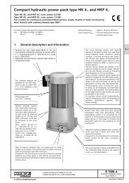
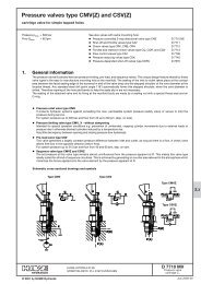
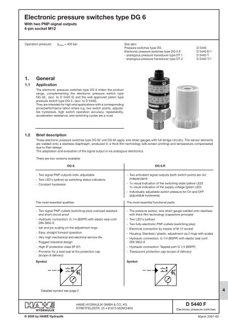
<strong>Electronic</strong> <strong>pressure</strong> <strong>switches</strong> <strong>type</strong> <strong>DG</strong> 6<br />
With two PNP-signal outputs<br />
4-pin socket M12<br />
Operation <strong>pressure</strong>: p max = 400 bar<br />
1. General<br />
1.1 Application<br />
The electronic <strong>pressure</strong> <strong>switches</strong> <strong>type</strong> <strong>DG</strong> 6 widen the product<br />
range, complementing the electronic <strong>pressure</strong> switch <strong>type</strong><br />
<strong>DG</strong> 5E.. (acc. to D 5440 E) and the well approved piston <strong>type</strong><br />
<strong>pressure</strong> switch <strong>type</strong> <strong>DG</strong> 3.. (acc. to D 5440).<br />
They are intended for high-end applications with a corresponding<br />
price/performance ration where e.g. two switch points, adjustable<br />
hysteresis, high switch operation accuracy, repeatability,<br />
acceleration resistance, and switching cycles are a must.<br />
1.2 Brief description<br />
These electronic <strong>pressure</strong> <strong>switches</strong> <strong>type</strong> <strong>DG</strong> 62 und <strong>DG</strong> 64 apply wire strain gauges with full bridge circuitry. The sensor elements<br />
are welded onto a stainless diaphragm, produced in a thick-film technology (silk-screen printing) and temperature compensated<br />
due to their design.<br />
The adaptation and evaluation of the signal output is via analogous electronics.<br />
There are two versions available:<br />
- Two signal PNP-outputs indiv. adjustable<br />
© 2005 by HAWE Hydraulik<br />
<strong>DG</strong> 6. <strong>DG</strong> 6.R<br />
- Two LED's (yellow) as switching status indicators<br />
- Constant hysteresis<br />
The most essential qualities:<br />
- Two signal PNP-outlets (switching plus) overload resistant<br />
and short-circuit proof<br />
- Hydraulic connection: G 1/4 (BSPP) with elastic seal conf.<br />
DIN 3852-E<br />
- bar and psi scaling on the adjustment rings<br />
- Easy, straight forward operation<br />
- Very high mechanical and electrical service life<br />
- Rugged industrial design<br />
- High IP protection class (IP 67)<br />
- Provision for a lead seal at the protection cap<br />
(scope of delivery)<br />
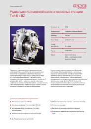
Symbol Symbol<br />
Detailed symbol see page 2<br />
HAWE HYDRAULIK GMBH & CO. KG<br />
STREITFELDSTR. 25 • 81673 MÜNCHEN<br />
See also:<br />
Pressure <strong>switches</strong> <strong>type</strong> <strong>DG</strong> D 5440<br />
<strong>Electronic</strong> <strong>pressure</strong> <strong>switches</strong> <strong>type</strong> <strong>DG</strong> 5 E D 5440 E/1<br />
- analogous <strong>pressure</strong> transducer <strong>type</strong> DT 1 D 5440 T<br />
- analogous <strong>pressure</strong> transducer <strong>type</strong> DT 2 D 5440 T/1<br />
- Two antivalent signal outputs (both switch points are not<br />
independent)<br />
- 1x visual indication of the switching state (yellow LED)<br />
1x visual indication of the supply voltage (green LED)<br />
- Individually adjustable switch <strong>pressure</strong> for On and OFF<br />
(adjustable hysteresis)<br />
The most essential functional parts:<br />
- The <strong>pressure</strong> sensor, wire strain gauge welded onto stainless<br />
with thick-film technology (capacitive principle)<br />
- Two LED's (yellow)<br />
- Two fully-electronic PNP-outlets (switching plus)<br />
- Electrical connection by means of M 12 socket<br />
- Housing: Stainless / plastic, adjustment via 2 rings with scales<br />
- Hydraulic connection: G 1/4 (BSPP) with elastic seal conf.<br />
DIN 3852-E<br />
- Hydraulic connection: Tapped port G 1/4 (BSPP)<br />
- Translucent protection cap (scope of delivery)<br />
D 5440 F<br />
<strong>Electronic</strong> <strong>pressure</strong> <strong>switches</strong><br />
March 2007-00<br />
4
D 5440 F page 2<br />
Circuitry Symbol<br />
<strong>DG</strong> 6<br />
<strong>DG</strong> 6.R<br />
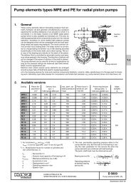
2. Available versions<br />
2.1 Type coding key, accessories<br />
2.1.1 Pressure switch<br />
Order coding: Type<br />
<strong>DG</strong> 62<br />
<strong>DG</strong> 64<br />
<strong>DG</strong> 61R<br />
<strong>DG</strong> 62R<br />
<strong>DG</strong> 64R<br />
Part No.<br />
6217 8124-00<br />
6217 8125-00<br />
6217 8133-00<br />
6217 8131-00<br />
6217 8132-00<br />
Pressure range<br />
0 ... 250 bar<br />
0 ... 400 bar<br />
0 ... 100 bar<br />
0 ... 250 bar<br />
0 ... 400 bar<br />
2.1.2 Assembly accessories<br />
Translucent protecting cap (scope of delivery) made of plastic (PA), provision for a lead seal<br />
Order coding MSD-T7 6217 8048<br />
M12-plug, 4-pin, angled:<br />
Order coding: X84G<br />
Straight male stud fitting with taper G 1/4<br />
(BSPP-internal) -G 1/4 (BSPP-external)<br />
for installation in arbitrary direction (turned<br />
around the longitudunal axis),<br />
acc.to D 7077<br />
Order coding: Y 9<br />
flange <strong>type</strong> adaptor<br />
(with hole pattern like for<br />
<strong>type</strong> <strong>DG</strong> 3.. acc. to D 5440)<br />
Note<br />
two independent signal<br />
outputs<br />
individually adjustable<br />
switch <strong>pressure</strong> for On<br />
and OFF
2.2 Technical data<br />
2.2.1 General data<br />
Nomenclature <strong>Electronic</strong> <strong>pressure</strong> switch<br />
Pressure connection G 1/4 A, male with cavety conf. DIN 3852 E with elastic seal<br />
Materials in contact V2A (1.4404), FKM<br />
with the <strong>pressure</strong> fluid<br />
Housing materials V4A (1.4404), PBT (Pocan), PC (Macrolon), FKM, protective cap PA (polyamide)<br />
Electrical connection Via plug M12, 4-pin (industrial standard).<br />
Available from HAWE as option, see sect. 2.1.2<br />
Installed position Any (dep. readability)<br />
Mass (weight) approx. 80 g<br />
Shock resistance 50 g, 11 ms acc. to DIN IEC 68-2-27<br />
Vibration resistance 20 g, 10-2000 Hz acc. to DIN IEC 68-2-6<br />
Protection class DIN<br />
EN 60529 or IEC 60529 IP 67 in properly installed state<br />
Protection class III. nach DIN EN 50178<br />
Ambient temperature -25° ... + 80°C<br />
Fluid temperature -25° ... + 80°C<br />
Electro-magnetic<br />
compatibility (EMC) Interference immunity acc. to EN 61000-4-2 ESD 4/8 kV<br />
EN 61000-4-3 HF radiated 10 V/m<br />
EN 61000-4-4 Burst 2 kV<br />
EN 61000-4-6 HF wire bound 10 V<br />
acc. to EC-directive 89/336/EWG<br />
with UL-CSA approval (UL-Listing Mark)<br />
D 5440 F page 3<br />
Attention: The device must be connected to a galvanically separated power supply and save guarded by a excessive current<br />
protection acc. to UL 248 to fulfill the limited voltage / current requirement acc. to UL 508!<br />
2.2.2 Hydraulic parameters<br />
<strong>DG</strong> 62 <strong>DG</strong> 64 <strong>DG</strong> 61R <strong>DG</strong> 62R <strong>DG</strong> 64R<br />
Measuring range [bar] 0 ... 250 0 ... 400 0 ... 100 0 ... 250 0 ... 400<br />
[PSI] 0 … 3625 0 .. 5800 0 ... 1450 0 ... 3625 0 ... 5800<br />
Perm. <strong>pressure</strong> overload p max [bar] 400 600 200 400 600<br />
[PSI] 5800 8700 2900 5800 8700<br />
Burst <strong>pressure</strong> p berst [bar] 1000 1600 1000 1000 1600<br />
[PSI] 14500 23200 14500 14500 23200<br />
Adjustment range:<br />
Set 1, Set 2 Set 1, Set 2 Set Set Set<br />
Switch point, SP [bar] 7.5 ... 250 12 ...400 5 ... 100 14 ... 250 20 ... 400<br />
[PSI] 109 ... 3625 174 ... 5800 72 ... 1450 203 ... 3625 290 ... 5800<br />
Hysterese Hysterese Reset Reset Reset<br />
Switching hysteresis/ [bar] 5.0 8,0 3 ... 98 8 ... 244 12 ... 392<br />
Set back point [PSI] 72 116 44 ... 1421 116 ... 3539 175 ... 5685<br />
Note:<br />
The evaluation system can be damaged in the range between p max and p burst but the device will not show external leakage.
D 5440 F page 4<br />
2.2.3 Electrical parameters<br />
Supply voltage U B<br />
Idle current consumption IL max. 25 mA (internal consumption)<br />
Max. perm. ripple factor 10% (ripple)<br />
Outputs (Short-circuit proof and overload resistant):<br />
Max. current IA max. 500 mA<br />
Voltage drop |UA max. 2 V DC<br />
Max. switching frequency 100 Hz<br />
Visual function displays:<br />
Switching states and/or 2 x yellow LED´s<br />
Supply voltage<br />
9,6 ... 32 V DC (protected against wrong polarity and overload up to 40 VDC)<br />
Precision:<br />
Switch point accuracy ±2,5% of the value of measuring range<br />
Repeatability ±0,5% of the value of measuring range<br />
Temperature drift ±0,5% of the value of measuring range / 10K<br />
in the compensated range 0 ... 80°C (TK)<br />
Switching cycles N > 50 million<br />
Switch point setting Via rings (may be locked)<br />
Insulation resistance 500 VDC > 100 MΩ<br />
Hysteresis 2% of the value of measuring range<br />
2.2.4 Electro-magnetic compatibility (EMC)<br />
The EMC of the device was checked by an accredited approval institute (Interference immunity acc. to EN 61000-4-X). This EMC<br />
test doesn't relieve the user from the proper execution of a specified EMC test for his complete system, since these test assemblies<br />
represent only a typical application (conforming the EC-guideline 89/336/EWG).<br />
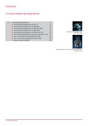
3. Unit dimensions<br />
All dimensions in mm, subject to change without notice!<br />
3.1 <strong>Electronic</strong> <strong>pressure</strong> switch<br />
Translucent protective cap is<br />
scope of delivery<br />
a/f 27<br />
max. torque 25 Nm<br />
Seal ring DIN 3869 14x1,5 FKM<br />
G 1/4 A
3.2 Assembly accessories<br />
MSD-T7 M12<br />
Plug<br />
X84G<br />
Straight male stud fitting G 1/4<br />
Terminals<br />
4. Assembly and adjustment manual<br />
4.1 Assembly<br />
Y 9<br />
Flange adapter<br />
D 5440 F page 5<br />
Mount the electronic <strong>pressure</strong> switch at a suitable test port (see assembly accessories, sect. 3.2).<br />
Max. torque 25 Nm<br />
Switch your system in unstressed mode and electrically connect the equipment via plug M12 (see assembly accessories in<br />
sect. 2.1.2). Please take into account, that no assembly accessory is scope of delivery with the <strong>pressure</strong> switch, therefore it must<br />
be ordered separately when required<br />
The protecting cap (scope of delivery) protects the adjustment rings against paint, dust etc. It also gives provision for a lead seal<br />
preventing unauthorized adjustment after the final setting procedure.<br />
Attention: Excessive <strong>pressure</strong> or <strong>pressure</strong> surges have to be prevented as they may harm the device.<br />
Pls. contact our service staff to prevent such effects.
D 5440 F page 6<br />
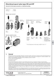
4.2 Adjustment<br />
Operating devices<br />
SET1 = Signal output NO-contact PIN 4<br />
SET2 = Signal output NO-contact PIN 2<br />
Procedure <strong>DG</strong> 6.<br />
a. Loosen the lock-ring (1)<br />
Both adjustment rings (2)<br />
may be set manually after loosening the lock-ring.<br />
<strong>DG</strong> 6. <strong>DG</strong> 6. R<br />
b. Adjust both adjustment rings (2) to the desired <strong>pressure</strong>.<br />
The scaling index (5) is printed onto the housing.<br />
c. Tighten the lock-ring (1)<br />
to fix the setting of both adjustment rings (2).<br />
d. LED-yellow (3) is ON, when SET1 is achieved.<br />
e. LED-yellow (6) is ON, when SET2 is achieved.<br />
f. The elastic seal ring (7) acc. to DIN 3869<br />
14x1.5 FKM may be replaced when necessary.<br />
g. Install the protective cap (a lead seal may be applied).<br />
SET = Signal output NO-contact PIN 4<br />
RESET = Signal output NC-contact PIN 2<br />
Procedure <strong>DG</strong> 6.R<br />
a. Loosen the lock-ring (1)<br />
Both adjustment rings (2)<br />
may be set manually after loosening the lock-ring.<br />
b. Adjust both adjustment rings (2) to the desired <strong>pressure</strong>.<br />
The scaling index (5) is printed onto the housing.<br />
c. Tighten the lock-ring (1)<br />
to fix the setting of both adjustment rings (2).<br />
d. LED-green (3) is ON, when supply voltage available<br />
e. LED-yellow (6) is ON, when SET is achieved<br />
and is OFF, when <strong>pressure</strong> falls below RESET-value.<br />
f. The elastic seal ring (7) acc. to DIN 3869<br />
14x1.5 FKM may be replaced when necessary.<br />
g. Install the protective cap (a lead seal may be applied).