T3 Manual - Studio Projects
T3 Manual - Studio Projects
T3 Manual - Studio Projects

You also want an ePaper? Increase the reach of your titles
YUMPU automatically turns print PDFs into web optimized ePapers that Google loves.
<strong>Studio</strong> <strong>Projects</strong> is manufactured and marketed under the direction of:<br />
PMI AUDIO GROUP<br />
USA: 1845 W. 169th Street, Gardena, California 90247<br />
voice: (310) 323-9050 facsimile: (310) 323-9051<br />
toll-free USA: (877) 563-6335<br />
UK: Unit 2 Babbacombe Business Park<br />
Babbacombe Road, Torquay, Devon TQ1 3SY<br />
tel: +44 (0) 1803 329848<br />
email: info@pmiaudio.com<br />
Pb<br />
visit our web site at studioprojects.com<br />
L e a d<br />
C e r t i f i e d<br />
F r e e P r o d u c t s<br />
C S E R I E S M I C R O P H O N E S<br />
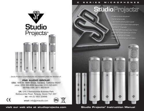
• Professional <strong>Studio</strong> Microphones<br />
• Transformerless circuitry<br />
• Large diameter pressure gradient capsule<br />
employing 6 um gold sputtered Mylar diaphragms<br />
• Low-noise FET Preamplifier<br />
• Dual Triode “6072” hand tested tubes (<strong>T3</strong> Only)<br />
• Multi-Pattern variable power supply (<strong>T3</strong> Only)<br />
• Heavy duty road case (All Models)<br />
• Elastic heavy duty shock mount (All Models)<br />
<strong>Studio</strong> <strong>Projects</strong> ® Instruction <strong>Manual</strong>
2 <strong>Studio</strong><strong>Projects</strong> www.studioprojects.com<br />
INSTRUCTION BOOK CONTENTS<br />
What is <strong>Studio</strong> <strong>Projects</strong>?...................................................................................................2<br />
Guidelines For Proper Care/Use ......................................................................................2<br />
Electrical Features…........................................................................................................3<br />
Operation………………………………………………….................................................4<br />
Troubleshooting Tips…………………………………………………..........………………5<br />
Origins and manufacture.................................................................................................6<br />
Applications....................................................................................................................6<br />
C1..................................................................................................................................7<br />
C3......................................................................................................................................8<br />
<strong>T3</strong>..................................................................................................................................9<br />
C4..................................................................................................................................10<br />
LSD2................................................................................................................................11<br />
WHAT IS STUDIO PROJECTS?<br />
Based in Gardena, California, <strong>Studio</strong> <strong>Projects</strong> is a line of microphones and electronics started in<br />
1999 by Alan Hyatt of PMI Audio Group. Our line of award winning microphones and preamps is<br />
a result of a partnership between PMI Audio and Beijing 797 Audio Co. LTD. a manufacturer of<br />
condenser microphones and professional audio products since 1952.<br />
Within the line, there is a broad and evolving range of tools designed to provide the engineer and<br />
recordist with a level of sonic quality and durability. <strong>Studio</strong> <strong>Projects</strong> continues to prove that innova-<br />
tive designs and years of experience produces quality products that fit well in all professional and<br />
home applications.<br />
If you have any questions or issues at any time, please feel free to contact us by phone or email,<br />
or log on to our web forum at http://www.pmiaudio.com/forums/.<br />
GUIDELINES FOR PROPER CARE/USE<br />
Large capsule capacitor mics such as the <strong>Studio</strong> <strong>Projects</strong> C-series, are built to handle a fairly<br />
substantial degree of abuse. However, one should always consider their investment and treat<br />
these mics with delicacy. The capsule itself is by far the most easily damaged component<br />
within the microphone. The biggest threat to a capsule is moisture and high humidity. A cap-<br />
sule corrupted by moisture, will lose sensitivity and exhibit a rumbling sound. This is due to the<br />
water molecules condensing within the very small gap between the diaphragm and backplate.<br />
When this occurs, the two plates cannot properly maintain their electrical charge. The result<br />
is that the microphone may become unusable and require repair. Since it is a lot more fun to<br />
make recordings than to send your mic to us for servicing, please consider the following:<br />
• Improper vocal recording technique is the primary cause of moisture-related capsule failure.<br />
Breathing on the transducer will cause the mylar diaphragm to immediately fog up. If this<br />
occurs repeatedly over time, the capsule will most likely short out.<br />
This may seem a bit ironic, since the microphones are intended for vocal use, but with proper<br />
care and technique, these problems can be avoided. One easy way to prevent moisture from<br />
reaching the capsule is to put some distance between the vocalist and the microphone. A<br />
distance of six to twelve inches is acceptable. It is common to see stage performers sing-<br />
ing directly into the grill of a handheld unit, but these are generally dynamic microphones,<br />
which are much more robust and employ an entirely different operating principle - which is<br />
not nearly so susceptible to moisture. Additionally, large diameter capacitor microphones are<br />
quite sensitive. It is not necessary to get right up on the grill. Doing so may in fact result in<br />
artifacts such as sibilance and popping. For reference, it may be of help to look up a picture<br />
of Frank Sinatra or Billie Holiday to observe how these legends placed themselves in relation<br />
to their microphones.<br />
• A pop filter is a device, used as an additional layer of protection between vocalist and<br />
microphone. Ideally suited for this purpose is the <strong>Studio</strong> <strong>Projects</strong> part# SP-MPF. Additional<br />
benefits of the use of a pop filter are the reduction of plosives and sibilance. <strong>Studio</strong> <strong>Projects</strong><br />
recommends the use of a pop filter for all vocal work where vocalist and microphone are in<br />
close proximity.<br />
• Provided with all <strong>Studio</strong> <strong>Projects</strong> microphones is a zipper pouch or hard shell case. When not<br />
in use, storing the microphones in these provided accessories will help to protect them from<br />
moisture, dust, scratches and dents.<br />
• A foam windscreen is included with each microphone for use in conditions where wind may<br />
interfere with sound pickup. To use, simply slide windscreen over microphone grill. Verify that<br />
microphone is properly oriented towards sound source, as it is harder to see which way the<br />
mic is facing once the windscreen is in place.<br />
• In the event of the microphone exhibiting loss of signal and or rumbling noise, place it in a<br />
warm, low humidity environment, such as the middle of the Sahara desert at high noon, or<br />
preferably several inches beneath an incandescent light bulb. This will help to remove any<br />
moisture. If problems persist, please contact <strong>Studio</strong> <strong>Projects</strong> directly using the contact infor-<br />
mation found in this manual.<br />
ELECTRICAL FEATURES<br />
The C1, C3, C4 & LSD2 require +48-volt phantom power to operate. Verify that your gain device<br />
(preamp, mixing console, etc.) provides this feature. Both microphones are solid state devices<br />
with externally polarized transducers, FET impedance conversion circuitry and active outputs.<br />
Their individual circuit topologies provide low noise and high sound pressure handling capabilities.<br />
The <strong>T3</strong> employs a separate power supply, which provides power to the microphone. The<br />
impedance circuitry is vacuum tube based with externally polarized transducer. The output<br />
is balanced, employing a humbucking transformer. The circuit topology provides very high<br />
sensitivity, low noise and high sound pressure handling capabilities.<br />
c_series_manual.indd 4-5 1/17/07 5:07:59 PM<br />
3
4 <strong>Studio</strong><strong>Projects</strong> www.studioprojects.com<br />
OPERATION<br />
C1 Using a male to female 3-pin XLR cable, plug microphone in to gain device (preamp,<br />
mixing console, etc.), making sure that +48-volt phantom power is active and gain is not at a<br />
level sufficient to cause ear-splitting feedback through monitor speakers. Address microphone<br />
from the side (not the top of the grill) above the SP logo badge. If bass cut is required, select<br />
one of two featured high pass filters. 150Hz setting will attenuate low frequencies by 6dB/<br />
octave starting at 150Hz. 75Hz. Setting will attenuate low frequencies by 6dB/octave at 75Hz.<br />
The “pad” switch reduces the signal level between the capsule and the circuitry. Engage<br />
-10dB or -20dB pad for very high sound pressure levels, which may otherwise overload micro-<br />
phone circuitry, causing distortion.<br />
C3 Using a male to female 3-pin XLR cable, plug microphone in to gain device (pre-<br />
amp, mixing console, etc.), making sure that +48-volt phantom power is active and gain<br />
is not at a level sufficient to cause ear-splitting feedback through monitor speakers.<br />
Address microphone from the side (not the top of the grill) above the SP logo badge.<br />
If bass cut is required, select 150Hz high pass filter. The “pad” setting reduces the sig-<br />
nal level between the capsule and the circuitry. Engage -10dB pad for very high sound<br />
pressure levels, which may otherwise overload microphone circuitry, causing distortion.<br />
Use the three-way switch on the front of the C3, below the SP logo, to adjust the direc-<br />
tional characteristics of the microphone between omnidirectional, cardioid and figure of eight:<br />
• Omnidirectional (O-shaped nomenclature): Sound from all directions is picked up by micro-<br />
phone without any side or rear attenuation.<br />
• Cardioid (Heart-shaped nomenclature): Some attenuation of sound occurs on sides and rear<br />
of microphone.<br />
• Figure of eight: Very significant attenuation of sound pickup on sides of microphone. Front<br />
and rear of microphone pick sound up equally, but 180° out of phase from one another.<br />
<strong>T3</strong> Plug power supply into ac receptacle. Connect 3-pin male to female XLR cable to output<br />
jack on front of power supply. Use included 7-pin XLR cable to connect microphone to power<br />
supply. Ensuring that gain device (mixing console, preamp, etc.) is not at a sufficient level to<br />
cause ear-splitting feedback. Turn on microphone power supply. Address microphone from the<br />
side (not the top of the grill) above the SP logo badge.<br />
*Note – Power supply has 110v/240v switch. Ensure that switch is set to proper AC voltage for<br />
your region. This switch is set at the factory at the time of manufacture according to region, but<br />
a microphone purchased used, for instance, may have the incorrect voltage setting.<br />
*Another note – The presence of or lack of +48- volt phantom power will not affect operation<br />
of <strong>T3</strong>.<br />
C4 Using a male to female 3-pin XLR cable, plug microphone in to gain device (preamp, mixing<br />
console, etc.) of course, all the while making sure that +48-volt phantom power is active and<br />
gain is not at a level sufficient to cause ear-splitting feedback through monitor speakers. Address<br />
microphone towards the grill mesh in the top of the microphone. Included with all C4 microphone<br />
pairs are two sets of capsules: two cardioid ( the ones with the holes around the circumference)<br />
and two omnidirectional (no holes around circumference). The threaded capsules may be<br />
changed by simply unscrewing one capsule and screwing another on to the amplifier body. Since<br />
the threads are delicate, take particular care not to “cross thread” the capsules during installation.<br />
It will not harm the microphone to change the capsule while still plugged in, but it will make<br />
a horrendous noise, so it is always best to perform this operation while the mic is unplugged, or<br />
the mic level is at minimum. If bass cut is required, select one of two featured high pass filters.<br />
150Hz setting will attenuate low frequencies by 6dB/octave starting at 150Hz. 75Hz. Setting will<br />
attenuate low frequencies by 6dB/octave at 75Hz. The “pad” switch reduces the signal level<br />
between the capsule and the circuitry. Engage -10dB or -20dB pad for very high sound pressure<br />
levels, which may otherwise overload microphone circuitry, causing distortion.<br />
LSD2 Using the included 7-pin to dual 3-pin XLR breakout cable, plug microphone into 2channel<br />
gain device (preamp, mixing console, etc.), making doubly sure that +48-volt phantom<br />
powers are active and gain is not at a level sufficient to cause ear-splitting feedback through<br />
monitor speakers. Address microphone from side (not the top of the grill). The switches used to<br />
control the upper capsule are located on the front of the microphone above the SP logo badge,<br />
while the control switches for the lower capsule are found on the rear of the mic. If bass cut is<br />
required, select 150Hz high pass filter. The “pad” setting reduces the signal level between the<br />
capsule and the circuitry. Engage -10dB pad for very high sound pressure levels, which may<br />
otherwise overload microphone circuitry, causing distortion. Adjust upper grill by grasping and<br />
turning. It’s that simple! Further application information regarding the LSD2 can be found at the<br />
<strong>Studio</strong> <strong>Projects</strong> website: www.studioprojects.com/downloads.html<br />
TROUBLESHOOTING TIPS<br />
No Sound Whatsoever:<br />
All C-series microphones require external voltage in order to operate. Verify that +48-volt phantom<br />
power (C1,C3,C4 & LSD2) is present. For <strong>T3</strong>, ensure that power supply is properly connected<br />
and power is on.<br />
Still No Sound (C1,C3,C4 & LSD2):<br />
Make sure microphone cable is XLR male to XLR female and connect only to inputs labeled “Mic<br />
In”, or “Microphone”, etc.<br />
The Back Of My C3/<strong>T3</strong> Sounds Different From The Front When Set To Figure Of Eight:<br />
Are you monitoring with headphones while talking into the mic? If so, the back of the mic will<br />
sound strange. This is because the rear diaphragm of the microphone takes the sound of your<br />
voice and flips it 180° out of phase. Meanwhile, the lower frequency range of your voice travels<br />
in phase along your jaw line to your ears. When the out of phase signal from the headphones<br />
meets the in-phase signal from your ears, the two signals are phase cancelled. Since this effect<br />
only occurs during the conditions described above, it will not affect recordings.<br />
c_series_manual.indd 6-7 1/17/07 5:08:00 PM<br />
5
6 <strong>Studio</strong><strong>Projects</strong> www.studioprojects.com 7<br />
TROUBLESHOOTING TIPS cont...<br />
Shockmount Looks As If It Should Fit On Mic Stand, But For Some Reason, It<br />
Will not Screw On:<br />
There are two standard thread sizes for mic stands, 5/8-27 and 3/8-16. <strong>Studio</strong> <strong>Projects</strong> shock-<br />
mounts ship with a brass reducer installed, which allows for the 3/8-16 threads. For use with 5/8-<br />
27 mic stand threads, unscrew adapter from shockmount, using a small coin as a screwdriver.<br />
Keep track of adapter when not in use – you never know when you may need it…<br />
ORIGINS AND MANUFACTURE<br />
<strong>Studio</strong> <strong>Projects</strong> Microphones are manufactured in Beijing, China by 797 Audio to a speci-<br />
fication defined by <strong>Studio</strong> <strong>Projects</strong>, Gardena, California. All <strong>Studio</strong> <strong>Projects</strong> microphones<br />
are inspected and tested at the factory, then inspected and tested again at PMI Audio<br />
Groups facility prior to shipping. <strong>Studio</strong> <strong>Projects</strong> microphones meet the require-<br />
ments of electronic equipment sold both in the USA, Canada, and the European Union.<br />
APPLICATIONS<br />
• Close miking of instruments with high sound pressure levels<br />
• Announcer’s mic for broadcasting/dubbing<br />
• Home recording and project studios<br />
• Vocalist recording<br />
• Spot mic for: wind instruments, strings, percussion and guitar amps.<br />
• XY - Coincident Cardioids<br />
• Mid-Side Method<br />
• Stereosonic Technique (Blumlein)<br />
• Overheads<br />
C1<br />
The <strong>Studio</strong> <strong>Projects</strong> C1 is an externally polarized cardioid pressure gradient<br />
transducer microphone with FET impedance converter. Diaphragm material<br />
is 6µm mylar for natural reproduction of vocals and instruments. It features<br />
dual selectable pads and high pass filters for a total of nine possible modes<br />
of operation. The output circuitry is active and is capable of driving long cable<br />
runs. The C1 is useful for all manner of recording work and music styles.<br />
C1 SPECIFICATIONS<br />
Type: Single diaphragm pressure<br />
gradient condenser microphone<br />
Polar pattern: Cardioid.<br />
Frequency response: 30Hz~20000Hz.<br />
Sensitivity: 14mV/Pa=-37dB (0dB=1V/Pa).<br />
Output impedance: 1000 Ohm.<br />
Max. SPL: 131 dB SPL for 1% THD @1000Hz<br />
(0dB SPL=0.00002Pa).<br />
Noise: (Line): 27 dB (A weighted) ---17 dB.<br />
S/N ratio: 77 dB.<br />
Power requirement: 48 +/- 4V.<br />
Current consumption:
8 <strong>Studio</strong><strong>Projects</strong> www.studioprojects.com 9<br />
C3<br />
The <strong>Studio</strong> <strong>Projects</strong> C3 is an externally polarized cardioid pressure gradient<br />
transducer microphone with FET impedance converter. Diaphragm material<br />
is 6µm mylar for natural reproduction of vocals and instruments. It features<br />
a selectable pad and high pass filters as well as three directional pattern<br />
settings: omnidirectional, cardioid and figure of eight. The output circuitry is<br />
active and is capable of driving long cable runs. The C3 is useful for all man-<br />
ner of recording work and music styles.<br />
C3 SPECIFICATIONS<br />
Type: 1 inch large dual diaphragm FET<br />
condenser microphone.<br />
Polar pattern: Cardioid/omni directional/figure of 8.<br />
Frequency response: 30Hz~20000Hz.<br />
Sensitivity: 12mV/Pa=-38dB (0dB=1V/Pa).<br />
Output impedance: 1000 Ohm.<br />
Max. SPL: 132/142/152dB SPL for<br />
1% THD @1000Hz<br />
Noise: (Line) ---28 dB (A weighted)---18 dB.<br />
S/N ratio: 76 dB.<br />
Power requirement: 48 +/- 4V.<br />
Current consumption:
10 <strong>Studio</strong><strong>Projects</strong> www.studioprojects.com 11<br />
C4<br />
The C4 is a 20mm diameter condenser microphone featuring interchangeable<br />
capsules, linear, low-noise, solid-state electronics, selectable<br />
-10dB/20dB pads and selectable 150Hz/75Hz high pass filters. It is<br />
intended for all-around use on stage, on location and in studios of all calibers.<br />
Used as an omnidirectional (pressure) microphone, the C4 offers a<br />
warm tonal response and is recommended for close miking in favorable<br />
acoustical environments. There is very little off axis coloration<br />
owing to the inherent nature of pressure capsules, and it is this<br />
- combined with the low self-noise of the mic circuitry that makes the<br />
C4 omni an excellent ambience mic –especially in pairs. In a good<br />
room, a pair of omnis can provide a vibrant and live feel to recordings,<br />
which is not achievable through the use of directional microphones.<br />
The C4 omni is intended for all manner of recording tasks, including vocal,<br />
piano and orchestral use.<br />
As a cardioid (pressure gradient) microphone, the C4 provides excellent<br />
pickup of on-axis sources while attenuating extraneous sound<br />
occurring from the side and rear of the mic. This makes it ideal for<br />
close miking of individual instruments where bleed from other nearby<br />
instruments or sound is undesirable. The C4 cardioids also make excellent stereo pairs for<br />
coincident and near-coincident miking techniques such as X-Y and ORTF. Additionally the<br />
C4’s are quite useful on a drum kit as overheads and on toms, not to mention snare drum.<br />
For increased side and some rear attenuation, the hypercardioid head (HC1) is available for<br />
the C4 microphone. This pressure gradient capsule is particularly useful for X-Y, ORTF, speech<br />
and dialog pickup, drum overheads and spot miking.<br />
The C4 microphone set is offered in pairs with mic stand clips (C4SC), foam windscreens (C4WS),<br />
stereo bar (SPSB) and hard shell carrying case.<br />
C4 SPECIFICATIONS<br />
Type: 20mm diameter condenser microphone with FET impedance converter.<br />
Polar pattern: Omni-directional pressure (OC1 head), pressure gradient cardioid<br />
(CC1 head), pressure gradient hypercardioid (optional HC1 head)<br />
Frequency response: 20Hz – 20kHz<br />
Sensitivity: -39dB/-39dB/-38dB<br />
Output impedance: 1200 Ohm.<br />
Max SPL: 158 dB SPL with -20dB pad<br />
Equivalent Noise: 18 dB SPL, (A-weighted per IEC268-15).<br />
S/N ratio: 76/76/77dB<br />
Power requirement: P48 +/- 4V<br />
Current consumption: 3.1ma<br />
Circuit: JFET follower, low distortion output buffer<br />
Connector: Gold-plated 3-pin XLR.<br />
Pad: -10dB/-20dB<br />
Low cut: 6 dB/Octave at 75Hz/150Hz<br />
Length: 4.90”(124.5mm)<br />
Diameter: .787” (20mm)<br />
Weight: 3.3oz. (92g)s<br />
LSD2<br />
The LSD-2 is a stereo microphone comprised of two separate dual-membrane solid<br />
state microphones contained within a single housing. Its capsules are mounted in<br />
close proximity on a vertical axis - the upper capsule assembly having the ability to<br />
rotate 270 degrees horizontally, relative to the lower capsule. Two C&K three-way<br />
switches control the polar response, high pass filtering and -10dB pad for each capsule<br />
(The switches on the front of the body correspond to the lower fixed capsule,<br />
while the switches 180° opposite on the back of the mic control the rotating upper<br />
capsule). It is the combination of capsule articulation and independent pattern<br />
switching which allows a user of the LSD2 to achieve all manner of coincident pair<br />
stereophonic recording techniques. Due to the close proximity of the capsules, there<br />
is no phase cancellation resulting from time delay between the two signals. This<br />
translates into excellent mono compatibility.<br />
The inner workings of the LSD-2 are essentially that of two <strong>Studio</strong> <strong>Projects</strong> Model<br />
C3 microphones. The capsules are 1.06” (27mm) diameter, dual membrane,<br />
Braunmuhl-Weber design. These are independently coupled through low-noise<br />
amplifiers based on FET driven discrete balanced output stages. The outer housing<br />
is plated brass with a single layer brass wire mesh grill surrounding the capsules.<br />
Included with the LSD-2 microphone is a dedicated 7-pin XLR to dual 3-pin XLR “Y”<br />
cable, magnum-sized foam windscreen, standard shockmount and carrying case.<br />
LSD2 SPECIFICATIONS<br />
Type: Stereo condenser microphone with vertically<br />
coincident 1.06” (27mm.) dual diaphragms.<br />
Polar pattern: Cardioid, Omni directional Figure of 8<br />
Frequency response: 30~20000Hz.<br />
Sensitivity: 12mV/Pa=-38dB(0dB=1V/Pa).<br />
Output impedance: 1200 Ohm.<br />
Max. SPL: 132/142dB SPL for 1% THD @1000Hz(0dB/-10dB pad,<br />
0dB SPL=0.00002Pa).<br />
Noise: (Line)---28 dB (A weighted)---18 dB-A.<br />
S/N ratio: 76 dB.<br />
Circuit: JFET impedance converter, discrete balanced output<br />
Power requirement: 24v.-52.5v. phantom power x 2<br />
Current Consumption: 2.5mA<br />
Connector: Gold-plated 7-pin XLR breakout cable<br />
Size: 2.1” (53.34mm.) dia.<br />
Weight: 1.8 lbs.<br />
c_series_manual.indd 12-13 1/17/07 5:08:04 PM
STATEMENT OF ROHS COMPLIANCE<br />
PMI Audio Group manufactures complete electronic products which are covered<br />
by the European Union’s “Removal of Hazardous Substances” directive<br />
2002/95/EC (RoHS). This directive seeks to eliminate toxic substances from<br />
the manufacturing process, such that when equipment is disposed of at the<br />
end of its life cycle, the materials it contains do not contaminate the environment<br />
and pose health risks. Banned substances are lead, mercury, cadmium,<br />
hexavalent chromium, polybrominated biphenyls (PBB) and polybrominated<br />
diphenyl ethers (PBDE). Lead is used together with tin in solder connections to<br />
reduce the melting point of solder. Lead-free solder requires higher soldering<br />
temperatures which in turn places greater thermal stress on components.<br />
PMI Audio Group takes seriously its obligations under the RoHS directive and insists that its<br />
factories use only components that are certified RoHS compliant, as well as leadfree solder. In a<br />
very few cases the necessary components may not yet be available to the world market but we<br />
work continuously to eliminate any such exceptions at the earliest opportunity. Our printed Circuit<br />
Boards (PCB’s) and all soldered joints have been lead-free since 2005.<br />
STATEMENT OF WEEE POLICY<br />
PMI Audio Group manufactures many complete electronic products which are covered<br />
by the European Union’s “Waste Electric and Electronic Equipment” directive 2002/96/EC<br />
(WEEE). This directive seeks to ensure that waste electric and electronic equipment is<br />
disposed of in an environmentally responsible manner, at the end of its life cycle. PMI<br />
Audio Group takes seriously its obligations under this directive to take back WEEE-affected<br />
products and, from 13th August 2005, will mark all such products with the crossed-out<br />
wheeled bin symbol.<br />
Business to Business products: PMI Audio Group will cost-neutrally take back WEEE-affected electric and<br />
electronic equipment in this category, from 1st January 2006. PMI Audio Group will work with disposal and<br />
recycling partners working within the EU. The waste electric and electronic equipment can then be turned over<br />
to a disposal and recycling companies in the countries concerned.<br />
Business to Customer products: emerging electric and electronic equipment will be disposed of by local authorities’<br />
collection systems.<br />
Dual Use products: this equipment will be disposed of by local authorities’ collection systems.<br />
IMPORTANT SAFETY INFORMATION<br />
CAUTION: TO REDUCE THE RISK OF ELECTRIC SHOCK, DO NOT REMOVE<br />
COVER. NO USER-SERVICEABLE PARTS INSIDE. REFER SERVICING TO QUALI-<br />
FIED SERVICE PERSONNEL.<br />
The lightning flash with arrowhead symbol, within equilateral triangle, is intended to alert the user to the<br />
presence of uninsulated “dangerous voltage” within the product’s enclosure that may be of sufficient<br />
magnitude to constitute a risk of electric shock to persons.<br />
The exclamation point within an equilateral triangle is intended to alert the user to the presence<br />
of important operating and maintenance (servicing) instructions in the literature accompanying the appliance.<br />
WARNING: TO AVOID FIRE OR ELECTRIC<br />
SHOCK HAZARD, DO NOT EXPOSE THIS<br />
APPARATUS TO WATER, RAIN OR MOISTURE.<br />
This appliance has a serial number located on the rear panel. Please record the model number and serial<br />
number and retain them for your records.<br />
Model number<br />
Serial number<br />
NOTE — This apparatus does not exceed the Class A/Class B (whichever is applicable) limits for radio noise<br />
emissions from digital apparatus as set out in the radio interference regulations of the Canadian Department of<br />
Communications.<br />
ATTENTION — Le présent appareil numérique n’émet pas de bruits radioélectriques dépassant las limites<br />
applicables aux appareils numériques de class A/de class B (selon le cas) prescrites dans le réglement sur le brouillage<br />
radioélectrique édicté par les ministere des communications du Canada.<br />
These limits are designed to provide reasonable protection against harmful interference in a commercial/residential<br />
installation respectively. This equipment generates, uses, and can radiate radio frequency energy and, if not<br />
installed and used in accordance with the instruction manual, may cause harmful interference to radio communications.<br />
There is no guarantee that interference will not occur in a particular installation. If this equipment does<br />
cause interference to radio or television equipment reception, which can be determined by turning the equipment<br />
off and on, the user is encouraged to try to correct the interference by any combination of the following measures:<br />
(1) Relocate or reorient the receiving antenna (2) Increase the separation between the equipment and the receiver<br />
(3) Plug the equipment into an outlet on a circuit different from that to which the receiver is connected (4)<br />
Consult your dealer or experienced radio/television technician for additional assistance.<br />
CAUTION — Changes or modifications to this equipment not expressly approved by the party responsible for<br />
compliance could void the user’s authority to operate this equipment.<br />
IMPORTANT SAFETY INSTRUCTIONS<br />
1. Read these instructions.<br />
2. Keep these instructions.<br />
3. Heed all warnings.<br />
4. Follow all instructions.<br />
5. Do not use this apparatus near water. Do not expose to drips or splashes. Do not place any objects filled with<br />
liquids, such as vases, on the apparatus.<br />
6. Clean only with dry cloth.<br />
7. Do not block any ventilation openings. Do not install this apparatus in a confined space such as a book case<br />
or similar unit. Install only in racks designed for the purpose and in accordance with manufacturers’ instructions.<br />
8. Do not install near any heat sources such as radiators, heat registers, stoves, or other apparatus (including<br />
amplifiers) that produce heat.<br />
9. Do not defeat the safety purpose of the polarized or grounding-type plug. A polarized plug has two blades<br />
with one wider than the other. A grounding-type plug has two blades and a third grounding prong. The wide<br />
blade or the third prong are provided for your safety. If the provided plug does not fit into your outlet, consult an<br />
electrician for replacement of the obsolete outlet.<br />
10. Protect the power cord from being walked on or pinched particularly at plugs, convenience receptacles, and<br />
the point where they exit from the apparatus.<br />
11. Only use attachments/accessories specified by the manufacturer.<br />
12. Use only with a cart, stand, tripod, bracket, or table specified by the manufacturer, or sold<br />
with the apparatus. When a cart is used, use caution when moving the cart/apparatus combination<br />
to avoid injury from tip-over.<br />
13. Unplug this apparatus during lightning storms or when unused for long periods of time.<br />
14. Refer all servicing to qualified service personnel. Servicing is required when the apparatus<br />
has been damaged in any way, such as power-supply cord or plug is damaged, liquid has been<br />
spilled or objects have fallen into the apparatus, the apparatus has been exposed to rain or<br />
moisture, does not operate normally, or has been dropped.<br />
15. Apparatus designed with Class-I construction must be connected to a mains socket outlet with a protective<br />
earthing connection (the third grounding prong).<br />
16. This apparatus may be equipped with a single-pole, rockerstyle AC mains power switch. If so this switch is<br />
located on the front panel and should remain readily accessible to the user.<br />
17. The manufacturer reserves the right to change the technical specification of the product without prior<br />
notice.<br />
c_series_manual.indd 14-15 1/17/07 5:08:06 PM
NOTES<br />
c_series_manual.indd 16-17 1/17/07 5:08:06 PM<br />
NOTES
STUDIO PROJECTS LIMITED WARRANTY<br />
T H I S P R O D U C T I S F O R P R O F E S S I O N A L U S E O N L Y<br />
PMI Audio Group warrants that all products will be free from defects in material or workmanship:<br />
A: For a period of (3) years from the date of purchase (hereinafter the labor warranty period), PMI<br />
Audio Group will repair or replace this Product if determined to be defective. After the expiration<br />
of the labor warranty period, the Purchaser must pay labor charges.<br />
B: In addition, PMI Audio Group will supply, at no charge, replacements for defective parts for<br />
a period of (3 years) from the date of purchase. During the labor warranty period, to repair the<br />
Product, Purchaser must return the defective Product, freight prepaid, or deliver it to PMI Audio<br />
Group Service Center. The product to be repaired is to be returned in either its original carton or<br />
a similar package affording an equal degree of production. PMI Audio Group will return the repaired<br />
Product freight prepaid to the Purchaser. PMI Audio Group is not obligated to provide Purchaser<br />
with a substitute unit during the warranty period or at any time. PMI Audio does not Warranty consumables<br />
like tubes that wear from normal use.<br />
CONDITIONS<br />
1. Notification of claims: Warranty Service: If Purchaser discovers that the Product has proven<br />
defective in material or workmanship, then written notice with an explanation of the claim shall<br />
be given promptly by Purchaser to PMI but all claims for warranty service must be made within<br />
the warranty period. If after investigation PMI determines that the reported problem was not<br />
covered by the warranty, Purchaser shall pay PMI for the cost of investigating the problem at its<br />
then prevailing time-and-materials rate. No repair or replacement by Purchaser of any Product<br />
or part thereof shall extend the warranty period as to the entire Product. The specific warranty<br />
on the repaired part only shall be in effect for a period of ninety (90) days following the repair or<br />
replacement of that part or the remaining period of the Product warranty, whichever is greater.<br />
2. Exclusive Remedy: Acceptance: Purchaser’s exclusive remedy and PMI’s sole obligation is<br />
to supply (or pay for) all labor necessary to repair any product found to be defective within the<br />
warranty period and to supply, at no extra charge, new or rebuilt replacements for defective<br />
parts. If repair or replacement fails to remedy the defect, then and only in such an event, shall<br />
PMI exchange to Purchaser a new or reconditioned unit. Purchaser’s failure to make a claim as<br />
provided in paragraph 1 above or continued use of the product shall constitute an unqualified<br />
acceptance of such Product and a waiver by Purchaser of all claims thereto.<br />
3. Exceptions to Limited warranty: PMI shall have no liability or obligation to Purchaser with<br />
respect to any Product subjected to abuse, improper use, negligence, accident, modification,<br />
failure of the end-user to follow the operating and maintenance procedures outlined in the users<br />
manual, attempted repair by non-qualified personnel, operation of the unit outside of the published<br />
environmental and electrical parameters, or if such products original identification (trademark,<br />
serial number) markings have been defaced, altered, or removed. PMI excludes from<br />
warranty coverage, Products sold AS IS and/or WITH ALL FAULTS and excludes used products<br />
which have not been sold by PMI to the Purchaser. PMI also excludes from warranty coverage<br />
consumables such as fuses and batteries, etc.<br />
4. Proof of purchase: The dealer’s dated bill of sale must be retained as evidence or the date of<br />
purchase and to establish warranty eligibility.<br />
DISCLAIMER OF WARRANTY<br />
EXCEPT FOR THE FORGOING WARRANTIES, PMI HEREBY DISCLAIM S AND EXCLUDES<br />
ALL OTHER WARRANTIES, EXPRESS OR LIMITED, INCLUDING, BUT NOT LIMITED TO ANY/OR ALL IMPLIED<br />
WARRANTIES OF MERCHANT ABILITY, FITNESS FOR A PARTICULAR PURPOSE AND/OR ANY WARRANTY WITH<br />
REGARD TO ANY CLAIM OF INFRINGEMENT THAT MAY BE PROVED<br />
IN SECTION 2-312(3) OF THE UNIFORM COMMERCIAL CODE AND/OR IN ANY COMPARABLE STATE STATUE. PMI<br />
HEREBY DISCLAIMS ANY REPRESENTATIONS OR WARRANTY THAT THE PRODUCT IS<br />
COMPATIBLE WITH ANY COMBINATION OF NON-PMI AUDIO PRODUCTS PURCHASER MAY<br />
CHOOSE TO CONNECT TO THE PRODUCT.<br />
LIMITATION ON LIABILITY<br />
THE LIABILITY OF PMI, IF ANY, AND PURCHASER’S SOLE AND EXCLUSIVE REMEDY FOR<br />
DAMAGES FOR ANY CLAIM OF ANY KIND WHATSOEVER, REGARDLESS OF THE LEGAL THEORY<br />
AND WHETHER ARISING IN TORT OR CONTRACT, SHALL NOT BE GREATER THAN THE ACTUAL<br />
PURCHASE PRICE OF THE PRODUCT WITH RESPECT TO WHICH SUCH CLAIM IS MADE. IN NO<br />
EVENT SHALL PMI BE LIABLE TO PURCHASER FOR ANY SPECIAL, INDIRECT, INCIDENTAL, OR<br />
CONSEQUENTIAL DAMAGES OF ANY KIND INCLUDING, BUT NOT LIMITED TO, COMPENSATION,<br />
REIMBURSEMENT OR DAMAGES ON ACCOUNT OF THE LOSS OF PRESENT OR<br />
PROSPECTIVE PROFITS OR ANY OTHER REASON WHATSOEVER.<br />
Information in this User Guide is subject to change without notice. No part of this User Guide may be reproduced or transmitted in any form or<br />
by any means, electronic, mechanical or by any other means, for any purpose, without the express written permission of PMI Audio Group.<br />
PMI Audio Group may have trademarks, copyrights or other intellectual property rights covering the subject matter of this User Guide. Except<br />
as expressly provided in any written agreement from PMI Audio Group, the furnishing of this User Guide is provided for the sole use of the<br />
authorized User [or Service Agent where applicable] and does not give the User any license to use any trademarks, copyrights or other intellectual<br />
property of PMI Audio Group.<br />
PMI, PMI AUDIO, TED FLETCHER, MEEQUALIZER, STUDIO PROJECTS, JOEMEEK, TOFT AUDIO DESIGNS, CURRENTSENSE,<br />
MEEKROPHONE, TRAKPAK, and (If it Sounds Right...It is Right!) are either registered trademarks or trademarks of PMI Audio Group in the<br />
U.S.A. and/or other countries.<br />
Copyright © 2006 PMI Audio Group. All rights reserved.<br />
OWNERS REGISTRATION CARD<br />
T O B E C O M P L E T E D A T T I M E O F P U R C H A S E<br />
Name ____________________________________________________<br />
Date of Purchase ____________________________________________________<br />
Serial Number ____________________________________________________<br />
Dealer’s Name ____________________________________________________<br />
R E TA I N F O R Y O U R R E C O R D S<br />
P L E A S E D I S PAT C H A N D R E T U R N Y O U R R E G I S T R AT I O N T O<br />
S T U D I O P R O J E C T S W I T H I N 1 4 D AY S O F P U R C H A S E<br />
c_series_manual.indd 18-19 1/17/07 5:08:07 PM
❏ MIX ❏ Electronic Musician ❏ EQ ❏ Home Recording ❏ Pro Audio Review ❏ Recording ❏<br />
Pro Sound News<br />
What magazines do you read to influence your buying decision: (please check all that apply)<br />
Comments:<br />
Serial Number: Dealer:<br />
Model Purchased: Date Purchased:<br />
Telephone Number: email Address:<br />
City: State: Zip Code:<br />
Address:<br />
Name:<br />
PRODUCT REGISTRATION INFORMATION<br />
PLEASE FILL IN THE BELOW SECTIONS AND RETURN<br />
Place<br />
Stamp<br />
Here<br />
c_series_manual.indd 20-21 1/17/07 5:08:07 PM<br />
STUDIO PROJECTS<br />
D I S T R I B U T E D B Y P M I A U D I O G R O U P<br />
1845 W. 169th Street<br />
Gardena, CA 90247 USA