Evaluation board Die & AD7745 - microFAB Bremen GmbH
Evaluation board Die & AD7745 - microFAB Bremen GmbH
Evaluation board Die & AD7745 - microFAB Bremen GmbH

Create successful ePaper yourself
Turn your PDF publications into a flip-book with our unique Google optimized e-Paper software.
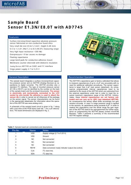
Sample Board<br />
Sensor E1.3N/E8.0T with <strong>AD7745</strong><br />
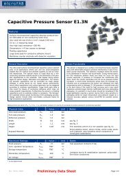
Features<br />
Surface micromachined capacitive absolute pressure<br />
sensor fabricated on non-conductive fused silica<br />
Very small die size (0.6x1.2 mm², height 0.48 mm)<br />
0.5 to 1.3 (E1.3N)/1.2 to 8.0 (E8.0T) measuring range<br />
Very high input resistance >300 MΩ<br />
Overpressure >9 bar causes no damage<br />
Floating capacitance<br />
Large bond pads for conductive adhesive mount<br />
Membrane counter electrode with dielectric insulation<br />
Analog Devices <strong>AD7745</strong> as CADC and I²C interface<br />
Singe power supply 2.7 to 5.25 V<br />
General Description Recommended Operation<br />
The sample <strong>board</strong> integrates a surface micromachined capacitive<br />
pressure sensor and an <strong>AD7745</strong> (Analog Devices) as capacitance<br />
to digital converter. The <strong>AD7745</strong> provides also a<br />
standard I 2 C interface. The type of mounted pressure sensor<br />
(E1.3N or E8.0T) can be identified by the number on the back<br />
of the sample <strong>board</strong> and the enclosed documents. The sensor<br />
is electrically and mechanically connected to the LCC<br />
socket by wire bonds! No adhesive is used to attach the<br />
sensor die in order to cancel out all influences of the package<br />
on the sensor signal. The sensor characteristics can be found<br />
in the appropriate datasheets (for information about the operation<br />
of the <strong>AD7745</strong> see www.analog.com).<br />
A schematic of the sample <strong>board</strong> circuit is given in fig. 1 along<br />
with a top-view of the PCB layout (see tab. 1 for a pin description).<br />
The <strong>board</strong> dimensions are displayed in fig. 2.<br />
Table 1: Sample <strong>board</strong> pin connections and descriptions.<br />
Pin-No. Name Notes<br />
1 VDD Supply voltage (2.7 to 5.25 V)<br />
2 VSS Ground<br />
3 NC Not connected<br />
4 NC Not connected<br />
5 NC Not connected<br />
6 RDY# Data conversion ready indicator output (low active).<br />
7 CLK I 2 C clock line.<br />
8 SDA I 2 C data line.<br />
The <strong>AD7745</strong>’s capacitance gain is factory calibrated that allows<br />
to measure capacitances of up to ±4 pF very accurately with no<br />
need for additional calibration procedures. The sensor capacitance<br />
is larger than 4 pF (see sensor datasheet). As consequence<br />
programmable internal capacitances need to be<br />
switched to the inputs of the <strong>AD7745</strong> which are subtracted from<br />
the external capacitance under test in order to meet the required<br />
maximum capacitance range of the <strong>AD7745</strong>. Unfortunately,<br />
these internal capacitances are not factory calibrated<br />
and can vary up to ±20% (see datasheet <strong>AD7745</strong>).<br />
As consequence the sensor offset shifts accordingly but gain<br />
remains accurate. In case if a large pressure range is applied<br />
to the sensors, its capacitance swing exceeds 8 pF. In order to<br />
readout the capacitance over the whole range the gain registers<br />
of the <strong>AD7745</strong> need to be reprogrammed (for further assistance<br />
on programming the <strong>AD7745</strong> please contact <strong>microFAB</strong><br />
<strong>Bremen</strong>). Table 2 presents a summary of the recommended<br />
<strong>AD7745</strong> register settings.<br />
Rev. 09.01.2008 Preliminary Page 1/2
Table 2: Recommended register settings for the operation of the <strong>AD7745</strong>.<br />
Register Adress Value Notes<br />
Cap Setup 0x07 0x80, 0b1000 0000<br />
VT Setup 0x08 0x81, 0b1000 0001<br />
EXC Setup 0x09 0x0B, 0b0000 1011<br />
Configuration 0x0A 0xFA, 0b1111 1010<br />
CAP DAC A 0x0B<br />
(E1.3N) 0xC0, 0b1100 0000<br />
(E8.0T) 0xC9, 0b1100 1001<br />
CAP DAC B 0x0C 0x80, 0b1000 0000<br />
Enables single conversion on the capacitive channel and disables the<br />
differential capacitance mode.<br />
Enables single conversion on the temperature channel, sets the internal<br />
temperature sensor active and switches internal chopping on.<br />
Enables EXCA as excitation output with an excitation voltage level of<br />
VDD/2.<br />
Slowest and most accurate capacitance and temperature conversion is<br />
selected (update rate: 8.2 Hz (temperature) 9.1 Hz (capacitance)) together<br />
with single conversion mode. Writing into the configuration register triggers<br />
the sensor evaluation.<br />
An offset capacitance of 10.6 pF/12.1 pF (E1.3N/E8.0T, ±20%) is subtracted<br />
from the positive capacitive input by writing 0x40/0x49 into the lower<br />
bits (bits 0 to 6) of CAP DAC A register. This offset allows to readout the<br />
E1.3N in a pressure range of 0.2 up to 7 bar and the E8.0T in a range of<br />
1.1 to 5 bar. This register value needs to be altered to shift the readout<br />
range. The CAP DAC A must be enabled by writing a logic 1 into bit 7 of the<br />
CAP DAC A register.<br />
By setting bits 0 through 6 to zero no capacitance offset is switched to the<br />
negative capacitive input. CAP DAC B must be enabled by writing a logic 1<br />
into bit 7.<br />
Fig. 1: Sample <strong>board</strong> schematic (left) and top-view of PCB-layout (right).<br />
Fig. 2: Dimensional drawing of PC sample <strong>board</strong> (top-view).<br />
<strong>microFAB</strong> <strong>Bremen</strong> <strong>GmbH</strong><br />
Lise-Meitner-Strasse 5<br />
28359 <strong>Bremen</strong><br />
Germany<br />
fon +49 (0)421 24100-0<br />
fax +49 (0)421 24100-99<br />
Rev. 09.01.2008 Preliminary www.microfab.de<br />
Page 2/2