The KJ5VW 20 Meter Mini Yagi - Nonstop Systems
The KJ5VW 20 Meter Mini Yagi - Nonstop Systems
The KJ5VW 20 Meter Mini Yagi - Nonstop Systems

Create successful ePaper yourself
Turn your PDF publications into a flip-book with our unique Google optimized e-Paper software.
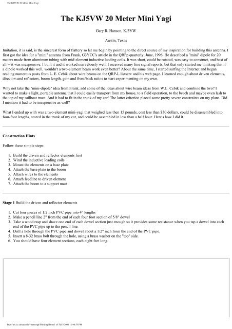
<strong>The</strong> <strong>KJ5VW</strong> <strong>20</strong> <strong>Meter</strong> <strong>Mini</strong> <strong>Yagi</strong><br />
<strong>The</strong> <strong>KJ5VW</strong> <strong>20</strong> <strong>Meter</strong> <strong>Mini</strong> <strong>Yagi</strong><br />
Gary R. Hanson, <strong>KJ5VW</strong><br />
Austin, Texas<br />
Imitation, it is said, is the sincerest form of flattery so let me begin by pointing to the direct source of my inspiration for building this antenna. I<br />
first got the idea for a "mini" antenna from Frank, G3YCC's article in the QRPp quarterly, June, 1996. He described a "mini" dipole for <strong>20</strong><br />
meters made from aluminum tubing with mid-element inductive loading coils. It was short, could be rotated, was easy to construct, and best of<br />
all -- it was inexpensive. I built it and it worked marvelously well. I received many fine signal reports, but that only started me thinking that if<br />
a dipole worked this well, wouldn't a two-element beam work even better? About the same time, I started surfing the Internet and began<br />
reading numerous posts from L. E. Cebik about wire beams on the QRP-L listserv and his web page. I learned enough about driven elements,<br />
directors and reflectors, boom length, gain and front/back ratios to start experimenting on my own.<br />
Why not take the "mini-dipole" idea from Frank, add some of the ideas about wire beam ideas from W.L. Cebik and combine the two? I<br />
wanted to make a light, portable antenna that I could easily transport from my house, to a field operation, to the beach and maybe even lash to<br />
the top of my sailboat mast. And it had to fit in the trunk of my car! <strong>The</strong> latter criterion placed some pretty severe constraints on my plans. Did<br />
I mention it had to be inexpensive as well?<br />
What I ended up with was a two-element mini-yagi that weighed less then 15 pounds, cost less than $30 dollars, could be disassembled into<br />
four-foot lengths, stored in the trunk of my car, and could be assembled in less than a half hour. Here's how I did it.<br />
Construction Hints<br />
Follow these simple steps:<br />
1. Build the driven and reflector elements first<br />
2. Wind the inductive loading coils<br />
3. Mount the elements on a base plate<br />
4. Attach the base plate to the boom<br />
5. Attach wires to the elements<br />
6. Attach feedline to driven element<br />
7. Attach the boom to a support mast<br />
Stage 1 Build the driven and reflector elements<br />
1. Cut four pieces of 1/2 inch PVC pipe into 4" lengths<br />
2. Make a pencil line 2" from the end of each four foot section of 5/8" dowel<br />
3. Take a wood rasp and shave one end of each dowel section just enough so it provides some resistance when you tap a dowel into each<br />
end of the PVC pipe up to the pencil line.<br />
4. Drill a hole through the PVC pipe and dowel about a 1/2" inch from the end of the PVC pipe.<br />
5. Insert a 8-32 brass bolt through the hole, using a brass washer on the "top" side.<br />
6. You should have four element sections, each eight feet long.<br />
http://uts.cc.utexas.edu/~hansongr/<strong>Mini</strong>yagi.htm (1 of 5)2/5/<strong>20</strong>06 12:40:55 PM
<strong>The</strong> <strong>KJ5VW</strong> <strong>20</strong> <strong>Meter</strong> <strong>Mini</strong> <strong>Yagi</strong><br />
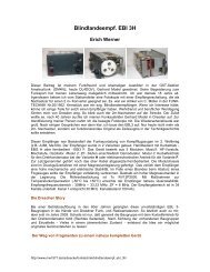
Stage 2 Wind the inductive coils<br />
1. Cut a 7' 6" length of #22 plastic covered hook-up wire for each of the four coils.<br />
2. Attach one end of the wire under the brass bolt and washer on the "left" side of the coil.<br />
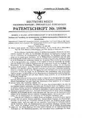
3. Wind the coil over the top of the PVC form in a clockwise fashion for 32 turns and then attach the free end under the brass bolt and<br />
washer on the "right" side of the coil.<br />
4. I used electrical spade connectors crimped on the end of the wires to slip under the bolt head and washer.<br />
5. Make four of these coils and wrap them with electrical tape to hold the windings in place.<br />
Here's what the inductive coils should like when you have finished.<br />
http://uts.cc.utexas.edu/~hansongr/<strong>Mini</strong>yagi.htm (2 of 5)2/5/<strong>20</strong>06 12:40:55 PM
<strong>The</strong> <strong>KJ5VW</strong> <strong>20</strong> <strong>Meter</strong> <strong>Mini</strong> <strong>Yagi</strong><br />
Stage 3 Attach the beam elements to a base plate<br />
1. Cut two 1" x 2" pieces of oak to a length of 2 feet.<br />
2. Mark a "center" line at the 12" inch mark and space the holes for your corner "L" brackets on the back side of the base plate so the boom<br />
will attach<br />
3. Drill the holes for mounting your "L" brackets, but do not attach them.<br />
4. Place one end of a element up to the center line and drill a mounting hole through the wood dowel so it either lines up with an existing<br />
hole for the "L" bracket or so that you create a new hole through the base plate and "L" corner bracket.<br />
5. Drill a second hole through the dowel and base plate about an inch from the end of the base plate.<br />
6. Attach two wood elements and the two "L" brackets to each base plate and secure with 8-32 brass nuts and bolts<br />
Stage 4 Attach the base plates and elements to the boom<br />
1. Cut a 1" x 2" piece of oak to a length of 8' 3-1/2"<br />
2. Mark the mounting holes for the "L" brackets on the boom.<br />
3. Drill the holes and attach the boom to each base plate using 8-32 brass nuts and bolts<br />
4. Measure the center point of the boom length with a pencil line and drill holes for inserting a U-bolt clamp for mounting the boom to the<br />
mast.<br />
Stage 5 Attach the wires to the elements<br />
Driven Element<br />
1. Measure two lengths of wire to run from the center of the element to the inductive coil, but allow about a 1" to an 1-1/2" gap at the<br />
center for attaching your transmission line (either a coaxial connector or ladder line). This length is not that critical as long as they are<br />
the same length on each side.<br />
2. Attach electrical spade connectors to one end of the wire and place this end under one of the brass bolts and washer. Attach the other<br />
end to your feedline connector. I soldered mine directly to a PL259 socket mounted on a piece of plastic cut from a peanut butter jar<br />
cover. Do the same for the opposite side of the driven element.<br />
3. Cut a second set of wires that run from the "outside" of the inductive coil out past the end of the wood dowel by about two inches.<br />
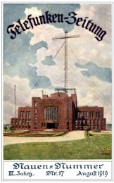
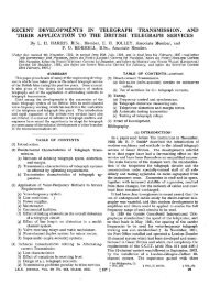
After you mount your yagi at a given height you will come back and cut this "outer" wire on the driven element to resonate your antenna to the<br />
appropriate frequency. This driven element cut to these lengths should resonate below 14.000 Mhz and you can cut it a little shorter to bring it<br />
up to whatever frequency you desire. I got mine to resonate right about 14.070 Mhz. See the SWR chart below.<br />
Reflector element<br />
1. Follow the steps for the driven element but resonate the total length to a frequency about 5% below the driven element. That is, you<br />
want this reflector element to be longer. I ended up with my "outside" wire about 6 inches past the end of the wood dowel.<br />
2. After you find the resonant point, replace the two center wires with one wire that runs from one inductive coil to the other with no break<br />
in it.<br />
Stage 6 Attach the transmission line to the driven element<br />
http://uts.cc.utexas.edu/~hansongr/<strong>Mini</strong>yagi.htm (3 of 5)2/5/<strong>20</strong>06 12:40:55 PM
<strong>The</strong> <strong>KJ5VW</strong> <strong>20</strong> <strong>Meter</strong> <strong>Mini</strong> <strong>Yagi</strong><br />
1. Since I was using RG-58U coaxial cable and I wanted to using this antenna without a tuner out in the field, I wanted to get the best<br />
match I could. I cut my feedline to a half wave length at 14.060 using my Autek RF-1 to establish the appropriate length. Just follow the<br />
manual. It's time consuming but relatively easy to do. You could use ladder line with a tuner and use this on antenna from <strong>20</strong> meters on<br />
up, but I haven't tried that yet.<br />
2. Attach one end of your feedline to the coaxial connector and tape the transmission line to the boom.<br />
Stage 7 Attach the boom to a mast<br />
1. Buy a mast. I used a 13 foot section of 1-1/4 wooden closet pole for my mast.<br />
2. I inserted the end of the mast into the U-bolt and tightened it to the boom.<br />
3. Raise your yagi.<br />
Stage 8 Resonate the driven and reflector elements to desired frequency<br />
1. Check the resonate frequency of your yagi. It should be well below 14.000 Mhz.<br />
2. Lower the yagi and trim off a short section of each end. I found that each inch of wire I trimmed off the end of each side would raise the<br />
resonant frequency about 100 Khz. <strong>The</strong> height of your yagi above ground and the surrounding objects may have a different influence.<br />
3. Raise the yagi and check the resonant frequency.<br />
4. Lower the yagi and trim.<br />
5. Raise the yagi.<br />
6. Lower the yagi<br />
7. Raise the yagi<br />
I think you get the picture. It is far easier to trim off very small sections of wire and stay below your desired frequency than cut off too much<br />
and get too far above it because then you have to completely replace the outside wires. Been there, done that.<br />
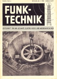
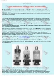
What does it look like?<br />
Here is a bird's-eye view of it.<br />
How well does it work?<br />
Once I got the mini-yagi mounted on my back deck and got it to resonate near 14.060 I took a set of SWR readings across the entire <strong>20</strong> meter<br />
band from below 14.000 to 14.350. <strong>The</strong> chart below shows my readings when mounted approximately 32 feet above ground, but with part of<br />
the elements only two feet above the slanted part of my rooftop.<br />
http://uts.cc.utexas.edu/~hansongr/<strong>Mini</strong>yagi.htm (4 of 5)2/5/<strong>20</strong>06 12:40:55 PM
<strong>The</strong> <strong>KJ5VW</strong> <strong>20</strong> <strong>Meter</strong> <strong>Mini</strong> <strong>Yagi</strong><br />
I was pleasantly surprised to see that the bandwidth between the SWR 2.0 points was more than <strong>20</strong>0 Khz. I had expected a much narrower<br />
bandwidth because of the wire elements and the inductive loading coils.<br />
When I connected the mini-yagi to my Emtech NW<strong>20</strong> transceiver the signals came roaring in. I heard WA9REQ calling CQ and gave him a<br />
shout. He came back on my first call and we exchanged 559 reports. I was very pleased. <strong>The</strong> yagi seemed to work. I signed with Dick and<br />
tuned around and heard KH6AFS in Hawaii calling CQ and even though the yagi was pointed north toward Illinois, I didn't take the time to run<br />
outside and rotate it by hand. I was astounded to get a 549 off the side of the mini-yagi and that was my first Hawaii contact. NOW, I was<br />
excited!<br />
I was off the air for almost two weeks before I could get back to further testing of my new antenna, but I decided to try and work a station or<br />
two every day for about a month and keep track of my signal reports.<br />
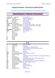
Signal Report Level Number of Contacts S/P/C<br />
599 3 CA, WY<br />
579 4 CA, IL, VE6,CO<br />
569 1 VE4<br />
559 8 IL,CA,PA,VK4,NY,IN<br />
549 6 HI,VE7,TN,PA<br />
339 1 CA<br />
Here's a table of the signal reports and the SPC's worked during the last two weeks of July and the first two weeks of August, 1997. As you can<br />
see the majority of my signal reports were in the 549 and 559 category, but nearly one-fourth were a 569 or higher. Working a VK4 in<br />
Australia on 5 watts was icing on the cake. Now, no one can tell me this simple little antenna doesn't work. I'm convinced!<br />
http://uts.cc.utexas.edu/~hansongr/<strong>Mini</strong>yagi.htm (5 of 5)2/5/<strong>20</strong>06 12:40:55 PM