

6 - 1 The Modified Computer Fan. Other more simple methods of ...
6 - 1 The Modified Computer Fan. Other more simple methods of ...
6 - 1 The Modified Computer Fan. Other more simple methods of ...

Create successful ePaper yourself
Turn your PDF publications into a flip-book with our unique Google optimized e-Paper software.
<strong>The</strong> <strong>Modified</strong> <strong>Computer</strong> <strong>Fan</strong>. <strong>Other</strong> <strong>more</strong> <strong>simple</strong> <strong>methods</strong> <strong>of</strong> getting this radiant energy charging <strong>of</strong><br />
batteries are also available. One <strong>simple</strong> method is to skip most <strong>of</strong> the mechanical construction and use a<br />
slightly adapted synchronous fan. This method is shown by “Imhotep” in his instructional video which is<br />
located at http://uk.youtube.com/watch?v=eDS9qk-Nw4M&feature=related. <strong>The</strong> original idea comes from<br />
John Bedini and the fan idea from Dr Peter Lindemann.<br />
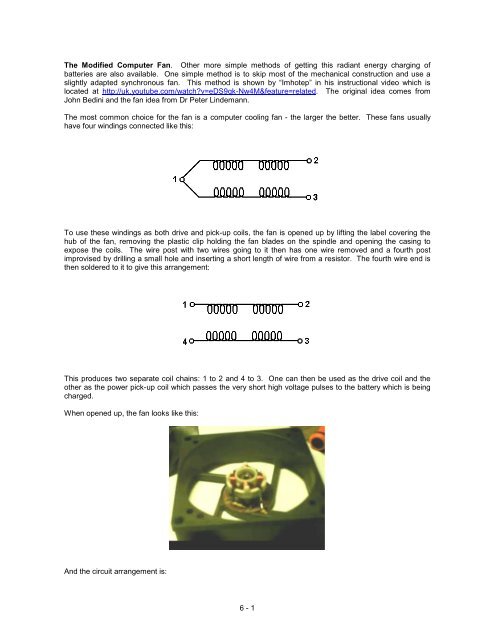
<strong>The</strong> most common choice for the fan is a computer cooling fan - the larger the better. <strong>The</strong>se fans usually<br />
have four windings connected like this:<br />
To use these windings as both drive and pick-up coils, the fan is opened up by lifting the label covering the<br />
hub <strong>of</strong> the fan, removing the plastic clip holding the fan blades on the spindle and opening the casing to<br />
expose the coils. <strong>The</strong> wire post with two wires going to it then has one wire removed and a fourth post<br />
improvised by drilling a small hole and inserting a short length <strong>of</strong> wire from a resistor. <strong>The</strong> fourth wire end is<br />
then soldered to it to give this arrangement:<br />
This produces two separate coil chains: 1 to 2 and 4 to 3. One can then be used as the drive coil and the<br />
other as the power pick-up coil which passes the very short high voltage pulses to the battery which is being<br />
charged.<br />
When opened up, the fan looks like this:<br />
And the circuit arrangement is:<br />
6 - 1
<strong>The</strong> fan is started by hand and then continues to spin, working as a fan as well as charging a battery. <strong>The</strong><br />
current draw from the driving battery is very low and yet the radiant energy charging <strong>of</strong> the other battery (or<br />
battery bank) is not slow. Please remember that batteries which are to be used with this radiant energy, need<br />
to be charged and discharged many times before they become adapted to working with this new energy.<br />
When that has been accomplished, the battery capacity is much greater than specified on the label <strong>of</strong> the<br />
battery and the recharging time also becomes much shorter. <strong>The</strong> circuit is adjusted with the variable resistor,<br />
which changes the transistor drive current, which in turn, alters the speed <strong>of</strong> the fan. <strong>The</strong> variable resistor<br />
setting is adjusted very slowly to find the resonant spot where the input current drops to a minimum. At<br />
resonant point, the battery charging will be at it's maximum level. It should be stressed that this device and<br />
the relay charger shown below, are <strong>simple</strong> demonstration devices with small coils and to get serious<br />
charging, you need to use one <strong>of</strong> John Bedini's large-coil battery pulsing systems with a bank <strong>of</strong> lead-acid<br />
batteries being charged.<br />
A very neat build <strong>of</strong> an 80 mm computer fan conversion to a pulse charger built by Brian Heath is shown<br />
here:<br />
<strong>The</strong> Car Relay Charger. An even <strong>more</strong> <strong>simple</strong> charging method is also shown by “Imhotep” in another <strong>of</strong> his<br />
instructional videos at http://d1190995.domaincentral.com.au/page6.html. Here he adapts an ordinary 40<br />
amp car relay, converting it from having a “normally open” contact, to operating with a “normally closed”<br />
contact. It is not necessary for you to do this as automotive relays with “normally closed” contacts are readily<br />
available and are not expensive.<br />
<strong>The</strong> relay is then wired up so that it powers itself through its own contacts. This causes a current to flow<br />
through the relay coil winding, operating the contact and opening it. This cuts <strong>of</strong>f the current through the<br />
relay’s own coil, causing the contacts to close again and the process starts all over again.<br />
<strong>The</strong> repeated opening and closing <strong>of</strong> the relay contacts happens at the resonant frequency <strong>of</strong> the relay and<br />
this produces a buzzing noise. Actually, buzzers were originally made this way and they were used in much<br />
the same way as a doorbell would be used today.<br />
<strong>The</strong> circuit used is shown here:<br />
6 - 2
As you can see, this very <strong>simple</strong> circuit uses only two components: one relay and one diode. <strong>The</strong> key feature<br />
is the fact that when the relay contacts open and current stops flowing through the relay coil, a very high<br />
voltage spike is generated across the relay coil. In transistor circuits which drive a relay, you will see a diode<br />
wired across the relay coil in order to short-circuit this high voltage at switch-<strong>of</strong>f and stop the transistor getting<br />
destroyed by the excessively high voltage. In this circuit, no protection is needed for the relay. Any number<br />
<strong>of</strong> batteries can be charged at the same time.<br />
An ordinary 40 amp automotive relay like this:<br />
can have a “changeover” contact, which means that it has a “normally closed” contact and so can be used<br />
directly without any need to open or modify the relay itself.<br />
In this circuit, however, that reverse voltage is being used in a very productive way. <strong>The</strong>se voltage spikes are<br />
very sharp, very short and have a very fast voltage rise. This is exactly what is needed to trigger an inflow <strong>of</strong><br />
radiant energy from the local environment, into the battery. This battery charging current is not coming from<br />
the driving battery but is coming from the environment. <strong>The</strong> small current from the driving battery is just<br />
operating the relay as a buzzer.<br />
Please remember that at this time, we have no instrument which can directly measure the flow <strong>of</strong> radiant<br />
energy into the charging battery. <strong>The</strong> only reliable way <strong>of</strong> assessing the inflow is to see how long it takes to<br />
discharge the charged battery through a known load.<br />
My experience with using relays for battery charging indicates that you get a better result if 24 volts is used to<br />
drive the circuit and as vehicle relays don’t have that much <strong>of</strong> a coil winding, there is a considerable<br />
improvement if a large coil is connected across the relay coil or coils as shown here:<br />
6 - 3
When using one <strong>of</strong> these relay charging systems you will find that quite a lot <strong>of</strong> noise is generated. This can<br />
be reduced quite easily with a little padding and it does have the advantage <strong>of</strong> indicating that the charging<br />
system is running correctly.<br />
6 - 4