Mini Card Interposer Datasheet - Teledyne LeCroy
Mini Card Interposer Datasheet - Teledyne LeCroy
Mini Card Interposer Datasheet - Teledyne LeCroy

You also want an ePaper? Increase the reach of your titles
YUMPU automatically turns print PDFs into web optimized ePapers that Google loves.
Protocol Solutions Group<br />
PProduct d t D<strong>Datasheet</strong> t h t<br />
<strong>Interposer</strong> Enables<br />
Testing of <strong>Mini</strong> <strong>Card</strong><br />
Designs and Probing of<br />
PCI Express p and USB<br />
2.0 Traffic with Quick,<br />
Simple Setup!<br />
Key Features<br />
■ Test new <strong>Mini</strong> <strong>Card</strong> designs and<br />
trouble-shoot existing designs<br />
■ Captures all PCI Express data<br />
traffic at data rates up to 5 GT/s<br />
■ Captures all USB traffic at data<br />
rates up to 480 Mb/s (USB 2.0)<br />
■ SSupports t connection ti to t a<br />
host <strong>Mini</strong> <strong>Card</strong> slot on a<br />
notebook computer or to a<br />
host PCI Express slot on a<br />
desktop computer<br />
Dimensions<br />
■ Board Dimensions:<br />
102 x 150 mm (4.0” x 5.9”)<br />
■ Cable Length for <strong>Mini</strong> <strong>Card</strong><br />
Connection (PE049UIA-X only):<br />
Standard <strong>Mini</strong> <strong>Card</strong> Adapter<br />
with 15 cm (6”) flexible cable<br />
Ordering Information<br />
Summit T28 Analyzer (x1 lane width) PE072AAA-X<br />
Voyager M3i USB 2.0 Advanced USB-TOA2-V02-X<br />
Analyzer System<br />
<strong>Mini</strong> <strong>Card</strong> <strong>Interposer</strong><br />
ffor<br />
PCI Express ® 2.0 and USB 2.0<br />
<strong>LeCroy</strong>’s new <strong>Mini</strong> C<strong>Card</strong><br />
<strong>Interposer</strong> supports development and test of small form<br />
factor I/O cards designed<br />
in compliance with <strong>Mini</strong> <strong>Card</strong> Electromechanical<br />
Specification Rev 1.22,<br />
developed by the PCI-SIG<br />
both PCI Express 2.0<br />
may use either or bo<br />
® . This specification provides for<br />
0 and USB 2.0 communication channels, and individual cards<br />
oth of these channels.<br />
The <strong>Mini</strong> <strong>Card</strong> Interpposer<br />
allows developers to probe new <strong>Mini</strong> <strong>Card</strong> designs and<br />
capture serial data trraffic<br />
using either a <strong>LeCroy</strong> PCI Express Analyzer or a <strong>LeCroy</strong><br />
USB Analyzer, Analyzer or bo booth<br />
oth. The analyzer(s) can be used to capture capture, decode and<br />
display all traffic on bboth<br />
serial data buses for troubleshooting, debugging and<br />
monitoring system performance.<br />
The <strong>Mini</strong> <strong>Card</strong> Interpposer<br />
can be physically configured in one of two ways: (1) as<br />
an extender board plugged<br />
(via a cable) into a host <strong>Mini</strong> <strong>Card</strong> slot (e.g., notebook<br />
environment) and ennables<br />
access to testing and probing of the <strong>Mini</strong> <strong>Card</strong>, or (2)<br />
with a standard PCI Express card slot to connect the <strong>Mini</strong> <strong>Card</strong> directly to the PCIe<br />
card slot (e.g., deskt<br />
<strong>Card</strong> <strong>Card</strong>. In this second<br />
The <strong>Mini</strong> <strong>Card</strong> Interp<br />
(PCIe 2.0). The card<br />
provides analyzer co<br />
and display of data t<br />
for use in debugging<br />
®<br />
top system) and yet still enable testing and probing of the <strong>Mini</strong><br />
mode mode, only PCI Express traffic will operate. operate<br />
poser supports x1 PCI Express at data rates of 5 GT/s<br />
d supports USB at data rates to 480 Mb/s (USB 2.0). The card<br />
onnections to <strong>LeCroy</strong> protocol analyzers for capture, decoding<br />
raffic. In addition, the interposer provides multiple test points<br />
g during development, production and test.<br />
<strong>Mini</strong> <strong>Card</strong> Gen2 x1 <strong>Interposer</strong> PE049UIA-X<br />
PE049UIA X<br />
(<strong>Mini</strong>-to-<strong>Mini</strong> connection, includes adapter cable<br />
and adapter card)<br />
<strong>Mini</strong> <strong>Card</strong> Gen2 x1 <strong>Interposer</strong> PE051UIA-X<br />
(<strong>Mini</strong>-to-PCIe slot connection)
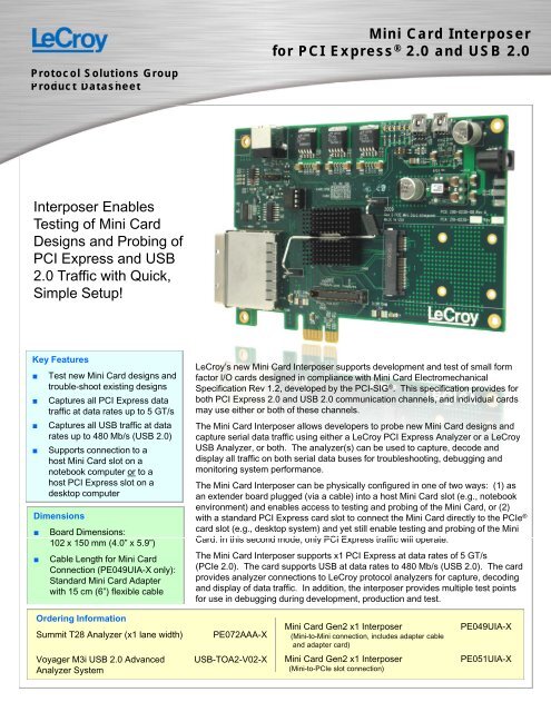
USB Port (used to configure card)<br />
<strong>Mini</strong> <strong>Card</strong><br />
<strong>Interposer</strong> p<br />
Layout<br />
PCI Express<br />
Analyzer<br />
Connection<br />
Configurations<br />
PCIe Edge <strong>Card</strong> Connection<br />
Cable Connector to Host <strong>Mini</strong> <strong>Card</strong> Slot<br />
<strong>Mini</strong>-to-<strong>Mini</strong> Configuration (PE049UIA-X)<br />
Adapter<br />
Cable<br />
<strong>Mini</strong> <strong>Card</strong><br />
Under Test<br />
Adapter<br />
<strong>Card</strong><br />
Host System<br />
<strong>Mini</strong> <strong>Card</strong><br />
Slot<br />
<strong>Mini</strong>-to-PCIe Slot Configuration g (PE051UIA-X)<br />
( )<br />
Host System PCIe Slot<br />
<strong>Mini</strong> <strong>Card</strong><br />
Under Test<br />
1-800-5-<strong>LeCroy</strong><br />
www.lecroy.com<br />
USB 1.1 <strong>Mini</strong>-B Poort<br />
for USB Analyzerr<br />
Tesst<br />
Poinnt<br />
Signal Description<br />
Open drain, active low signal that is driven low by a<br />
TP11<br />
WAKE# PCIe <strong>Mini</strong> <strong>Card</strong> function to reactivate the PCIe Link<br />
hierarchy’s main power rails and reference clocks.<br />
TP22<br />
TP33<br />
COEX1<br />
COEX2<br />
Provided to allow for the implementation of wireless<br />
coexistence solutions between the radio(s) on the <strong>Mini</strong><br />
<strong>Card</strong> and other off-card radio(s).<br />
RRequest that h the h PCI PCIe reference f clock l k bbe available il bl<br />
TP44<br />
CLKREQ# (active clock state) to allow the PCIe interface to<br />
send/receive data.<br />
User Identity Module power. Refer to ISO/IEC 7816-3<br />
TP55<br />
UIM_PWR for details on voltage and current requirements for the<br />
UIM_VPP power source for class A devices.<br />
TP66<br />
UIM_DATA<br />
This signal is used as output (UIM reception mode) or<br />
input (UIM transmission mode) for serial data.<br />
TP77<br />
UIM_CLK This signal provides the UIM card with the clock signal.<br />
TP88<br />
UIM_RESET This signal provides the UIM card with the reset signal.<br />
Reserved for future use for devices of other classes. classes<br />
TP99<br />
UIM_VPP<br />
Refer to ISO/IEC 7816-3 for more details on the voltage<br />
and current tolerance requirements for the UIM_VPP<br />
power source for class A devices.<br />
TP10<br />
TP11<br />
UIM_C8<br />
UIM_C4<br />
Reserved for future UIM interface (if needed)<br />
Provided for wireless communications add-in cards to<br />
TP12<br />
W_DISABLE#<br />
allow users to disable, via a system-provided switch, the<br />
add-in card’s radio operation in order to meet public<br />
safety regulations or when otherwise desired.<br />
TP1 3 PERST#<br />
De-asserted when the system power sources are within<br />
th their i specified ifi d voltage lt ttolerance l and d are stable. t bl<br />
TP14<br />
LED_WWAN# Three LED signals are provided to enable wireless<br />
communications add-in cards to provide status<br />
TP15<br />
LED_WAN#<br />
indications to users via system provided indicators.<br />
LED_WPAN#, LED_WLAN#, and LED_WWAN# output<br />
TP16<br />
LED_WPAN#<br />
signals are active low and are intended to drive systemmounted<br />
LED indicators.<br />
TP17<br />
INH#<br />
USB 2.0 <strong>Mini</strong>-B Port<br />
for USB Analyzer<br />
Local sales offices are located throoughout<br />
the world.<br />
Visit our website to find the most cconvenient<br />
location.<br />
DC Power<br />
Slot for<br />
<strong>Mini</strong> <strong>Card</strong><br />
Under Test<br />
System Compatibility<br />
Summit T28 <br />
Summit T3-8 <br />
Summit T3-16 <br />
Summit T2-16 <br />
Note: <strong>Card</strong> is<br />
preconfigured to use<br />
either PCIe card slot<br />
or cable to <strong>Mini</strong> <strong>Card</strong><br />
slot, but not both.<br />
<strong>Mini</strong> <strong>Card</strong><br />
I<strong>Interposer</strong> t TTest t PPoints i t<br />
The Inhibit pin for U9 (POL regulator for on-board 12Vto-3.8V)<br />
is an open-collector/drain-negative logic input<br />
that is referenced to GND. Applying a low-level Inhibit 5<br />
I ground signal to this input disables the module's<br />
output output. When the Inhibit control is active active, the input<br />
current drawn by the regulator is significantly reduced.<br />
©2011 by <strong>LeCroy</strong> Corporation. All rights reserved. Specifications, prices, availability and delivery subject to change without nootice.<br />
PSGMINICARDDS<br />
Product brand names and logos are trademarks or requested trademarks of their respective holders.<br />
05/11