Micro-Swiss Dicing Blades for 4"-Spindles - Minitron
Micro-Swiss Dicing Blades for 4"-Spindles - Minitron
Micro-Swiss Dicing Blades for 4"-Spindles - Minitron

Create successful ePaper yourself
Turn your PDF publications into a flip-book with our unique Google optimized e-Paper software.
e<br />
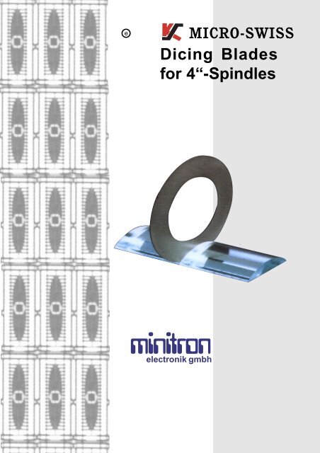
MICRO-SWISS<br />
<strong>Dicing</strong> <strong>Blades</strong><br />
<strong>for</strong> 4“-<strong>Spindles</strong><br />
minitron<br />
electronik gmbh
Industry Background<br />
Towards the year 2000 we face a new, complex set of<br />
demands as the microelectronics industry grows more<br />
sophisticated. Increasing miniaturzation of components<br />
depends on super accurate cutting. The use of very hard,<br />
brittle and exotic substrates creates special problems. The<br />
wide range of materials needs blades based on hard or<br />
soft binders with a choice of diamond particle sizes. Large<br />
volume production and high productivity rely on low,<br />
consistent blade wear, and in some cases, on specially<br />
designed accurate flange assemblies. All these demands<br />
are met by <strong>Micro</strong>-<strong>Swiss</strong> and our commitment to stay at the<br />
frontier of blade technology. This will also guarantee<br />
continued customer satisfaction.<br />
The Art of Successful Cutting<br />
The wide variety of materials to be cut today, and the high<br />
accuracy needed, require understanding and control of the<br />
cutting process. After choosing the correct blade, the most<br />
important step is dressing. While the resinoid blade requires<br />
minimum dressing due to the soft binder, the metal bond<br />
(nickel hubless) requires a longer dressing <strong>for</strong> free cutting<br />
and good kerf quality. Hub-type blades are predressed and<br />
there<strong>for</strong>e ready to go. Cooling is another very important<br />
parameter. Adequate cooling flow and nozzle proximity are<br />
a must <strong>for</strong> good kerf quality and long blade life. Additives<br />
in the cooling system are helpful in many applications. The<br />
correct exposure is crucial <strong>for</strong> blade stability and cut quality.<br />
Choosing the appropriate blade binder, diamond grit size,<br />
spindle speed and feed rate is essential <strong>for</strong> optimizing<br />
production yield, throughput and blade life.<br />
<strong>Micro</strong>-<strong>Swiss</strong> Hubless and Hub-Type<br />
<strong>Blades</strong><br />
<strong>Micro</strong>-<strong>Swiss</strong> offers a wide range of nickel hubless, resin<br />
hubless and nickel hub-type blades. Allblades fit the K&S<br />
780 saws, as well as those of most major competitors in<br />
the micro-electronic market.<br />
Nickel blades are recommended <strong>for</strong> cutting<br />
applications of TIC., P.Z.T., green ceramics and others.<br />
Resinoid blades are recommended <strong>for</strong> hard and brittle<br />
materials such as hard-alumina, glass, quartz, sapphire<br />
and others. Hub-type blades are used mainly <strong>for</strong> silicon<br />
and GaAs wafers. <strong>Micro</strong>-<strong>Swiss</strong> is currently working on<br />
secial requests <strong>for</strong> various binder characteristics to meet<br />
special application requirements.<br />
Process Control<br />
Consistency of blade per<strong>for</strong>mance is ensured by process<br />
control during blade manufacture. All <strong>Micro</strong>-<strong>Swiss</strong> blades<br />
undergo a strict 100% quality control, and are inspected<br />
using the most advanced testing methods. We also test<br />
our blades on K&S precision dicing systems, which provide<br />
a test bench to simulate the actual cutting process.<br />
2<br />
Titanium carbide bars diced with a nickel blade<br />
Figure 1<br />
Hub-type blade cutting a silicon wafer<br />
Figure 2<br />
Alumina substrate diced with a resinoid blade<br />
Figure 3<br />
Figure 4
Selection of Diamonds in Blade<br />
Manufacture<br />
To ensure superior kerf quality and long blade life,<br />
<strong>Micro</strong>-<strong>Swiss</strong> carefully controls the quality, purity, size<br />
and reliability of the diamond particles used in their<br />
blades. In nickel-bonded blades best results are<br />
obtained by using well-<strong>for</strong>med, strong, blocky, single<br />
crystal diamonds, (see figure 1).<br />
In resin-bonded blades friable diamond<br />
particles are used to achieve self-sharpening and<br />
free cutting action (see figure 2). The diamond<br />
particles are coated with a nickel alloy to improve<br />
the bond between the diamond and the resin. This<br />
coating also acts as a heat sink <strong>for</strong> heat generated<br />
during cutting.<br />
Figure 5<br />
Figure 6<br />
Choosing the Correct Diamond<br />
Particle Size<br />
The size of diamond particles to be used in cutting<br />
various materials is indicated in figure 4. This chart<br />
is only intended as a guide, because each<br />
customer`s needs are unique. <strong>Micro</strong>-<strong>Swiss</strong>, together<br />
with our 780 saw application lab offers a laboratory<br />
service to identify the ideal diamond size required<br />
<strong>for</strong> each customer`s application. The solution is tailormade,<br />
based on experiments which take into account<br />
the following parameters:<br />
Hardness and crystallographic structure of the<br />
material to be cut<br />
Depth of cut required<br />
Quality of cut required<br />
Throughput and feed rate<br />
Blade wear<br />
3<br />
Chemical analysis<br />
Figure 7<br />
Each <strong>Micro</strong>-<strong>Swiss</strong> blade is individually packed and marked<br />
with its production lot number to allow monitoring of in-use<br />
per<strong>for</strong>mance<br />
Figure 8<br />
Material<br />
Nickel<br />
( microns)<br />
Resinoid<br />
( microns)<br />
Alumina 45,<br />
53,<br />
63<br />
Ferrite 3-6 9<br />
Glass 45<br />
Garnet 35<br />
Barium Titanate<br />
45<br />
Kovar 53<br />
Quartz 30<br />
Silicon 2-4,<br />
3-6<br />
Germanium 3-6<br />
GaAs 2-4, 3-6<br />
9<br />
Sapphire 53-63<br />
Ruby 53<br />
Titanium Carbide<br />
3-6, 17,<br />
30<br />
53<br />
Piezoelectric ( PZT)<br />
3-6,<br />
10<br />
Lead Telluride<br />
3-6<br />
Alumina Nitride<br />
88,<br />
105<br />
Lithium Niobate<br />
3-6 25,<br />
30<br />
Figure 9
Flanges and Special Flange Sets<br />
Designed and Tailor made to Meet the Most<br />
Complicated Application Requirements<br />
<strong>Micro</strong>-<strong>Swiss</strong> engineers continually face new<br />
applications requiring unique, accurate gang<br />
assemblies to meet special throughput requirements.<br />
The flange sets are state-of-the-art designs<br />
machined to highest precision dimensions.<br />
Together with (or in addition to) special flange sets,<br />
<strong>Micro</strong>-<strong>Swiss</strong> supplies a wide range of standard<br />
flange sets, high cooling flange sets and lapping kits<br />
<strong>for</strong> improved maintenance of flange sets.<br />
The Best Results from the Best Saw-<br />
Blade Combination<br />
Best cutting results come from perfect compatibility<br />
between machine and tools. <strong>Micro</strong>-<strong>Swiss</strong> nickelbonded<br />
and resin-bonded blades were beveloped<br />
along with the 780 series of saws.<br />
They are manufactured by the K&S <strong>Micro</strong>-<strong>Swiss</strong><br />
team of dedicated engineers and technicians. Quality<br />
control and maximum reliability are obtained through<br />
testing in our own 780 cutting laboratory.<br />
Finally, many complex and high volume applications<br />
of the blades and saws in use by customers prove<br />
the success of this perfect combination.<br />
4<br />
A titanium 2“ flange set with 7 x .001“ nickel blades<br />
Figure 10<br />
Metric dimensions are approximate. All specifications are subject to change without notice.<br />
Figure 11
NICKEL BLADE SELECTION<br />
4.256“ O.D. x 3.500“ I.D. (108,10 mm x 88,90 mm)<br />
4.600“ O.D. x 3.500“ I.D. (116,84 mm x 88,90 mm)<br />
Diamond-<br />
Grit<br />
Mic.<br />
3-6<br />
10<br />
17<br />
30<br />
50<br />
70<br />
Thickness Range<br />
Blade<br />
mm0, 030-0,<br />
036<br />
0, 036-0,<br />
041<br />
0, 041-0,<br />
051<br />
0, 051-0,<br />
063<br />
0, 063-0,<br />
076<br />
0, 076-0,<br />
102<br />
0, 102-0,<br />
127<br />
0, 127-0,<br />
178<br />
0, 178-0,<br />
229<br />
0, 229-0,<br />
279<br />
0, 279-0,<br />
330<br />
0,<br />
330-0,<br />
381<br />
O.<br />
D.<br />
inc-<br />
. 0012-.<br />
0014<br />
. 0014-.<br />
0016<br />
. 0016-.<br />
0020<br />
. 0020-.<br />
0025<br />
. 0025-.<br />
0030<br />
. 0030-.<br />
0040<br />
. 0040-.<br />
0050<br />
. 0050-.<br />
0070<br />
. 0070-.<br />
0090<br />
. 0090-0110<br />
. 0110-.<br />
0130<br />
. 0130-.<br />
0150<br />
inch mm<br />
h<br />
K & S 12 DIGIT PART NUMBER 00 776 - 4 5 0 1 - 090<br />
NICKEL<br />
BINDER<br />
4. 256"<br />
O.<br />
D.<br />
1<br />
4. 600"<br />
O.<br />
D.<br />
4<br />
012 014 016 020 025 030 040 050 070 090 110 130<br />
Figure 12<br />
* 4.600“ O.D. blades, over .009“ thick, are predressed<br />
as standard.<br />
All other blades, .005“ and thicker, can be<br />
supplied pre-dressed on request.<br />
All blades are 3.500“ (88,90 mm) I.D. to fit K&S<br />
flage sets.<br />
All blade thicknesses, diamond grit sizes and<br />
diameters are available on request.<br />
5<br />
BLADE THICKNESS<br />
0<br />
1<br />
Not Available as standard<br />
REGULAR<br />
BLADE<br />
PRE<br />
DRESSED<br />
BLADE<br />
DIAMOND<br />
GRIT<br />
SIZES<br />
2 3-6<br />
Mic.<br />
3 10<br />
Mic.<br />
4 17<br />
Mic.<br />
5 30<br />
Mic.<br />
6 50<br />
Mic.<br />
7 70<br />
Mic.<br />
Pre-dressed Blade<br />
Flat blade edge with diamond exposed<br />
Figure 13<br />
4. 256"<br />
108,<br />
10<br />
4. 600"<br />
116,<br />
84<br />
4. 256"<br />
108,<br />
10<br />
4. 600"<br />
116,<br />
84<br />
4. 256"<br />
108,<br />
10<br />
4. 600"<br />
116,<br />
84<br />
4. 256"<br />
108,<br />
10<br />
4. 600"<br />
116,<br />
84<br />
4. 256"<br />
108,<br />
10<br />
4. 600"<br />
116,<br />
84<br />
4. 256"<br />
108,<br />
10<br />
4. 600"<br />
116,<br />
84
NICKEL SERRATED BLADE SELECTION<br />
4.256“ O.D. x 3.500“ I.D. (108,10 mm x 88,90 mm)<br />
4.600“ O.D. x 3.500“ I.D. (116,84 mm x 88,90 mm)<br />
Diamond<br />
Grit<br />
Mic.<br />
3-6<br />
10<br />
17<br />
30<br />
50<br />
70<br />
NICKEL<br />
BINDER<br />
4. 256"<br />
O.<br />
D.<br />
1<br />
4. 600"<br />
O.<br />
D.<br />
4<br />
Thickness<br />
Range<br />
mm0, 127-0,<br />
178<br />
0, 178-,<br />
. 229<br />
0, 229-0,<br />
279<br />
0, 279-0,<br />
330<br />
0,<br />
330-0,<br />
381<br />
inch . 0050-.<br />
0070<br />
. 0070-.<br />
0090<br />
. 0090-.<br />
0110<br />
. 0110-.<br />
0130<br />
. 0130-.<br />
0150<br />
Figure 14<br />
050 070 090 110 130<br />
K & S 12 DIGIT PART NUMBER 00 776 - 4 5 1 1 - 110<br />
* 4.600“ O.D. blades, over .009“ thick, are predressed<br />
as standard.<br />
All other blades can be supplied pre-dressed on<br />
request.<br />
Serrated blades are designed <strong>for</strong> freer cutting with<br />
less load. The slots eliminate continuous blade<br />
and material contact and improve blade and<br />
substrate cooling.<br />
4.256“ O.D. blades are available up to .0130“<br />
thickness as standad.<br />
Available on request are blades with different<br />
blade thickness, diamond grit size, slot geometry<br />
and number of slots.<br />
6<br />
4.256“ O.D.<br />
54 slots<br />
.040 (1,00 mm) wide<br />
.100“ (2,54 mm) deep<br />
4.600“ O.D.<br />
60 slots<br />
.050“ (1,27 mm) wide<br />
.100“ (2,54 mm) deep<br />
BLADE THICKNESS<br />
0<br />
1<br />
Figure 15<br />
REGULAR<br />
BLADE<br />
PRE<br />
DRESSED<br />
BLADE<br />
SERRATED<br />
TYPE<br />
DIAMOND<br />
GRIT<br />
SIZES<br />
4 17<br />
Mic.<br />
5 30<br />
Mic.<br />
6 50<br />
Mic.<br />
7 70<br />
Mic.<br />
*
NICKEL SERRATED BLADE SELECTION<br />
5.000“ O.D. x 3.500“ I.D. (127,00 mm x 88,90 mm)<br />
5.000“ O.D. x 3.000“ I.D. (127,00 mm x 76,20 mm)<br />
3. 500"<br />
O.<br />
D.<br />
0<br />
3. 000"<br />
O.<br />
D.<br />
5<br />
NICKEL<br />
BINDER<br />
Diamond<br />
Grit<br />
Mic.<br />
5 30<br />
6 50<br />
7 70<br />
Figure 16<br />
* All blades are pre-dressed as standard.<br />
Serrated blades are designed <strong>for</strong> freer cutting with<br />
less load. The slots eliminate continuous blade<br />
and material contact and improve blade and<br />
substrate cooling.<br />
<strong>Blades</strong> are 3.500“ (88,90mm) and 3.000“<br />
(76,20mm) I.D. to fit K&S flange sets.<br />
Available on request are blades with different<br />
blade thickness, diamond grit size, slot geometry<br />
and number of slots.<br />
Thickness<br />
Range<br />
mm0, 229-0,<br />
279<br />
0, 279-0,<br />
330<br />
0,<br />
330-0,<br />
381<br />
inch . 009-.<br />
011<br />
. 011-.<br />
013<br />
. 013-.<br />
015<br />
090 110 130<br />
7<br />
BLADE THICKNESS<br />
K & S 12 DIGIT PART NUMBER 0 5 776 - 5 5 1 1 - 110<br />
PRE<br />
DRESSED<br />
BLADE<br />
5<br />
SERRATED<br />
TYPE<br />
Figure 17<br />
5.<br />
000"<br />
O.<br />
D.<br />
.600“ thick green ceramic substrate cut<br />
through with 5.000“ O.D. nickel<br />
serrated blade.<br />
*
RESINOID BLADE SELECTION<br />
4.256“ O.D. x 3.500“ I.D. (108,10 mm x 88,90 mm)<br />
4.600“ O.D. x 3.500“ I.D. (116,84 mm x 88,90 mm)<br />
*<br />
Diamond<br />
Thickness<br />
Range<br />
Grit<br />
Mic.<br />
mm0, 076<br />
0, 102<br />
0, 127<br />
0, 152<br />
0, 178<br />
0, 203<br />
0, 229<br />
0, 254<br />
0, 279<br />
0, 305<br />
0, 330<br />
0, 356<br />
0, 381<br />
0, 406<br />
0, 432<br />
0, 457<br />
0, 483<br />
0, 508<br />
0, 635<br />
0, 762<br />
0, 889<br />
1, 016<br />
1, 143<br />
1,<br />
270<br />
Mic. Mesh inch . 003<br />
. 004<br />
. 005<br />
. 006<br />
. 007<br />
. 008<br />
. 009<br />
. 010<br />
. 011<br />
. 012<br />
. 013<br />
. 014<br />
. 015<br />
. 016<br />
. 017<br />
. 018<br />
. 019<br />
. 020<br />
. 025<br />
. 030<br />
. 035<br />
. 040<br />
. 045<br />
. 050<br />
6 3000<br />
9 1800<br />
151200 201000 25800 30600 35400 45325 53270 63230 86170 105 140<br />
**<br />
0<br />
1<br />
2<br />
REGULAR<br />
BLADE<br />
SERRATED<br />
TYPE<br />
SHAPED<br />
EDGE<br />
RESINOID<br />
BINDER<br />
Figure 18<br />
DIAMOND GRIT<br />
BLADE THICKNESS<br />
K & S 12 DIGIT PART NUMBER 0 0 777 - 6 0 53 - 010<br />
* <strong>Blades</strong> .015“ (0,381mm) and thicker can be<br />
supplied serrated.<br />
Please consult factory.<br />
** <strong>Blades</strong> .020“ (0,508mm) and thicker can be<br />
supplied with special edge geometry.<br />
Please consult factory.<br />
All blades are 3.500“ (88,90mm) I.D. to fit K & S<br />
flange sets.<br />
Available on request are blades with different<br />
blade thickness and diamond grid size.<br />
<strong>Blades</strong> are electrically conductive.<br />
8<br />
Not Available.<br />
Large diamond<br />
particles will produce<br />
oversized blade<br />
thickness.<br />
2 4.<br />
256"<br />
O.<br />
D.<br />
6 4.<br />
600"<br />
O.<br />
D.<br />
Ferrite application with 4.600“ O.D. resinoid blade.<br />
Figure 19
RESINOID COARSE FINE COMPOSITION - BLADE SELECTION<br />
4.256“ (108,10 mm) O.D. x 3.500“ I.D. (88,90 mm) I.D.<br />
4.600“ (116,84 mm) O.D. x 3.500“ I.D. (88,90 mm) I.D.<br />
Fine<br />
Diamond<br />
Thickness<br />
Range<br />
Grit<br />
mm0, 203<br />
0, 229<br />
0, 254<br />
0, 279<br />
0, 305<br />
0, 330<br />
0, 356<br />
0, 381<br />
0, 406<br />
0, 432<br />
0, 457<br />
0, 483<br />
0, 508<br />
0, 635<br />
0, 762<br />
0, 889<br />
1, 016<br />
1, 143<br />
1,<br />
270<br />
9<br />
Coarse<br />
Diamond<br />
Grit<br />
Mic. Mesh inch . 008<br />
. 009<br />
. 010<br />
. 011<br />
. 012<br />
. 013<br />
. 014<br />
. 015<br />
. 016<br />
. 017<br />
. 018<br />
. 019<br />
. 020<br />
. 025<br />
. 030<br />
. 035<br />
. 040<br />
. 045<br />
. 050<br />
Mic. Mesh<br />
6 3000 30600 9 1800 35400 15 1200 45325 20 1000 53270 25 800 63230 30 600 88170 35 400 105 140<br />
K & S 12 DIGIT PART NUMBER 0 3 777 - 6 0 63 - 012<br />
COARSE/<br />
FINE<br />
COMPOSITION<br />
RESINOID<br />
BINDER<br />
When ordering please specify the following:<br />
Blade O.D.<br />
Total blade thickness<br />
Fine and coarse grits.<br />
* P/N includes only the coarse grit<br />
BLADE THICKNESS<br />
All blades are 3.500“ (88,90 mm) I.D. to fit K & S flange sets.<br />
Available on request are blades with different blade thickness<br />
and diamond grit size.<br />
Cutting very brittle materials requires a very fine diamond grit to<br />
minimize chipping. Fine diamond grit blades have a higher blade<br />
wear and can only cut with very low feed rates.<br />
In some applications, Kulicke and Soffa state-of-the-art resinoid<br />
coarse/fine composition blade is the answer.<br />
The coarse center of the blade per<strong>for</strong>ms as the majority stock<br />
remover, and the finer, outer layers provide the fine chip-free<br />
kerf edge.<br />
Selecting blade composition<br />
Selecting the right blade composition is an experimental<br />
process <strong>for</strong> every customer based on the following parameters:<br />
Hardness and crystallographic structure of the material to<br />
be cut.<br />
Depth of cut.<br />
Quality of kerf edge required.<br />
Throughhput and feed rate.<br />
Blade wear.<br />
COARSE DIAMOND GRIT *<br />
2 4.<br />
256"<br />
O.<br />
D.<br />
6 4.<br />
600"<br />
O.<br />
D.<br />
.002"-.003" .004" min<br />
.002"-.003"<br />
fine grit<br />
chip free kerf edge<br />
Figure 20<br />
Figure 21<br />
coarse grit<br />
fine grit<br />
chip free kerf edge
FIBER REINFORCED RESINOID BLADE SELECTION<br />
4.700“ O.D. x 3.500“ I.D. (119,38 mm x 88,90 mm)<br />
Diamond<br />
Thickness<br />
Range<br />
Grit<br />
Mic.<br />
mm0, 203<br />
0, 229<br />
0, 254<br />
0, 279<br />
0, 305<br />
0, 330<br />
0, 356<br />
0, 381<br />
0, 406<br />
0, 432<br />
0, 457<br />
0, 483<br />
0, 508<br />
0, 635<br />
0, 762<br />
0, 889<br />
1, 016<br />
1, 143<br />
1,<br />
270<br />
Mic. Mesh inch . 003<br />
. 009<br />
. 010<br />
. 011<br />
. 012<br />
. 013<br />
. 014<br />
. 015<br />
. 016<br />
. 017<br />
. 018<br />
. 019<br />
. 020<br />
. 025<br />
. 030<br />
. 035<br />
. 040<br />
. 045<br />
. 050<br />
151200 201000 25800 30600 35400 45325 53270 63230 86170 105 140<br />
FIBER<br />
REINFORCED<br />
RESINOID<br />
BINDER<br />
Figure 22<br />
K & S 12 DIGIT PART NUMBER 0 7 777 - 7 0 53 - 020<br />
Rein<strong>for</strong>ced blades are made with fiberglass mesh<br />
laminated in the center. The fiberglass mesh adds<br />
flexural strength which allows <strong>for</strong> more blade<br />
exposure.<br />
These special 4.700“ O.D. blades are designed <strong>for</strong><br />
deeper cuts where large exposure is needed.<br />
All blades are 3.500“ (88.9mm) I.D. to fit K & S<br />
flange sets.<br />
Available on request are blades with different O.D.,<br />
blade thickness, and diamond grit size.<br />
10<br />
.008" min<br />
Not Available<br />
4.<br />
700"<br />
Fiberglass mesh rein<strong>for</strong>ced<br />
Figure 23<br />
O.<br />
D.
FLANGE SELECTION FOR<br />
4.256“ (108,10 mm), 4.600“ (116.84 mm)<br />
and 5.000“ (127,00 mm) BLADE O.D.<br />
x 3.500“ (88,90 mm) Blade I.D., <strong>for</strong> 1.250“ (31,75 mm) SPINDLE O.D.<br />
4"<br />
FLANGE<br />
FOR<br />
1.<br />
250"<br />
SPINDLE<br />
FLANGE<br />
FOR<br />
3.<br />
500"<br />
I.<br />
D.<br />
BLADE<br />
EXPOSURE<br />
FLANGE<br />
O.<br />
D.<br />
P/<br />
N<br />
4 . 256"<br />
4 . 600"<br />
5.<br />
000"<br />
INCH mm INCH mm INCH mm INCH mm<br />
785-3515-000 4. 550<br />
115, 57<br />
X X . 025<br />
0, 63<br />
. 220<br />
5,<br />
59<br />
785-3514-000 4. 500<br />
114, 30<br />
X x . 050<br />
1, 27<br />
. 250<br />
6,<br />
35<br />
785-3513-000 4. 450<br />
113, 03<br />
X X . 075<br />
1, 90<br />
. 275<br />
6,<br />
98<br />
785-3512-000 4. 400<br />
111, 76<br />
X X . 100<br />
2, 54<br />
. 300<br />
7,<br />
62<br />
785-3511-000 4. 350<br />
110, 49<br />
X X . 125<br />
3, 17<br />
. 325<br />
8,<br />
25<br />
785-3510-000 4. 300<br />
109, 22<br />
X X . 150<br />
3, 81<br />
. 350<br />
8,<br />
89<br />
785-3509-000 4. 260<br />
108, 20<br />
X X . 170<br />
4, 32<br />
. 370<br />
9,<br />
40<br />
785-3508-000 4. 236<br />
107, 59<br />
. 010<br />
0, 25<br />
. 182<br />
4, 62<br />
. 382<br />
9,<br />
70<br />
785-3507-000 4. 220<br />
107, 19<br />
. 018<br />
0, 45<br />
. 190<br />
4, 83<br />
. 390<br />
9,<br />
90<br />
785-3506-000 4. 213<br />
107, 01<br />
. 022<br />
0, 56<br />
. 194<br />
4, 93<br />
. 393<br />
9,<br />
98<br />
785-3505-000 4. 200<br />
106, 68<br />
. 028<br />
0, 71<br />
. 200<br />
5, 08<br />
. 400<br />
10,<br />
16<br />
785-3504-000 4. 180<br />
106, 17<br />
. 038<br />
0, 96<br />
. 210<br />
5, 33<br />
. 410<br />
10,<br />
41<br />
785-3503-000 4. 140<br />
105, 15<br />
. 058<br />
1, 47<br />
. 230<br />
5, 84<br />
. 430<br />
10,<br />
92<br />
785-3502-000 4. 100<br />
104, 14<br />
. 078<br />
1, 98<br />
. 250<br />
6, 35<br />
. 450<br />
11,<br />
43<br />
785-3501-000 4. 000<br />
101, 60<br />
. 128<br />
3, 25<br />
. 300<br />
7, 62<br />
. 500<br />
12,<br />
70<br />
K & S 12 DIGIT PART NUMBER 00 785 - 35 XX - 00 0<br />
Part No. <strong>for</strong> Bushing: 775-8711-001<br />
Part No. <strong>for</strong> Bushing Nut: 775-8711-002<br />
FLANGE SERIAL NO.<br />
The above flange list is the K & S standard O.D. size<br />
list. Other O.D. sizes and special flanges <strong>for</strong> thick<br />
blades or double blade assemblies are available on<br />
request.<br />
11<br />
Figure 24<br />
1. Front Flange<br />
2. Back Flange<br />
3. Bushing<br />
4. Bushing Nut<br />
Figure 25<br />
0 FLANGE<br />
ASSEMBLY<br />
1 FRONT<br />
FLANGE<br />
ONLY<br />
2 BACK<br />
FLANGE<br />
ONLY<br />
2 1 4 3
HIGH COOLING FLANGE SELECTION FOR<br />
4.600“ (116,84 mm), and 5.000“ (127,00 mm) BLADES O.D.<br />
x 3.500“ (88,90 mm) Blade I.D.<br />
4"<br />
FLANGE<br />
FOR<br />
1.<br />
250"<br />
SPINDLE<br />
HIGH<br />
COOLING<br />
FLANGE<br />
P/<br />
N<br />
FLANGE<br />
O.<br />
D.<br />
12<br />
EXPOSURE<br />
4 . 600"<br />
5.<br />
000"<br />
INCH mm INCH mm INCH mm<br />
785-3911-000 4. 55<br />
115, 57<br />
. 025<br />
0, 63<br />
. 220<br />
5,<br />
59<br />
785-3910-000 4. 50<br />
114, 30<br />
. 050<br />
1, 27<br />
. 250<br />
6,<br />
35<br />
785-3909-000 4. 45<br />
113, 03<br />
. 075<br />
1, 90<br />
. 275<br />
6,<br />
98<br />
785-3908-000 4. 40<br />
111, 76<br />
. 100<br />
2, 54<br />
. 300<br />
7,<br />
62<br />
785-3907-000 4. 35<br />
110, 49<br />
. 125<br />
3, 17<br />
. 325<br />
8,<br />
25<br />
785-3906-000 4. 30<br />
109, 22<br />
. 150<br />
3, 81<br />
. 350<br />
8,<br />
89<br />
785-3905-000 4. 25<br />
107, 95<br />
. 175<br />
4, 44<br />
. 375<br />
9,<br />
52<br />
785-3904-000 4. 20<br />
106, 68<br />
. 200<br />
5, 08<br />
. 400<br />
10,<br />
16<br />
785-3903-000 4. 15<br />
105, 41<br />
. 225<br />
5, 71<br />
. 425<br />
10,<br />
79<br />
785-3902-000 4. 10<br />
104, 14<br />
. 250<br />
6, 35<br />
. 450<br />
11,<br />
43<br />
785-3901-000 4. 00<br />
101, 60<br />
. 300<br />
7, 62<br />
. 500<br />
12,<br />
70<br />
FLANGE SERIAL NO.<br />
K & S 12 DIGIT PART NUMBER 00 785 - 39 XX - 00 0<br />
Part No. <strong>for</strong> Bushing: 775-8711-001<br />
Part No. <strong>for</strong> Bushing Nut 775-3725-002<br />
High cooling flange sets are designed <strong>for</strong> better<br />
cooling of the blade and the substrate which results<br />
in better cut quality and blade life.<br />
For installation of high cooling flange please consult<br />
factory.<br />
The above flange list is the K & S standad O.D. size<br />
list.<br />
Other O.D. sizes are available on request.<br />
Figure 26<br />
1. Front Flange<br />
2. Back Flange<br />
3. Bushing<br />
4. Bushing Nut<br />
0 FLANGE<br />
ASSEMBLY<br />
1 FRONT<br />
FLANGE<br />
ONLY<br />
2 BACK<br />
FLANGE<br />
ONLY<br />
2 1 4 3<br />
Figure 27
Principles of <strong>Dicing</strong><br />
Background<br />
Gideon Levinson<br />
<strong>Dicing</strong> Tools Product Manager<br />
<strong>Dicing</strong> (or diamond-wheel sawing) is used in the<br />
microelectronics industry <strong>for</strong> die separation and also<br />
<strong>for</strong> fine, accurate, partial and cut-through of exotic,<br />
very hard and brittle materials. The wide range of<br />
materials processed makes it necessary to use<br />
different blades. These may be based on hard or soft<br />
binders, with various diamond particle sizes. Largescale<br />
production and high productivity rely on low,<br />
consistent blade wear as demanded by today´s<br />
sophisticated industrial environment<br />
History and other separating<br />
techniques<br />
Other techniques have been used, mainly <strong>for</strong> die<br />
separation.<br />
Diamond scribing<br />
This is the oldest separating method, mainly used<br />
<strong>for</strong> silicon wafers. In Figure 1 a diamond tip, with an<br />
angle of about 125°, scribes a shallow scratch on<br />
the wafer.<br />
The edge quality of a scribed and broken die is poor.<br />
Breaking produces dies that are irregular in size and<br />
shape.<br />
125˚<br />
Break Line<br />
Figure 28: Diamond Scribe<br />
Silicon<br />
Wafer<br />
13<br />
Laser scribing<br />
This technique is used mainly to separate hard<br />
alumina substrates.<br />
In laser scribing, a laser beam moves rapidly along<br />
a street producing cone shaped per<strong>for</strong>ations. The<br />
dies are then broken apart, as in diamond scribing.<br />
The edge of a laser-cut die is not smooth because<br />
the scribe-line consists of a series of holes burned<br />
out of the top of the substrate. Mechanical and<br />
cosmetic edge quality are limitations in laser scribing<br />
(Figure 2). Laser scribing is a fast technique and is<br />
being used in large-scale production where quality<br />
is not the main consideration.<br />
Break<br />
Diamond wheel dicing<br />
Slag<br />
Resolidified<br />
Contaminants<br />
Hard Substrate<br />
Figure 2: Laser Scribe<br />
This is the most common technique in the industry.<br />
The cut quality is higher than other techniques. Also,<br />
it is possible to keep cut width, depth, and<br />
straightness as well as edge quality under tight<br />
control (Figure 3).<br />
Edge<br />
Quality<br />
Figure 30: <strong>Dicing</strong> with Diamond Blade<br />
Cut Width<br />
Cut Depth
Blade Basics<br />
A diamond blade is actually a ring composed of<br />
abrasive grains (diamond particles) held together by<br />
a binder - either nickel or phenolic resin or metalpowder<br />
sintering.<br />
Each individual diamond particle acts as a singlepoint<br />
tool, pushing a chip of material ahead of it. As<br />
there are many diamond particles on a blade edge,<br />
there are there<strong>for</strong>e many single-point tools pushing<br />
out the substrate and creating a kerf (Figure 4.)<br />
Diamond<br />
Particle<br />
Chuck Saw Feed<br />
Rotation<br />
Figure 31<br />
Blade<br />
Chip<br />
Substrate<br />
Blade binders<br />
Materials used nowadays in the microelectronics<br />
industry exhibit a wide range of hardnesses, from<br />
relatively soft to extremely hard and brittle. This large<br />
variety requires a range of soft and hard blade<br />
binders.<br />
A hard and brittle material requires a soft blade<br />
binder. A phenolic resin binder is used on those<br />
materials to archieve free cutting action, with very<br />
fine chip-free kerfs. Cutting per<strong>for</strong>mance is based<br />
on the binder´s ability to release dulled diamonds<br />
and expose, new sharp ones at the same time.<br />
On softer, less brittle substrates a harder matrix is<br />
necessary. Nickel and metal sintered binders are<br />
normally used tor these applications. The nickel-type<br />
blade is a state-of-the-art electro<strong>for</strong>med product. It<br />
has a very hard nickel matrix, with diamonds<br />
distributed homogeneously through it. This bond is<br />
the key <strong>for</strong> very low wear.<br />
Choosing the right binder is a matter of experience.<br />
See page 3 <strong>for</strong> a blade selection table; however, as<br />
each application is unique, it should de used only<br />
as a guideline. Final selection should be done only<br />
after the process has been optimized in production<br />
mode.<br />
14<br />
Diamond selection<br />
It is important to control the quality, purity, size and<br />
reliability of the diamond particles in order to ensure<br />
superior kerf quality and long blade life. With nickelbonded<br />
blades the best results are obtained by using<br />
well-<strong>for</strong>med, strong, blocky, single-crystal diamonds.<br />
In resin-bonded blades friable diamond particles are<br />
used to achieve self-sharpening, free cutting action.<br />
The diamond particles are coated with a nickel alloy<br />
in order to improve the diamond-resin bond. The<br />
coating also sinks the heat generated during cutting.<br />
Again, selecting the right diamond size <strong>for</strong> each<br />
application is a matter of experience and process<br />
optimization. See page 3 <strong>for</strong> general guidelines.<br />
Blade and substrate cooling<br />
Cooling of the blade and the substrate is basic and<br />
essential <strong>for</strong> any dicing application.<br />
Following are the main basic points to be aware of:<br />
• Alignment of the cooling nozzles with the blade<br />
and substrate.<br />
Front View Side View<br />
Figure 32: Front View and Side View<br />
Water Stream<br />
• Cooling pressure - consult the recommendations<br />
of the manufacturer of the saw<br />
• The ability of the blade to cool itself. We have<br />
discussed this when mentioning blade binders,<br />
resin bond. More on this in the section about blade<br />
dressing.<br />
Cutting heavy substrates .100 to .500 thick creates<br />
cooling and overloading problems. Nozzle alignment<br />
and coolant pressure are not the only solutions. A<br />
serrated blade is used <strong>for</strong> these applications.
The serrated blades are designed <strong>for</strong> freer cutting<br />
with less load. The slots eliminate continuous contact<br />
between blade and material, and improve cooling of<br />
both blade and substrate. Nickel serrated blades are<br />
a standard product. Resinoid serrated blades can<br />
be made on request.<br />
Advantages and disadvantages of serrated blades<br />
Advantages<br />
1. Less contact between edge and substrate, which<br />
translates into less load during cutting.<br />
2. Better cooling, due to serrations.<br />
Disadvantages<br />
Kerf width is not as accurate as with regular blades.<br />
Some vibrations.<br />
Another solution <strong>for</strong> cooling blades on heavy<br />
substrates is the K&S high cooling flange (Figure<br />
10). This unique design spreads the coolant from<br />
the center of the flange to the outer edge of the blade<br />
on both of its sides. The high velocity (spindle r.p.m.)<br />
translates into high pressure on the coolant, which<br />
is <strong>for</strong>ced to the bottom of the kerf.<br />
Cooling<br />
Nozzle<br />
Some Vibrations<br />
Figure 33<br />
Figure 34<br />
15<br />
The high cooling flange makes a standard cooling<br />
nozzle unnecessary.<br />
Dressing<br />
One of the most important steps to assure accurate<br />
dicing is dressing the blade be<strong>for</strong>e cutting. Dressing<br />
is important <strong>for</strong> the following reasons:<br />
• Excess binder material or loose diamond<br />
particles are machined off.<br />
• The binder holding the diamonds is machined<br />
off, exposing the diamonds<br />
• It trues the outside diameter runout<br />
• It trues the blade edge geometry.<br />
• Minimizes the load, creates a cooler and freer<br />
cut.<br />
Dressing techniques<br />
The best method is grinding the blade in the same<br />
flange that is being used on the saw. This will result<br />
in a perfect runout of the blade on the saw.<br />
Grinding can be done on a cylindrical grinder (Figure<br />
13) or on a dressing machine. The dressing wheel<br />
used is a silicon carbide type, with about 320 mesh.<br />
Figure 35<br />
Our standard nickel heavy blades (over .009“ thick)<br />
are predressed. However, <strong>for</strong> a perfect runout and<br />
better per<strong>for</strong>mance, it is important to grind them as<br />
mentioned.<br />
Resinoid blades require minimum dressing because<br />
of their soft binder and their ability to self-dress. For<br />
most applications, a resinoid blade may be used<br />
without special dressing requirements.<br />
mswbl4-2.05, 04-98