MZ-G/MG - Mold-Masters
MZ-G/MG - Mold-Masters
MZ-G/MG - Mold-Masters

You also want an ePaper? Increase the reach of your titles
YUMPU automatically turns print PDFs into web optimized ePapers that Google loves.
<strong>MZ</strong>-G/<strong>MG</strong><br />
user manual<br />
revision 1.4<br />
www.moldmasters.com<br />
E3540-1 G/<strong>MG</strong> MAN v1.4
Amendments Record <strong>MZ</strong>-G/<strong>MG</strong> Manual<br />
Amendments Record<br />
Issue Date<br />
dd/mm/yy<br />
Page 2<br />
Amendments Author Authorized<br />
1.0 05/03/02 First formal Issue DT JN<br />
1.1 01/05/02 • Run controls moved to main Display page.<br />
• EasyView mini-panel display controls changed.<br />
• New remote option for Boost or Standby.<br />
• New “Master Only Startup” mode introduced.<br />
• Utilities – Mode subpage removed.<br />
• Boost & Standby controls moved from Global to<br />
autonomous zones.<br />
DT JN<br />
1.2 27/01/03 • Add I/O & 30A Mod card description.<br />
• Add T/C & Power Output, and Plug configuration<br />
diagram in Appendix A.<br />
• Add Spare Part List<br />
DT JN<br />
1.3 28/10/03 • Combine G/<strong>MG</strong> manual<br />
• Introduce new “Easyset” in Setup Page<br />
• Add “Auto Detect” in configure<br />
• Add communication speed, blanking delay,<br />
network, export, paper size of printing<br />
• Add Individual Zone Boost.<br />
DT JN<br />
1.4 24/09/04 • Add T/C offset in Zoom Page<br />
• Show name list in Tool Test Page<br />
• New “Configure Controller” in Setup Page, more<br />
parameters added.<br />
DT JN<br />
Copyright © 2001-2004 <strong>Mold</strong>-<strong>Masters</strong> ® Developments<br />
This manual is intended for use with the <strong>MZ</strong> G / <strong>MG</strong>-Series Controller<br />
Our policy is one of continuous improvement and we reserve the right to alter product specifications at any time<br />
without giving notice.<br />
<strong>Mold</strong>-<strong>Masters</strong> ®<br />
Revision 1.4
<strong>MZ</strong>-G/<strong>MG</strong> Manual Amendments Record<br />
Contents<br />
Amendments Record ............................................................................................2<br />
Specifications........................................................................................................4<br />
Safety Instructions ................................................................................................5<br />
Welcome...............................................................................................................6<br />
Installation.............................................................................................................7<br />
Switching "On" and "Off".......................................................................................8<br />
The Controller Cabinet..........................................................................................9<br />
The Touch Screen Console ................................................................................11<br />
Keyboard Entry ...................................................................................................21<br />
Keypad Entry ......................................................................................................22<br />
Transferable Media .............................................................................................24<br />
How the <strong>MZ</strong> – G/<strong>MG</strong> -Series Controller Works ...................................................25<br />
Setting up your controller ....................................................................................28<br />
Running your controller.......................................................................................55<br />
Customizing your controller ................................................................................73<br />
Maintaining your controller..................................................................................80<br />
More options – 30A-MOD and I/O card...............................................................89<br />
Servicing and repairing your controller................................................................91<br />
Troubleshooting ..................................................................................................93<br />
Spare Parts List ..................................................................................................99<br />
Appendix A: Wiring Standards ..........................................................................101<br />
Appendix B: Technical Diagrams......................................................................104<br />
Glossary............................................................................................................110<br />
Index .................................................................................................................111<br />
Revision 1.4 <strong>Mold</strong>-<strong>Masters</strong> ® Page 3
Specifications <strong>MZ</strong>-G/<strong>MG</strong> Manual<br />
Specifications<br />
The following are general specifications. The actual controller/console supplied may have<br />
contractual variations and differ in some specified options.<br />
Supply Voltage 380 Volts 3 –phase 50 Hz Wye with neutral. Also available include<br />
Delta 220 volts 3-phase 60Hz configuration.<br />
Voltage Bandwidth Stable within ±20% supply voltage swing<br />
Supply earthleakage<br />
trip<br />
Overload<br />
protection<br />
Mains Voltage<br />
output pattern<br />
Output overload<br />
protection<br />
Temperature<br />
control method<br />
Page 4<br />
10mA per individual zone ground fault monitoring<br />
(note: this is for tool protection)<br />
Miniature Circuit Breaker<br />
Burst-fired with zero voltage crossover and Phase Angle Fired<br />
15A/zone Fast blow fuse<br />
Closed-loop (Auto) or open-loop (Manual) with MM Software<br />
Control range 0 – 472 Centigrade (Celsius), 32-881 Fahrenheit<br />
Temperature Scale Centigrade (Celsius) or Fahrenheit<br />
Printer Output<br />
Connector<br />
USB printer port<br />
Alarm Output Closing Contact Relay 5 Amp max<br />
T/C Tool<br />
Connector<br />
Contact H-BE24 or equivalent<br />
Heater Tool<br />
Connector<br />
Contact H-BE24 or equivalent<br />
<strong>Mold</strong>-<strong>Masters</strong> ®<br />
Revision 1.4
<strong>MZ</strong>-G/<strong>MG</strong> Manual Safety Instructions<br />
Safety Instructions<br />
DO NOT enter the cabinet without first ISOLATING the supplies –there<br />
are unguarded terminals inside the cabinet which may have a dangerous<br />
potential across them.<br />
Where a three-phase supply is used then this potential may be at 415<br />
WARNING<br />
volts or higher.<br />
Safety Notices - an explanation<br />
WARNING<br />
CAUTION<br />
Within this manual, safety instructions are marked as follows:<br />
A WARNING symbol and message, shown here, identifies where there<br />
may be a hazardous situation, which, if not avoided, may result in death<br />
or injury to personnel.<br />
Most warnings pertain to electrical aspects and you must comply with<br />
them to minimise any personal danger.<br />
A CAUTION warning identifies where there may be a hazardous<br />
situation, which, if not avoided, may result in damage to property.<br />
Caution warnings present no personal danger, but may cause the<br />
equipment to fail or lose its memory.<br />
Revision 1.4 <strong>Mold</strong>-<strong>Masters</strong> ® Page 5
Welcome <strong>MZ</strong>-G/<strong>MG</strong> Manual<br />
Welcome<br />
Page 6<br />
<strong>Mold</strong>-<strong>Masters</strong> ® welcomes you to their <strong>MZ</strong> family of temperature<br />
controllers for hot runner injection moulding tools. This particular<br />
member of the proven family of <strong>MZ</strong> Hot Runner Controllers is user<br />
friendly and retains the standard control facilities associated with other<br />
<strong>Mold</strong>-<strong>Masters</strong> ® controllers.<br />
About the controller…<br />
The display console and controller cabinet together are designed for use<br />
in the plastic injection moulding industry as temperature controllers for<br />
hot runner systems as commonly used in mould tools. It must not be used<br />
in residential, commercial or light-industrial environments. Furthermore,<br />
WARNING<br />
it must not be used in an explosive atmosphere, or where there is a<br />
possibility of such an atmosphere developing.<br />
About the manual…<br />
The following table describes what is contained within the various usersections.<br />
Section Description<br />
Introduction<br />
P.6 – P.26<br />
Setting up your<br />
controller<br />
P.28 – P.54<br />
Running your<br />
controller<br />
P.55 – P.72<br />
Customising your<br />
controller<br />
P.73 – P.79<br />
Maintaining your<br />
controller<br />
P.80 – P.92<br />
Trouble-shooting<br />
P.93 – P.98<br />
The fist part of this manual contains a brief technical description of the console and<br />
the cabinet followed by Safety Instructions and Installation notes.<br />
The Introduction pages introduce the various interface screens that are found within<br />
the Console and then describe MM operating philosophy that facilitates precision<br />
temperature control.<br />
This section describes how to set up the controller from basic steps, as if it were to<br />
be used in a new environment. Normally all new controllers are supplied with all<br />
the "Set-up" details ready configured to your needs. However it would be necessary<br />
to consult these pages should you ever need to reconfigure a controller to a new tool<br />
or environment.<br />
This section is for operators - it describes how to Start, Stop and Pause the heating<br />
load. It deals with making temperature changes and describes how to interrogate the<br />
controller about past performance. The final pages of this section describe the<br />
various alarms that may be displayed on the controller.<br />
This section describes how to use the ToolStore to save permanent changes to tool<br />
settings. These may be required either to use the controller on different moulding<br />
tools or to save and recall alternative settings<br />
Maintaining your controller is concerned with keeping it in order, checking records<br />
and settings and running self-diagnostic checks.<br />
As there are no user serviceable parts inside the Touch Screen controller, electromechanical<br />
maintenance is comprised mainly of keeping the unit clean and<br />
changing air filters.<br />
This final section lists the various Error messages that may be displayed along with<br />
possible causes and actions. It also has guidance for some possible faults and details<br />
about fuses and replacing them.<br />
<strong>Mold</strong>-<strong>Masters</strong> ®<br />
Revision 1.4
<strong>MZ</strong>-G/<strong>MG</strong> Manual Installation<br />
Installation<br />
Where to use this equipment<br />
The <strong>MZ</strong> G-Series cabinet and Touch Screen console should be installed<br />
in a clean dry environment where the ambient conditions do not exceed<br />
the following limits: -<br />
* Temperature 0 to +35°C.<br />
* Relative Humidity 90% (non-condensing)<br />
When in use this equipment does not emit audible noise in excess of<br />
10dBA.<br />
Controller — Tool Connections<br />
Connection diagrams, between the console and the controller cabinet, are<br />
shown in Appendix B.<br />
The various connections, between the controller cabinet and your system,<br />
using the cables supplied with the equipment, are shown in Appendix A.<br />
Controller Power Supplies<br />
The control cabinet can be manufactured to accept a wide range of<br />
supplies and sequence of phases. Refer to the serial plate on the<br />
controller cabinet for confirmation of the supply requirements. If the<br />
local supply is outside the specified range please contact <strong>Mold</strong>-<strong>Masters</strong><br />
Limited for advice.<br />
Tel: (1) 905-877-0185<br />
(1) 800-450-2270<br />
Fax: (1) 905-873-2818<br />
Revision 1.4 <strong>Mold</strong>-<strong>Masters</strong> ® Page 7
Switching "On" and "Off" <strong>MZ</strong>-G/<strong>MG</strong> Manual<br />
Switching "On" and "Off"<br />
For all <strong>MZ</strong> G/<strong>MG</strong> -Series Controllers, the main Power Switch is a rotary<br />
Switch at the front of the cabinet. This Switch is sufficiently rated to<br />
disconnect the total load current during switch “On” and switch “Off”. You<br />
can use a suitably- sized padlock, or similar device, to lock the switch in the<br />
“Off” position to prevent operation during maintenance.<br />
Although the main switch has the capacity to switch the whole system “Off”,<br />
we recommend that you only do this in an emergency situation. Your console<br />
and cabinet uses computer technology and you should normally switch the<br />
system off in stages, as detailed below. A sequenced method for switching<br />
“On” and “Off” protects the console and keeps the switched load to a<br />
minimum to extend the life of the main Isolator.<br />
Page 8<br />
Switching On<br />
When the main power switch is turned to “On”, no power will initially be<br />
connected through to the heaters.<br />
After a while the Touch Screen completes its initial preamble and shows the<br />
“display” page. At this point the system is in “Stop” mode and it is ready for<br />
you to switch on the heating and bring the tool up to temperature.<br />
All the starting and stopping functions are found on the same page by touching<br />
[Mode] button. How they work is fully described in “Running Your<br />
Controller” (starting on page 55).<br />
Switching Off (or Shutting Down)<br />
<strong>Mold</strong>-<strong>Masters</strong> ® recommends that you use the console to shut down the heating<br />
load, and only use the main isolator to switch off a dormant controller.<br />
1. Shut down the heating<br />
On the “Display” page, select the “Stop” mode and reduce the heating to zero.<br />
2. Shut down the Console<br />
Still on the “Utilities” page, touch the “Exit” button and this will shut down<br />
the Console Computer.<br />
3. Shut down the Controller<br />
Now use the Main Rotary Switch at the front of the cabinet to isolate all the<br />
power to the whole system.<br />
<strong>Mold</strong>-<strong>Masters</strong> ®<br />
Revision 1.4
<strong>MZ</strong>-G/<strong>MG</strong> Manual The Controller Cabinet<br />
The Controller Cabinet<br />
The power supply to the control cabinet is via a strain-relief mounted<br />
cable gland plug wired in star or delta configuration. (Please check your<br />
specification for details of which configuration has been supplied.)<br />
Connections to the tool are by looms terminating type Contact 24 pole<br />
connectors with 48 pole housing or their equivalents. There are normally<br />
two types of cables supplied; a thermocouple connection using type H-<br />
BE24SS and a heater supply connection, using type H-BE24BS and<br />
typical connector and wiring details are show in Appendix A.<br />
An alarm output option is available for extending the alarm or, perhaps,<br />
inhibiting the injection process.<br />
A serial printer port may be provided for producing hard copies of<br />
certain screens. Again, please check with the system specification for<br />
details.<br />
Controller Cards<br />
The main controller card providing real-time temperature control is the<br />
QMOD 4 zone control card.<br />
These are standard 9U euroboard size, with a euroback connector, and are<br />
mounted in a single horizontal rack that may take up to a maximum of 21<br />
cards or 84 zones per rack.<br />
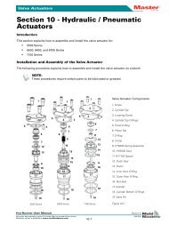
Each controller card has three main components:<br />
• Thermocouple amplifier,<br />
• CPU,<br />
• Multi-voltage output triac.<br />
• Soft start and continuously monitoring Ground fault.<br />
Thermocouple Amplifiers<br />
The thermocouple amplifiers have preset responses for both J and K type<br />
thermo couples. The selection of Sensor type on the Setup Page sets a<br />
flag that is read by the control card; this in turn sets the differential<br />
amplifier to match the selected thermocouple type.<br />
Central Processor Unit (CPU)<br />
The CPU provides the following facilities:<br />
• Closed and open loop control of the zones,<br />
• Communicates settings and thermocouple readings over the data link<br />
to the display micro-processor<br />
• Checks for alarm conditions, including blown output fuse(s),<br />
incorrect thermocouple wiring, zone over temperature condition,<br />
heater not responding to controller output and generates alarm<br />
information for the display screen and alarm relay (if fitted),<br />
• Controls the output power to both the on-board triacs using a number<br />
of self-tuning algorithms,<br />
Revision 1.4 <strong>Mold</strong>-<strong>Masters</strong> ® Page 9
The Controller Cabinet <strong>MZ</strong>-G/<strong>MG</strong> Manual<br />
Page 10<br />
• Controls a row of diagnostic LED’s mounted on the edge of the<br />
controller cards<br />
• Monitors the thermocouple every 20 milliseconds<br />
Phase angle firing is normally used for power control wherever probes<br />
require a fast or ultra-fast response. Burst firing is reserved for heavier<br />
loads such as manifolds or sprues where a medium or slow response may<br />
be used.<br />
The card requires no analogue calibration and is ready for use once set<br />
up from the display console.<br />
Output Triacs<br />
Each card is fitted with one output triac for each zone that is mounted onto a<br />
communal heat sink. This means that although the triacs have similar current<br />
handling capacities, their load management is also affected by their equivalent<br />
portion of the cooling surface.<br />
Power Supply Units (PSUs)<br />
The D.C. power supplies for the cards, data communications and an alarm<br />
output relay are all provided by a single Power Supply Unit. This is located<br />
behind the power-disconnecting panel.<br />
<strong>Mold</strong>-<strong>Masters</strong> ®<br />
Revision 1.4
<strong>MZ</strong>-G/<strong>MG</strong> Manual The Touch Screen Console<br />
The Touch Screen Console - (An introductory tour)<br />
This part of the manual introduces you, briefly, to the Touch screen<br />
console to show what facilities and what information is available.<br />
Display console for <strong>MZ</strong> G-series is a 10.4inch,<br />
800 by 600 pixel and 256-colour screen. It is<br />
capable to control up to 240zones. Mounted<br />
directly in front of the screen is a touch<br />
sensitive transparent panel used by the user to<br />
communicate with the system.<br />
The console housing contains all components<br />
necessary to generate displays and information<br />
for the control cabinet and includes a 3.5inch<br />
hard disk and 3.5inch floppy disk drive.<br />
Ethernet connections are also provided.<br />
The <strong>MZ</strong>-<strong>MG</strong> console can control up to 60zones, it buttons and indicators are<br />
as follows:<br />
1. Power Button (slide up and release) to turn the Console On and Off. Note<br />
that the console has its own internal batteries and it can run without the<br />
main-source supply. However, the rechargeable batteries will slowly run<br />
down until the main power is turned on and they can re-charge.<br />
If the power to the console is turned off or disconnected, and the console<br />
is left switched on, then the software will, after 5 minutes, save the run<br />
settings and then shut down the console. If the main controller is in Run<br />
mode then the control cards will maintain their temperature control at the<br />
last set point.<br />
2. Amber LED - blinks when the internal battery is charging. The LED is off<br />
when the battery is fully charged and blinks rapidly if the level is low.<br />
3. Green LED - shows when the console is turned on.<br />
4. Yellow LED - does not light and has no function on this console.<br />
5. LCD Brightness Control - press the "+" and "-" buttons to alter the screen<br />
brightness.<br />
Revision 1.4 <strong>Mold</strong>-<strong>Masters</strong> ® Page 11
The Touch Screen Console <strong>MZ</strong>-G/<strong>MG</strong> Manual<br />
Page 12<br />
6. TFT LCD Display - this display gives a touch screen interface that can be<br />
activated either by fingertip or other blunt pointer. If the screen is not<br />
activated for a set period then it will switch off in order to extend screen<br />
life and conserve power.<br />
All man-machine interface activities take place at both display consoles. Here,<br />
you can set-up the various controller parameters, view data, obtain<br />
performance information and check the operating status of each control zone.<br />
From the various pages, software on both consoles allows you to:<br />
• Set individual or global settings of temperature or percentage power<br />
levels, to each zone.<br />
• Configure cycle synchronization, to define the delay and boost times,<br />
preheat and boost values for each zone.<br />
• Inspect the tool store, where you can save or retrieve, the settings for up to<br />
20 different tools, (optionally more).<br />
• Set high and low temperature limits for closed loop zone control.<br />
• View displays of actual temperature when in closed loop mode or<br />
percentage power when in open loop zone control.<br />
• Carry out diagnostic routines for fault finding.<br />
• Set limits for temperature and power levels to prevent excessive set points<br />
being entered.<br />
• Control the Password protection on all settings.<br />
• Print out any displays or data listings.<br />
• Control zone performance using graphical displays.<br />
• Make connections from the PC console to other devices.<br />
Software, tool settings and pictures can be saved or loaded onto the display<br />
console computer by a compact flash disk in <strong>MG</strong>-series and by a 3.5” floppy<br />
disk in G-series.<br />
<strong>Mold</strong>-<strong>Masters</strong> ®<br />
Revision 1.4
<strong>MZ</strong>-G/<strong>MG</strong> Manual The Touch Screen Console<br />
Screen Layout<br />
There are eight separate pages that are used to display information and<br />
accept commands. Common to them all, are the top, right and bottom<br />
sidebars.<br />
To move between the pages, there are a series of TABS, displayed at the<br />
top of the page, that contain the page or function name. To Open a page,<br />
or function, simply touch the tab using either your fingers or a blunt<br />
pointer.<br />
On the right hand edge of each page is a command button bar. The bar<br />
contents change between pages, and buttons with the same appearance<br />
and titles that perform similar functions on different pages.<br />
At the bottom of every page there is a status line, which indicates the<br />
current Working Mode and the Alarm Status of the controller.<br />
Between the two is a Message bar that will be used to display other<br />
relative information such as:<br />
• Picture-to-Tool links<br />
• EasyView displays.<br />
• TimeLine Graph information<br />
Mode and Status Windows<br />
The Mode window flashes whenever the system is in an abnormal state<br />
such as Stopped, Standby, Startup, Shutdown, Boost or Testing. Only<br />
Run Mode shows as continuous.<br />
The Status window shows whether the system is a Normal healthy<br />
condition. Alternatively, it shows a Warning, or Alarm Status.<br />
Revision 1.4 <strong>Mold</strong>-<strong>Masters</strong> ® Page 13
The Touch Screen Console <strong>MZ</strong>-G/<strong>MG</strong> Manual<br />
Page 14<br />
The Eight Main Pages<br />
1) The Display page<br />
The Display page shows 40 zones at a time. If you have more than 40<br />
zones then you can use the Page Up and Down to move the display to<br />
further zones.<br />
The control buttons alongside can change according to your immediate<br />
needs. While the page is idle (no zone selected), you can use the top<br />
three buttons at the sidebar to select the operating mode of the controller.<br />
You can also use the fourth button, “Display” to alter the number of<br />
zones seen on the Display page. If you touch any zone, the control<br />
buttons then change to “Set”, “Zoom”, “Range”, and “Cancel”.<br />
Zone Status Indication<br />
At full size (40-Zone Display), each zone is displayed as a full controlpanel<br />
that carries five pieces of information:<br />
As well as showing temperatures and power levels the "Actual zone<br />
temperature" window changes colour to show normal and alarm states:<br />
• Green lettering on a black background – Normal status.<br />
• Black lettering on a yellow background – Temperature exceeds<br />
warning limits.<br />
• White lettering on a red background – Fatal error or temperature<br />
exceeds alarm limits.<br />
<strong>Mold</strong>-<strong>Masters</strong> ®<br />
Revision 1.4
<strong>MZ</strong>-G/<strong>MG</strong> Manual The Touch Screen Console<br />
Alternative Display Layouts<br />
If you want to see more than 40 zones at a time then the Display page<br />
can be modified to show more zones with less information. The sixth<br />
Function button has a dual function and , while no zone is selected (no<br />
blue highlight showing), touching the [Display] button will cause the<br />
Display page to cycle through 40, 70, 110, and 160 zones display in <strong>MZ</strong><br />
G-series as shown below. However, <strong>MZ</strong> <strong>MG</strong>-series can toggle between<br />
40 and 60 zones display only.<br />
70 zones – each zone shows Title, Actual and Set.<br />
110 zones – each zone shows Title and Actual<br />
160 zones – each zone shows Temperature<br />
Revision 1.4 <strong>Mold</strong>-<strong>Masters</strong> ® Page 15
The Touch Screen Console <strong>MZ</strong>-G/<strong>MG</strong> Manual<br />
Page 16<br />
Alternative Display Layouts – Zone Grouping<br />
Where a controller is used for a multi-part tool it may be more<br />
convenient to show the display page with zones grouped as in the tool.<br />
To show this option here are some fictitious screens shots from a twocolour<br />
32+32 zone tool. This would normally show the first 40 zones (all<br />
of colour 1 and some of colour 2) on the first page as shown below.<br />
Scrolling down would show the rest of colour 2 on the second page.<br />
Page 1 – both colours Page 2 – rest of second colour<br />
By using the “Zone Grouping” feature, that is described on page 47, the<br />
new display would be as shown below.<br />
Group 1 – First colour (Blue) Group 2 – First colour (Yellow)<br />
Note that this display option cannot be switched between Grouped and<br />
Ungrouped on the Display page. Once it has been configured on the<br />
Setup Page then it remains as the preferred display option. However, the<br />
“Display” button on the Display page still functions in its own right and<br />
so the number of zones, and the amount of displayed information, still<br />
alters to accommodate more zones on each touch of the button.<br />
<strong>Mold</strong>-<strong>Masters</strong> ®<br />
Revision 1.4
<strong>MZ</strong>-G/<strong>MG</strong> Manual The Touch Screen Console<br />
2) The EasyView page<br />
The EasyView page uses a picture of the moulding tool that has been<br />
integrated with miniature control panels or "mini-panels". Each minipanel<br />
can display a reduced version of a "Display-page" panel and will<br />
show either the Set or Actual temperature, the Applied-Power or<br />
Temperature-Deviation. Furthermore, this page may be used to both<br />
monitor the mould temperatures and also control them in a similar way to<br />
the previous display page.<br />
The control buttons alongside can change according to your immediate<br />
needs. While the page is idle (no zone selected), you can use the top four<br />
buttons to show “Set”, “Actual”, “Applied Power” or “Deviation” within<br />
the Mini-panels. If you touch any zone, in readiness to change values,<br />
then the control buttons then change to “Set” and “Zoom”.<br />
The main advantage of this page, against the Display page, is that<br />
temperatures here can be seen in relation to their position on the tool<br />
rather than being shown as a simple table.<br />
3) The Graph page<br />
The Graph page shows temperature versus time graphs for up to twenty<br />
zones at a time. (These can be selected in the prior Display page.)<br />
Revision 1.4 <strong>Mold</strong>-<strong>Masters</strong> ® Page 17
The Touch Screen Console <strong>MZ</strong>-G/<strong>MG</strong> Manual<br />
Page 18<br />
4) The ToolStore page<br />
ToolStore is a tool bank in which you can store up to 20 tool<br />
configurations. It also enables you to backup tool settings to a floppy<br />
disk and restore them to the controller, whenever they are needed again.<br />
The status of the displayed tool configuration is colour coded to indicate:<br />
Black the tool bank has a name but holds no data.<br />
Blue there are settings saved in this tool bank.<br />
Purple a tool that is currently being used with saved data.<br />
Red this indicates a tool that is currently being used but whose data<br />
has been modified and so, is different to that held in the tool<br />
bank.<br />
5) The Pictures page<br />
Your Touch screen controller can save, and display, up to 20 drawings or<br />
pictures that may be useful for operators. The same page is also used to<br />
configure mini-panels into EasyView pages.<br />
<strong>Mold</strong>-<strong>Masters</strong> ®<br />
Revision 1.4
<strong>MZ</strong>-G/<strong>MG</strong> Manual The Touch Screen Console<br />
6) The Utilities page<br />
The Utilities page contains several sub pages that contain run options,<br />
system configuration, printer details and past records.<br />
The selections within this page are:<br />
System To change the passwords and the system clock<br />
Printer To select a driver for your printer<br />
Event Log to observe what changes have been made to the<br />
controller configuration and when they were done.<br />
Trace Event To find changes that have been made to the controller<br />
settings<br />
Network To set up the Controller to communicate over a<br />
network.<br />
7) The Testing page<br />
This section allows you to carry out a series of defined tests to check<br />
zone interactions, heater wiring and thermocouple integrity.<br />
Revision 1.4 <strong>Mold</strong>-<strong>Masters</strong> ® Page 19
The Touch Screen Console <strong>MZ</strong>-G/<strong>MG</strong> Manual<br />
Page 20<br />
8) The Set-up page<br />
The Set-up page is concerned, mainly, with setting up your system: it<br />
also displays much useful information.<br />
By using the two slider-bars at the right and at the bottom you can see<br />
information and parameters for all the cards within your controller.<br />
The same grid that displays this information is also used to set-up the<br />
cards and some of the Console and Tool parameters. Operating<br />
parameters such as Set and Actual temperature are displayed here but<br />
cannot be configured on this page.<br />
The extreme left-hand column shows different icons that indicate all the<br />
control cards that the unit has detected.<br />
Here are the icons of different controller cards:<br />
4-zone card at 15Amps rating<br />
2-zone card at 30Amps rating<br />
4-channel digital Input/Output card for emote signalling<br />
<strong>Mold</strong>-<strong>Masters</strong> ®<br />
Revision 1.4
<strong>MZ</strong>-G/<strong>MG</strong> Manual Keyboard Entry<br />
Keyboard Entry<br />
The Controller automatically displays the keyboard whenever it needs an<br />
alphabetic entry such as Passwords or Tool names.<br />
It is a standard “qwerty” layout with touch-activated keys. Touching the<br />
keys enters the particular character into the display line: the [back space]<br />
button deletes them, starting from the last entry.<br />
To use the Shift key you may:<br />
touch it once – which initialises the next letter and then return to<br />
lower case, such as in “Names”<br />
touch it twice – which causes it to “LOCK-ON TO UPPER CASE”<br />
touch it once more to reset all letters to continuous lower case<br />
When you have finished typing then touch either:<br />
[Enter] to enter your typed text, or<br />
[Esc] to leave the keyboard with saving or entering text<br />
Revision 1.4 <strong>Mold</strong>-<strong>Masters</strong> ® Page 21
Keypad Entry <strong>MZ</strong>-G/<strong>MG</strong> Manual<br />
Keypad Entry<br />
Page 22<br />
The Controller automatically displays the keypad whenever it needs a<br />
numeric input. The keypad may be shown in two basic forms, which<br />
may, or may not, include the “Value” and “Mode” sections according to<br />
the required input.<br />
Numeric Input<br />
The Numeric keypad is offered whenever the<br />
system needs figures only, such as configuring<br />
the number of zones during Set-up.<br />
It has the numerical touch pads that allow you to<br />
input numbers and a display line at the top to<br />
show your input. There are also three function<br />
buttons:<br />
Delete - removes the last number typed in<br />
Enter - inputs the displayed figures into the<br />
controller<br />
Esc - closes the keypad and does not enter any<br />
input to the controller.<br />
Value and Mode Input<br />
Two further rows of buttons are the “Value” and<br />
“Mode” buttons. This version of the keypad is<br />
displayed wherever the controller may require<br />
more information such as controlling zones on<br />
the “Display” page.<br />
Value Input<br />
The three buttons on the “Value” row are:<br />
Set – enters the value to be a set point<br />
Add – adds the value that you enter to the<br />
existing set point.<br />
Subtract – subtracts the value that you enter<br />
from the existing set point<br />
<strong>Mold</strong>-<strong>Masters</strong> ®<br />
Revision 1.4
<strong>MZ</strong>-G/<strong>MG</strong> Manual Keypad Entry<br />
Mode Input<br />
The “operating” mode of any zone can also be set from the keypad. The<br />
three buttons are:<br />
Auto – this is the default mode for the controller, i.e. closed loop, where<br />
the controller output is determined as a set temperature and which<br />
relies on feedback from the thermal sensor. In this mode inputs are (as<br />
shown in the prompt) entered in degrees temperature.<br />
Manual – this is an optional mode, i.e. open loop where the controller<br />
output is fixed at a set power level, which is determined by you the<br />
operator. In this mode, input shall be a percentage power level.<br />
Slave – this is a “fallback” mode, which can be successfully used if a<br />
thermal sensor has failed. Rather than switching to manual, you have<br />
the option to slave the faulty zone to a working one. The temperature<br />
on the faulty zone then mimics the good zone that is working in auto<br />
(or closed loop).<br />
Provided the Value box is at “Set”, the prompt asks for the identity of a<br />
target zone, which should be operating at a similar temperature.<br />
Note: you cannot nominate another zone that is already slaved to<br />
another.<br />
Revision 1.4 <strong>Mold</strong>-<strong>Masters</strong> ® Page 23
Transferable Media <strong>MZ</strong>-G/<strong>MG</strong> Manual<br />
Transferable Media<br />
<strong>MZ</strong>-G and <strong>MG</strong> use different drive to access or store information onto a<br />
disk.<br />
Page 24<br />
DISPLAY CONSOLE ACCESS MEDIA TYPE<br />
<strong>MZ</strong> <strong>MG</strong>-Series<br />
<strong>MZ</strong> G-Series<br />
• Use Flash Card via a<br />
PCMCIA adapter<br />
• The drive is accessed<br />
through an opening at<br />
the top of the case.<br />
• Uses 3½ “ floppy disk<br />
• The drive is open and<br />
visible at the left hand<br />
side of the case when<br />
viewed from the front.<br />
<strong>Mold</strong>-<strong>Masters</strong> ®<br />
Revision 1.4
<strong>MZ</strong>-G/<strong>MG</strong> Manual<br />
How the <strong>MZ</strong> G/<strong>MG</strong> – Series<br />
Controller Works<br />
How the <strong>MZ</strong> G/<strong>MG</strong> – Series Controller Works<br />
This controller is designed to perform in closed and open loop<br />
configurations. However, we consider that the normal operating mode is<br />
closed loop.<br />
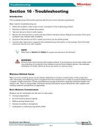
Whenever the controller is set to start, the system goes into a selfcalibration<br />
routine. This is illustrated in the following diagram and<br />
explained below.<br />
Temperature<br />
Set Point<br />
Soft<br />
Start<br />
1<br />
Load<br />
Test<br />
2<br />
1. The zone controller slowly ramps up the heater power and<br />
simultaneously looks for a positive temperature change at the<br />
thermocouple input. The controller verifies the actual rate of rise against<br />
a predetermined value. Power is slowly increased until the correct rate of<br />
rise is achieved.<br />
2. The controller now increases the zone temperature at a constant rate of rise<br />
until the temperature reaches about 110°C (230°F).<br />
3. At 110°C the controller performs a 'Load Test' on the zone heater to<br />
check its thermal characteristics. The output power is reduced to zero for<br />
a test period and the temperature monitored for a response. From all this<br />
information, the controller has built a mathematical model of the heater<br />
characteristics and so it can automatically select a Fast, Medium or Slow<br />
response-heating program that suits the tool. This allows more efficient<br />
control of the zones.<br />
4. The controller continues to ramp up the temperature to the set point,<br />
which should be achieved with minimum over-shoot.<br />
5. Having built a virtual model to map the tool and heater characteristics,<br />
the controller can maintain the temperature at an accurate point with<br />
virtually no deviation.<br />
Revision 1.4 <strong>Mold</strong>-<strong>Masters</strong> ® Page 25<br />
3<br />
4<br />
Load Test Delay<br />
Time<br />
5
How the <strong>MZ</strong> G/<strong>MG</strong> – Series<br />
Controller Works<br />
Page 26<br />
<strong>Mold</strong>-<strong>Masters</strong> ®<br />
<strong>MZ</strong>-G/<strong>MG</strong> Manual<br />
How the Console and Controller work together<br />
Because each individual card has its own central processor then, once it<br />
has received a signal to start and ‘knows’ its set temperature, it can<br />
function independently and hold the zone temperature until it is switched<br />
off. This means that once you have switched the system on, and it has<br />
reached a steady state, the console could be removed without affecting<br />
the cabinet. However, without the console, you have no means of<br />
monitoring the system, changing any set temperatures or shutting down<br />
in a controlled fashion.<br />
This generally means that if an accident, or major fault, causes the<br />
console to fail, the controllers in the cabinet can, if necessary, maintain<br />
production until an alternative console could be provided.<br />
If you should need to remove and/or reconnect your console during<br />
production then refer to page 97 for advice.<br />
Watchdog feature<br />
The Controller card CPU has a 'watchdog' timer that has to be reset by<br />
the system every 3 milli-seconds. If for any reason the software fails to<br />
reset the timer, the program is reset to the start position, which initialises<br />
the controller so protecting the tool against over-heating. The card<br />
resumes control of the zone from the start position.<br />
Revision 1.4
Setting up your controller<br />
What is covered in this section<br />
Page 28<br />
<strong>Mold</strong>-<strong>Masters</strong> ®<br />
<strong>MZ</strong> G/<strong>MG</strong>-Series Manual<br />
Setting up your controller<br />
New <strong>MZ</strong> GUS Touch Screen controllers are correctly configured at the<br />
factory and you should not need this section for a new system. However,<br />
if you are reconfiguring your Touch Screen console to a new tool or<br />
environment, then you may well need this chapter of the manual.<br />
Your first consideration must be the general controller parameters such<br />
as passwords and temperature scales. These allow you to configure your<br />
controller to work to your preferences.<br />
After you have completed the general settings you can go on and set it up<br />
to control its first tool. This necessitates setting up zones, sensors,<br />
temperatures, boost settings and alarms.<br />
Finally, we look at saving your first tool settings, so they can be used<br />
again in the future.<br />
What is covered in this section<br />
Setting passwords & password active timer<br />
Setting display time (blanking delay)<br />
Setting communications speed<br />
Setting the system time<br />
Connecting to a printer<br />
Setting Network Connections<br />
Configuring the controller to your tool<br />
Setting zone types<br />
What sensors are you using?<br />
Setting the required temperatures<br />
Setting boost values<br />
Setting alarms and limits<br />
Setting up EasyView Page<br />
Revision 1.4
<strong>MZ</strong> G/<strong>MG</strong>-Series Manual<br />
Setting up your controller<br />
Controlled access though passwords<br />
Controlled access though passwords<br />
When you first use your touch screen controller you find, as you go through<br />
some pages, that some functions are protected by password access. There are<br />
two levels of password access control that are:<br />
User – gives low-level access to:<br />
• switch the tool on and off,<br />
• alter temperatures,<br />
• select different tools<br />
System – gives high-level access to:<br />
• all user-level functions,<br />
• set the user password,<br />
• re-configure the settings for a<br />
new tool,<br />
• store and load new tool<br />
settings to/from the disc<br />
Every machine leaves our factory<br />
with two levels of password protection. We recommend that you change these<br />
as soon as possible to establish your own security.<br />
Factory Set Passwords<br />
Each data entry box is protected by a User or System level password. The<br />
User level password, "UNIX" and System level password "LINUX" are both<br />
set at the factory and may be changed by the user at any time. Each time a<br />
password is entered it is valid for the time period set in the Utilities page.<br />
Note: It is recommended that after completing any work in a password<br />
guarded page that you exit that page immediately to prevent unauthorised<br />
entry.<br />
Changing Passwords<br />
It is recommended that the factory set passwords be changed at the earliest<br />
opportunity. To change the passwords follow the steps below:<br />
System Password<br />
1. Open the “Utilities” page.<br />
2. Enter the password area by opening the System tab.<br />
3. In the System box touch [Edit] to display the Keyboard entry<br />
window.<br />
4. First establish your authority by entering the current System password.<br />
5. Next, enter your new preferred System password.<br />
6. Finally, re-enter your new System password to confirm it.<br />
Revision 1.4 <strong>Mold</strong>-<strong>Masters</strong> ® Page 29
Setting up your controller<br />
Setting your password timer<br />
Page 30<br />
<strong>Mold</strong>-<strong>Masters</strong> ®<br />
<strong>MZ</strong> G/<strong>MG</strong>-Series Manual<br />
User Password<br />
1. Open the “Utilities” page.<br />
2. Enter the password area by opening the System tab.<br />
3. In the [User] box touch Edit to display the Keyboard entry window.<br />
4. First establish your authority by entering the System password.<br />
5. Next enter you new preferred User password.<br />
6. Finally re-enter the new User password to confirm it.<br />
Setting your password timer<br />
The password timer function is used to disable System access. Once the<br />
system password has been used to set up a zone, then the pages<br />
remain open to access until either:<br />
• Go back to a different page such as “Display”<br />
• Password timer times out.<br />
Until either of these events occurs, then the pages remain open to further<br />
changes. Should you, as a system administrator, be called away while<br />
setting up the controller then it is reassuring to know that, after a set<br />
time, unauthorised access is not available.<br />
1. Open the “Utilities” page.<br />
2. Enter the password area by opening the<br />
“System” tab.<br />
3. In the “Time Limit” box touch EDIT to<br />
display the Keyboard entry window.<br />
4. First establish your authority by entering the<br />
System password.<br />
5. At the Password Timer keyboard enter your<br />
preferred elapsed time in minutes and touch<br />
Enter.<br />
Password Override<br />
To override the User and System Password control, set the Password Timer to<br />
"99". This setting negates the need to enter a Password at any of the usual<br />
checkpoints such as "Load Tool" or "Temperature Change". Under this<br />
condition, the only function that still needs a Password input is the "Change<br />
Password" action.<br />
Revision 1.4
<strong>MZ</strong> G/<strong>MG</strong>-Series Manual<br />
Setting up your controller<br />
Changing The Display Time (Blanking<br />
Delay)<br />
Changing The Display Time (Blanking Delay)<br />
In order to preserve energy, the screen saver blanks the monitor screen after it<br />
has been idle for a preset time. You can set this preset time so that the screen<br />
stays visible for more or less time by using the<br />
"Screen Blanking Delay" option on the<br />
Utilities> System page.<br />
1. Open the "Utilities" page.<br />
2. Enter the Set time area by touching the<br />
"System" tab.<br />
3. Touch the box containing a time element that you wish to change.<br />
4. Within the Screen Blanking Delay, touch the [Edit] button to display a<br />
keypad.<br />
5. Enter the time (in minutes) for idle screens remain displayed.<br />
6. Select [OK] to save the new setting to the system.<br />
Setting the Communication Speed<br />
Normally new Touch Screen consoles are supplied with new Cabinets in<br />
which case there is no problem with communication between the two.<br />
However, if you are using a new console with an older cabinet there may<br />
be a mismatch between their communication speed. This arises because<br />
newer consoles and cabinets communicate at a higher speed than older<br />
models.<br />
How to change the Baud Rate<br />
1. Open the "Utilities" page.<br />
2. Touch the "System" tab to find the<br />
Communication Switch<br />
3. Check to see that the Baud rate is "High"<br />
4. Within the "Communication Speed" box touch [Edit]<br />
5. If requested, type in the System Password.<br />
6. The system will now switch to "Low", the communications will be reset<br />
and the "Scan" LEDS should flash sequentially.<br />
How to check the Communications<br />
To check that the console and cabinet are communicating, observe the<br />
"Scan" LEDs on the control cards. In a normal condition, you can see the<br />
"Scan" LEDs flashing sequentially through the cards - this shows that the<br />
console can talk to the control cards. If no "Scan" LEDS light up then the<br />
communication has failed. Check first that the data lead is correctly fitted<br />
and, if all seems normal, then change the "Baud" rate to "Low" as shown<br />
below.<br />
You may observe an in-between situation where some of the "Scan"<br />
LEDS light up while others do not. This may happen if some of the cards<br />
in the older cabinet have, at some time in the past, been changed for<br />
newer ones. In this case the few newer cards will communicate at the<br />
higher speed (and light their "Scan" LEDs) while the older original cards<br />
will remain unlit.<br />
Revision 1.4 <strong>Mold</strong>-<strong>Masters</strong> ® Page 31
Setting up your controller<br />
Setting the System Time<br />
Page 32<br />
Setting the System Time<br />
It is recommended that you set the correct<br />
time and time zone so that you may take<br />
full advantage of the software features that<br />
use the time function.<br />
<strong>Mold</strong>-<strong>Masters</strong> ®<br />
<strong>MZ</strong> G/<strong>MG</strong>-Series Manual<br />
1. Open the “Utilities” page.<br />
2. Enter the Set time area by touching the<br />
“System” tab.<br />
3. Touch the box containing a time<br />
element that you wish to change.<br />
4. Use [▲] and [▼] buttons to set the required value.<br />
5. Select [OK] to save the new setting to the system.<br />
Configuring your controller to a printer<br />
Before you can obtain a hard copy of any records or details, you must<br />
first match the controller to your printer.<br />
1. Open the “Utilities” Page<br />
2. Touch the “Print” Tab.<br />
3. Use the Printers list and scroll bar to<br />
find a suitable printer. There may not be<br />
a precise match for your own printer;<br />
but there are a few generic descriptions<br />
such as “DeskJet” and “Laser” that<br />
should provide a satisfactory printer<br />
link.<br />
(A brief description of the printers catered<br />
for by that selection is displayed in the<br />
adjacent window).<br />
4. Select the paper size.<br />
5. Having made your choice, touch the [Accept] button to accept the settings<br />
or [Cancel] to leave the page.<br />
6. If you need to confirm the printer connection then check that the printer is<br />
correctly connected (see Appendix A for details) and try printing out a<br />
picture such as Display or Graph page.<br />
Should you have any difficulties then contact <strong>Mold</strong>-<strong>Masters</strong> ® for further<br />
assistance.<br />
OPERATION NOTE: if need to cancel a print queue then touch the [Clear<br />
Print Queue] button on this page. It cancels any print requests that are in the<br />
current queue.<br />
Revision 1.4
<strong>MZ</strong> G/<strong>MG</strong>-Series Manual<br />
Setting up your controller<br />
Configuring your controller to a printer<br />
Setting up Network Connections<br />
Touch Screen consoles can communicate over an Ethernet network in order to<br />
pass information both to and from the console. You can set up your network<br />
connection with the Utilities section by touching the [Network] page.<br />
What Facilities Network offers<br />
Provided your remote terminal has an X-Win server, you can easily<br />
communicate with the Console to return an emulation of the working<br />
program. This means that you can monitor the Touch Screen Console and you<br />
also have the facility for remote control. If you have network connections to<br />
multiple consoles then you can transfer files such as tool settings and picture<br />
files between the different machines.<br />
How to make the connection<br />
In order to use this facility, connect your console to an active network using a<br />
T-base lead to the appropriate socket on the Touch Screen computer.<br />
The next step is to allocate a unique name to the machine within your factory<br />
environment and set the appropriate domain name for your own system.<br />
Obtaining an IP address depends on the size of your internal network. For<br />
connection to a large network it may be sufficient to enable the Automatic IP<br />
facility. On a smaller network you may need to disable the automatic facility<br />
and use the [Edit] buttons to enter your preferred IP address and Sub-net mask<br />
details.<br />
Networking configuration depends a lot the your system and should only be<br />
carried out by competent IT staff. Should you need further information please<br />
contact <strong>Mold</strong>-<strong>Masters</strong>®.<br />
Revision 1.4 <strong>Mold</strong>-<strong>Masters</strong> ® Page 33
Setting up your controller<br />
Configuring your controller to a tool<br />
Page 34<br />
<strong>Mold</strong>-<strong>Masters</strong> ®<br />
<strong>MZ</strong> G/<strong>MG</strong>-Series Manual<br />
Configuring your controller to a tool<br />
<strong>MZ</strong> controllers are correctly configured at the factory. However, if you<br />
are reconfiguring your Touch Screen Console to a new tool or<br />
environment then you may need to establish new settings on the Setup<br />
Page.<br />
There are six main stages in setting up the new tool, which are:<br />
Stage 1<br />
- Prepare a new tool bank slot ready to accept the first<br />
configuration.<br />
Stage 2<br />
- Configure the controller to establish number of zones, limits, Hi<br />
and Lo alarms, and what warnings you require.<br />
Stage 3<br />
- Configure the individual zones, or groups of zones, to match the<br />
probes, manifolds and any other special feature of your moulding<br />
tool.<br />
Stage 4<br />
- Set the particular zone temperatures for the tool.<br />
Stage 5<br />
- Finally, save all your settings into the new tool bank slot that you<br />
created in stage 1.<br />
Stage 6<br />
- Import the relative tool images and use the "Pictures" page to<br />
implant them with Mini-panels.<br />
Revision 1.4
<strong>MZ</strong> G/<strong>MG</strong>-Series Manual<br />
Stage 1 – Creating a new tool slot<br />
Setting up your controller<br />
Creating a new tool slot<br />
The first step in configuration is to create a named tool slot. If you omit<br />
this stage and proceed to configure your tool then all your settings<br />
created in Stages 2-4 may be lost if you do not have a named slot ready<br />
to accept them.<br />
1. Touch the “ToolStore” tab to open the page.<br />
2. Select a blank sub-tab and touch [New].<br />
3. Enter your System password to gain access.<br />
4. Type in a new name for the proposed tool. When you type in the new<br />
name, note that Shift capitalises first letters and a backspace steps<br />
back and deletes last entries. When you have finished, press [Enter]<br />
and the Configure Controller menu, shown on the following page,<br />
appears.<br />
5. Keep the Configure menu open and turn to<br />
“Stage 2 – Configuring overall Settings”.<br />
Revision 1.4 <strong>Mold</strong>-<strong>Masters</strong> ® Page 35
Setting up your controller<br />
Configuring overall settings<br />
Page 36<br />
Stage 2 - Configuring overall settings<br />
<strong>Mold</strong>-<strong>Masters</strong> ®<br />
<strong>MZ</strong> G/<strong>MG</strong>-Series Manual<br />
After touching [Config] on the Setup Page or “New Tool” on the<br />
ToolStore page the following panel presents itself. This contains a<br />
number of options for the systems that you need to configure for the<br />
console to run correctly. The options are listed here and each is<br />
described in the following pages.<br />
You can use the scroll bar in the centre to browse the list and, as each<br />
option is selected, a brief description appears in the panel alongside.<br />
Below the panel will be an edit function for inputting numerical data or a<br />
pair of touch switches that you can use to toggle the required option.<br />
Touching [OK] at the bottom of the panel accepts your input selection,<br />
alternatively, touch [Cancel] to leave this screen without changing any<br />
existing settings. The only exception is the “Auto Detect” which will run<br />
as soon as you touch [Yes].<br />
System Options include:<br />
AutoDetect<br />
Alarm Time<br />
Allow ToolLoad<br />
AutoStop Time<br />
Blanking Delay<br />
Baud Rate<br />
BoostTime<br />
Connection<br />
Display Mode<br />
Input Signal<br />
Language<br />
Master Only<br />
Power Mode<br />
Startup Mode<br />
Standby Delay<br />
Shutdown Timer<br />
Temp Scale<br />
Revision 1.4
<strong>MZ</strong> G/<strong>MG</strong>-Series Manual<br />
Setting up your controller<br />
Configuring overall settings<br />
For an overview of all these parameters, and how they are currently set,<br />
touch [View]; the following screen appears.<br />
Auto Detect<br />
Touch [Yes] discards all the current settings and options and allows the<br />
controller to interrogate the cabinet to determine what cards are present<br />
within the rack(s). Following this automatic process, the “Setup” page<br />
displays the controller card information ready to configure the tool<br />
parameters.<br />
DO NOT touch [Yes] if the current settings are essential and have not yet<br />
been saved to a spare slot in the ToolStore.<br />
Normally, the console and the controller may be considered as a single<br />
unit. However, if the console is networked to a number of controllers,<br />
you should note which controller you are interrogating. To check this,<br />
scroll down to “Connection” to identify the controller with which the<br />
console is currently communicating.<br />
Alarm Time (seconds)<br />
This function allows you to configure a brief delay that is put between<br />
and alarm condition being detected and an external alarm being sent.<br />
This allows you to prevent fleeting deviations causing nuisance alarms or<br />
to compensate for slow reacting systems.<br />
Allow ToolLoad<br />
This facility allows you to control whether tools may be changed while<br />
the system is in “Run” mode or whether such a tool swap is disabled.<br />
How you use this option will depend on local circumstances and the<br />
following may be helpful… It may be that your ToolStore contains<br />
variations of the same basic tool, each with the same number of zones<br />
and all configured similarly except that there may be temperature<br />
variations between the different tools. If so then you may well want to<br />
swap tools on-the-fly as this gives you the ability to make present<br />
temperature changes to suit special conditions.<br />
Revision 1.4 <strong>Mold</strong>-<strong>Masters</strong> ® Page 37
Setting up your controller<br />
Configuring overall settings<br />
Page 38<br />
<strong>Mold</strong>-<strong>Masters</strong> ®<br />
<strong>MZ</strong> G/<strong>MG</strong>-Series Manual<br />
Alternatively, a console may have a collection of very different tools<br />
within the ToolStore because it may be physically moved from one<br />
controller to another and used on different presses. With different zones<br />
counts and operating conditions then it is more likely that you may not<br />
want to switching tools on-the-fly in “Run” mode.<br />
Finally, a console may be configured to several controllers via a local<br />
network in which each controller may have similar, or dissimilar, tools<br />
and settings. In this situation, the ToolStore [Load] button is the only<br />
way in which the console may be switched to communicate with<br />
different controllers. Consequently, an operator may need to select<br />
differenet tools while the current tool remains in “Run” mode and so, the<br />
console would have “Allow ToolLoad” set to “Enable”.<br />
Auto Stop Time<br />
This function is not yet supported and will only be supported on a<br />
console that has been supplied with the MODBUS protocol.<br />
This allows you to introduce a time delay (in seconds) from after the<br />
system stops receiving a remote “running” signal until the console<br />
initiates a STOP command.<br />
This function is only associated with a MODBUS interface and does not<br />
affect any remote input that may be received through the Input/Output<br />
card.<br />
Because this system initiates a STOP command when running signal has<br />
inadvertently been lost through a broken connection or similar.<br />
Blanking Delay<br />
In order to optimise screen life, the screen saver software blanks the<br />
monitor screen after the controller has been idle for a preset time. You<br />
can set this preset time so that the screen stays visible for more or less<br />
time by using the “Screen Blanking Delay” option.<br />
To set the Delay touch the [Edit] button and enter the time (in minutes)<br />
for idle screens remain displayed.<br />
Note: A time of “99” disables the screen blanking so that it remains<br />
always visible.<br />
Baud Rate<br />
Modern electronics enabled newer control cards to use a higher<br />
communications speed (or baud rate) to communicate with the console,<br />
although they are capable of working at low speed as well. Older cards,<br />
however, were only capable of communicating with the console at slow<br />
speed.<br />
Normally, new Touch Screen consoles are supplied with new controllers<br />
in which case there is no communication problem between the two.<br />
However, if you are using a new console with an older controller there<br />
may be a mismatch between their communication speed. If so then the<br />
lack of communication between the two can be rectified by selecting the<br />
lower Baud rate.<br />
Revision 1.4
<strong>MZ</strong> G/<strong>MG</strong>-Series Manual<br />
Setting up your controller<br />
Configuring overall settings<br />
How to check the communications<br />
To check that the console and controller are communicating, observe the<br />
“Scan” LEDs on the control cards. In a normal condition, you can see<br />
the “Scan” LEDs flashing sequentially through the cards – this shows<br />
that the console can talk to the control cards. If no “Scan” LEDs light up<br />
then the communication has failed. Check first that the data lead is<br />
correctly fitted and, if all seems normal, then change the “Baud” rate to<br />
“Low” as shown below.<br />
You may observe an in-between situation where some of the “Scan”<br />
LEDs light up while others do not. This may happen if some of the cards<br />
in the newer controller have, at some time in the past, been changed for<br />
older ones. In this case the few older cards will not communivate the<br />
higher speed (and not light their “Scan” LEDs) while the newer original<br />
cards will light.<br />
To Change the Baud Rate<br />
Select “Baud Rate” and select either “High” or “Low” to match your<br />
communication speed to the controller cards being used.<br />
Boost Time<br />
This option allows you to set how many seconds the heater temperature is<br />
boosted for, whenever it is selected. To set the boost time period, touch the<br />
“Edit” button to show the keypad and key in your required setting.<br />
Connection<br />
This option selects the mode of communication between the console and<br />
one or more cabinets that are connected to it.<br />
If the drop-down only offers ‘Serial Port’ then the console has a one-toone<br />
serial connection with the associated controller cabinet.<br />
If the associated cabinet is fitted with a Comms card, and it is connected<br />
to the console via a CAT5 cable from the 10Base-T output, then clicking<br />
on the “Default Controller Connection” drop-down will reveal a choice<br />
where serial Port and hrcnetxxx are both listed. If so then ‘hrcnet’ option<br />
could be chosen.<br />
If the console is connected to via a Local Area network (LAN) to more<br />
than one HRC cabinet then “Default Controller Connection” will show<br />
several hrcnetxxx options, each of which corresponds to a different HRC<br />
Cabinet. However, it may communicate with and control remote<br />
controllers over a Network system.<br />
Display Mode<br />
This option allows you to choose how the display page and set-up page<br />
group the zones. “Sorted mode separates all the zone types into a predetermined<br />
order, which is Spear zones first followed by Probes, then<br />
Manifolds, then Specials. “Mixed” mode groups the probe and manifold<br />
zones as they are positioned within the card rack, so that manifolds may<br />
appear out of sequence order, but grouped with their corresponding<br />
probe zones.<br />
Revision 1.4 <strong>Mold</strong>-<strong>Masters</strong> ® Page 39
Setting up your controller<br />
Configuring overall settings<br />
Page 40<br />
<strong>Mold</strong>-<strong>Masters</strong> ®<br />
<strong>MZ</strong> G/<strong>MG</strong>-Series Manual<br />
Input Signal<br />
Your console may have a remote input (normally open pair) that can be<br />
closed to switch the operation mode of the controller. Either of two<br />
options ay be selected which are: BOOST – this switches the controller<br />
into boost mode. While the remote contacts are closed the controller<br />
remains at the boost level and so disregards the pre-configured “Boost<br />
Time” period.<br />
STANDY – this switches the controller into Standby mode while the<br />
remote line is closed and returns to its previous state when the signal is<br />
removed.<br />
NOTE:<br />
• The remote input is only effective when the system is in “RUN”<br />
mode.<br />
• Only those zones that have Boost or Standby temperatures configured<br />
in their SetUp will respond to the remote input signal.<br />
Language<br />
You may select a preferred language for the screen and online help.<br />
To choose another language touch the “Down-arrow” next to the current<br />
language indication and choose another from the displayed options.<br />
Master Only<br />
This option is required for Valve-Gate moulds that need to hold back the<br />
nozzles and other zones until the designated Master zones have reached their<br />
full working temperature: using this Startup option helps to protect the Valve<br />
gates and seals when starting from cold. Once the Master zones are up to<br />
working temperature, the controller then switches to “Run” for all the other<br />
zones to heat up to their own normal operating temperature.<br />
Power Mode<br />
If you have control cards with current measuring coils fitted to your system<br />
then this option enables the main display page to show either Current or<br />
Percentage Power in the zone boxes on the Display page.<br />
Startup Mode<br />
This last option allows you to switch between two different starting modes<br />
which are:<br />
Master – which allows the console to use the previous “Master Only” setting.<br />
Stage – which enables the console to startup by heating allocated groups of<br />
zones in successive stages, allowing each group to reach their correct<br />
operating temperature between energizing the next group.<br />
Temp(erature) Scale<br />
The temperature window allows you to select an appropriate temperature<br />
scale. The input offers a choice between degrees Centigrade and degrees<br />
Fahrenheit.<br />
Revision 1.4
<strong>MZ</strong> G/<strong>MG</strong>-Series Manual<br />
Setting up your controller<br />
Setting up Zones Type<br />
Auto Manual Mode<br />
Auto Manual Mode is enabled for automatically for any zone when a<br />
thermocouple fails. The system refers to a Look-up table that holds historical<br />
power levels for the tool. The temperature control is automatically changed<br />
over to open loop control mode using the table data.<br />
Note: The preferred method to overcome thermocouple failure is to use the<br />
Slave command, (see page 61).<br />
Finished configuration?<br />
Once you have completed all the necessary configuration boxes, and want to<br />
save them as they have been set, touch the [OK] button.<br />
If you do not wish to accept the changes made, touch [Cancel]. The configure<br />
menu disappears, and the system reverts back to any previous selections that<br />
may have been made.<br />
On-screen Help is available by touching the [Help] button.<br />
Stage 3a - Setting up Zones Type<br />
After "Auto-Detect" has interrogated the controller, your console<br />
"knows" what cards are present. However you need to allocate functions<br />
to the various cards, for example, to establish which zones are probes (or<br />
nozzles) and which are manifolds. There are other parameters, such as<br />
Specials, that you need to set up and the following example will help to<br />
step you through this procedure.<br />
1. Select the zones by touching the white boxes in the "Type" column.<br />
Touch the boxes that are adjacent to the particular cards that you<br />
intend to configure. Touching one box selects that channel which<br />
then turns to blue. Touching the box again deselects the zone.<br />
(Unselecting is as simple as touching [Cancel] on the side bar or, if there<br />
are only a couple of zones, touching them a second time to de-select<br />
them.)<br />
Revision 1.4 <strong>Mold</strong>-<strong>Masters</strong> ® Page 41
Setting up your controller<br />
Setting Tool Parameters<br />
Page 42<br />
<strong>Mold</strong>-<strong>Masters</strong> ®<br />
<strong>MZ</strong> G/<strong>MG</strong>-Series Manual<br />
2. Touching more subsequent boxes adds them to the initial selection.<br />
Any configuration that is subsequently selected is applied to all the<br />
highlighted zones. Or, touching non-adjacent boxes and then the<br />
"Range" button on the right-hand side extends your selection to<br />
include all the zones in between the first two zones selected.<br />
3. With all the appropriate zones highlighted,<br />
touch [Set] to bring up the Configure Card<br />
Slot option and select the zone type.<br />
4. Touch [OK] to confirm the choice and you<br />
automatically return to the Setup page<br />
where you will see the card type setup<br />
along with their respective default values.<br />
5. Repeat the above steps to complete all the<br />
zone types.<br />
Stage 3b - Setting Tool Parameters<br />
Following an initial zone set up, many of the parameters are populated<br />
with Default Values.<br />
This stage shows how to make any changes<br />
to either the current or the initial default<br />
values:<br />
1. Select Zone(s)<br />
- In order to set up any tool parameters<br />
you first need to select the zones. The<br />
diagram here shows four such zones.<br />
2. Select the parameter<br />
- To select any one value, you may touch<br />
the appropriate column, at any point in<br />
the column, including the header. In<br />
this example the "Standby" values are<br />
to be set up, and touching the screen<br />
anywhere in the "Standby column"<br />
highlights the parameters against the<br />
selected zones.<br />
- Touching in another column deselects<br />
the first parameter and accepts the<br />
second selection.<br />
Revision 1.4
<strong>MZ</strong> G/<strong>MG</strong>-Series Manual<br />
Setting up your controller<br />
Setting Tool Parameters<br />
3. Set the Value<br />
- The next step is to program in the<br />
Standby value by touching "Set" on the<br />
right-hand side.<br />
If this is your first visit to the Setup<br />
procedure then you give the System<br />
password to establish your authority.<br />
Subsequent visits from the same screen<br />
do not require authorisation.<br />
After entering the password either a<br />
keypad or a related Setup box appears on the screen where you can<br />
now input your preferred values.<br />
Repeat steps 1 to 3 to complete all zone parameters.<br />
The following section lists all of the parameters that can be seen on the Setup<br />
page, and gives an explanation of each.<br />
Explanations on each Tool Parameters<br />
Rack Address<br />
This indicates where on the rack the particular card or zone is located.<br />
This reading does not refer to a physical position but is determined by a<br />
miniature logic-switch on the back-plane board.<br />
Alias<br />
If no Alias is given then the system shows zone types on the Display page<br />
with their inherent type name, i.e. Probe 1, 2, 3 etc or Manifold 1, 2 etc.<br />
However, setting up "Alias" enables it to show the zones with a more<br />
meaningful name. On a two color machine, for instance, it may be more useful<br />
to name one bank as "Red 1, 2, 3 etc." and the second bank as "Blue 1, 2, 3<br />
etc.". To use the Alias function select all the zones within a named group and<br />
touch the "Alias" column to show this box…<br />
Touch [Edit] to display the keyboard and key in a new name - you can remove<br />
any existing name by touching the [Back Space] key.<br />
Alias is an auto-numbering function so if you number the first zone in a group<br />
"Red 1", subsequent zones in the same selected group bear the following<br />
numbers i.e. "Red 2", "Red 3" etc…<br />
Revision 1.4 <strong>Mold</strong>-<strong>Masters</strong> ® Page 43
Setting up your controller<br />
Setting Tool Parameters<br />
Page 44<br />
<strong>Mold</strong>-<strong>Masters</strong> ®<br />
<strong>MZ</strong> G/<strong>MG</strong>-Series Manual<br />
Set<br />
This shows the zone's current "Set" temperature and is a Tool Operating<br />
parameter that cannot be configured on the Setup page - it is shown for<br />
reference only.<br />
Actual<br />
This shows the zone's "Actual" temperature and is displayed for reference only.<br />
Power<br />
This shows the zone's current power level. If the zone is in Manual then this is<br />
a Tool operating parameter that cannot be configured from the SetUp page - it<br />
is shown for reference only. If the zone is in Auto (closed-loop) then it is a<br />
display of the current level of power being delivered. As such it is still only<br />
displayed for reference.<br />
Standby<br />
A "Standby" command allows you to temporarily reduce the temperatures of<br />
selected zones until a "Run" command restores the zones to their normal<br />
operating temperature. The value entered here allows you to individually set<br />
that temperature depression on a zone-by-zone basis. This means that if you<br />
want a zone that normally runs at 280ºC, to reduce it to 250ºC during standby,<br />
then you must enter the difference temperature, which is 30ºC, at this point.<br />
Any zones are left at zero, will not respond to a standby request but stay at<br />
their normal operating temperature.<br />
Boost<br />
A "Boost" command allows you to temporarily raise the temperatures of<br />
selected zones for a set period. The value entered here allows you to<br />
individually set that temperature increase on a zone-by-zone basis. Any zones<br />
are left at zero, will not respond to a Boost request but stay at their normal<br />
operating temperature.<br />
Please note that, during a boost command, the "Boost Time" is the main<br />
determining factor. If, on a slow responding manifold, you set a high boost<br />
temperature while the boost time is set short, then the zone is unlikely to reach<br />
your set Boost temperature before the Boost Time limit expires.<br />
Master Zone<br />
Setting a "Master" zone for any group of zones is an option that must be left<br />
until all the zones have been initially configured. Once you have allocated the<br />
Probes and Manifolds, then you can select groups of dependent zones and use<br />
this option to set their master zone. Usually, you select a group of Probes in<br />
order to designate a common Manifold as a Master Zone. However, on larger<br />
tools you may also select a group of smaller, or sub, manifold zones to<br />
designate a larger main distribution Manifold as their Master zone. Both of<br />
these options are equally catered for using this option.<br />
Revision 1.4
Se t<br />
Tem perature<br />
Zero<br />
<strong>MZ</strong> G/<strong>MG</strong>-Series Manual<br />
Setting up your controller<br />
Setting Tool Parameters<br />
Warning and Alarm Levels<br />
These four columns set the first and second stage (Warning and Alarm) levels<br />
that monitor the zone temperatures. These generate visual warnings should the<br />
Actual temperatures deviate too far away from the nominal "Set" temperature.<br />
If no other values are chosen, these parameters are automatically set to ±5° C<br />
for Warning and ±25° C for Alarm levels. However all these may be reset to a<br />
preferred value by touching in the appropriate column and then setting new<br />
levels on the keypad.<br />
If any temperatures deviate by an amount that exceeds the first stage limits<br />
constitutes a warning. This displays a "Warning" message in the lower Status<br />
box and the offending zone has its Actual Temperature window changed to<br />
Black text against yellow background. If any temperature then deviates further<br />
and exceeds the second stage limits it raises the situation to Alarm. This<br />
occurrence displays an "Alarm" message in the lower Status box, changes the<br />
Actual temperature window to show White text against a Red background and<br />
actuates an Alarm relay that may be used to set of a Beacon, Siren of other<br />
remote device. These "Warning" and "Alarm" limits are a common feature on<br />
all zones, whether they control or monitor.<br />
Maximum Temperature Setting<br />
This column allow you to set the maximum temperature permitted for<br />
Automatic/Closed Loop working for any zone, or group of zones. This<br />
parameter may be set to inhibit any changes up to excessively high probe<br />
temperatures that may cause material degradation or tool damage.<br />
Maximum Power Setting<br />
This column allow you to set the maximum temperature permitted for<br />
Manual/Open Loop working for any zone, or group of zones. This parameter<br />
may be set to inhibit any changes up to excessively high probe temperatures<br />
that may cause material degradation or tool damage.<br />
TC Offset Value<br />
Some manufacturers make probes where the T/C sensor is closer to the<br />
rear band heater than the tip. For such a type, the displayed T/C<br />
temperature could be noticeably different to<br />
the temperature of the plastic material at the<br />
tip. In such a situation it helps if the operator<br />
Positive Offset can set some “offset” so that temperature on<br />
the Display page reflects the working<br />
temperature at the tip rather than the actual<br />
Negative Offset T/C temperature somewhere else within the<br />
probe. The T/C Offset Value allows you to<br />
achieve such temperature display<br />
compensation.<br />
While using a set Temperature of, say, 250ºC<br />
on the Display Page and then putting (plus)<br />
20 degrees into the T/C Offset column on the<br />
Am bient Setup Page, the zone will then control the<br />
temperature to 270ºC. However the Display<br />
Corrected Offset at low temperature<br />
ActUal Controlled Temperature<br />
DISPLAYED TEMPERATURE<br />
Actual Controlled Temperature<br />
Revision 1.4 <strong>Mold</strong>-<strong>Masters</strong> ® Page 45
Setting up your controller<br />
Setting Tool Parameters<br />
Page 46<br />
<strong>Mold</strong>-<strong>Masters</strong> ®<br />
<strong>MZ</strong> G/<strong>MG</strong>-Series Manual<br />
page will still show 250ºC. Also, the offset is a constant value, so that<br />
increasing the zone set temperature to 290ºC on Display Page means that<br />
the zone is then controlled to 310ºC at the T/C point. Using a minus T/C<br />
offset has the same effect only working in the opposite direction, i.e.<br />
with Set Temperature at 250ºC and T/C Offset at minus 30ºC the actual<br />
controlled temperature at the T/C is 220ºC.<br />
However the application of T/C Offset is proportional. This means that if<br />
you apply plus 20º offset to a zone whose set temp is normally 250º,<br />
while the tool is at its ambient temperature of 21º, then you will not see<br />
the display temperature immediately corrected by 20º to show 1º. What<br />
happens is that the controller uses only a proportion of the offset while<br />
the tool is below its set temperature. The graph on the left shows how a<br />
proportion of the offset is used while the tool is below its set<br />
temperature.<br />
Note that the need for T/C offset is not exclusive to such probes as first<br />
mentioned – this facility could have other uses for different production<br />
situations.<br />
Speed<br />
The Speed parameter determines how fast the zone will respond to or<br />
anticipate changes in temperature. While there are manual settings of Slow<br />
Medium or Fast, the default setting is auto. This allows the zone to run an<br />
auto-load sensor program during its first start and determine which of the three<br />
manual settings best suits the load. After a first run the Zoom page will show<br />
the setting as either manual (Slow, Med or Fast) or Auto setting (A-Slow, A-<br />
Med, or A-Fast). However, there are some miniature probes on the market that<br />
may require a very-fast speed setting and for these products there is an "Ultra"<br />
option.<br />
Our experience is that the vast majority of probes will show satisfactory<br />
behaviour if you select "Auto" for response control. Some probes may need a<br />
quicker response time and this may become apparent if the probe tends to run<br />
cooler than desired. in these circumstances, a "Fast" response speed may well<br />
improve the situation. Some zones, such as manifolds, represent large heating<br />
masses whose characteristics are noticeably slower. these are best suited with<br />
"medium" or "slow" responses.<br />
"Ultra-Speed"<br />
More recently, however, a new generation of probes that are smaller and<br />
faster, have made their appearance and so we have added "Ultra" response<br />
times, which provide a faster response time to all the settings. To date, very<br />
few controllers have required this high-speed response but if your tool does<br />
need them, then you may select the Ultra setting.<br />
Ultra will reduce the response time for all the above settings and make them<br />
respond noticeably faster.<br />
If you do have problems with selecting a response mode that satisfies your<br />
system, then please contact our technical staff directly for further advice.<br />
Revision 1.4
<strong>MZ</strong> G/<strong>MG</strong>-Series Manual<br />
Triac<br />
<strong>MZ</strong> Controllers only use On-Board triacs.<br />
Setting up your controller<br />
Setting Tool Parameters<br />
Sensor<br />
All control and monitoring cards need to be correctly matched to the tool<br />
temperature sensor. Select J-Type or K-type as appropriate for Closed loop<br />
Control, if in doubt check with the tool specification to confirm which type is<br />
fitted to the probes.<br />
Display Group<br />
As mentioned earlier in the manual, the “Display Group” function allows<br />
you to configure different zones into groups. Before you embark on this<br />
particular exercise it will make “grouping” easier if you first read all of<br />
the following:<br />
a. Before you start grouping zones then all the zones, by default, are in<br />
Group1.<br />
b. Before you allocate the zones into groups, then it is worth noting how<br />
many zones you are starting with, and plan, which zones will go into<br />
which groups. For example, a tool with 140 zones (say 128 probes and 12<br />
manifolds) may need to be set up as four groups, each with 32 zones and<br />
3 manifolds.<br />
c. As you start to group the zones into these groups you should start by<br />
assembling group 2, then 3, then 4. All the zones that are left, after step<br />
three, will automatically remain in group 1.<br />
d. As you assemble each group of zones, then the remaining zones will<br />
automatically re-number themselves. This means that you appear to put<br />
zones 1-35 in Group 2, then zones 1-35 in group 3 and finally zones 1-35<br />
into group 4. Although you appear to be selecting the same group each<br />
time, it is, in fact, a different group of renumbered zones and you can<br />
confirm this by checking the rack addresses.<br />
Setting up Zone Groups<br />
To assemble a number of zones into discrete groups:<br />
1. Go to the “Setup” page.<br />
2. Select the second group of probes (remember these are probes 1 to x).<br />
3. Touch anywhere in the “Display Group” column (note: you may need to<br />
scroll the data box to find the column of the far right end of the screen).<br />
4. Touch “Set” on the Sidebar buttons.<br />
5. On the Keypad enter the number of the group (this first group is “2”).<br />
6. Repeat steps 1 to 5 for the remaining groups (except the first)<br />
remembering each time to select probes 1 - x.<br />
7. Repeat the exercise to include associated manifolds and any other<br />
applicable zones.<br />
Revision 1.4 <strong>Mold</strong>-<strong>Masters</strong> ® Page 47
Setting up your controller<br />
Setting Tool Parameters<br />
Page 48<br />
<strong>Mold</strong>-<strong>Masters</strong> ®<br />
<strong>MZ</strong> G/<strong>MG</strong>-Series Manual<br />
Following these steps, and working on the given example, then on<br />
completion the display page would show the following:<br />
Group Probes Manifolds<br />
1 1- 32 1 – 3<br />
2 33 – 65 4 – 6<br />
3 66 – 98 7 – 9<br />
4 99 - 128 10 - 12<br />
When you have completed the zone grouping exercise you can verify the<br />
finished results by returning to the main Display page and scrolling<br />
through the different pages. As each group is separately shown the<br />
message in the lower status bar tells you which group is currently<br />
displayed in the window. Appropriate use of the Zone Alias naming<br />
feature reinforces this facility. If, for instance, each zone is dedicated to a<br />
different colour or material then use the Alias feature to name the zones<br />
accordingly. This can be seen on the display page introduction on page<br />
16.<br />
Group Material colour Probe “Alias” Probes Manifold “Alias” Manifold<br />
1 Blue Blue 1 - 32 1- 32 Blue 33 - 35 1 – 3<br />
2 Yellow Yellow 1- 32 33 – 65 Yellow 33 - 35 4 – 6<br />
3 Red Red 1 - 32 66 – 98 Red 33 - 35 7 – 9<br />
4 Green Green 1 - 32 99 - 128 Green 33 - 35 10 - 12<br />
Zone Display Grouping has no effect on the operation of the controller. It<br />
exists only to facilitate the operator control interface in situations where a tool<br />
might have distinct groups of zones that are more easily monitored as separate<br />
groups.<br />
Pre-Heat, Boost, Delay & Time<br />
These four parameters, although independent, are more conveniently<br />
described together. They determine how Spear probes function within the tool<br />
and set both its steady "closed" state while the tip is cooler and the brief<br />
"open" state when the gate heats up and opens to pass material.<br />
Steady State<br />
"Pre-Heat" is the current that flows in the main body of the probe and<br />
maintains a steady temperature. This is set in Amperes.<br />
Gate Open<br />
"Boost A" is the boost current that flows through the nozzle tip to heat it up<br />
and open the gate. This is set in Amperes.<br />
"Delay" sets the time interval between receiving an input to apply Boost or<br />
"opening" current and passing the extra current. This caters for systems where<br />
the "Boost" signal may come from an external source that is prior to the gate<br />
opening time. In such a case, a Delay can be setup to accommodate the<br />
system. This is set in seconds to the nearest tenth of a second.<br />
"Boost Secs" is the time or duration that Boost current is applied to the Tip.<br />
This is set in seconds to the nearest tenth of a second.<br />
Revision 1.4
<strong>MZ</strong> G/<strong>MG</strong>-Series Manual<br />
Setting up your controller<br />
Setting Tool Parameters<br />
Specials - other Peripheral Devices<br />
The Touch Screen console uses the SPI (Society of Plastic Industries)<br />
interface to communicate with many peripheral devices. These may<br />
include such machines as Hopper feeds, Conveyor systems and<br />
Packaging Stations.<br />
The information from these devices can be routed to the controller and<br />
configured on the Setup page as a virtual zone. This allows the<br />
controller to display the channel, and its relevant information, as a zone<br />
on the Display and Setup pages, even though there is no card in that<br />
particular slot. Since there is no card for this type of zone then the Setup<br />
page shows the zone as a D-Type connector rather than a card as shown<br />
in this diagram.<br />
Connecting the Peripheral Device<br />
The connections for SPI and Omron devices are provided by the Comm 3 and<br />
Comm 4 ports on the Touch Screen console. Both of these ports are<br />
continually interrogated and if any device is connected to them, while the<br />
controller is running, it will be recognised. Once you have connected the<br />
device, you must then configure it as detailed below.<br />
Configuring a Peripheral Device<br />
Any controller that is ordered for a specific peripheral device is correctly<br />
configured at the factory. There are, however, some occurrences that<br />
may require you to change the established settings:<br />
• An existing device is faulty and a replacement unit needs to be<br />
matched to the existing setup.<br />
• A Touch Screen console failure, or breakage, means that another unit<br />
needs to be brought in and reconfigured to the new environment.<br />
• Peripheral devices need to be completely changed. For instance, a<br />
Hopper channel needs to be removed and altered to accommodate an<br />
extra/new water chiller.<br />
The following instructions help to guide you through the changes<br />
required to accommodate any of these circumstances.<br />
1. Select [Special] and then the box for the appropriate device.<br />
2. Touch the [Edit] button in the lower right box and use the keypad to<br />
enter the appropriate unit address, identity or number of zones.<br />
3. Touch the [Limits] tab and set up any associated limits. The<br />
particular device may have different alarms and warning levels and<br />
may have more than one active zone.<br />
Revision 1.4 <strong>Mold</strong>-<strong>Masters</strong> ® Page 49
Setting up your controller<br />
Setting Zones Temperatures<br />
Page 50<br />
<strong>Mold</strong>-<strong>Masters</strong> ®<br />
<strong>MZ</strong> G/<strong>MG</strong>-Series Manual<br />
Stage 4 – Setting Zones Temperatures<br />
To set your required zones you need to look at the Display page to see all<br />
the various zones, that you configured earlier, with their function colour<br />
coded to show probes, manifolds and others.<br />
To Select the appropriate zones…<br />
1. Select appropriate zones by simply touching them, your choice is<br />
confirmed by the appearance of a blue border. To select groups of<br />
zones you may either:<br />
• repeatedly touch every zone in question until you have sufficient<br />
zones selected with their blue borders active, or<br />
• touch the first and last zones within a range and then select<br />
[Range], from the side bar. This increases your selection to<br />
include all the zones between the specified pair.<br />
(Unselecting is as simple as touching [Cancel] on the side bar or, if there<br />
are only a couple of zones, touching them a second time to de-select<br />
them.)<br />
2. Touch the [Set] command button on the upper right of the screen,<br />
and enter your “System” password to display the temperature setting<br />
keypad.<br />
3. Check that this is a set point, as opposed to a temperature raise or<br />
lower, by selecting [Set] in the top “Value” box.<br />
4. Check that this is a set point, as opposed to a temperature raise or<br />
lower, by selecting [Set} in the top “Value” box.<br />
Revision 1.4
<strong>MZ</strong> G/<strong>MG</strong>-Series Manual<br />
Setting up your controller<br />
Saving everything to a Tool Bank<br />
To set Probe and Manifold temperatures<br />
1. Choose the operating mode for your zone, or group of zones — Auto<br />
(or closed loop) is the normally preferred mode. However, if you<br />
select [Manual] (open loop) or [Slave], notice how the prompt<br />
changes, in the top window, to accommodate your preferred mode.<br />
Unless you need to be in either of these other modes touch [Auto] to<br />
return to the “Set Temperature” prompt.<br />
2. Enter the desired temperature, or power setting or target slave zone,<br />
according to the mode, which you chose in the previous step.<br />
To correct a setting during this step [Delete] undoes your last entered<br />
figure.<br />
3. Touch [Enter] to confirm your settings or [Esc] to return to the main<br />
page without accepting the new choice and values.<br />
Note: Probes and Manifolds cannot be set at the same time.<br />
Stage 5 – Saving everything to a Tool Bank<br />
Once you have configured all the initial settings, transfer all the settings<br />
into the tool bank slot that you named in Stage 1, so that they may be reused<br />
at any time.<br />
Saving your tool configuration<br />
1. Select the ToolStore tab to display the tool store window.<br />
2. If your new tool is not selected then touch it now to open that<br />
memory slot.<br />
3. Touch [Save] to save all your new configurations settings into this<br />
new slot.<br />
Revision 1.4 <strong>Mold</strong>-<strong>Masters</strong> ® Page 51
Setting up your controller<br />
Setting up “EasyView” Pages<br />
Page 52<br />
Stage 6 – Setting up “EasyView” Pages<br />
<strong>Mold</strong>-<strong>Masters</strong> ®<br />
<strong>MZ</strong> G/<strong>MG</strong>-Series Manual<br />
Setting up an EasyView image consists of two basic steps<br />
1. "Attach an image" - which means linking a prepared image to an<br />
associated tool in the ToolStore.<br />
2. "Configure an image" - which means applying miniature control<br />
panels (or "mini-panels") to an appropriate image<br />
However, before you start you should also appreciate the following<br />
limitations of the system.<br />
Limitations<br />
The Picture page has twenty slots to store twenty different images. Similarly,<br />
the ToolStore page has twenty slots for different tools and settings. Here, on<br />
the Picture page, you may assign one image to one tool slot - this determines<br />
which image will be displayed on the EasyView page.<br />
Different tools, different pictures…<br />
If, on the ToolStore page, each tool slot<br />
holds different settings for different tools<br />
then EasyView can display a fresh image<br />
to match each different tool.<br />
Same tool, same pictures…<br />
However, if the ToolStore slots are only<br />
used to hold variations for just the one<br />
tool, then you can easily assign the same<br />
image to each ToolStore Variation. This<br />
means that the same image will be seen on<br />
the EasyView page, regardless of which<br />
variation has been selected on the tool<br />
store page.<br />
Attaching an EasyView Image<br />
Once you know that an image has been correctly set up to be used as an<br />
EasyView page, then you need to assign it to a particular tool.<br />
(Note that this process possibly needs to select an alternative Tool Setting.<br />
It may be safer to perform this routine while the process is idle or the<br />
console is removed from the system.)<br />
1. Go to the ToolStore page and select the tool that matches the prepared<br />
EasyView page.<br />
2. Touch [Load] to put that selected Tool into use and accept the option.<br />
3. Return to the Picture page and select the appropriately prepared picture.<br />
This means just touch the picture tab - do not touch [View] or the picture;<br />
otherwise, you will not have access to the sidebar buttons for the next<br />
step.<br />
4. Now touch the [Attach] button on the sidebar and accept the<br />
confirmation.<br />
Revision 1.4
<strong>MZ</strong> G/<strong>MG</strong>-Series Manual<br />
Setting up your controller<br />
Setting up “EasyView” Pages<br />
Confirmation of the attachment will be seen in the Message bar at the bottom<br />
of the screen as follows:<br />
• On the Picture page, if that picture is selected the message will read<br />
"EasyView picture".<br />
• On the ToolStore page, if that Tool setting is selected, then the message<br />
bar will read "Tool uses picture_name"<br />
Detaching an EasyView Image<br />
To break the link between an EasyView image and a selected tool you need to<br />
have the appropriate tool selected and loaded. If this is not the tool that is<br />
currently in use then it is safer to wait until the unit is idle or separate the<br />
console from the controller as detailed on page 97.<br />
1. Go to the ToolStore page and select the tool that matches the prepared<br />
EasyView page.<br />
2. Touch [Load] to put that selected Tool into use and accept the option.<br />
3. Return to the Picture page and select the appropriately prepared picture. This<br />
means just touch the picture tab - do not touch [View] or the picture;<br />
otherwise, you will not have access to the sidebar buttons for the next step).<br />
4. Now touch the [Detach] button on the sidebar and accept the<br />
confirmation.<br />
The message bar will now be blank when you select either the tool or the<br />
picture.<br />
Configuring an EasyView Image<br />
Loading useful pictures into the image bank is covered in detail on page 79.<br />
Once a suitable image has been chosen, and stored into the image bank, then<br />
this part of the manual will show you how to add control and monitoring<br />
functionality to that same image.<br />
To view an image<br />
1. Start by opening the Picture page.<br />
2. Select the required image by touching the appropriate named tag at the top<br />
of the page.<br />
3. Touch the “View” button on the tool bar in order to view the image at full<br />
screen size. If the image is larger than the screen size then you can touch<br />
and drag the image to scroll the viewed area.<br />
4. This screen now shows the chosen picture image along with three Picture<br />
buttons and three EasyView buttons.<br />
5. The first EasyView button will "Hide" or "Show" any existing minipanels<br />
- it also toggles [Place] and [Delete] buttons to be active or<br />
dormant.<br />
6. To set up an EasyView page make sure that [Place] and [Delete] are<br />
active.<br />
Revision 1.4 <strong>Mold</strong>-<strong>Masters</strong> ® Page 53
Setting up your controller<br />
Setting up “EasyView” Pages<br />
Page 54<br />
<strong>Mold</strong>-<strong>Masters</strong> ®<br />
<strong>MZ</strong> G/<strong>MG</strong>-Series Manual<br />
Adding mini-panels<br />
1. Touching [Place] displays a "Select Item" list. This is a<br />
complete list of all the zones, identified by their Alias (or<br />
Name), that make up this tool.<br />
2. Selecting, and touching, any one Zone puts that one into<br />
memory while the list disappears.<br />
3. Touching the screen once more will implant the minipanel<br />
for that zone, at the point that you have just<br />
touched.<br />
(Note: If you have touched the wrong zone or put it into the<br />
wrong place then the following will show you how to alter<br />
your selection.)<br />
Moving mini-panels<br />
1. First, make a note of the name of the zone that you wish to move.<br />
Touch the [Place] button in order to display the "Select Item" list<br />
once again.<br />
2. Now find the name of the zone, that you wish to move, in the list. (If<br />
you cannot see the required zone then use the scroll button to move<br />
further down the list.). Touch the required zone and the list<br />
disappears once again.<br />
3. On returning to the main picture you will see that the particular zone<br />
is still in place. Now touch the screen where you want the zone to be,<br />
the first mini-panel will disappear and will reappear at the newly<br />
selected location.<br />
Deleting mini-panels<br />
1. If any zone is no longer required on the picture page, then it can<br />
easily be deleted as follows.<br />
2. With the page and picture open, touch [Delete] to display the "Select<br />
Item" list once more.<br />
3. Touching the name of the unwanted zone causes the "Select List" to<br />
immediately disappear. When the picture is seen again, the particular<br />
control mini-panel will also have been removed.<br />
Revision 1.4
<strong>MZ</strong> G/<strong>MG</strong>-Series Manual<br />
Running your controller<br />
What is included in this section<br />
Running your controller<br />
This section of the manual is divided into three main areas that are<br />
concerned with:<br />
The basic Starting and Stopping along with Boost and Standby<br />
controls.<br />
Changing settings while the controller is running. This allows you to<br />
make changes while the controller is running, so that you can adjust<br />
temperatures and change any parameters to cope with varying<br />
operating conditions.<br />
Inspecting historical graphs that can display how any zone has<br />
behaved over the last 5 or 30 minutes, or even the last 24 hours. With<br />
such information being so easily available, it makes problem solving<br />
easier to pinpoint.<br />
Recognising what alarms may be generated and what they mean and<br />
what to do about them.<br />
What is included in this section<br />
Starting<br />
Stopping<br />
Standby – how to put the heaters on “hold” for a<br />
short time<br />
Boost – how to apply a brief raise in temperature<br />
Alarms - what alarms may be seen on the<br />
controller.<br />
Using the "Display Page" to control and monitor<br />
temperatures<br />
Using the "EasyView" page to control and monitor<br />
temperatures<br />
Looking at temperature history for the last 5 or 60<br />
minutes<br />
Looking at temperature history for the last 24 hours<br />
Checking the “log book” for past configuration<br />
changes<br />
Revision 1.4 <strong>Mold</strong>-<strong>Masters</strong> ® Page 55
Running your controller<br />
Starting, Stopping and Standby<br />
Page 56<br />
<strong>Mold</strong>-<strong>Masters</strong> ®<br />
<strong>MZ</strong> G/<strong>MG</strong>-Series Manual<br />
Starting, Stopping and Standby<br />
Other than simple power-on (Run) or Power-off (Stop), your controller<br />
offers more options to Start, Shutdown and Standby your moulding tool<br />
heaters. They are all described within this section.<br />
Run<br />
Stop<br />
Run command switches all the heaters on, so that they independently rise<br />
up to their set temperature.<br />
To switch all the heaters on and prepare the tool for moulding:<br />
1. Open the Display page.<br />
2. Touch [Run].<br />
3. At the confirmation prompt touch [OK] to confirm your request or<br />
[Cancel] to defer the action.<br />
To switch all the heaters to "off", so that the tool can cool down:<br />
1. Open the Display page.<br />
2. Touch [Stop].<br />
At the confirmation prompt [OK] to confirm your request or [Cancel] to<br />
defer the action.<br />
Standby Mode<br />
This mode is available for times when the mould tool needs to be paused,<br />
which helps to prevent degradation on certain materials while standing in<br />
the tool. To determine how much reduce, refer to the “Standby” section<br />
in the chapter about<br />
“Setting Tool Parameters”<br />
section (page 44).<br />
To select “Standby”:<br />
1. Open the Display page.<br />
2. Touch [Mode] to<br />
activate the Mode<br />
menu.<br />
3. Touch [Standby].<br />
4. At the confirmation<br />
prompt touch [OK] to confirm your request or [Cancel] to defer the<br />
action.<br />
The controller is now placed into the Standby mode.<br />
Revision 1.4
<strong>MZ</strong> G/<strong>MG</strong>-Series Manual<br />
Start-up<br />
Running your controller<br />
Starting, Stopping and Standby<br />
Start-up ensures that all parts of the tool heat up together. By selecting a<br />
master manifold zone, and using its “actual” temperature as the target<br />
temperature for all the probes, it allows them to follow the slower heat<br />
rise of the manifold. Consequently, the temperatures of all parts of the<br />
injector tool rise in a homogeneous manner.<br />
Master Only Startup Mode<br />
In certain molds (such as Manner Gate Valve tools) you must start up in<br />
two stages to protect the gating valves and seals from stress caused by<br />
thermal expansion. Configuring the tool to enable “Master Only<br />
Startup” ensures that only those zones that are set as “Master” (usually<br />
one ore more manifold zones) are initially switched on: all other zones<br />
are set to Zero. Once the Master Zone(s) reach their set working<br />
temperature then the remaining zones are switched on for the complete<br />
tool to reach working temperature.<br />
If you need to go back and make changes in “Master Only StartUp”<br />
selection then go to page Error! Bookmark not defined. and refer to<br />
“Configuring overall settings” on page 36 for guidance.<br />
Normal Startup Mode<br />
With “Master Startup Only” disabled, then the tool will achieve a<br />
homogeneous rise for all zones that have a declared Master zone. In this<br />
mode, the controller modifies the Set Temperature, of any probes or submanifolds<br />
that have a Master zone, to follow the Master zone’s actual<br />
temperature. As the Master zone’s temperature rises then so will its subzones<br />
rise at the same rate rather than rush away at their own speed. All<br />
other zones, that have no declared Master zone, remain set at zero.<br />
When any Master zone reaches its Set Temperature, all the zones in the<br />
tool are then switched over to “Run”. Zones, which have previously<br />
been held at zero, are then allowed to reach their normal working<br />
temperature.<br />
Once the Master manifold reaches its set temperature then the system<br />
automatically assumes a Run mode.<br />
NOTE: Start-up mode cannot run without a Master Zone selected. If<br />
Start-up is chosen with no Master Zone selected then the system<br />
automatically switches over to Run Mode.<br />
If you need to go back and set up a Master Zone then go to page 44 and<br />
refer to “Setting up Tool Parameters” on page 42 for guidance.<br />
To put the controller to Start-up with all zones simultaneously rising to<br />
required temperature, proceed as follows:<br />
1. Open the Display page.<br />
2. Touch [Mode] to activate the Mode menu.<br />
3. Touch [Startup].<br />
4. At the confirmation prompt touch [OK] to confirm your request or<br />
[Cancel] to defer the action.<br />
Revision 1.4 <strong>Mold</strong>-<strong>Masters</strong> ® Page 57
Running your controller<br />
Starting, Stopping and Standby<br />
Page 58<br />
<strong>Mold</strong>-<strong>Masters</strong> ®<br />
<strong>MZ</strong> G/<strong>MG</strong>-Series Manual<br />
Shutdown<br />
“Shutdown” is the opposite complement to “Startup” mode. In this mode<br />
the manifold zones are switched off and all the probe zones have their set<br />
targets switched to follow the manifold “Actual” temperature as it<br />
gradually reduces. This allows the whole tool to cool in a homogeneous<br />
manner and so reduce thermal differences and stress.<br />
Note: If Shutdown is chosen with no Master Zone selected then the<br />
system automatically switches over to Stop Mode.<br />
To select Shutdown Mode proceed as follows:<br />
1. Open the Display page.<br />
2. Touch [Mode] to activate the Mode menu.<br />
3. Touch [Shutdown].<br />
4. At the confirmation prompt touch [OK] to confirm your request or<br />
[Cancel] to defer the action.<br />
Once the Master manifold reaches zero (or room) temperature then the<br />
system automatically assumes a Stop mode.<br />
Boost Mode (all configured zones)<br />
Boost Mode provides a means of temporarily raising zone temperatures<br />
within the following conditions:<br />
• The period of a Boost is a variable period that you can set. This<br />
period of time that takes precedence within a boost command. Once<br />
the boost period expires then the extra heating power is removed<br />
regardless of whether the zones actually reached the temperature that<br />
may be called for by the zone SetUp parameter. To determine boost<br />
duration, refer to the “Boost Time” section in the chapter about<br />
“Configuring overall setting” (page 37).<br />
• “Boost” only raises the temperatures of zones that have a boost value<br />
configured. To determine how much rise, refer to the “Boost”<br />
section in the chapter about “Setting Tool Parameters” section (page<br />
44).<br />
• Boost mode is only available while the system is in “Run” mode.<br />
The feature may be used on its own or as a means to recover from<br />
Standby Mode:<br />
1. Open the Display page.<br />
2. Touch [Mode] to activate the Mode page.<br />
3. Touch [Boost].<br />
4. At the confirmation prompt touch [OK] to confirm your request or<br />
[Cancel] to defer the action.<br />
Revision 1.4
<strong>MZ</strong> G/<strong>MG</strong>-Series Manual<br />
Running your controller<br />
Starting, Stopping and Standby<br />
Boost Mode (selected zones)<br />
If you need to boost just some of the configured zones in order to clear<br />
one or more zones then you have a “Single Zone Boost” facility. This is<br />
available from either the “Display” page or the “EasyView” page and it<br />
allows you to boost a single zone’s temperature. The amount and<br />
duration for the temperature boost is as configured for the zone on the<br />
“Setup” page. (There is no separate configuration for single zone boost).<br />
1. Open the Display or EasyView page.<br />
2. Select the zone, or zones, that you wish to boost.<br />
3. Touch [Set] to display the Keypad as seen here.<br />
4. Touch [Boost].<br />
5. Touch [Enter] to boost the temperature of the selected zone, or<br />
zones. The zone temperatures return to normal after the Boost time<br />
expires.<br />
Revision 1.4 <strong>Mold</strong>-<strong>Masters</strong> ® Page 59
Running your controller<br />
Using Display Page to change<br />
temperatures<br />
Page 60<br />
<strong>Mold</strong>-<strong>Masters</strong> ®<br />
<strong>MZ</strong> G/<strong>MG</strong>-Series Manual<br />
Using Display Page to change temperatures<br />
If any conditions change such that you need to change any settings whilst<br />
your mould is running then there are many features on the “Display”<br />
page that enable you to fine tune your controller or compensate for minor<br />
problems.<br />
Use the<br />
“Value” keys<br />
to enter<br />
temperature<br />
commands<br />
To change the working temperature<br />
1. Open the Display page.<br />
2. Select the desired zones.<br />
3. Touch [Set] to display the keypad window.<br />
4. Enter the password.<br />
and either<br />
Configure a new set temperature<br />
5. Touch [SET].<br />
6. Enter the new Temperature.<br />
7. Touch [Enter] to confirm your request or<br />
[Esc] to defer the action.<br />
Raise the overall temperature<br />
5. Touch [ADD].<br />
6. Enter the amount you wish to raise it by.<br />
7. Touch [Enter] to confirm your request or<br />
[Esc] to defer the action.<br />
Lower the overall temperature<br />
5. Touch [SUBTRACT].<br />
6. Enter the amount you wish to lower it by.<br />
7. Touch [Enter] to confirm your request or<br />
[Esc] to defer the action.<br />
Revision 1.4
<strong>MZ</strong> G/<strong>MG</strong>-Series Manual<br />
Running your controller<br />
Using the Display page to change Modes<br />
Using the Display page to change Modes<br />
Use the “Mode”<br />
keys to enter<br />
working mode<br />
commands<br />
To change the Working Mode<br />
1. Open the Display page.<br />
2. Select the desired zones.<br />
3. Touch [Set] to display the keypad window.<br />
4. Enter the password.<br />
and either<br />
Select Auto Mode<br />
5. Touch [Auto].<br />
6. Set the required Temperature.<br />
7. Touch [Enter] to confirm your request or<br />
[Esc] to defer the action.<br />
Select Manual Working<br />
5. Touch [Manual].<br />
6. Set the required power Setting.<br />
7. Touch [Enter] to confirm your request or<br />
[Esc] to defer the action.<br />
Select Slave Working<br />
5. Touch [Slave].<br />
6. Input the number of the zone that you wish<br />
to Slave to.<br />
7. Touch [Enter] to confirm your request or<br />
[Esc] to defer the action.<br />
Revision 1.4 <strong>Mold</strong>-<strong>Masters</strong> ® Page 61
Running your controller<br />
Using EasyView to monitor temperatures<br />
Page 62<br />
<strong>Mold</strong>-<strong>Masters</strong> ®<br />
<strong>MZ</strong> G/<strong>MG</strong>-Series Manual<br />
Using EasyView to monitor temperatures<br />
Selecting the EasyView tab may display a picture similar to the one<br />
below. It allows the operator to relate temperatures to physical position<br />
that is a function that the "Display" page cannot offer.<br />
You will see that this image has a number of Control Mini-panels<br />
scattered around it. (These can be set up as described on page 53)<br />
Each mini-panel is capable of showing any of the information that<br />
appears within a similar Control Panel on the Display page:<br />
• the "Set" temperature,<br />
• the "Actual" temperature,<br />
• the current "Applied" power,<br />
• the deviation between "Set" and "Actual" temperatures.<br />
While no zone is selected, you can change the displayed value by<br />
touching one of the [Actual], [Setpoint], [Power] or [Deviation] buttons<br />
at the side of the page. Touching any one mini-panel within the<br />
EasyView page causes the sidebar function buttons to switch to [Set] and<br />
[Zoom] for your next input.<br />
The Mini-panel header is not colour-coded as on the Display page.<br />
However the lower half, while showing "Temperature" or "Power" will<br />
be colour-coded to indicate the alarm status, i.e.<br />
Green on Black Normal working<br />
Black on Yellow<br />
White on Red<br />
1 st stage Alarm status<br />
(temperature exceeds warning limits)<br />
2 nd stage Alarm Status or Fatal Error<br />
(temperature exceeds alarm limits)<br />
Revision 1.4
<strong>MZ</strong> G/<strong>MG</strong>-Series Manual<br />
Running your controller<br />
Using EasyView to control temperatures<br />
Using EasyView to control temperatures<br />
All the temperature-control facilities that are available on the display page are<br />
also available on the EasyView page. Temperatures and modes can be<br />
controlled either individually or in a group. The only difference to the<br />
"Display" page is that there is no "Range" button available; selecting multiple<br />
zones must be done by touching every zone required. However, each border<br />
still changes colour to blue so that you can easily identify which zones have<br />
been selected.<br />
To change the working temperature<br />
1. Open the EasyView page.<br />
2. Select the desired zones.<br />
3. Touch [Set] to display the keypad window.<br />
4. Enter the password.<br />
and either<br />
Configure a new set temperature<br />
5. Touch [SET].<br />
6. Enter the new Temperature.<br />
7. Touch [Enter] to confirm your request or<br />
[Esc] to defer the action.<br />
Raise the overall temperature<br />
5. Touch [ADD].<br />
6. Enter the amount you wish to raise it by.<br />
7. Touch [Enter] to confirm your request or<br />
[Esc] to defer the action.<br />
Lower the overall temperature<br />
5. Touch [SUBTRACT].<br />
6. Enter the amount you wish to lower it by.<br />
7. Touch [Enter] to confirm your request or<br />
[Esc] to defer the action.<br />
Revision 1.4 <strong>Mold</strong>-<strong>Masters</strong> ® Page 63
Running your controller<br />
Using EasyView to change Modes<br />
Page 64<br />
Using EasyView to change Modes<br />
To change the working mode<br />
1. Open the EasyView page.<br />
2. Select the desired zones.<br />
3. Touch [Set] to display the keypad window.<br />
4. Enter the password.<br />
and either<br />
<strong>Mold</strong>-<strong>Masters</strong> ®<br />
<strong>MZ</strong> G/<strong>MG</strong>-Series Manual<br />
Select Auto Mode<br />
5. Touch [Auto].<br />
6. Set the required Temperature.<br />
7. Touch [Enter] to confirm your request or<br />
[Esc] to defer the action.<br />
Select Manual Working<br />
5. Touch [Manual].<br />
6. Set the required power Setting.<br />
7. Touch [Enter] to confirm your request or<br />
[Esc] to defer the action.<br />
Select Slave Working<br />
5. Touch [Slave].<br />
6. Input the number of the zone that you wish<br />
to Slave to.<br />
7. Touch [Enter] to confirm your request or<br />
[Esc] to defer the action.<br />
Revision 1.4
<strong>MZ</strong> G/<strong>MG</strong>-Series Manual<br />
Running your controller<br />
Checking zone past performance (graph)<br />
Checking zone past performance (graph)<br />
Your controller can record and display the temperature history for any<br />
zone over a period of time.<br />
First, there is the option to view the historical graph for the last 5<br />
minutes, or the last 30 minutes depending on the selected range. This<br />
option also provides a means of quickly checking a zone’s settings.<br />
Secondly, every controller has a record function that stores the zone's<br />
temperatures against actual time. If the unit has been running<br />
continuously for more than a day then it stores the last 24 hours.<br />
However, if the unit has been running intermittently, the memory still<br />
holds a total of the last 24 hours running time, but it may be spread over<br />
a period of time. In both cases, the timeline facility records times and<br />
dates against the historical performance, which may help you to trace<br />
suspected faults.<br />
Inspecting the last 5 or 30 minutes<br />
1. Open either the "Display" or "EasyView" page and select the<br />
required zone.<br />
2. Touch the [Zoom] to display the graphs.<br />
The screen here shows one table and two graphs that all relate to the<br />
particular zone. The table on the left brings together the settings for the<br />
zone along with its current temperature values from the display screen.<br />
The upper graph on the right shows how measured samples of the actual<br />
temperatures have varied above (red) and below (blue) the set point over<br />
a period of time. Provided these two lines are running together, then you<br />
have precise temperature control. If, however, any zone shows a<br />
noticeably wider deviation than its neighbours, it could indicate potential<br />
problems. A more common reason tends to be a noisy thermocouple<br />
input that may be due to poor connections or a faulty thermocouple.<br />
Revision 1.4 <strong>Mold</strong>-<strong>Masters</strong> ® Page 65
Running your controller<br />
Checking zone past performance (graph)<br />
Page 66<br />
<strong>Mold</strong>-<strong>Masters</strong> ®<br />
<strong>MZ</strong> G/<strong>MG</strong>-Series Manual<br />
Temperature control could also suffer if you manually select the wrong<br />
speed setting for a zone response rather than using the automatic choice.<br />
If the problem gets worse then temperature control will suffer and<br />
investigative maintenance will be necessary. Switching to manual control<br />
or slaved zones may defer a production problem until downtime can be<br />
arranged.<br />
The lower of the two graphs shows the output power levels that have<br />
been measured over the same period of time. These again should be<br />
fairly similar for similar zones at similar temperatures. If any zone is<br />
noticed as needing a differing power output, then again investigation<br />
maintenance may soon be required.<br />
While you are in this mode, touching the [Range] button toggles the view<br />
from the last 5 minutes to the last 30 minutes history. Also, touching the<br />
[Zone] buttons up and down selects adjacent zones so that you can step<br />
through them all without returning to the main display page.<br />
Inspecting the last 24 hours<br />
1. Open either the "Display" or "EasyView" page and select the<br />
required zone(s). (up to twenty zones).<br />
2. Open the Graph page to display the graph.<br />
3. While you are in this view touch the [Range] button to toggle the<br />
view from 5 minutes to 30 minutes history.<br />
4. Touch the [Timeline] button to activate the slider bar at the bottom<br />
of the page. When you drag this bar from left to right, the message<br />
bar below shows the historical time and date.<br />
Revision 1.4
<strong>MZ</strong> G/<strong>MG</strong>-Series Manual<br />
5. Touch the [Set] button at the bottom left to<br />
display the time chart.<br />
Use the slider bar on this pop up chart to<br />
find your target time and date. If you touch<br />
date, the main chart goes to that point in<br />
time and the popup disappears.<br />
This provides an accurate method to select<br />
specific times and dates and may be easier<br />
to use.<br />
Running your controller<br />
Export Data<br />
The graph facility provides another tool for<br />
maintenance and provides a “look-up” chart<br />
that records and compares performance. It is<br />
ideal as a comparison tool and allows you to watch over similar zones to<br />
see, in cases of variation, which out of a number of zones is the deviant.<br />
Export Data<br />
This function is to obtain historical performance data for any zones over<br />
the last 24 hours. You can extract the last 24 hours of zone performance<br />
data as a spreadsheet. This data is written to the compact flash card with<br />
PCMIA adaptor in <strong>MG</strong>-series controller, 3.5”floppy disk in G-series<br />
controller, and stored in CSV (comma separated value) form. By<br />
selecting [Utilities] > [Export] the following screen is displayed.<br />
To extract the data:<br />
1. Insert a card / floppy disk, into the appropriate bay.<br />
2. Select the period by touching [Edit] in the "Start" and "End" boxes.<br />
3. Select particular zones by touching [Edit] in the "First" and "Last"<br />
zone boxes, or all zones by touching [Reset] in the "First-Last" box.<br />
4. Touch [Now] in the Export Data box to write to the disk or card.<br />
You can easily import the data can into any standard spreadsheet<br />
application such as Excel, 1-2-3 or Quattro.<br />
Revision 1.4 <strong>Mold</strong>-<strong>Masters</strong> ® Page 67
Running your controller<br />
The Log Book (or Trace Event Page)<br />
Page 68<br />
<strong>Mold</strong>-<strong>Masters</strong> ®<br />
<strong>MZ</strong> G/<strong>MG</strong>-Series Manual<br />
The Log Book (or Trace Event Page)<br />
This page enables you to look-up what operational changes have been<br />
made to the controller, or its configuration, and when they were done. It<br />
is a permanent on-line diary and it logs the last 40 events or changes that<br />
have happened. This permanently rolling feature can prove very useful in<br />
tracking down unexplained behaviour. After opening the Utilities> Event<br />
Log page and touching [Start], the Event search wizard offers a choice of<br />
search patterns.<br />
Last Action shows all past actions chronologically<br />
Zone searches for past actions that have occurred within a<br />
specified zone<br />
Event searches the past actions for occurrence of a specified<br />
event type<br />
Zone & Event searches past actions for a particular combination of<br />
specified zone and specified event<br />
System Action searches for occurrences of a specified global action.<br />
All search results are displayed independently in the “Events Log” page<br />
window and the two adjacent buttons enable you to scan through the list<br />
of search results.<br />
Revision 1.4
<strong>MZ</strong> G/<strong>MG</strong>-Series Manual<br />
Refining your search<br />
Running your controller<br />
The Log Book (or Trace Event Page)<br />
“Zone” allows you to specify a particular Zone within<br />
which you wish to search. Touching the [Edit] button<br />
displays the keypad and allows you to enter the required<br />
zone number.<br />
“Event” allows you to specify a particular event that you<br />
wish to look for. The Window displays a list of common<br />
events that you can quickly scan, and touching one<br />
selects it as your target search event. [OK] and [Cancel]<br />
enable you to confirm or change your selection.<br />
“Zone and Event” are a combination of these two<br />
searches and the choice for those two parameters are<br />
displayed in that same order.<br />
“System Action” allows you to specify a particular<br />
global event such as “Tool Deleted” or “Password<br />
Changed”. Use the drag bar to display all options<br />
available, touch the most suitable search criteria and<br />
touch [OK] to start looking for your chosen event.<br />
OPERATORS NOTE: do not forget that the Trace<br />
Event logbook is not infinitely large. It has a “roll-over”<br />
memory for 40 events and, once full, the last events are<br />
lost as new ones are recorded<br />
Revision 1.4 <strong>Mold</strong>-<strong>Masters</strong> ® Page 69
Running your controller<br />
Alarms<br />
Page 70<br />
Alarms<br />
<strong>Mold</strong>-<strong>Masters</strong> ®<br />
<strong>MZ</strong> G/<strong>MG</strong>-Series Manual<br />
Whichever page may be active, there is a common "Mode" and "Status"<br />
window at the bottom of the page.<br />
If your controller is switched on and running normally then the left hand<br />
"Mode window will show RUN (written as black text on white<br />
background) and the opposite "Status" window will show NORMAL<br />
(written in green text on black background).<br />
If the controller is manually switched out of RUN mode then the "Mode"<br />
window will change. Any of the following may be displayed, according<br />
to what function has been selected on the Utilities>Mode page, and all,<br />
apart from RUN, will be seen flashing, on and off, to draw your attention<br />
to a possible abnormal condition.<br />
The table below lists the alternative displays and their meaning:<br />
RUN All control zones are working normally<br />
STOP<br />
The System has been shut down and the heaters are at room<br />
temperature.<br />
STANDBY<br />
STARTUP<br />
SHUTDOWN<br />
BOOST<br />
The probe temperatures have been temporary depressed by<br />
100ºC during a temporary halt.<br />
The system has been started in a homogenous heat -rise (probes<br />
and manifolds together). It will switch to RUN when working<br />
temperature has been reached.<br />
The system has been shut down in a homogenous heat fall<br />
(probes and manifolds together). It will switch to STOP when<br />
room temperature is reached.<br />
The probes are being temporarily raised to allow material to<br />
flow.<br />
The right hand "Status" window shows NORMAL if all the zones are at<br />
their set temerature and no faults have been detected. If a fault is detected<br />
then it will change its display and colour as dteailed below:<br />
NORMAL Controller is running normally<br />
WARNING A zone's Temperature exceeds the warning limits<br />
ALARM<br />
This shows either a Fatal Error or a zone's temperature exceeds<br />
alarm limits<br />
Most zones will have preset first and second stage temperature alarm<br />
limits. If any zone's temperature deviates past the first stage limit then a<br />
WARNING alarm will be generated. If any zone's temperature deviates<br />
further, past the second stage limit, then the controller will go into FULL<br />
ALARM stage.<br />
There are also various conditions that are under constant supervision and<br />
if any of these arise then a FULL ALARM which is known as a Fatal<br />
Error, is shown in the same way.<br />
Revision 1.4
<strong>MZ</strong> G/<strong>MG</strong>-Series Manual<br />
Running your controller<br />
Identifying Zone alarms<br />
Identifying Zone alarms<br />
To identify which zone is raising a "Status" alarm, you need to switch to<br />
the "Display" page to check zone information. The "EasyView" page<br />
will also show zone and Alarm information, however, if the fault is not<br />
on a probe zone, the "EasyView" page may not show the guilty sector.<br />
"Normal" Zone<br />
This shows a healthy zone: a state that is identified by the second<br />
temperature window showing Green text on black background.<br />
"Warning" Zone<br />
"Alarm" Zone<br />
This shows a zone with a first stage warning — the<br />
actual temperature window has changed to black text on<br />
yellow background. This indicates that the temperature<br />
of this zone has deviated from the set temperature by a<br />
preset level. (see zone limits for exact details).<br />
Here, the set temperature display is seen as white<br />
numbers on a red background. Since it is displaying the<br />
actual temperature, then it must be a second stage<br />
temperature alarm, in which a zone temperature has now<br />
deviated from the set point by an even larger margin.<br />
Alternatively the "Status" Warning may be derived from<br />
a zone with a "Fatal Error" (as shown here) in which<br />
case, the actual temperature is replaced by an abbreviated<br />
Error message.<br />
(for a full list of all the possible Error messages and their<br />
meanings, consult the "Troubleshooting" table on page 93)<br />
Revision 1.4 <strong>Mold</strong>-<strong>Masters</strong> ® Page 71
Running your controller<br />
QMOD – 4 zones Card Alarms<br />
Page 72<br />
<strong>Mold</strong>-<strong>Masters</strong> ®<br />
<strong>MZ</strong> G/<strong>MG</strong>-Series Manual<br />
QMOD – 4 zones Card Alarms<br />
4 Zone Control Cards also have their own built-in LED indicators that<br />
can give you an instant "state-of-health" display.<br />
LED Display<br />
SCAN - this LED flashes briefly as each card is interpreted, by the<br />
controller, in sequence. Looking at a whole suite of cards you will see<br />
the scan LED illumination travelling through, checking that each card is<br />
responding correctly.<br />
TC - Should be normally extinguished. It lights to show that the card has<br />
detected an open-circuit fault on the thermocouple circuit. Further<br />
investigation will be needed to determine the exact location of the fault.<br />
FUSE - Should normally be extinguished. It lights to show that a fuse on<br />
that card, has failed. There are 8 fuses in each QMOD card. The line and<br />
neutral are fused on each zone.<br />
LOAD (L1 to L4) - The Load LED(s) should also be normally lit, and a<br />
pulsing appearance shows that there is a regulated supply being delivered<br />
to the load.<br />
Revision 1.4
<strong>MZ</strong> G/<strong>MG</strong>-Series Manual<br />
Customizing your controller<br />
What is included in this section<br />
Customizing your controller<br />
Your controller has a dedicated Tool Bank that enables you to adapt it<br />
quickly to different circumstances. It has twenty available positions that<br />
can be individually configured, named, saved and recalled whenever the<br />
tool or job changes.<br />
There is also a Picture page that can hold up to twenty different images<br />
that may be useful for operation or maintenance. One image may be<br />
dedicated to EasyView, while others may be reserved for photographs,<br />
diagrams or even tabulated data.<br />
What is included in this section<br />
Inspecting the tool store – looking at what has<br />
been saved<br />
Naming a tool – creating a new tool position<br />
Saving tool settings – putting settings into a new<br />
tool position<br />
Recalling tool settings – reusing past tool settings<br />
that have been saved<br />
Changing tool settings – altering existing tool<br />
settings<br />
Deleting a tool – how to clear a tool position<br />
Pictures – using the pictures and adding more<br />
Revision 1.4 <strong>Mold</strong>-<strong>Masters</strong> ® Page 73
Customizing your controller<br />
What is in the ToolStore?<br />
Page 74<br />
<strong>Mold</strong>-<strong>Masters</strong> ®<br />
<strong>MZ</strong> G/<strong>MG</strong>-Series Manual<br />
What is in the ToolStore?<br />
You can see what tools are available, and which are in use, by selecting<br />
the ToolStore tab. The display then shows you:<br />
• 20 tool store tabs with their names where applicable.<br />
• A key to show the state of tools which are saved:<br />
Black – shows a tool store that has been named (using the [Edit]<br />
button, but which holds no settings.<br />
Blue – shows a tool that has been named, it has stored settings and<br />
it is not in current use.<br />
Purple – shows the tool that is currently in use and that has no<br />
changes to any settings that it may have in its store.<br />
Red – shows a tool that is in current use but which has been<br />
changed from its stored settings during use.<br />
• Details of the currently selected tool which includes:<br />
– the tool name,<br />
– any appended notes,<br />
– a summary of number of probes, manifolds and synch<br />
probes,<br />
– a chart that shows information such as:<br />
alias, set temperature, sensor types against each zone.<br />
Revision 1.4
<strong>MZ</strong> G/<strong>MG</strong>-Series Manual<br />
Customizing your controller<br />
Naming a new tool<br />
Naming a new tool<br />
It is essential that whenever you need to generate and create new tool<br />
settings then you must first create a named slot for the new tool. If you<br />
configure all the new settings and then try to name an empty slot then all<br />
your new settings may be lost as you complete this sequence and you<br />
may have to start again.<br />
To give a new name to a blank tool position:<br />
1. Open the ToolStore page and select an empty tool store.<br />
2. Touch [New].<br />
3. At the keypad enter your System Password.<br />
4. At the “Tool Name” prompt enter the new name for tool position and<br />
press [Enter].<br />
5. The next pop-up window is “Configure Controller”. If you are<br />
formatting a new tool you can enter the relevant settings; otherwise,<br />
touch [Cancel] to accept the new tool name without going further. If<br />
you need to look at “Configuring the Controller” then turn back to<br />
page 36 for instructions.<br />
Renaming an existing tool<br />
If you need to edit the name of an existing tool this can simply be done.<br />
It does not matter whether that tool is in current use, or not.<br />
1. Open the ToolStore page.<br />
2. Touch the relevant toolstore subtab to bring its details up.<br />
3. Touch the tool “Name” [Edit] button, which brings up the Keyboard<br />
with the name displayed.<br />
4. Edit the name to the new form and touch [Enter] to accept.<br />
Loading tool settings<br />
Once a tool setting has been saved into memory then it may be recalled<br />
at any time:<br />
1. Open the ToolStore page.<br />
2. Select an appropriate tool tab.<br />
3. Touch [Load].<br />
4. At the “Load and USE Tool (name)”prompt, confirm your decision<br />
by pressing [load Tool] to confirm or [Cancel] to exit without saving<br />
the new settings.<br />
Revision 1.4 <strong>Mold</strong>-<strong>Masters</strong> ® Page 75
Customizing your controller<br />
Saving tool settings<br />
Page 76<br />
<strong>Mold</strong>-<strong>Masters</strong> ®<br />
<strong>MZ</strong> G/<strong>MG</strong>-Series Manual<br />
Saving tool settings<br />
Tool settings can be saved at any time back into memory. There are two<br />
variations to saving changes.<br />
Overwriting the last settings with new saved settings<br />
If you have changed tool settings and know that they are satisfactory,<br />
then you can save them back into the same tool store.<br />
1. Open ToolStore.<br />
2. See that the current tool is displayed in red, which indicates that<br />
settings have been changed.<br />
3. Touch [Save] to overwrite the old toolstore settings.<br />
Saving modified settings, without losing existing ones<br />
If you have changed some tool settings and want to keep them but at the<br />
same time you wish to retain the old unmodified settings then it becomes<br />
necessary to create a new store to save them into. The following method<br />
allows you to do this without losing either the old or the new settings:<br />
1. Open the ToolStore page.<br />
2. Select a spare blank tool tab.<br />
3. Touch name [Edit].<br />
4. Enter a new name at the keyboard and touch [Enter].<br />
5. Touch [Save] to transfer the new settings into the newly created<br />
toolstore.<br />
6. At the “Save to Tool (name)”prompt, confirm your decision by<br />
pressing [OK] to confirm or [Cancel] to exit without saving the new<br />
settings.<br />
Deleting a tool<br />
CAUTION<br />
Once you have deleted a tool there is no way to recover its previous<br />
settings. Take care that you are deleting the correct tool.<br />
To remove a tool and all its settings from any position:<br />
1. Open the ToolStore page.<br />
2. Select an appropriate tool tab.<br />
3. Touch [Delete].<br />
4. At the “Delete Tool” (name) prompt, touch [delete Tool] to confirm<br />
your decision or [Cancel] to exit without deleting.<br />
Revision 1.4
<strong>MZ</strong> G/<strong>MG</strong>-Series Manual<br />
Customizing your controller<br />
Backing up tool settings<br />
Backing up tool settings<br />
The <strong>MZ</strong>-G uses a 3.5” floppy disk and <strong>MZ</strong>-<strong>MG</strong> uses a compact flash via<br />
PCMIA adapter that enables you to save, or restore, any tool setting onto<br />
diskette for safe keeping. To save (backup) a particular tool setting:<br />
1. Open the ToolStore page.<br />
2. Insert an empty formatted diskette into the disc drive.<br />
3. Select the tool that you wish to backup.<br />
4. Touch [Backup] and enter a user password, if required, to the onscreen<br />
keyboard.<br />
5. When the backup has been completed remove the diskette from the<br />
drive bay and write the tool name and password onto the diskette<br />
label.<br />
Restoring tool settings<br />
CAUTION<br />
If there is any information stored in the selected tool bank slot then this<br />
process over-writes new information into that memory slot.<br />
To restore a saved tool setting from diskette back into the tool bank.<br />
1. Open the ToolStore page.<br />
2. Open the drive bay door and insert the diskette, with the appropriate<br />
data, into the disk drive.<br />
3. Select the appropriate tool tab where you intend to restore the<br />
incoming tool data.<br />
4. Touch [Restore], and enter the password if one was saved with the<br />
disk during “Backup”.<br />
5. The tool setting data is read back into the tool bank slot and<br />
overwrites any information that is in that memory slot.<br />
6. Remove the diskette from the drive and close the drive bay door.<br />
Revision 1.4 <strong>Mold</strong>-<strong>Masters</strong> ® Page 77
Customizing your controller<br />
The Pictures Page<br />
Page 78<br />
<strong>Mold</strong>-<strong>Masters</strong> ®<br />
<strong>MZ</strong> G/<strong>MG</strong>-Series Manual<br />
The Pictures Page<br />
The picture gallery has the ability to store up to 20 images that can be<br />
displayed at full screen size. Each picture may be accompanied by<br />
explanatory notes that are displayed alongside the thumbnail view of the<br />
image.<br />
This part of the manual explains how to load images into the Touch-<br />
Screen console and how to use the page for viewing the same.<br />
The Picture page is also used to configure Images for the EasyView<br />
page, though that process is fully described on page 52.<br />
To view an image<br />
1. Select "Pictures" page and touch the name tab for the required<br />
image.<br />
2. Touch either the picture or the [View] button to display the picture at<br />
full size. If the image is larger than the screen size then you can<br />
touch and drag the image to scroll the viewed area.<br />
3. Above the image are three Picture buttons and three EasyView<br />
buttons.<br />
4. The Picture buttons enable you to enlarge the image, restore it, or<br />
close the image in order return to the picture page.<br />
5. To the right, the first EasyView button will Hide or Show any<br />
existing mini-panels. It also toggles the adjacent [Place] and [Delete]<br />
buttons to be active or dormant. These are used to configure an<br />
EasyView image (as detailed on page 53).<br />
Revision 1.4
<strong>MZ</strong> G/<strong>MG</strong>-Series Manual<br />
Customizing your controller<br />
The Pictures Page<br />
To load a new image<br />
To add a new picture into the image bank you need to prepare a floppy<br />
disk for <strong>MZ</strong>-G and compact flash card with a PCMIA adapter for <strong>MZ</strong>-<br />
<strong>MG</strong>. The picture and the displayed name must be created as separate<br />
image and text files and the touch screen software will automatically<br />
display both provided that your files are correctly titled<br />
Picture – your new picture must be saved onto the floppy disk with the<br />
file name “picture.ext”. The name “Picture” is important for correct<br />
operation whereas the file format “ext“ may be any common raster<br />
format such as .jpg or .tif.<br />
If the picture has a title or name then it must be written into a text file<br />
and loaded separately. Do not try to title a picture by saving it as<br />
something other than “picture.ext ”otherwise the software will not<br />
recognise it as an image file.<br />
Text – the text that is seen alongside the thumbnail picture must be<br />
written and saved as “picture.txt ” using any text file writer. The first<br />
line of the text is detected and automatically placed into the next empty<br />
tab, so it must be short enough to fit (approximately 15 characters). The<br />
optional picture notes should then be separated from the picture title by<br />
an empty line, so that only the name is displayed in the tab.<br />
Now to load the new picture on to the system, select an empty tab, insert<br />
the picture disk, select the load button and follow the prompt.<br />
To save an image<br />
1. Use a floppy disk for <strong>MZ</strong>-G and a compact flash card with PCMIA<br />
adapter for <strong>MZ</strong>-<strong>MG</strong>.<br />
2. Select the required picture and touch “Save”<br />
3. When the save is complete you will receive a prompt to remove the<br />
disk.<br />
4. The disk now holds the picture saved without any format extension –<br />
we suggest that you add “gif” or “bmp” to the name to view the file –<br />
and the associated text saved as “picture.txt”.<br />
To delete an image<br />
1. Select the unwanted image and touch “Delete”<br />
2. You are prompted with a check message to confirm your action.<br />
3. Touch “OK” to confirm or “Cancel” to stop the deletion.<br />
Revision 1.4 <strong>Mold</strong>-<strong>Masters</strong> ® Page 79
Maintaining your controller<br />
What is included in this section<br />
Page 80<br />
<strong>Mold</strong>-<strong>Masters</strong> ®<br />
<strong>MZ</strong> G/<strong>MG</strong>-Series Manual<br />
Maintaining your controller<br />
Maintaining your controller is all about keeping it in order, checking<br />
records and settings and running self-diagnostic checks.<br />
There are no user serviceable parts inside the Touch Screen controller<br />
and the only items that <strong>Mold</strong>-<strong>Masters</strong> ® recommends you can put into the<br />
case is a floppy disk into the drive unit.<br />
In the unlikely event of equipment failure then <strong>Mold</strong>-<strong>Masters</strong> ® would<br />
prefer that you return the unit for our prompt attention.<br />
What is included in this section<br />
Printing out various pages and tables for your<br />
records<br />
Running a self-diagnostic test – check that all is<br />
functioning correctly<br />
Viewing and printing test results – saving<br />
diagnostic test results<br />
Upgrading your controller<br />
Servicing and Repairing your controller<br />
Revision 1.4
<strong>MZ</strong> G/<strong>MG</strong>-Series Manual<br />
Maintaining your controller<br />
Print Out Facility<br />
Most of the pages on your controller contain a Print button on the side<br />
screen. Printouts come in one of two basic forms according to the page<br />
that you are currently viewing:<br />
1. “Screen Dump”<br />
DISPLAY page (including Zoom view)<br />
EASYVIEW page<br />
GRAPH page and<br />
SETUP page<br />
Touching the [Print] button on any of these pages asks your<br />
printer to print out a full image of that page. Note that the<br />
printout does not include any of the side, top and bottom<br />
information bars.<br />
2. Table Print-out<br />
SETUP page<br />
TOOLSTORE page and<br />
TESTING page<br />
Each of these pages contains tabular information that may<br />
be so large as to need the slide bars to scroll through them.<br />
Touching [Print] on any of these pages asks your printer to<br />
print out the whole of the table. It may also provide<br />
supplementary information, such as the Tool details and<br />
number of pages in the first two, and the time and date of<br />
the test in the last.<br />
Revision 1.4 <strong>Mold</strong>-<strong>Masters</strong> ® Page 81
Maintaining your controller<br />
Self Diagnostic Tests<br />
Page 82<br />
Self Diagnostic Tests<br />
<strong>Mold</strong>-<strong>Masters</strong> ®<br />
<strong>MZ</strong> G/<strong>MG</strong>-Series Manual<br />
What is tested during a self-diagnosis check?<br />
The Controller has a diagnostic testing tool, which allows you to check<br />
that every zone is functioning correctly. The routine may be used:<br />
• As an acceptance check<br />
• To see that a new tool is wired up correctly<br />
• As a maintenance aid, to check that a working tool is functioning<br />
correctly.<br />
This routine allows the controller to step through all the zones, heating<br />
one at a time and checking that appropriate heat rises are detected. The<br />
following describes the tests and shows what is deemed as a pass. It also<br />
describes some errors that may result in ‘Failures’ or ‘Warnings’.<br />
1. Once a test has been initiated you can choose to stay on the testing<br />
page or return to the main display page. These give you a different<br />
perspective on the test in progress and you can switch between them.<br />
2. Initially the whole tool is cooled, so that it can start from a stable<br />
environment, and then starts to run, sequentially, through each zone.<br />
3. On the Testing page, the “Testing Rack Position” box displays<br />
information about which zone is under test and that it is in Cooling<br />
phase. During the cooling, all zones are checked to see that none<br />
experience a significant temperature rise.<br />
4. After a period of time it enters the Heating phase and a quantity of<br />
percentage power is applied to the zone under test. While this is<br />
happening, it monitors every other zone to see that only the zone<br />
under test experiences a temperature rise. If no temperature rise is<br />
detected for the zone under test, it increases the applied power and<br />
looks once more for a heat rise. It continues this cycle of raised<br />
power and monitoring, until it reaches the ‘count’ number of times,<br />
stipulated in the ‘Test Defaults’.<br />
5. Provided that the zone under test exceeds the “Good Rise”, that zone<br />
is deemed to have passed the test. The message “OK” is displayed<br />
and the controller moves on to the next zone.<br />
6. If, however, the controller fails to detects an appropriate heat rise in<br />
the zone under test then it may have detected one of two possible<br />
errors:<br />
a) If another zone exceeds the “Good Rise”, rather than the one under<br />
test, it indicates that there is a crossover somewhere between a probe<br />
and its thermocouple. In this case the test sequence displays a<br />
“FAIL” message in the status line for the zone under test.<br />
(Note: if there is a crossover then you should expect to see a second<br />
FAIL message to show with which other zone the wiring is crossed.)<br />
b) If the zone under test exceeds the “Good rise”, but a significant heat<br />
rise is also detected in other zones, such that they exceed the “Bad<br />
Rise”, then the controller displays a ‘WARN’ message. (These other<br />
Revision 1.4
<strong>MZ</strong> G/<strong>MG</strong>-Series Manual<br />
Maintaining your controller<br />
Self Diagnostic Tests<br />
zones are physically close to the zone under test, but not necessarily<br />
numerically adjacent.) This fault is usually caused by excessive<br />
thermal conduction, which impedes accurate temperature sensing,<br />
and so results in imperfect temperature control.<br />
At the end of the Tool Test, the system stores and displays all the results.<br />
The particular incidences described above are displayed in further detail.<br />
For instance, the two zones, which displayed “FAIL” because of<br />
crossover, both show a full message ‘Heater/TC Common with Zone<br />
NN?’ The second incident, which detected thermal conduction and<br />
showed “WARN”, displays the full message “T/C Interaction with<br />
zone NN?” and points to those zones where excess heat was detected.<br />
There is not room to fully describe all the potential faults and we trust<br />
that you should never see any of them on your own controller. However<br />
there is a complete list of error messages on page 87 that explains the<br />
meaning and helps to identify probable causes.<br />
Revision 1.4 <strong>Mold</strong>-<strong>Masters</strong> ® Page 83
Maintaining your controller<br />
Configuring the tool tests<br />
Page 84<br />
<strong>Mold</strong>-<strong>Masters</strong> ®<br />
<strong>MZ</strong> G/<strong>MG</strong>-Series Manual<br />
Configuring the tool tests<br />
Normally, there is no reason to alter the test parameters in your self-diagnostic<br />
routine. These have been preset at the factory to give correct testing.<br />
However, if you are failing to get a satisfactory test, possibly because you<br />
have an unusually large thermal mass, such as a heated platen, then there is a<br />
provision for you to adjust the Tool Test parameters. This menu becomes<br />
available if you touch the [Config] button on the testing page and enter the<br />
system password.<br />
Heat Time<br />
For the zone under test, the temperature must rise by at least the<br />
temperature shown in the “Good Rise” box during the specified “Heat<br />
Time” for the zone to pass the test.<br />
Increasing the “Heat Time” lengthens the period for the test and<br />
changing the “Heat Time” should be limited to small changes — an<br />
increase of “1” doubles the overall test time.<br />
The maximum setting for “Heat Time” is “25” — if you find that this<br />
seems to be insufficient heating time for your particular tool then please<br />
contact <strong>Mold</strong>-<strong>Masters</strong> ® for further advice. It may happen if a controller is<br />
connected to a tool that has a higher thermal mass than the one the<br />
system was originally set up for.<br />
Cool Time<br />
This is the time that the unit is allowed to cool for before the controller<br />
applies the Heating Test. Again we advise that you do not exceed 25 in<br />
this setting otherwise you may be waiting for a very long time between<br />
heating cycles.<br />
Revision 1.4
<strong>MZ</strong> G/<strong>MG</strong>-Series Manual<br />
Maintaining your controller<br />
Configuring the tool tests<br />
Good Rise<br />
The “Good Rise sets the temperature for a zone that must be exceeded<br />
for the zone test to be considered a “Pass”. This should be kept<br />
sufficiently low to monitor a rise so as not to spend too much time<br />
waiting for it.<br />
Bad Rise<br />
The “Bad Rise” is the temperature rise limits, which, if exceeded by any<br />
zone other than the one under test, causes the test to be deemed a fail. It<br />
is looking for cross wiring and to see that only the zone under test<br />
experiences a noticeable rise in temperature. It should be set lower than<br />
the “Good Rise”; otherwise the heat conducted from adjacent zones may<br />
cause a “Bad Rise” alarm on an adjacent zone at almost the same time as<br />
a “Good Rise” on the zone under test.<br />
(Note: The “Good Rise” and “Bad Rise” figures are shown at their<br />
Centigrade setting. The system changes them automatically, to<br />
accommodate the use of Fahrenheit as its main display scale)<br />
Setup<br />
1. For each parameter touch the appropriate [Edit] button.<br />
2. Using the keypad, enter the parameters for your test.<br />
3. When all four parameters are satisfactory touch [OK] to accept your<br />
settings or [Cancel] to reject them.<br />
4. If, after setting up and testing, the settings have proved to be<br />
unsuitable, you can easily reset the factory settings by using the<br />
[Reset] button.<br />
Revision 1.4 <strong>Mold</strong>-<strong>Masters</strong> ® Page 85
Maintaining your controller<br />
Running a Self Diagnosis test<br />
Page 86<br />
<strong>Mold</strong>-<strong>Masters</strong> ®<br />
<strong>MZ</strong> G/<strong>MG</strong>-Series Manual<br />
Running a Self Diagnosis test<br />
The diagnostic routine may be performed at any time that the controller<br />
is connected to the tool, provided that it is not in use for production.<br />
We have designed this testing page so that you can easily define and<br />
conduct self-diagnosis tests to check zone interaction, heater wiring and<br />
thermocouple integrity.<br />
To test every zone<br />
If you want to test every zone in the controller touch the First-Last [reset]<br />
button.<br />
To test selected zones<br />
1. Touch [Edit] in the First Zone box displays a<br />
“Select Item” list. This is a complete list of all<br />
the zones, identified by their Alias (or Nmae),<br />
that make up this tool.<br />
2. Selecting, and touching, the one to be the first<br />
zone.<br />
3. Touch [Edit] in the Last Zone box displays a<br />
“Select Item” list.<br />
4. Selecting, and touching, the one to be the last<br />
zone that you wish to include in your test and<br />
touch [Enter].<br />
To run the self-diagnosis<br />
Start the test on the selected zones by touching [Start] on the side bar.<br />
Revision 1.4
<strong>MZ</strong> G/<strong>MG</strong>-Series Manual<br />
Maintaining your controller<br />
System diagnosis results<br />
To pass over or skip zones<br />
To pass by or skip any zones touch the “Skip” button while on an<br />
unwanted zone. The test report shows “User Skipped test” and moves on<br />
to the next zone.<br />
To stop the test prematurely and miss out the remaining zones, touch the<br />
“Cancel” button. The test report shows “User aborted test” and the<br />
controller returns to “Stop” mode.<br />
System diagnosis results<br />
The “Testing Rack Position” box displays information about the testing<br />
progress by showing which zone is currently under test and whether it is<br />
in cooling or heating phase.<br />
If any error is detected then the appropriate error message is shown in the<br />
lower area. The results are remembered and displayed in the lower box<br />
until a new test is initiated. This means that when you open the Testing<br />
page, you can see there are test results already on display – these results<br />
have been stored from the last test that was run.<br />
Test Results – hard copies<br />
Some systems of diagnostic maintenance may require hard copies to be<br />
filed away. If you need hard copies of test results then first ensure that a<br />
printer is connected and then touch the “Print” button at the bottom of<br />
the tool bar. This prints out the contents of the lower information box<br />
directly to the printer.<br />
Interpreting the test results<br />
These are some of the errors that you may receive after running a system<br />
test. Each is listed along with its probably causes.<br />
User skipped Test — You skipped the test for this zone by pressing<br />
'Skip' while it was being tested.<br />
User Aborted Test — You aborted out of the test by pressing 'Cancel' at<br />
this point.<br />
Open Circuit T/C — Thermocouple detected as being open circuit.<br />
Check thermocouple wiring for displayed zone.<br />
Blown Fuse — Check card fuse. This message is also displayed if the<br />
zone was set to use an off board triac that was not installed. N.B. Off<br />
board triacs have their own fuse.<br />
No Mains Sync. Pulse — This is probably due to an error in the supply<br />
wiring.<br />
No Card Present — No card was detected in the rack at the slot<br />
identified with the displayed zone.<br />
Revision 1.4 <strong>Mold</strong>-<strong>Masters</strong> ® Page 87
Maintaining your controller<br />
Interpreting the test results<br />
Page 88<br />
<strong>Mold</strong>-<strong>Masters</strong> ®<br />
<strong>MZ</strong> G/<strong>MG</strong>-Series Manual<br />
Cooling Test Failed — All zone temperatures had to be stable or falling<br />
before the heating test begins. If any zones continued to rise with power set<br />
to zero within the cooling period, this error is raised.<br />
Heating Test Failed — Temperature did not rise by the set number of<br />
degrees within the heating period. This may be caused by an open circuit<br />
heater, a pinched, shorted or dislodged thermocouple, or the zone was set<br />
to on board triac when the cabinet was wired for off board triacs.<br />
Check for Reversed T/C — Temperature appeared to be decreasing<br />
when power was applied.<br />
Below 0 or Reversed T/C — May be caused by a reversed<br />
thermocouple. Also, in the unlikely event that the test was carried out at<br />
an ambient temperature below 0°C, the controller would not work with<br />
the resulting negative temperature readings.<br />
Failed to React Correctly — Unexpected results. This message is<br />
followed by further error messages.<br />
T/C Interaction with zone NN? — A different zone(s) than the one<br />
being tested had an unacceptable rise in temperature (greater than<br />
Minimum Rise set in 'Test Values'). Indicates faulty T/C positioning or<br />
close zone proximity.<br />
Heater/TC Common with zone NN? — Cross-wiring fault between displayed<br />
zones. Could be either Heater or thermocouple wiring at fault.<br />
Message Overflow — There is a limited amount of memory available to<br />
store test results. If this message is seen, too many errors have occurred<br />
to store them all.<br />
Earth Leakage Current of NN — Earth leakage of displayed milli-amp<br />
value was detected<br />
No 240V Heater Circuit — No current was detected when the zone was<br />
tested.<br />
Extended Test Results Unavailable — This message only appears on<br />
QMOD without an additional diagnostics board.<br />
Revision 1.4
<strong>MZ</strong> G/<strong>MG</strong>-Series Manual<br />
More options – 30A-MOD and I/O card<br />
OP<br />
1<br />
OP<br />
2<br />
DIP Switches<br />
1<br />
LEDs<br />
8<br />
More options – 30A-MOD and I/O<br />
card<br />
30A-MOD controller card<br />
This special controller card is able to boost the output current to 30A, ideal for<br />
high power application. Each 30A controller card contains two zones and<br />
takes up two slots in cabinet.<br />
I/O interface card<br />
This Input/Output card offers four separate digital inputs plus one analogue<br />
input and four outputs. Its main function is to facilitate remote operation and<br />
so the 4 digital Inputs and Outputs have been nominally programmed by the<br />
manufacturer to provide the functions listed below (other functions may be<br />
available on request). The fifth T/C input, however, is user-configurable<br />
within the Easy Set-Up page, where you can set its individual Warning and<br />
Alarm levels.<br />
OP<br />
3<br />
Setting up I/O card address<br />
An 8-way DIP switches on the card need to be set to the correct address for the<br />
console to read the card. This is normally the next count, or number, following<br />
the number of zones that are currently installed in the controller.<br />
For instance:<br />
If a <strong>MZ</strong> contains 13 of QMOD cards, the current zone count is (13x4)= 52<br />
zones. These zones are counted starting at zero so the last control zone is<br />
number 51 (not 52).<br />
OP<br />
4<br />
Micro-<br />
Processor<br />
IP<br />
1<br />
IP<br />
2<br />
IP<br />
3<br />
IP<br />
4<br />
IP5<br />
Following this example, the I/O card should be counted<br />
as number “52”. You must now set the DIP switches<br />
on the I/O card to its counted value for the console to<br />
see the card and read its information.<br />
The diagram on the left shows the I/O card with the<br />
DIP switches at the left edge. Looking at the card in the<br />
same orientation, moving a switch element to the<br />
right(R) sets that switch to “0”, while moving the<br />
switch to the left(L) sets the switch to “1”.<br />
In setting the switch to address “52”, which in binary<br />
count is 00110100, the first switch from the bottom<br />
is number “8” and is the highest element in the binary<br />
number or most significant bit. In this example, setting<br />
the number 52 (00110100), the switches should be R<br />
R L L R L R R<br />
Revision 1.4 <strong>Mold</strong>-<strong>Masters</strong> ® Page 89
More options – 30A-MOD and I/O<br />
card<br />
Page 90<br />
I/O Connections<br />
Description Circuit Nominal Function<br />
Input 1<br />
Input 1<br />
Input 1 Go to RUN Mode<br />
Input 2<br />
Input 2<br />
Input 3<br />
Input 3<br />
Input 4<br />
Input 4<br />
Input 5<br />
Input 5<br />
NO Contact 1<br />
MC Contact 1<br />
NC Contact 1<br />
NO Contact 2<br />
MC Contact 2<br />
NC Contact 2<br />
NO Contact 3<br />
MC Contact 3<br />
NC Contact 3<br />
NO Contact 4<br />
MC Contact 4<br />
NC Contact 4<br />
Input 2 Go to STANDBY Mode<br />
Input 3 Go to STARTUP mode<br />
Input 4 Go to STOP Mode<br />
Input 5 Thermocouple Input<br />
Output 1 Injection Enable/Disable<br />
Output 2<br />
Output 3<br />
Output 4 Spare<br />
<strong>Mold</strong>-<strong>Masters</strong> ®<br />
<strong>MZ</strong> G/<strong>MG</strong>-Series Manual<br />
Controller Zone Alarm (relay closes when a<br />
zone has a severe error, e.g. T/C or REV)<br />
Boost Mode (relay closes when the<br />
controller is put into Boost Mode)<br />
Revision 1.4
<strong>MZ</strong> G/<strong>MG</strong>-Series Manual<br />
WARNING<br />
Servicing and repairing your<br />
controller<br />
Cleaning and Inspection<br />
Servicing and repairing your controller<br />
Always isolate your controller at source before you open the unit to<br />
inspect it or replace fuses.<br />
When it comes to machine maintenance there is very little that you need<br />
to do to look after it.<br />
Replacement parts<br />
<strong>Mold</strong>-<strong>Masters</strong> ® does not expect that you will need to repair any<br />
controller parts at board level other than fuses. In the unlikely event of<br />
any board failure then we provide an excellent repair and exchange<br />
facility for all our customers.<br />
Cleaning and Inspection<br />
Everywhere suffers some degree of contamination and so you need to<br />
inspect the fan filters at regular intervals according to your own<br />
environment. The filters are removable and a light tapping action<br />
removes loose dirt and dust. Failure to do this reduces the flow of<br />
cooling air and may incur more expensive repairs if internal components<br />
subsequently overheat. If filters do become clogged, they need to be<br />
replaced and these can be obtained from <strong>Mold</strong>-<strong>Masters</strong> ® quoting model<br />
type and year of manufacture.<br />
Any excess dust that has entered into the cabinet may be removed with a<br />
light brush and vacuum cleaner.<br />
If the equipment is subject to vibration, we recommend you use an<br />
insulated screwdriver to check that no terminals have become loose.<br />
External cable-looms should be checked to see that there has been no<br />
damage to the flexible conduit, plugs or sockets. If the flex has been<br />
squashed, if there is visible damage, or if there are any exposed<br />
conductors, then, for your own safety, it must be replaced.<br />
Revision 1.4 <strong>Mold</strong>-<strong>Masters</strong> ® Page 91
Servicing and repairing your<br />
controller<br />
Upgrading<br />
Page 92<br />
Upgrading<br />
<strong>Mold</strong>-<strong>Masters</strong> ®<br />
<strong>MZ</strong> G/<strong>MG</strong>-Series Manual<br />
Why?<br />
In order to maintain our high quality, our development engineers at <strong>Mold</strong>-<br />
<strong>Masters</strong> ® are making continual improvements to our control system. We also<br />
listen to customers who will sometime suggest system changes that may be<br />
both useful and achievable. Improvements, which are gained from either of<br />
these routes, will be offered to our customers and, should you decide that they<br />
would be beneficial to your own control system, it will be quite<br />
straightforward for you to implement the upgrade yourself.<br />
There is usually no need to send your control system back to the <strong>Mold</strong>-<br />
<strong>Masters</strong> ® factory for such upgrades. Instead they will, on request, be sent to<br />
you in the form of one or more 3.5” floppy discs that can be read by your<br />
controller. These following instructions will guide you through the upgrade<br />
procedure.<br />
How?<br />
<strong>Mold</strong>-<strong>Masters</strong> ® recommends that you always wait until your controller is free<br />
before implementing any upgrade. This ensures that, in the event of a mishap<br />
such as an error, or a power interruption at a crucial point, then normal<br />
production will not be adversely affected.<br />
1. Check that you have the upgrade disks.<br />
2. Touch the “Upgrade” button<br />
3. This will ask for the Last disk in the upgrade pack so that it knows<br />
how to open the upgrade.<br />
4. Insert the last disk and follow the directions on the screen.<br />
5. When the upgrade is complete make sure that the same tool is loaded<br />
and restart the controller cabinet.<br />
Revision 1.4
<strong>MZ</strong> G/<strong>MG</strong>-Series Manual<br />
Troubleshooting<br />
Fault and warning messages<br />
Troubleshooting<br />
The control system has several features, which provide an early<br />
diagnosis of faults in the control system, the tool heaters and<br />
thermocouple sensors.<br />
If the system detects any malfunctions, in one or more of the control<br />
zones, then it displays an error message on the Main Display page in<br />
place of a temperature value.<br />
If the system detects any abnormal condition it displays a warning<br />
message in the Main menu<br />
Fault and warning messages<br />
Any of the following messages may be displayed on the Fault Indication<br />
line:<br />
Error<br />
Message<br />
AUTO<br />
Cause Action<br />
The controller has detected a<br />
T/C failure and Automatically<br />
switched this zone to manual. It<br />
is using recorded settings to<br />
maintain the zone temperature.<br />
Check from the tool back to the<br />
controller for a disconnected<br />
Thermocouple.<br />
(Note: this will only be seen if you have selected “Auto/Manual<br />
Mode Enable”)<br />
ERR! No temperature rise has been<br />
detected in that zone.<br />
FUSE The fuse for that zone has failed.<br />
Please Note: A fuse can only<br />
fail due to a fault external to the<br />
controller. Identify and rectify<br />
the fault before replacing the<br />
fuse.<br />
GND The system has detected an earth<br />
fault.<br />
(Note: this can only be detected<br />
by controllers fitted with EM<br />
Cards or MD240 diagnostics)<br />
Check thermocouple wiring, it<br />
may be reversed. Heater wiring<br />
may be faulty or element may be<br />
open circuit.<br />
Replace the fuse with one of the<br />
same rating and type, i.e. High<br />
Rupture Current load fuse. The<br />
blown fuse is located either on<br />
the control card or on the offboard<br />
triac module (If fitted).<br />
Check your heater wiring for a<br />
low impedance path to earth.<br />
HELP There is a system failure Please contact <strong>Mold</strong>-<strong>Masters</strong> ®<br />
Systems<br />
Revision 1.4 <strong>Mold</strong>-<strong>Masters</strong> ® Page 93
Troubleshooting<br />
Fault and warning messages<br />
Page 94<br />
HIGH The water-flow sensor has<br />
detected a high flow rate.<br />
LOW The water-flow sensor has<br />
detected a low flow rate.<br />
LINE No mains supply<br />
synchronisation pulses being<br />
received.<br />
LOAD No load on that zone. Only<br />
occurs when in manual closed<br />
loop mode where the current is<br />
pre-set. The current sensing<br />
circuit has not detected a current<br />
flow; therefore, the zone is<br />
flagged as not having a load.<br />
OVER The RTD zone has detected a<br />
temperature in excess of 99°C<br />
N/Z The controller card in this rack<br />
position is not responding.<br />
NONE A Zone type appears not to be<br />
selected for the card.<br />
T/C An open circuit thermocouple<br />
has been detected.<br />
TRC Triac fault. This can only occur<br />
when in manual mode and<br />
automatic mode, where the<br />
current is pre-set manually. If<br />
for instance, the triac output<br />
current is higher than the set<br />
point, the controller attempts to<br />
reduce output to the level<br />
required. If it fails the triac may<br />
have failed and it is flagged as<br />
faulty.<br />
<strong>Mold</strong>-<strong>Masters</strong> ®<br />
<strong>MZ</strong> G/<strong>MG</strong>-Series Manual<br />
Check that the coolant water<br />
system is not blocked or<br />
leaking.<br />
Check supply wiring for<br />
presence of all three phases.<br />
Isolate the system supply and<br />
check the connections between<br />
the controller and the tool<br />
heaters. Also, check the heater<br />
for continuity<br />
Check the wiring to see that<br />
there is no fault. Check that a<br />
different RTD has not been<br />
fitted.<br />
Check card for faults.<br />
There is a communications<br />
problem. Try a replacement<br />
controller card.<br />
Either slave that control zone to<br />
an adjacent zone or change to<br />
open loop control. Later, check<br />
to see whether the input fuse on<br />
the control card has ruptured or,<br />
if the fuse is good, replace the<br />
thermocouple.<br />
Check the current output on the<br />
channel. If the triac has failed,<br />
return to <strong>Mold</strong>-<strong>Masters</strong> ® for<br />
repair.<br />
Revision 1.4
<strong>MZ</strong> G/<strong>MG</strong>-Series Manual<br />
Warning<br />
Message<br />
Abnormal Condition<br />
MAN The control zone is in manual mode.<br />
Troubleshooting<br />
Fault and warning messages<br />
S # The zone is slaved to another control zone, where # represents the<br />
number of that zone, i.e. S 2 means the zone is slaved to Zone 2.<br />
The same power is being sent to both zones. In the Display page,<br />
the set point displayed on the selected zone is the same as that on<br />
the slave zone.<br />
TEST Displayed when the zone is in diagnostic test mode.<br />
WARN If during the test procedure a temperature interaction is found<br />
between zones, this message is displayed.<br />
FAIL The zone under test has failed.<br />
OK The zone has passed testing.<br />
Revision 1.4 <strong>Mold</strong>-<strong>Masters</strong> ® Page 95
Troubleshooting<br />
Individual Card Diagnostics<br />
Page 96<br />
<strong>Mold</strong>-<strong>Masters</strong> ®<br />
<strong>MZ</strong> G/<strong>MG</strong>-Series Manual<br />
Individual Card Diagnostics<br />
If a fault on a control card is suspected, check the LED card status lamps.<br />
WARNING<br />
Specific Faults<br />
From top to bottom they are: -<br />
SCAN The LED flashes during normal operation to indicate data bus<br />
activity.<br />
TC LED is lit when the thermocouple is open circuit.<br />
FUSE LED lit when the load fuse fails.<br />
LOAD LED indicates a supply to the heater.<br />
To remove a card from its slot, pull the black handles forwards and<br />
gently pull the card out. There is no need to switch off the main supply.<br />
However, if operational requirements allow, the cabinet may be isolated.<br />
The shrouded terminals on the euroback board are live, unless the<br />
power supply is switched to OFF.<br />
Failed Thermocouple<br />
Either an alarm or a diagnostic test may show that a thermocouple has<br />
failed. The simplest way to temporarily overcome the situation is to run<br />
the zone with the failed thermocouple sensor as a “Slave” to an adjacent<br />
and similar zone. For details on how to do this refer to page 61<br />
“Changing a zone to slave working”<br />
Rapid Temperature Fluctuations<br />
• The most likely cause of temperature fluctuations is extraneous<br />
voltages being picked up by the thermocouple cable, i.e. common<br />
mode. This may be due to poor earthing of the tool or, alternatively,<br />
a faulty heater. We recommend that all earth connections be tested.<br />
• Another cause of temperature fluctuations is by the control cards<br />
detecting varying mains supply frequency and consequently<br />
changing temperature scales. The problem can be overcome by<br />
forcing the system to a particular temperature scale in the<br />
Engineering menu.<br />
Not able to set a Higher Temperature<br />
This problem can occur if you try to set the temperature above the limits.<br />
Check the current setting in the Limits menu (look under the “Set”<br />
command on the Setup page) and revise it if necessary.<br />
Revision 1.4
<strong>MZ</strong> G/<strong>MG</strong>-Series Manual<br />
Troubleshooting<br />
Touch Screen – removal and<br />
reconnection<br />
Not able to set a Higher Power level<br />
This problem occurs if you try to exceed the percentage power level limit<br />
that has been previously set. Check the Power limits setting in the Limits<br />
menu (refer to page 45 look under the “Maximum Temperature Setting”<br />
command on the Setup page) to see the current limits and revise if<br />
necessary.<br />
Touch Screen – removal and reconnection<br />
As mentioned in the introduction, provided you are not using cyclesynchronised<br />
probes, the display console can be disconnected while the<br />
system is running without causing immediate problems. However, we<br />
recommend that you only do this to recover from an emergency situation and<br />
that you run the system without a console for as short a period as possible.<br />
Removing a console<br />
1. Disconnect the data lead that connects the console to the cabinet.<br />
2. Stop the console by touching [Exit] on the “Utilities” page.<br />
3. Disconnect the power lead and remove the console.<br />
Reconnecting a console<br />
1. Connect only the power cable first and switch on the console.<br />
2. Check that the correct tool is selected – if the incoming console has<br />
not previously worked on this machine then the appropriate tool may<br />
not be selected or even available. In this case, you must first reestablish<br />
the correct tool settings by either restoring the required tool<br />
settings from a floppy disk (see page 77) or manually configuring<br />
them (see pages 28 to 54).<br />
3. With the correct tool data loaded, switch the console to [Run] mode.<br />
4. As soon as the console is steady reconnect the data cables between<br />
the console and controller cabinet.<br />
Revision 1.4 <strong>Mold</strong>-<strong>Masters</strong> ® Page 97
Troubleshooting<br />
Fuses<br />
Page 98<br />
Fuses<br />
WARNING<br />
<strong>Mold</strong>-<strong>Masters</strong> ®<br />
<strong>MZ</strong> G/<strong>MG</strong>-Series Manual<br />
In the unlikely event of a fuse failure always isolate the incoming main<br />
supply before opening the rear cabinet door or removing any panels.<br />
Replacement Fuses<br />
If you find that any fuse has ruptured then please make sure that you<br />
replace the faulty fuse for a new one with identical characteristics. All<br />
the correct fuse types are listed in the following tables.<br />
Power Supply Units (PSUs)<br />
The PSU is mounted on the lower panel inside the cabinet. Each rack of<br />
cards within a <strong>MZ</strong>-G/<strong>MG</strong> cabinet has its own regulated power supply<br />
unit and each PSU is supplied by its own fuse.<br />
Class 20mm Glass Fuse Antisurge<br />
Rating 100mA<br />
Note: If problem still persists, please also check the fan fuses.<br />
Fans<br />
There are auxiliary fans to ensure adequate cooling. If any fan has<br />
stopped working then first inspect the unit to see if there are any<br />
blockages or objects fouling the impellors. Once you are certain that the<br />
fan is free to rotate then proceed to check its supply fuse, which is<br />
located on the power distribution rail.<br />
Class 1 ¼” Glass Fuse<br />
Rating 2 A<br />
To obtain access to them:<br />
• Isolate the main supplies<br />
• Unlock an open the cabinet door<br />
• Locate the power distribution rail with the fuse holder<br />
If on inspection, you find that a fan has failed because its supply fuse<br />
ruptured, then make sure that you replace the faulty fuse for a new one<br />
with identical characteristics.<br />
Controller Cards<br />
The current controller card has protection fuses for both the T/C input<br />
and for the heating load output.<br />
If the "Fuse" LED indicator shows that the output fuse has ruptured then<br />
the card may be easily removed and the fuse changed.<br />
If the "T/C" LED indicator shows an open circuit T/C circuit then this<br />
may indicate that the input fuse has ruptured.<br />
Input Fuse Type: Surface-mount quick-blow<br />
Code (part) 62MAQBSM<br />
Fuse Rating 63mA<br />
QMOD Output Fuse Type<br />
Class BUSS 1 ¼”, Fast blow<br />
Rating 15A or similar<br />
30A-MOD Output Fuse Type:<br />
Rating 32A<br />
Revision 1.4
<strong>MZ</strong> G/<strong>MG</strong>-Series Manual<br />
Spare Parts List<br />
QMOD<br />
QUAD SWITCHING CARD FOR <strong>MZ</strong><br />
<strong>MZ</strong>GUS<br />
<strong>MZ</strong> GRAPHICAL USER SYSTEM (GUS)<br />
MCABLE.12<br />
12 ZONE CABLE ASSEMBLY T/E-T/E<br />
Spare Parts List<br />
MMPSU65<br />
65 W PSU PACK (POWER SUPPLY)<br />
<strong>MZ</strong>-<strong>MG</strong><br />
<strong>MZ</strong> <strong>MG</strong> DISPLAY CONSOLE<br />
MPLUG.12<br />
12 ZONE PLUG ASSEMBLY<br />
Revision 1.4 <strong>Mold</strong>-<strong>Masters</strong> ® Page 99
Spare Parts List<br />
<strong>MZ</strong>-IO<br />
<strong>MZ</strong> INPUT OUTPUT INTERFACE CARD<br />
Page 100<br />
60713-011<br />
FAN RADIAL 2HE<br />
027-0003<br />
SINGLE TIER RED LIGHT #EL-220-1R<br />
027-0004<br />
MOUNTING POST AND BASE#ES-031<br />
<strong>Mold</strong>-<strong>Masters</strong> ®<br />
<strong>MZ</strong> G/<strong>MG</strong>-Series Manual<br />
30A-MOD<br />
30A TWO ZONE MODULE<br />
028-1043<br />
ACRYLIC PLATE 120X425X3.2MM THICK<br />
STANDPC<br />
PC STAND FOR TT<strong>MZ</strong>84<br />
Revision 1.4
<strong>MZ</strong> G/<strong>MG</strong>-Series Manual<br />
Appendix A: Wiring Standards<br />
Appendix A: Wiring Standards<br />
Revision 1.4 <strong>Mold</strong>-<strong>Masters</strong> ® Page 101
Appendix A: Wiring Standards<br />
CONNECTION INFORMATION<br />
Page 102<br />
<strong>Mold</strong>-<strong>Masters</strong> ®<br />
<strong>MZ</strong> G/<strong>MG</strong>-Series Manual<br />
The following standards only apply to controllers wired to <strong>Mold</strong>-<strong>Masters</strong> ® standard. Other<br />
specifications may have been stated when the controller was ordered. Please refer to the supplied<br />
specification details.<br />
CONNECTION INFORMATION<br />
1.1 THREE PHASE DESIGNATION<br />
Please take extreme care when connecting the controller to the three-phase supply.<br />
Incorrect connection may appear to work but can result in damage to the controller.<br />
The controller is supplied according to your requirements in either a star or delta<br />
supply.<br />
WARNING<br />
For European Star 380V:<br />
Use 5 conductors. Change jumper settings by joining all MP1, MP2, and MP3 to the blue (N)<br />
conductor at the terminal blocks.<br />
Cable Marking Supply Description<br />
R Phase 1 black<br />
S Phase 2 brown<br />
T Phase 3 black<br />
N (Mp1, Mp2, Neutral blue<br />
Mp3)<br />
Earth Symbol Earth green/yellow<br />
For American Delta 240V:<br />
Use 4 conductors. Change jumper settings by joining R-MP3, S-MP1, and T-MP2 at the terminal<br />
blocks. Do not link all MP1, MP2, and MP3 together.<br />
Cable Marking Supply Description<br />
L1 Phase 1 black<br />
L2 Phase 2 brown<br />
L3 Phase 3 black<br />
Earth Symbol Earth green/yellow<br />
N.B. The delta supply cable does not have a neutral wire.<br />
Cable colours may vary therefore wire up according to the Cable Markings.<br />
1.2 THERMOCOUPLE CABLES<br />
Type J and K are supplied as below unless otherwise specified.<br />
Type Positive Negative<br />
J white red<br />
K red white<br />
The thermocouple cable is integrated in to the power output cable through the co-flex.<br />
The cable is MCABLE.12 has 2 x 48 pole CONTACT housing, straight entry at both controller<br />
end and mould end.<br />
Revision 1.4
<strong>MZ</strong> G/<strong>MG</strong>-Series Manual<br />
Appendix A: Wiring Standards<br />
CONNECTION INFORMATION<br />
1.3 POWER OUTPUT CABLES<br />
The power output cable is integrated in to the thermocouple cable through the co-flex.<br />
The cable is MCABLE.12 has 2 x 48 pole CONTACT housing, straight entry at both<br />
mould end and controller end.<br />
1.4 ALARM OUTPUT<br />
An option cabinet connector provides an alarm output from an internal set of relay contacts.<br />
Using an external power source the cabinet can initiate a number of warning devices whenever<br />
any zone goes into an alarm state. This is commonly used for beacons, audible alarms or<br />
informing the moulding machine. The contacts are rated for 5A at 240V.<br />
Pin Connection Input / Output Pin Out<br />
3 Auxiliary Input signal<br />
2 Auxiliary Input Ground<br />
1 Alarm 240v contact 1<br />
4 Alarm 240v contact 2<br />
Stand by<br />
Normally Open Contacts<br />
1.5 SERIAL PORT<br />
A male 9 way 'D' panel connector can be provided for an RS-232 serial port. It can output to<br />
communicate with a remote computer for data collection. The pin outs are as follows.<br />
Pin Connection<br />
1 -<br />
2 Transmit<br />
3 Receive<br />
4 -<br />
5 Ground<br />
6 -<br />
7 Handshake<br />
8 -<br />
9 -<br />
Revision 1.4 <strong>Mold</strong>-<strong>Masters</strong> ® Page 103<br />
3 4<br />
3 4<br />
1 2<br />
1 2
Appendix B: Technical Diagrams<br />
Page 104<br />
Appendix B: Technical Diagrams<br />
<strong>Mold</strong>-<strong>Masters</strong> ®<br />
<strong>MZ</strong> G/<strong>MG</strong>-Series Manual<br />
Revision 1.4
<strong>MZ</strong> G/<strong>MG</strong>-Series Manual<br />
Touch<br />
Screen<br />
Console<br />
Floppy<br />
Drive<br />
Hard<br />
Drive<br />
Console<br />
supply<br />
cable<br />
Control<br />
Cabinet<br />
Power<br />
Supply<br />
Mains Power<br />
Distribution<br />
Supply<br />
PC Keyboard<br />
Current Sensing<br />
Diagnostic CPU<br />
PC<br />
Pentium<br />
256Mb<br />
256k Cache<br />
Video<br />
Ethernet<br />
4 serial/ 1<br />
PC104 Bus<br />
PCI Bus<br />
Keybd<br />
PS2 Mouse<br />
Appendix B: Technical Diagrams<br />
TFT Colour LCD<br />
10 Base-T/ 10 Base-5<br />
QMOD<br />
Control<br />
Card<br />
Touch Screen<br />
COM2:<br />
COM1:<br />
COM3:<br />
Mouse Ethernet USB<br />
QMOD<br />
Control<br />
Card<br />
Printer<br />
QMOD<br />
Control<br />
Card<br />
QMOD<br />
Control<br />
Card<br />
Heater<br />
Outputs<br />
to Tool<br />
Touch<br />
Controller<br />
Opto<br />
Isolator<br />
Opto<br />
Isolator<br />
Console<br />
data<br />
cable<br />
Thermocouple<br />
Inputs<br />
from Tool<br />
Revision 1.4 <strong>Mold</strong>-<strong>Masters</strong> ® Page 105<br />
PSU<br />
Alarm<br />
Voltage<br />
free<br />
contacts
Appendix B: Technical Diagrams<br />
Instruction How to Convert Delta to Wye<br />
Page 106<br />
<strong>Mold</strong>-<strong>Masters</strong> ®<br />
<strong>MZ</strong> G/<strong>MG</strong>-Series Manual<br />
Instruction How to Convert Delta to Wye<br />
FOR SINGLE BREAKER SYSTEM<br />
AMERICAN DELTA 220V PHASE-PHASE<br />
R S T<br />
Mp3<br />
Mp1 Mp2<br />
J1 J2 J3<br />
Install jum pers J1, J2, J3.<br />
Do not connect Neutral ( Blue) conductor.<br />
Use black , brown, black conductor for 3 phases,<br />
Green for GND ( Delta-4 wires System)<br />
EUROPEAN/STAR 380v PHASE-PHASE ,220v PHASE-NEUTRAL<br />
R S T<br />
Mp3<br />
Mp1 Mp2<br />
J4<br />
Use 3 stand offs to install Interconnected Jumper J4<br />
Do not install J1,J2,J3<br />
Connect Neutral ( Blue conductor) to Mp2<br />
Use black, brown,black for 3 phases and Green for<br />
GND ( WYE/STAR 5 wire s System s)<br />
Revision 1.4
<strong>MZ</strong> G/<strong>MG</strong>-Series Manual<br />
R S T<br />
Mp3<br />
AMERICAN DELTA 220V PHASE-PHASE<br />
Mp1 Mp2<br />
J1 J2 J3<br />
R S T<br />
Mp3<br />
Appendix B: Technical Diagrams<br />
Instruction How to Convert Delta to Wye<br />
Install jum pers J1, J2, J3.<br />
Do not c onnect Neutral ( Blue) c onductor.<br />
Use black , brown, black conductor for 3 phases,<br />
Green for GND ( Delta-4 wires System)<br />
R S T<br />
Mp1 Mp2<br />
Revision 1.4 <strong>Mold</strong>-<strong>Masters</strong> ® Page 107<br />
Mp3<br />
J1 J2 J3<br />
EUROPEAN/STAR 380v PHASE-PHASE ,220v PHASE-NEUTRAL<br />
Mp1 Mp2<br />
J4<br />
FOR DOUBLE BREAKER SYSTEM<br />
Blue /interconnection Blue / from cable<br />
R S T<br />
Use 3 stand offs to install Interconnected Jumper J4<br />
Do not install J1,J2,J3<br />
Connect Neutral ( Blue conductor) to Mp2<br />
Use black, brown,black for 3 phases and Green for<br />
GND ( WYE/STAR 5 wire s System s)<br />
Install blue /interconnection between Mp3s<br />
Mp3<br />
Mp1 Mp2<br />
J4
Appendix B: Technical Diagrams<br />
Thermocouples and Power Output<br />
Configuration<br />
Page 108<br />
<strong>Mold</strong>-<strong>Masters</strong> ®<br />
<strong>MZ</strong> G/<strong>MG</strong>-Series Manual<br />
Thermocouples and Power Output Configuration<br />
Revision 1.4
<strong>MZ</strong> G/<strong>MG</strong>-Series Manual<br />
Appendix B: Technical Diagrams<br />
Plugs Configuration<br />
Plugs Configuration<br />
Revision 1.4 <strong>Mold</strong>-<strong>Masters</strong> ® Page 109
Glossary<br />
Plugs Configuration<br />
Page 110<br />
<strong>Mold</strong>-<strong>Masters</strong> ®<br />
<strong>MZ</strong> G/<strong>MG</strong>-Series Manual<br />
Glossary<br />
Cabinet Unit containing control electronics<br />
Loom Cables connecting control cabinet and tool<br />
LED Light Emitting Diode (Warning Lights)<br />
Manifold Background or runner heater<br />
Probe Gate control heater<br />
Prompt Screen text asking the user for an input<br />
Tool Temperature controlled mold for injection moulding of thermoplastic<br />
components<br />
Zone Control zone, may be probe or manifold heater<br />
Burst fired Also known as time proportioned, where a half wave mains waveform is<br />
used, i.e. the power is turned on when the waveform is at zero volts and the<br />
triac remains on until the next zero volt point is reached. At the next zero<br />
point the triac is re-triggered to start the next half cycle. The half waveforms<br />
are time proportioned (i.e. Off time to On time) to obtain the required<br />
temperature.<br />
Phase Angle fired An alternative method of supplying power. The power is turned on at a<br />
calculated point within the mains waveform and turned off as the waveform<br />
crosses the zero volt point. This is done continuously for every half<br />
waveform. The technique is normally used for low voltage power control.<br />
Open Loop This is a method of control where power levels are set manually with no<br />
feedback of the zone temperature.<br />
Closed Loop An alternative control method where a controller receives temperature<br />
information from the zone and compares actual temperature with the<br />
required temperature or set point. The controller adjusts the power level<br />
according to the difference between these two values.<br />
Cycle Synchronised Also referred to as Thermal Gate Control. The probe tip heater is<br />
synchronised with a signal from the moulding machine. This activates the<br />
boost mode where the probe tip heaters are given an increase in power to<br />
melt the gate and allow injection.<br />
On-board triac A control card mounted device that controls the amount of energy supplied<br />
to the zone by regulating the phase angle of the AC voltage or burst firing<br />
the supply voltage.<br />
Off-board triac This is similar to the above but a much higher rated device for the control of<br />
zones where the power requirement is high or two outputs per zone are<br />
required, e.g. cycle synchronised or other dual voltage.<br />
Revision 1.4
<strong>MZ</strong> G/<strong>MG</strong>-Series Manual<br />
Index<br />
30A-MOD controller card, 92<br />
Actual Temperature, 44<br />
Alarm, 72, 73<br />
Alarm Output Connection, 106<br />
Alarm Time, 37<br />
Alarms, 45, 71<br />
Alias - Naming, 43<br />
Allow ToolLoad, 37<br />
Alternate Display Layouts, 15<br />
Auto Detect, 37<br />
Auto Stop Time, 38<br />
Auto/Manual Mode, 41<br />
Automatic Mode, 24<br />
Bad Rise, 88<br />
Baud Rate, 38<br />
Baud Rate, changing, 39<br />
Blanking Delay, 38<br />
Boost - setting Boost Time, 39<br />
Boost Mode, 58<br />
Boost Temperature, 44<br />
Card Alarms, 74<br />
Card LEDs, 99<br />
Changing Temperatures, 60<br />
Changing test parameters, 87<br />
Checking your controller - past 24 hrs history, 68<br />
Checking your controller – recent temperature history,<br />
66, 69<br />
Closed/Open Loop working - changing, 61<br />
Communication Speed, 31<br />
Communications, checking, 39<br />
Configure Controller, 36<br />
Configuring the controller - introduction, 34<br />
Connection, 39<br />
Console - changing, 100<br />
Controller Cabinet, 9<br />
Controller Card Fuses, 102<br />
Controller Card Icon, 21<br />
Controller Cards, 9<br />
Cool Time, 88<br />
Creating a new tool slot, 35<br />
Display Group – Setting up, 47<br />
Display Mode, 39<br />
Display Page, 14<br />
EasyView - Attaching an image, 52<br />
EasyView - Configuring an Image, 53<br />
EasyView - Detaching an image, 53<br />
EasyView Page, 17<br />
Export Data, 69<br />
Index<br />
Plugs Configuration<br />
Failed Thermocouple - slaving zones, 99<br />
Fan Fuses, 101<br />
Fatal Error Alarms, 72<br />
Fault Messages – Display Page, 96<br />
Fuses, 101<br />
Glossary, 114<br />
Good Rise, 88<br />
Graph Page, 18<br />
Graphical Display - multi channel, 68<br />
Graphical Display -Single Channel, 67<br />
Heat Time, 87<br />
How the <strong>MZ</strong> Controller Works, 26<br />
I/O interface card, 92<br />
Input Signal, 40<br />
Installation, 7<br />
Instruction to Convert Delta to Wye, 109<br />
Keyboard Entry, 22<br />
Keypad Entry, 23<br />
Language, 40<br />
Log Book, 69<br />
Manifolds - setting up temperatures, 51<br />
Manual Boost - setting boost time, 39<br />
Manual Mode, 24<br />
Master Only, 40<br />
Master Zone, 44<br />
Maximum Power Setting, 45<br />
Maximum Temperature Setting, 45<br />
Mini-panels - Adding or deleting in EasyView image,<br />
53<br />
Mode - changing, 66<br />
Mode - open or closed loop, 24<br />
Mode Indication, 13<br />
Mode Window, 71<br />
Modes - Changing, 61<br />
Network Connection, 33<br />
Numeric Keypad Entry, 23<br />
Password – timing, 30<br />
Passwords – Controlling access, 29<br />
Pausing - standby mode, 56<br />
Picture Page, 19<br />
Pictures - using Picture page, 80<br />
Plugs Configuration, 113<br />
Power Mode, 40<br />
Power Output Cable, 106<br />
Power Output Percentage, 44<br />
Power Supplies, 7<br />
Revision 1.4 <strong>Mold</strong>-<strong>Masters</strong> ® Page 111
Index<br />
Plugs Configuration<br />
Power Supply Unit Fuses, 101<br />
Print out Facility, 84<br />
Printer - Configuration, 32<br />
Probes - setting up temperatures, 51<br />
Rack Address, 43<br />
Renaming a tool, 77<br />
Repairing, 94<br />
Safety Instructions, 5<br />
Saving Tool Cofiguration, 51<br />
Screen Blanking Delay, 31<br />
Self Diagnosis - Running a check, 89<br />
Self diagnostic Testing - selecting zones, 89<br />
Self Diagnostic testing - skipping zones, 90<br />
Self Diagnostic Tests, 85<br />
Self Diagnostic Tests - interpreting results, 90<br />
Serial Port Connection, 106<br />
Servicing, 94<br />
Set Temperature, 44<br />
Setting up Manifold Temperatures, 51<br />
Setting up Probe Temperatures, 51<br />
Set-up Page, 21<br />
Skipping zones during a self diagnostic test, 90<br />
Slave Mode, 24<br />
Slave mode - Selecting, 61<br />
Spare Parts List, 102<br />
Specifications, 4<br />
Speed - Heating Profile, 46<br />
Stage, 40<br />
Standby Mode, 56<br />
Standby Temperature, 44<br />
Starting – ‘Run Mode’, 56<br />
Starting – ‘Start-up’, 57<br />
Startup Mode, 40<br />
Status Indication, 13<br />
Status Window, 71<br />
Stop Mode’, 56<br />
Stopping – ‘Shutdown’, 58<br />
Switching the whole system On and Off, 8<br />
System Password, 29<br />
System Time, 32<br />
TC Offset Value, 45<br />
Page 112<br />
<strong>Mold</strong>-<strong>Masters</strong> ®<br />
<strong>MZ</strong> G/<strong>MG</strong>-Series Manual<br />
Temperature - Changing, 60, 64<br />
Temperature Scale, 40<br />
Test Parameters - configuring, 87<br />
Test records - printing out, 84<br />
Testing Page, 20<br />
Thermocouple Cable, 105<br />
Thermocouple Sensor – Selecting, 47<br />
Thermocouples and Power Configuration, 112<br />
Three Phase Designation - Delta/Wye, 105<br />
Timeline, 68<br />
Tool names - changing, 77<br />
Tool Parameters - Setting up, 42<br />
Tool Settings - backing up, 79<br />
Tool Settings - reloading form floppy disk, 79<br />
Tool Settings - restoring, 79<br />
Tool Settings - saving to disk, 79<br />
Tool Store - coloured names, 76<br />
Tool Store - viewing, 76<br />
Tool store Records - printing out, 84<br />
Tools - deleting a tool, 78<br />
Tools - loading/recalling a tool, 77<br />
Tools - naming a tool, 77<br />
Tools - saving a tool, 78<br />
ToolStore Page, 18<br />
Touch Screen Console, 11<br />
Trace Events, 69<br />
Troubleshooting, 96<br />
Upgrading, 95<br />
User Password, 30<br />
Utilities Page, 20<br />
Warning, 45, 73<br />
Warning, 72<br />
Warning Messages – Display Page, 96<br />
Watchdog feature, 27<br />
Welcome, 6<br />
Zone Grouping on Display, 16<br />
Zone Status Indication, 14<br />
Zone Temperature Alarms, 72<br />
Zones Type - Setting up, 41<br />
Revision 1.4