2 3 4 1 10 13 11 12 18 5 8 23 * 7 20 19 18 16 15 14 6 21 17 22 9 *
2 3 4 1 10 13 11 12 18 5 8 23 * 7 20 19 18 16 15 14 6 21 17 22 9 *
2 3 4 1 10 13 11 12 18 5 8 23 * 7 20 19 18 16 15 14 6 21 17 22 9 *

Create successful ePaper yourself
Turn your PDF publications into a flip-book with our unique Google optimized e-Paper software.
Fire & Security Products<br />
Siemens Building Technologies<br />
GM770<br />
Seismic detector<br />
Körperschallmelder<br />
Détecteur sismique<br />
Rivelatore sismico<br />
Detector sísmico<br />
Seismische detector<br />
Installation manual 0083<strong>19</strong>_c_--_--<br />
Edition <strong>11</strong>.<strong>20</strong>04<br />
Supersedes 0083<strong>19</strong>_b_--_--<br />
A5Q00006658<br />
1<br />
2<br />
3<br />
4<br />
F<br />
0083<strong>19</strong>_c_−−_−− page 1<br />
Operating radius Coverage area<br />
Wirkradius<br />
Wirkbereich<br />
r =<br />
Rayon d’action<br />
Raggio d’azione<br />
F =<br />
Domaine d’efficacité<br />
Campo d’azione<br />
Radio de actuación Campo de actuación<br />
Aanspreekstraal Aanspreekgebied<br />
<strong>10</strong>m<br />
7m<br />
4<br />
r= /4<br />
25% 75%<br />
Papiergrösse = 360 x 270mm<br />
5<br />
6<br />
7<br />
9<br />
~60mm<br />
M4<br />
8<br />
<strong>10</strong><br />
<strong>11</strong> <strong>12</strong><br />
min. 6<br />
ø3,2<br />
<strong>13</strong><br />
<strong>18</strong> <strong>14</strong><br />
<strong>17</strong><br />
<strong>18</strong><br />
<strong>19</strong><br />
GMXP0<br />
GMXW0<br />
ø9mm<br />
GMXB0<br />
300<br />
<strong>15</strong><br />
<strong>20</strong><br />
<strong>18</strong>0<br />
min. 50mm<br />
<strong>16</strong><br />
80<br />
300<br />
ø<strong>10</strong>mm<br />
<strong>21</strong><br />
<strong>22</strong><br />
<strong>23</strong><br />
GMXD7 GMSW7<br />
GMXS1<br />
0V<br />
*<br />
LED<br />
TEST POINT<br />
1 2 4 7<br />
0V<br />
DC 8...<strong>16</strong>V<br />
Test input<br />
Relay shown in energised (non-alarm) condition<br />
Relais in aufgezogenem Zustand (kein Alarm) gezeichnet<br />
Le relais est dessinée à l’état attiré (pas d’alarme)<br />
Il relè è rappresentato in stato eccitato (nessun allarme)<br />
El relé ha sido dibujado en estado excitado (sin alarma)<br />
Relais in opgetrokken toestand (geen alarm) getekend<br />
GMXC2<br />
Remote<br />
spare<br />
+5V<br />
5mm<br />
<strong>10</strong> <strong>11</strong><br />
Tamper<br />
spare<br />
SW1, SW2<br />
*<br />
30V<br />
<strong>14</strong> <strong>15</strong><br />
Alarm relay<br />
Modular Vaults<br />
Elementetresore<br />
Chambres fortes modulaires<br />
Camere blindate modulari<br />
Bóvedas blindadas<br />
Modulaire kluizen<br />
Modules with detector arrangement<br />
Elemente mit Meldereinteilung<br />
Eléments avec disposition de détecteur<br />
Elementi con suddivisione dell rivelatore<br />
Unidades con división de detector<br />
Modules met melderindeling<br />
<strong>12</strong>345 <strong>12</strong>345 . . . .<br />
Corner joints between walls continuously welded<br />
Eckverbindung Wand/Wand durchgehend verschweissen<br />
Contacts de coin mur/mur soudés en continu<br />
Giunto ad angolo parete/parete saldato continuatamente<br />
Unión angular pared/pared soldadura continua<br />
Hoekverbinding muur/muur doorgaand lassen<br />
Always 1 detector on doors<br />
Immer 1 Melder auf Türen<br />
Toujours 1 détecteur sur les portes<br />
Sulle porte c’è sempre un rivelatore<br />
Siempre hay 1 detector en las puertas<br />
Altijd 1 detector op deuren<br />
0083<strong>19</strong>_c_−−_−− page 2<br />
Papiergrösse = 360 x 270mm<br />
Planing guidelines for<br />
seismic detectors GM770 on<br />
modular vaults<br />
Valid for the following size modules:<br />
Thickness from <strong>10</strong>0mm up to<br />
400mm<br />
Width up to <strong>10</strong>00mm<br />
Length up to 6500mm<br />
The following principles must be<br />
strictly observed when using seismic<br />
detectors on modular vaults made of<br />
steel and concrete:<br />
1. One detector for maximum 5 wall<br />
units, whereby the detector must<br />
be mounted on the middle module.<br />
See point 9.<br />
2. In addition to being bolted together,<br />
all joints between modules must be<br />
welded every 400 − 500mm with a<br />
30 − 40mm seam.<br />
3. Corner joints between wall modules<br />
must be continuously welded,<br />
when the coverage area is to extend<br />
beyond the corners.<br />
4. For wall modules equipped with<br />
detectors set to sensitivity «Concrete<br />
4.0m», the immediately adjoining<br />
floor and/or ceiling modules<br />
can be included in the coverage<br />
area if the corresponding butt<br />
joints are continuously welded.<br />
5. When building vaults using elements<br />
of varying thickness, the<br />
butt joints must be continuously<br />
welded.<br />
6. Avoid mounting detectors on modules<br />
direct where guide rails for<br />
cassette transport lifts, ventilators<br />
or other mechanical installations<br />
are mounted.<br />
7. Always equip modules which have<br />
pay-in/withdrawal slot with a detector,<br />
whereby, once again, this<br />
will also monitor the adjacent modules.<br />
See point 9.<br />
8. All doors must always be equipped<br />
with a detector. See point 9.<br />
9. Make adjustments according to<br />
installation instructions for seismic<br />
detectors GM770:<br />
Projektierungsrichtlinien für<br />
Körperschallmelder GM770<br />
auf Element-Tresoren<br />
Gültig für folgende Abmessungen<br />
der Elemente:<br />
Stärke von <strong>10</strong>0mm bis 400mm<br />
Breite bis <strong>10</strong>00mm<br />
Länge bis 6500mm<br />
Beim Einsatz des Körperschallmelders<br />
auf Elemente-Tresore aus Stahlund<br />
Betonmaterial sind folgende<br />
Grundsätze unbedingt zu beachten<br />
und einzuhalten:<br />
1. Ein Melder für jeweils maximal 5<br />
Wandelemente, wobei der Melder<br />
auf dem mittleren Element platziert<br />
wird. Siehe Punkt 9.<br />
2. Alle Fugen zwischen den Elementen<br />
müssen zusätzlich zu einer<br />
Verschraubung punktuell alle 400 −<br />
500mm mit einer 30 − 40mm langen<br />
Schweißnaht verschweisst<br />
sein.<br />
3. Eckverbindungen bei Wandelementen<br />
müssen durchgehend verschweißt<br />
werden, wenn der Wirkbereich<br />
über den Ecken genutzt<br />
werden soll.<br />
4. Bei Wandelementen mit bestückten<br />
Meldern eingestellt auf Empfindlichkeitsstufe<br />
«Beton 4,0m»,<br />
kann das direkt angrenzende Boden-<br />
und/oder Deckenelement in<br />
den Wirkbereich miteinbezogen<br />
werden, wenn die entsprechende<br />
Stossstelle durchgehend verschweißt<br />
wird.<br />
5. Bei Mischbauweise, wo unterschiedliche<br />
Elementedicken kombiniert<br />
werden, müssen die Stossstellen<br />
immer durchgehend verschweißt<br />
werden.<br />
6. Melderplatzierungen direkt auf Elemente<br />
vermeiden, wo Führungsschienen<br />
von Kassetten-Transportlifts,<br />
Ventilatoren oder andere<br />
mechanische Einrichtungen befestigt<br />
sind.<br />
7. Elemente mit einer Ein- oder Ausgabeöffnung<br />
immer mit einem Melder<br />
bestücken, wobei dieser natürlich<br />
auch wieder die angrenzenden<br />
Elemente überwacht. Siehe Punkt<br />
9.<br />
8. Immer auf allen Türen einen eigenen<br />
Melder platzieren. Siehe Punkt<br />
9<br />
9. Einstellungen gemäss Montage-<br />
Anleitung für Körperschallmelder<br />
GM770:<br />
Directives de mise en œuvre<br />
des détecteurs sismiques sur<br />
des chambres fortes<br />
modulaires<br />
Applicables aux éléments des dimensions:<br />
épaisseur entre <strong>10</strong>0mm et 400mm<br />
largeur <strong>10</strong>00mm maxi.<br />
longueur 6500mm maxi.<br />
Les principes suivants sont à observer<br />
et à respecter obligatoirement<br />
lorsque le détecteur sismique est utilisé<br />
sur des chambres fortes modulaires<br />
en acier et béton:<br />
1. Un détecteur pour un maximum de<br />
5 éléments de mur, en plaçant le<br />
détecteur sur l’élément central.<br />
Voir point 9.<br />
2. Tous les joints entre les éléments<br />
doivent, en plus du boulonnage,<br />
être soudés à intervalles de 400 −<br />
500mm par une soudure longue de<br />
30 − 40mm.<br />
3. Les contacts de coin des éléments<br />
de mur doivent être reliés par une<br />
soudure continue si l’on veut englober<br />
les coins dans le domaine d’efficacité.<br />
4. Dans le cas d’éléments de mur<br />
équipés de détecteurs réglés sur le<br />
degré de sensibilité «Béton 4,0m»,<br />
il est possible d’intégrer dans le domaine<br />
d’efficacité l’élément de sol<br />
et/ou de plafond adjacent si le joint<br />
est réalisé sous la forme d’une soudure<br />
continue.<br />
5. Dans une structure mixte où des<br />
épaisseurs d’éléments différentes<br />
sont combinées, les joints doivent<br />
toujours être réalisés sous forme<br />
de soudure continue.<br />
6. Eviter de placer les détecteurs directement<br />
sur des éléments où<br />
sont fixés des rails de guidage de<br />
monte-charges, de ventilateurs ou<br />
d’autres équipements mécaniques.<br />
7. Equiper toujours les éléments<br />
ayant une ouverture d’introduction<br />
ou de sortie d’un détecteur, qui bien<br />
entendu, surveillera également les<br />
éléments adjacents. Voir point 9.<br />
8. Placer toujours un détecteur sur<br />
chaque porte. Voir point 9.<br />
9. Réglages suivant les instructions<br />
de montage pour le détecteur sismique<br />
GM770:<br />
Direttive di progettazione per<br />
il rivelatore sismico GM770 su<br />
camere blindate modulari<br />
Valide per le seguenti dimensioni dei<br />
moduli:<br />
spessore da <strong>10</strong>0mm a 400mm<br />
larghezza fino a <strong>10</strong>00mm<br />
lunghezza fino a 6500mm<br />
Nell’impiego dei rivelatori sismici su<br />
camere blindate modulari in acciaio o<br />
calcestruzzo sono da osservare e da<br />
rispettare le seguenti norme:<br />
1° Un rivelatore per un massimo di 5<br />
moduli a muro. Il rivelatore dev’essere<br />
posizionato sul modulo centrale.<br />
Vedi punto 9.<br />
2° Oltre ad avvitare tutti i giunti tra i<br />
moduli è necessario saldarli puntualmente<br />
ogni 400 − 500mm con<br />
un giunto di 30 − 40mm.<br />
3° I collegamenti angolari nei moduli a<br />
muro sono da saldare in modo continuo<br />
se si vuole sfruttare il campo<br />
d’azione al di sopra degli angoli.<br />
4° Nel caso di moduli a muro con rivelatori<br />
montati, regolati sul grado di<br />
sensibilità «Cemento 4,0m», è<br />
possibile includere nel campo<br />
d’azione i moduli a pavimento o a<br />
soffitto direttamente adiacenti, solo<br />
se il rispettivo giunto è saldato in<br />
modo continuo.<br />
5° Nel caso di costruzioni miste, nelle<br />
quali vengono combinati moduli di<br />
diversi spessori, è necessario che<br />
i giunti siano sempre saldati in<br />
modo continuo.<br />
6° Evitare di posizionare i rivelatori direttamente<br />
sui moduli dove sono<br />
fissate le guide per montacarichi a<br />
cassetta, ventilatori o altre installazioni<br />
meccaniche.<br />
7° Equipaggiare con un rivelatore,<br />
qualsiasi modulo dotato di un’apertura<br />
entrata/uscita. Anche in questo<br />
caso vengono sorvegliati i moduli<br />
adiacenti. Vedi punto 9.<br />
8° Montare sempre un rivelatore per<br />
ogni porta. Vedi punto 9.<br />
9° Effettuare le regolazioni secondo le<br />
istruzioni di montaggio per rivelatori<br />
sismici GM770:<br />
Directrices de proyecto para<br />
detectores sísmicos GM770<br />
en bóvedas blindadas<br />
Válido para las siguientes medidas<br />
de los elementos:<br />
espesor de <strong>10</strong>0mm a 400mm<br />
ancho hasta <strong>10</strong>00mm<br />
largo hasta 6500mm<br />
Cuando se utilicen detectores sísmicos<br />
en bóvedas blindadas de acero y<br />
de hormigón será imprescindible tener<br />
en cuenta los siguientes principios<br />
básicos y atenerse a ellos:<br />
1. Un detector por cada 5 elementos<br />
murales, debiendo montarse el detector<br />
en el elemento central.<br />
Véase el apartado 9.<br />
2. Todas las juntas de unión entre los<br />
elementos deberán estar provistas<br />
− además de estar atornilladas debidamente<br />
− de costura de soldadura<br />
de 30 a 40mm de longitud con<br />
una separación puntual de 400 a<br />
500mm.<br />
3. Las uniones angulares de los elementos<br />
de pared deberán estar<br />
provistas de soldadura continua, si<br />
se desea aprovechar la zona de<br />
efectividad en el área de los ángulos.<br />
4. En los elementos de pared provistos<br />
de detectores con un nivel de<br />
sensibilidad «Hormigón 4,0m» podrá<br />
ser incluído el elemento del<br />
suelo y/o del techo que limite con<br />
ellos, si se ha soldado convenientemente<br />
la junta correspondiente.<br />
5. En los tipos de diseño mixto en los<br />
que se combinen elementos de espesor<br />
diferente, las juntas deberán<br />
estar provistas siempre de soldadura<br />
continua.<br />
6. Ha de evitarse emplazar los detectores<br />
directamente sobre elementos<br />
sobre los que estén montados<br />
carriles de mecanismos de transporte<br />
de cajas fuertes, ventiladores<br />
u otro tipo de dispositivos mecánicos.<br />
7. Los elementos provistos de orificios<br />
de entrega o recogida deberán<br />
estar provistos de detector con<br />
el que, naturalmente, también se<br />
vigilarán los elementos anexos.<br />
Véase el apartado 9.<br />
8. Emplazar siempre un detector en<br />
cada puerta. Véase el apartado 9.<br />
9. Los ajustes se realizan en conformidad<br />
con las instrucciones de<br />
montaje para el detector sísmico<br />
GM770:<br />
Montagerichtlijnen voor contactgeluiddetectors<br />
GM770<br />
op modulare kluizen<br />
Geldig voor de volgende afmetingen<br />
van de modules:<br />
dikte van <strong>10</strong>0m tot 400mm<br />
breedte to <strong>10</strong>00mm<br />
lengte tot 6500mm<br />
Bij toepassing van een contactgeluiddetector<br />
op modulaire kluizen van beton<br />
en staal dienen de volgende uitgangspunten<br />
absoluut in acht te worden<br />
genomen:<br />
1. Eén detector voor telkens maximaal<br />
5 modules, waarbij de detector<br />
op de middelste module wordt<br />
geplaats. Zie punt 9.<br />
2. Ale voegen tussen de modules<br />
moeten behalve met een schroefverbinding<br />
om de 400 − 500mm<br />
met een 30 − 40mm lange lasnaad<br />
zijn vastgelast.<br />
3. Hoekverbinding bij muurmodules<br />
moeten doorgaand worden gelast<br />
wanneer gebruik moet worden gemaakt<br />
van het werkingsbereik om<br />
de hoek.<br />
4. Bij muurmodules met erop gemonteerde<br />
detectors die ingesteld zijn<br />
op gevoeligheidsniveau «Beton<br />
4,0m» kan de direct aansluitende<br />
vloer-en/of plafondmodule worden<br />
opgenomen in het werkingsbereik<br />
wanneer de betreffend verbinding<br />
doorgaand wordt gelast.<br />
5. Bij een gemengde bouwwijze,<br />
waarbij verschillende moduledikten<br />
worden gecombineerd, moeten<br />
de verbindigen altijd doorgaand<br />
worden gelast.<br />
6. Het plaatsen van detectors direct<br />
op modules, waarop geleidingsrails<br />
van cassette-transportlifts,<br />
ventilatoren of andere mechanische<br />
inrichtingen zijn bevestigd,<br />
moet worden vermeden.<br />
7. Modules die voorzien zijn van een<br />
opening voor het inwerpen resp.<br />
uithalen moeten altijd worden voorzien<br />
van een melder, waarbij deze<br />
natuurlijk ook de aangrenzende<br />
modules weer controleert. Zie punt<br />
9.<br />
8. Plaats op alle deuren altijd een eigen<br />
melder. Zie punt 9.<br />
9. Instellingen volgens de montagehandleiding<br />
voor contactgeluiddetectors<br />
GM770:<br />
Application Sensitivity Anwendung Empfindlichkeit Application Sensibilité Impiego Sensibilità Utilización Sensibilidad Toepassing Gevoeligheid<br />
max. 5 modules Concrete 4.0m max. 5 Elemente Beton 4,0m 5 éléments max. Béton 4,0m max. 5 moduli Cemento 4,0m max. 5 elementos Hormigón 4,0m max. 5 modules Beton 4,0m<br />
on doors Steel 2.0m auf Türen Stahl 2,0m sur portes Acier 2,0m su porte Acciaio 2,0m sobre puertas Acero 2,0m op deuren Staal 2,0m
Seismic detector GM770<br />
Installation<br />
Application<br />
The GM770 is a seismic detector with new detection<br />
and parameterization features.<br />
The detection is improved by the patented disturbance<br />
filter and new clock filter.<br />
The detector may be used together with ultrasonic detectors.<br />
The seismic detector GM770 provides reliable protection<br />
for<br />
− safes,<br />
− strongroom walls,<br />
− modular vaults,<br />
− strongroom doors,<br />
− automatic cash dispensers,<br />
− special light-weight safes (LWS) (synthetic armouring<br />
systems)<br />
against attack with explosives and break-in attempts<br />
with any of the known tools, such as diamond-head<br />
drills, hydraulic pressure tools, oxygen lances and attack<br />
using explosives.<br />
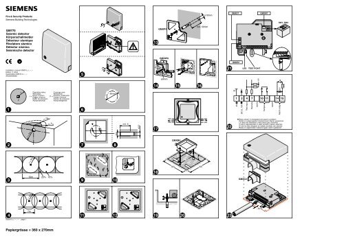
Coverage area fig. 1 + 2<br />
The coverage area is highly dependent on the material<br />
of the object to be monitored. Practical experience has<br />
shown that the operating radius for steel and reinforced<br />
concrete is «r» = 5m (fig. 1).<br />
The coverage area of the detector on strongroom<br />
walls may also extend to part of the ceiling, floor, or<br />
over corners if an homogeneous connection exists. In<br />
such cases the operating radius is reduced to ¾ of the<br />
range setting (fig. 2).<br />
Joints between two materials always damp the structure-borne<br />
noise transmission. One detector on the<br />
door and one on the body must always be installed.<br />
This also applies to entrance doors of strongrooms.<br />
For modular vault applications please refer to the special<br />
instructions (page 2) for modular vaults.<br />
Surveillance of the surface fig. 3 + 4<br />
To simplify the planning procedure on large surfaces,<br />
the circular coverage area can be considered as a<br />
square:<br />
For 75% surveillance of the surface: diameter within<br />
square = <strong>10</strong>m x <strong>10</strong>m = <strong>10</strong>0m 2 (fig. 3).<br />
For standard surveillance of the surface: square in<br />
circle = 7m x 7m = 49m 2 (fig. 4).<br />
It is of course also possible to choose intermediate values.<br />
Several detectors may be installed on the same object.<br />
Installation<br />
Opening the detector fig. 5<br />
1. Unscrew the captive screw and lift off the metal cover<br />
carefully.<br />
2. Disconnect the covers anti-drilling foil from detector<br />
body.<br />
The seismic sensor is now exposed.<br />
Fastening the detector fig. 5<br />
Use only the two pre-assembled M4 cross-head screws<br />
provided in order to fix the detector.<br />
Direct mounting on steel fig. 6 to 8<br />
The detector can be installed directly on steel plates<br />
with a smooth surface. Ensure that any residual paint<br />
between the steel surface and the seismic sensor is<br />
completely removed and the mounting surface is level<br />
to within 0.1mm. If this is not possible, use mounting<br />
plate GMXP0.<br />
1. Remove residual paint from sensor installation site<br />
(fig. 6).<br />
2. Stick on drilling template and centerpunch drill holes<br />
(fig. 7).<br />
3. Drill only the two marked holes of 3.2mm dia. and tap<br />
M4 thread at least 6mm deep (fig. 8). Deburr threaded<br />
holes.<br />
0083<strong>19</strong>_c_−−_−− page 3<br />
Papiergrösse = 360 x 270mm<br />
4. Mount detector.<br />
Do not use silicon grease between sensor and object!<br />
Indirect installation with mounting plate GMXP0<br />
fig. 9 to <strong>12</strong><br />
In the case of uneven or hardened steel plates, weld on<br />
mounting plate GMXP0.<br />
1. Remove residual paint from the welding area (fig. 9).<br />
2. Weld mounting plate in four fixing points. Ensure correct<br />
positioning (fig. <strong>11</strong>).<br />
The welding symbol must be visible on the front of<br />
the mounting plate (fig. <strong>10</strong>).<br />
3. Weld along surfaces indicated. Tap off slag and remove<br />
weld spatter from the plate surface (fig. <strong>12</strong>).<br />
4. Mount detector.<br />
Do not use silicon grease between sensor and<br />
mounting plate!<br />
Installation on concrete using mounting plate<br />
GMXP0 fig. <strong>13</strong><br />
Never install the detector directly on a bare or plastered<br />
concrete surface, since bending forces may cause<br />
damage to the seismic sensor. Plaster of less than<br />
<strong>10</strong>mm need not be removed.<br />
1. Drill centre hole <strong>10</strong>mm dia. at least 50mm deep using<br />
a sintered carbide bit (fig. <strong>13</strong>).<br />
2. Insert metal plug into drilled hole flush with the concrete<br />
surface. Use metal plugs only!<br />
3. Ensure that the mounting plate is correctly positioned.<br />
Press the mounting plate onto surface, knock<br />
in screw with plug and tighten well. The plate should<br />
no longer be capable of rotation.<br />
4. Mount detector.<br />
Do not use silicon grease between sensor and<br />
mounting plate!<br />
Recessed mounting with wall recess plate<br />
GMXW0 fig. <strong>14</strong> to <strong>16</strong><br />
1. Drill 9mm dia. hole in wooden concrete mould.<br />
2. Fasten the wall recess set by inserting threaded bolt<br />
and tightening wing nut (fig. <strong>14</strong>).<br />
3. Push the installation conduit through the polystyrene<br />
block.<br />
4. After removing mould, unscrew threaded bolt.<br />
Scrape out polystyrene and cut off conduit flush (fig.<br />
<strong>15</strong>).<br />
5. Mount detector.<br />
6. Mount cover plate (fig. <strong>16</strong>).<br />
Cable feed in wall box and floor box fig. <strong>17</strong><br />
Insert cable with reserve loop into the box. Ensure appropriate<br />
cable length when drawing the cable in.<br />
Installation in floor box GMXB0 fig. <strong>18</strong> to <strong>20</strong><br />
To install the floor box GMXB0, a recess with a base<br />
area of at least 300 x 300mm and a depth of 80mm is<br />
required (fig. <strong>18</strong>). Use a polystyrene block to keep this<br />
recess open when pouring in the wet concrete.<br />
Two threaded bolts M6x<strong>10</strong>0mm screwed into metal<br />
plugs provide the acoustic connection between the detector<br />
and the concrete floor.<br />
1. Level floor box using the nuts on the two threaded<br />
bolts. Fix position finally by tightening the lock nuts<br />
(fig. <strong>19</strong>).<br />
2. Feed installation conduits through sealing sleeves.<br />
Fill recess with wet cement.<br />
3. Pull cable through and thoroughly seal the entry<br />
openings for protection against moisture (fig. <strong>20</strong>).<br />
4. Mount the detector.<br />
5. Fit cover plate. Cut out wood or carpet floor covering<br />
and stick to cover plate.<br />
Installation accessory<br />
GMXC2 Conduit connection sleeve fig. <strong>23</strong><br />
The function of the GMXC2 conduit connection sleeve<br />
is to ensure fixed and secure connection of surfacemounted<br />
conduits of an outside diameter of up to <strong>16</strong>mm.<br />
Smaller-size surface-mounted conduits may require fitting<br />
of an appropriate transition sleeve of a maximum<br />
outside diameter of <strong>16</strong>mm.<br />
To fit the conduit connection sleeve, proceed as follows:<br />
1. Route the surface-mounted conduit to within about<br />
5mm of the detector housing and fit the conduit connection<br />
sleeve onto the surface-mounted conduit (fig.<br />
<strong>23</strong>).<br />
2. Wire the connecting cable and secure in place at the<br />
detector by a cable strap (fig. <strong>21</strong>, <strong>23</strong>).<br />
3. Knock out the entire cable entry in the plastic section.<br />
4. Fit the detector housing onto the conduit connection<br />
and detector, tighten the housing screw.<br />
Programming<br />
After the detector housing has been opened, use the<br />
switches to select the respective settings.<br />
SW1, SW2<br />
1 2<br />
ON<br />
OFF<br />
Application settings, SW1 and SW2<br />
Select the sensitivity setting to suit the application, the<br />
material and the object with the associated interference.<br />
Important: During commissioning, be sure to check for<br />
function-related noise (see ”Commissioning”).<br />
Settings on the detector<br />
Concrete 4.0m<br />
Steel 2.0m<br />
LWS 2.0m<br />
User Mode, with GMSW7 SensTool<br />
1 2<br />
1 2<br />
1 2<br />
1 2<br />
ON<br />
OFF<br />
ON<br />
OFF<br />
ON<br />
OFF<br />
ON<br />
OFF<br />
Remote controlled sensitivity reduction fig. <strong>22</strong><br />
An additional feature of this detector is a sensitivity reduction<br />
input at terminal 7 ”Remote” which can be remotely<br />
activated if required.<br />
Using a LOW signal (0V), the detector is reduced to<br />
about 1/8 of the sensitivity setting for as long as there is<br />
heavy functional noise by means of a touch-sensitive<br />
switch on the opening device during operation of daynight<br />
deposit.<br />
Open control input is HIGH (internal pull-up resistor).<br />
Attention VdS note: When the control input terminal 7<br />
”Remote” is used to reduce the sensitivity, then the<br />
compliance with the relevant VdS provisions in connection<br />
with the system must be checked, or accepted by<br />
the VdS, respectively.<br />
Test input fig. <strong>22</strong><br />
The test input terminal 4 is used for the functional testing<br />
of the seismic detector together with the GMXS1 or<br />
GMXS5 test transmitter.<br />
With TEST ON the functional test is run once and a positive<br />
test result is output to the alarm relay.<br />
Open control input is HIGH (internal pull-up resistor).<br />
LED<br />
During commissioning or when changing operating<br />
mode the red LED flashes until the detector is ready for<br />
operation.<br />
Lights on alarm condition for approx. 2.5s.<br />
Commissioning<br />
If the GMXS1 test transmitter is to be used, it must be<br />
connected before power is switched on.<br />
Procedure:<br />
1. Switch on voltage − wait 1 minute − the detector is<br />
ready for operation.<br />
2. Functional check: Simulate an attack signal in the supervised<br />
area, for example scratch lightly with a<br />
screwdriver or test signal GMXS1/GMXS5 − the detector<br />
should trigger an alarm.<br />
3. Interference checks: Connect an universal measuring<br />
instrument (impedance ≥<strong>20</strong>kΩ) between terminal<br />
1 (0V) and “TEST POINT” for integrator signal:<br />
− quiescent level . . . . . . . . . . . . . . . . . . . . . 0V<br />
− integration start . . . . . . . . . . . . . . . . . . . . 1.0V<br />
− alarm threshold (without load) . . . . 3.0V<br />
4. On the detector, remove the jumper above the connection<br />
of the anti-drilling foil.<br />
5. Connect the connector of the cover’s anti-drilling foil<br />
to the detector.<br />
6. Carefully close the cover, tightening the housing<br />
screw.<br />
Tamper seal of the detector<br />
If tamper seal of the detector is specified:<br />
Apply an anti-tamper seal over the detector cover screw<br />
hole.<br />
SensTool GMSW7<br />
The SensTool software allows operating parameters to<br />
be set individually. In addition, current information such<br />
as integrator signals can be viewed and stored.<br />
The following additional settings are possible, depending<br />
on the application, material and object, with corresponding<br />
interferences:<br />
Steel<br />
1.5m<br />
2.0m<br />
2.5m<br />
Detector sensitivity y<br />
Concrete 4.0m<br />
LWS<br />
low<br />
Shock sensitivityy mid<br />
high<br />
5.0m<br />
1.5m<br />
2.0m<br />
Recommended sensitivity settings<br />
The following approximate values can be used as reference<br />
values for the setting of the seismic detector:<br />
Application Sensitivity Shock<br />
Autom. cash dispenser, Day/night deposit,<br />
Safe door<br />
with havy functional related noises<br />
Armoured safe, Strongroom door<br />
with functional related noises<br />
Strongroom, Modular vault<br />
with light interferences<br />
Strongroom, Modular vault<br />
with low interferences<br />
Strongroom, Modular vault<br />
with minimum interferences<br />
Synthetic armoured system:<br />
autom. cash dispenser<br />
with functional related noises<br />
Synthetic armoured system:<br />
modular vault<br />
with minimum interferences<br />
Steel<br />
1.5m<br />
Steel<br />
2.0m<br />
Concrete<br />
2.5m<br />
Concrete<br />
4.0m<br />
Concrete<br />
5.0m<br />
LWS<br />
1.5m<br />
LWS<br />
2.0m<br />
mid<br />
mid<br />
high<br />
high<br />
high<br />
high<br />
high<br />
Maintenance<br />
Test detectors regularly (at least once a year) for operation<br />
and firm mounting.<br />
Approvals<br />
CE . . . . . . . . . . . . . . . . . . . . . . . . . . . . . . . . . . . . . . . . . . . . conforms<br />
VdS approval, class C . . . . . . . . . . . . . . . . . . . . . applied for<br />
Any national approval requirements relating to the application<br />
of the product must be complied with.<br />
Technical data<br />
Detector<br />
Supply voltage (nom. <strong>12</strong>VDC) . . . . . . . . . . . . . . . . 8.0...<strong>16</strong>.0VDC<br />
Current consumption (at <strong>12</strong>DC, quiescent) . . . . . . . . . typ. 3mA<br />
− alarm condition . . . . . . . . . . . . . . . . . . . . . . . . . . . . . . . . . . . . . 5mA<br />
Alarm output, terminals <strong>14</strong>+<strong>15</strong>:<br />
Semiconductor relay . . . . . opens on alarm and/or low voltage<br />
− contact load . . . . . . . . . . . . . . . . . . . 30VDC/<strong>10</strong>0mA, ohmic load<br />
− series resistance . . . . . . . . . . . . . . . . . . . . . . . . . . . . . . . . . . ≤45Ω<br />
Alarm holding time . . . . . . . . . . . . . . . . . . . . . . . . . . . . . . . . . . . . 2.5s<br />
Sabotage surveillance:<br />
Tamper, terminals <strong>10</strong>+<strong>11</strong>:<br />
− microswitches for cover + body . . . . . . . . . opens on tamper<br />
− contact load . . . . . . . . . . . . . . . . . . . . . . . . . . . . . . . 30VDC/<strong>10</strong>0mA<br />
Supply voltage . . . . . . . . . . . . . . . . . . . . . . . . . . .
Körperschallmelder GM770<br />
Montage<br />
Anwendung<br />
Der GM770 ist ein Körperschallmelder mit neuen Detektions-<br />
und Parameterisierungseigenschaften.<br />
Die Detektion ist verbessert durch das patentierte<br />
Störsignalfilter und den neuen Clock-Filter.<br />
Der Melder kann zusammen mit Ultraschallmeldern<br />
eingesetzt werden.<br />
Der Körperschallmelder GM770 eignet sich für das<br />
Überwachen von<br />
− Kassenschränken,<br />
− Tresormauern,<br />
− Elemente-Tresoren,<br />
− Tresorraumtüren,<br />
− Geldausgabeautomaten,<br />
− Stahl-Leichtgewichtbauweise (LWS) (Kunststoffpanzerungssysteme)<br />
auf Angriffe mit allen heute bekannten Einbruchwerkzeugen<br />
wie Diamantkronenbohrern, hydraulischen<br />
Presswerkzeugen, Sauerstofflanzen und ebenso auf<br />
Angriffe mit Sprengstoffen.<br />
Wirkbereich Fig. 1 + 2<br />
Der Wirkbereich ist stark vom Material des zu überwachenden<br />
Objektes abhängig. Aufgrund praktischer Erfahrung<br />
gilt für Stahl und eisenarmierten Beton ein Wirkradius<br />
von «r» = 5m (Fig. 1).<br />
Die Wirkbereiche von Meldern an Tresorwänden können<br />
sich auch auf einen Teil der Decke oder des Bodens<br />
erstrecken, wenn die Armierungseisen gut miteinander<br />
verbunden sind. In solchen Fällen reduziert<br />
sich der Wirkradius auf ¾ des eingestellten Bereichs<br />
(Fig. 2).<br />
Fugen zwischen zwei Materialien stellen immer eine<br />
Dämpfung für die Körperschallübertragung dar. Daher<br />
grundsätzlich sowohl Türe wie Schrank mit Meldern<br />
ausrüsten. Dies gilt auch für Eingangstüren von<br />
Tresorräumen.<br />
Bei Anwendung auf Elemente-Tresoren beachten Sie<br />
bitte die Anweisung (Seite 2) für Elemente-Tresore.<br />
Flächenüberwachung Fig. 3 + 4<br />
Zum Erleichtern der Projektierung auf großen Flächen<br />
den kreisförmigen Wirkbereich in ein Quadrat umwandeln:<br />
Für eine 75%-ige Flächenüberwachung Durchmesser<br />
im Quadrat = <strong>10</strong>m x <strong>10</strong>m = <strong>10</strong>0m 2 (Fig. 3).<br />
Für eine Standard Flächenüberwachung Quadrat im<br />
Kreis = 7m x 7m = 49m 2 (Fig.4).<br />
Natürlich können auch Zwischenwerte gewählt werden.<br />
Mehrere Melder beeinflussen sich gegenseitig nicht.<br />
Installation<br />
Öffnen des Melders Fig. 5<br />
1. Die unverlierbare vordere Schraube lösen und den<br />
Metalldeckel vorsichtig abheben.<br />
2. Stecker der Bohrschutzfolie abziehen.<br />
Der Körperschallsensor liegt nun frei.<br />
Befestigen des Melders Fig. 5<br />
Zur Befestigung des Melders die beiden vormontierten<br />
Kreuzschlitzschrauben M4 verwenden.<br />
Direkte Montage auf Stahl Fig. 6 − 8<br />
Auf Stahlplatten mit glatter Oberfläche kann der Melder direkt<br />
montiert werden. Dabei beachten, dass jegliche Farbresten<br />
zwischen Stahloberfläche und Körperschall-Sensor<br />
restlos entfernt sind und die Montageoberfläche eine<br />
Ebenheit besser 0,1mm aufweist. Ist dies nicht möglich,<br />
die Befestigungsplatte GMXP0 verwenden.<br />
1. Von der Montagestelle für den Sensor alle Farbreste<br />
entfernen (Fig. 6).<br />
2. Die Montageschablone aufkleben und die beiden<br />
Bohrstellen ankörnen (Fig. 7).<br />
3. Bohren Sie nur die zwei markierten Löcher mit einem<br />
Durchmesser von 3,2mm, schneiden Sie das<br />
M4-Gewinde mindestens 6mm tief (Fig. 8). Die Gewindelöcher<br />
entgraten.<br />
0083<strong>19</strong>_c_−−_−− page 4<br />
Papiergrösse = 360 x 270mm<br />
4. Montieren Sie den Melder.<br />
Zwischen dem Sensor und dem Objekt darf kein Silikonfett<br />
aufgetragen werden!<br />
Indirekte Montage mit Befestigungsplatte GMXP0<br />
Fig. 9 − <strong>12</strong><br />
Bei unebenen und gehärteten Stahlplatten die Befestigungsplatte<br />
GMXP0 aufschweißen.<br />
1. Von der Schweißstelle die gesamte Farbe entfernen<br />
(Fig. 9).<br />
2. Die Befestigungsplatte an vier Punkten anheften.<br />
Achten Sie auf die richtige Positionierung (Fig. <strong>11</strong>).<br />
Das Schweißsymbol muss auf der Vorderseite der<br />
Befestigungsplatte zu sehen sein (Fig. <strong>10</strong>).<br />
3. Die Schweißnähte entlang der angegebenen Stellen<br />
anbringen. Die Schlacke abklopfen und Schweißspritzer<br />
von der Plattenoberfläche entfernen (Fig. <strong>12</strong>).<br />
4. Montieren Sie den Melder.<br />
Zwischen dem Sensor und der Befestigungsplatte<br />
darf kein Silikonfett aufgetragen werden!<br />
Montage auf Beton mit Befestigungsplatte GMXP0<br />
Fig. <strong>13</strong><br />
Der Melder darf nicht direkt auf eine rohe oder verputzte<br />
Betonoberfläche montiert werden, da durch Verbiegungskräfte<br />
der Körperschallsensor beschädigt werden<br />
könnte. Verputz von weniger als <strong>10</strong>mm muss nicht<br />
entfernt werden.<br />
1. Mit einem Hartmetallbohrer ein Mittelloch mit einem<br />
Durchmesser von <strong>10</strong>mm und einer Tiefe von mindestens<br />
50mm bohren (Fig. <strong>13</strong>).<br />
2. Einen Metalldübel bündig zur Betonoberfläche in das<br />
gebohrte Loch einsetzen. Es dürfen nur Metalldübel<br />
verwendet werden!<br />
3. Stellen Sie sicher, dass die Befestigungsplatte richtig<br />
positioniert ist. Drücken Sie die Befestigungsplatte<br />
auf die Oberfläche, setzen Sie die Schraube ein, und<br />
ziehen Sie sie fest an. Die Platte darf nicht mehr verdreht<br />
werden können.<br />
4. Montieren Sie den Melder.<br />
Zwischen dem Sensor und der Befestigungsplatte<br />
darf kein Silikonfett aufgetragen werden!<br />
Unterputzmontage mit Wandeinbau-Set GMXW0<br />
Fig. <strong>14</strong> − <strong>16</strong><br />
1. In die Holzschalung ein Loch mit einem Durchmesser<br />
von 9mm bohren.<br />
2. Die Wandeinbauplatte befestigen, indem die Gewindestange<br />
eingesetzt und die Flügelmutter festgezogen<br />
wird (Fig. <strong>14</strong>).<br />
3. Das Installationsrohr durch den Schaumstoffklotz<br />
schieben.<br />
4. Nach dem Entfernen der Schalung die Gewindestange<br />
herausschrauben. Den Schaumstoff herauskratzen<br />
und das Installationsrohr bündig abschneiden<br />
(Fig. <strong>15</strong>).<br />
5. Montieren Sie den Melder.<br />
6. Montieren Sie die Abdeckplatte (Fig. <strong>16</strong>).<br />
Kabelführung in Wand- und Bodendose Fig. <strong>17</strong><br />
Das Kabel muss mit einer Reserveschlaufe in die Dose<br />
eingelegt werden. Beim Einziehen des Kabels auf eine<br />
ausreichende Kabellänge achten.<br />
Montage in Bodendose GMXB0 Fig. <strong>18</strong> − <strong>20</strong><br />
Für den Einbau der Bodendose GMXB0 ist eine Aussparung<br />
mit einer Grundfläche von mindestens 300mm<br />
x 300mm und einer Tiefe von 80mm erforderlich (Fig.<br />
<strong>18</strong>). Diese Aussparung mit einem Schaumstoffklotz<br />
beim Ausgießen des Bodens freihalten.<br />
Zwei in Metalldübel geschraubte Gewindebolzen<br />
M6x<strong>10</strong>0mm stellen die akustische Verbindung zwischen<br />
dem Melder und dem Betonboden her.<br />
1. Die Bodendose mit den Muttern an den beiden Gewindebolzen<br />
nivellieren. Zum Fixieren anschliessend<br />
die Kontermuttern festziehen (Fig. <strong>19</strong>).<br />
2. Die Installationsrohre durch die Dichtungsmuffen<br />
einführen. Die Aussparung mit dünnflüssigem Beton<br />
ausgießen.<br />
3. Das Kabel einziehen. Die Einführungsöffnungen<br />
müssen zum Schutz vor Feuchtigkeit sorgfältig abgedichtet<br />
werden (Fig. <strong>20</strong>).<br />
4. Montieren Sie den Melder.<br />
5. Die Abdeckplatte anbringen. Holz- oder Teppichbeläge<br />
ausschneiden und auf die Abdeckplatte kleben.<br />
Montagezubehör<br />
Rohranschluss-Muffe GMXC2 Fig. <strong>23</strong><br />
Die Rohranschlussmuffe GMXC2 dient dazu, einen festen<br />
und gesicherten Anschluss von Aufputzrohren mit<br />
einem Aussendurchmesser von bis zu <strong>16</strong>mm herzustellen.<br />
Bei kleineren Aufputzrohren ist unter Umständen<br />
der Einsatz einer entsprechenden Übergangsmuffe<br />
mit einem maximalen Aussendurchmesser von<br />
<strong>16</strong>mm erforderlich.<br />
Die Rohranschlussmuffe wird folgendermaßen eingebaut:<br />
1. Das Aufputzrohr wird bis etwa 5mm vor das Meldergehäuse<br />
geführt und die Rohranschlussmuffe auf<br />
das Aufputzrohr aufgesetzt (Fig. <strong>23</strong>).<br />
2. Das Anschlusskabel wird verdrahtet und mit einem<br />
Kabelbinder am Melder fixiert (Fig. <strong>21</strong>, <strong>23</strong>).<br />
3. Den gesamten Kabeleinführungsteil im Kunststoff-<br />
Anschlussstück herausbrechen.<br />
4. Das Meldergehäuse auf den Rohranschluss und den<br />
Melder aufsetzen, und die Gehäuseschraube festziehen.<br />
Programmierung<br />
Nach dem Öffnen des Meldergehäuses entsprechende<br />
Einstellungen mit den Schaltern wählen.<br />
SW1, SW2<br />
1 2<br />
ON<br />
OFF<br />
Applikationseinstellungen, SW1 und SW2<br />
Je nach Anwendung und Material wird die entsprechende<br />
Einstellung gewählt.<br />
Wichtig: Bei Inbetriebnahme immer auf funktionsbedingte<br />
Geräusche überprüfen (siehe ”Inbetriebnahme”).<br />
Einstellungen am Melder<br />
Beton 4,0m<br />
Stahl 2,0m<br />
LWS 2,0m<br />
User Mode, mit GMSW7 SensTool<br />
1 2<br />
1 2<br />
1 2<br />
1 2<br />
ON<br />
OFF<br />
ON<br />
OFF<br />
ON<br />
OFF<br />
ON<br />
OFF<br />
Fernbedienbare Reduktion der Empfindlichkeit<br />
Fig. <strong>22</strong><br />
Zusätzlich verfügt dieser Melder auf Klemme 7 ”Remote”<br />
über einen Empfindlichkeitsreduktions-Eingang,<br />
welcher bei Bedarf extern angesteuert werden kann.<br />
Der Melder wird mit einem LOW-Signal auf etwa 1/8 der<br />
eingestellten Empfindlichkeit reduziert, solange funktionsbedingte<br />
starke Geräusche vorliegen, z.B. mit Kontaktschalter<br />
an Einwurfvorrichtung während der Bedienung<br />
von Tag-Nacht-Tresoranlagen.<br />
Offener Steuereingang ist HIGH (interner «Pullup»-Widerstand).<br />
Achtung VdS-Hinweis: Wird der Steuereingang<br />
Klemme 7 ”Remote” zur Empfindlichkeitsreduktion benutzt,<br />
so muss die Übereinstimmung mit den einschlägigen<br />
VdS-Vorschriften im Systemzusammenhang geprüft,<br />
bzw. vom VdS akzeptiert werden.<br />
Testeingang Fig. <strong>22</strong><br />
Der Testeingang Klemme 4 ”Test” dient dem Funktionstest<br />
des Körperschallmelders zusammen mit dem Prüfsender<br />
GMXS1 oder GMXS5.<br />
Bei TEST EIN wird der Funktionstest einmal durchgeführt<br />
und ein positives Testresultat auf das Alarmrelais<br />
ausgegeben (identisch mit Alarm).<br />
Offener Steuereingang ist HIGH (interner «Pullup»-Widerstand).<br />
LED-Anzeige<br />
Bei der Inbetriebnahme oder beim Umschalten der Applikationseinstellung<br />
blinkt die rote LED bis die Initialisierung<br />
abgeschlossen ist.<br />
Bei Alarm leuchtet die LED für ca. 2,5s.<br />
Inbetriebnahme<br />
Wenn der Prüfsender GMXS1 verwendet wird, muss er<br />
bevor die Spannung zugeschaltet wird angeschlossen<br />
werden.<br />
Vorgehen:<br />
1. Spannung zuschalten − 1 Min. warten − Melder ist betriebsbereit.<br />
2. Funktionsprüfung: Einbruchsignal im überwachten<br />
Wirkbereich simulieren, z.B. mit Schraubenzieher<br />
kratzen oder Prüfsignal GMXS1/GMXS5 − Melder<br />
löst Alarm aus.<br />
3. Überprüfen von Störeinflüssen:<br />
Messinstrument (Ri ≥<strong>20</strong>kΩ) an Klemme 1 (0V) und<br />
”TEST POINT” für analoges Integrationssignal:<br />
− Ruhepegel . . . . . . . . . . . . . . . . . . . . . . . . . 0V<br />
− Integrationsstart . . . . . . . . . . . . . . . . . 1,0V<br />
− Alarmschwelle (unbelastet) . . . . . 3,0V<br />
4. Am Melder die Steckbrücke über dem Anschluss der<br />
Bohrschutzfolie entfernen.<br />
5. Stecker der Deckel-Bohrschutzfolie mit dem Melder<br />
verbinden.<br />
6. Deckel vorsichtig schließen, die Gehäuseschraube<br />
festziehen.<br />
Plombieren des Melders<br />
Wenn das Plombieren des Melders vorgeschrieben ist:<br />
Eine Klebeplombe auf dem Schraubenloch des Melderdeckels<br />
anbringen.<br />
SensTool GMSW7<br />
Die SensTool-Software ermöglicht Betriebsparameter<br />
individuell einzustellen. Auch können aktuelle Informationen<br />
wie z.B. das Integrationssignal angesehen und<br />
gespeichert werden.<br />
Folgende zusätzliche Einstellungen können je nach Anwendung,<br />
Material und Objekt mit entsprechenden<br />
Störeinflüssen vorgenommen werden:<br />
Stahl<br />
1,5m<br />
2,0m<br />
2,5m<br />
Melder-Empfindlichkeit p<br />
Beton 4,0m<br />
LWS<br />
niedrig<br />
Erschütterungs-Empfindlichkeit g p<br />
mittel<br />
hoch<br />
5,0m<br />
1,5m<br />
2,0m<br />
Empfohlene Empfindlichkeits-Einstellungen<br />
Folgende Angaben können als Richtwerte für die Einstellung<br />
des Körperschallmelders beigezogen werden:<br />
Anwendung Empfindlichkeit<br />
Bankomat, Tag/Nacht/-Tresoranlage,<br />
Geldschranktüre<br />
starke funktionsbedingte Geräusche<br />
Panzer-Geldschrank, Tresorraumtüre<br />
funktionsbedingte Geräusche<br />
Tresorraum, Elemente-Tresor<br />
leichte Störeinflüsse<br />
Tresorraum, Elemente-Tresor<br />
geringe Störeinflüsse<br />
Tresorraum, Elemente-Tresor<br />
minimale Störeinflüsse<br />
Kunstoffpanzerungssystem:<br />
Geldautomat<br />
funktionsbedingte Geräusche<br />
Kunstoffpanzerungssystem:<br />
Elemente-Tresor<br />
minimale Störeinflüsse<br />
Stahl<br />
1,5m<br />
Stahl<br />
2,0m<br />
Beton<br />
2,5m<br />
Beton<br />
4,0m<br />
Beton<br />
5,0m<br />
LWS<br />
1,5m<br />
LWS<br />
2,0m<br />
Erschütterungen<br />
mittel<br />
mittel<br />
hoch<br />
hoch<br />
hoch<br />
hoch<br />
hoch<br />
Unterhalt<br />
Melder regelmäßig (min. 1mal pro Jahr) auf Funktion<br />
und Befestigung prüfen.<br />
Zulassungen<br />
CE . . . . . . . . . . . . . . . . . . . . . . . . . . . . . . . . . . . . . . . . . . . . . . konform<br />
VdS-Anlageklasse C . . . . . . . . . . . . . . . . . . . . . . eingereicht<br />
Nationale Zulassungsbedingungen, welche die Anwendung<br />
des Produktes betreffen, sind einzuhalten.<br />
Technische Daten<br />
Melder<br />
Speisespannung (nom. <strong>12</strong>V−) . . . . . . . . . . . . . . . . . . 8,0...<strong>16</strong>,0V−<br />
Stromaufnahme (bei <strong>12</strong>V−, Ruhe) . . . . . . . . . . . . . . . . typ. 3mA<br />
− Alarmzustand . . . . . . . . . . . . . . . . . . . . . . . . . . . . . . . . . . . . . 5mA<br />
Alarmausgang, Klemmen <strong>14</strong>+<strong>15</strong>:<br />
− Halbleiter-Relais . . . . . . . öffnet bei Alarm + Unterspannung<br />
− Kontaktbelastung . . . . . . . . . . . . 30V−/<strong>10</strong>0mA, ohmsche Last<br />
− Seriewiderstand . . . . . . . . . . . . . . . . . . . . . . . . . . . . . . . . . . . ≤45Ω<br />
− Alarmhaltezeit . . . . . . . . . . . . . . . . . . . . . . . . . . . . . . . . . . . . . . 2,5s<br />
Sabotageüberwachung:<br />
Tamper, Klemmen <strong>10</strong>+<strong>11</strong><br />
− Mikroschalter, Deckel + Boden . . . . . . . öffnet bei Sabotage<br />
− Kontaktbelastung . . . . . . . . . . . . . . . . . . . . . . . . . . . 30V−/<strong>10</strong>0mA<br />
Spannungsüberwachung . . . . . . . . . . . . . . . . . . . .