Download (5.4 MB) - Prolyte
Download (5.4 MB) - Prolyte
Download (5.4 MB) - Prolyte

Create successful ePaper yourself
Turn your PDF publications into a flip-book with our unique Google optimized e-Paper software.
Version 1, January 2010<br />
PROLYTE GROUP<br />
Industriepark 9<br />
9351 PA Leek, The Netherlands<br />
phone : +31 (0)594 85 15 15<br />
fax : +31 (0)594 85 15 16<br />
e-mail : info@prolyte.com<br />
website : www.prolyte.com<br />
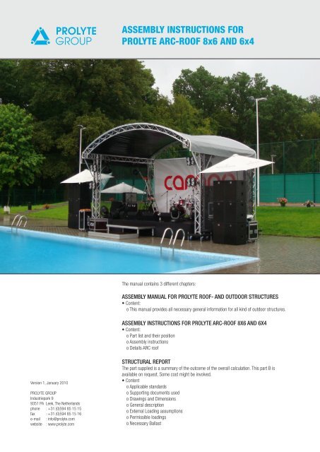
ASSE<strong>MB</strong>LY INSTRUCTIONS FOR<br />
PROLYTE ARC-ROOF 8x6 AND 6x4<br />
The manual contains 3 different chapters:<br />
ASSE<strong>MB</strong>LY MANUAL FOR PROLYTE ROOF- AND OUTDOOR STRUCTURES<br />
• Content:<br />
o This manual provides all necessary general information for all kind of outdoor structures.<br />
ASSE<strong>MB</strong>LY INSTRUCTIONS FOR PROLYTE ARC-ROOF 8X6 AND 6X4<br />
• Content:<br />
o Part list and their position<br />
o Assembly instructions<br />
o Details ARC roof<br />
STRUCTURAL REPORT<br />
The part supplied is a summary of the outcome of the overall calculation. This part B is<br />
available on request. Some cost might be involved.<br />
• Content<br />
o Applicable standards<br />
o Supporting documents used<br />
o Drawings and Dimensions<br />
o General description<br />
o External Loading assumptions<br />
o Permissible loadings<br />
o Necessary Ballast
Assembly Manual <strong>Prolyte</strong> Roof and outdoor structures<br />
Read this manual carefully and understand all of it’s contents before you assemble the <strong>Prolyte</strong> Roof and outdoor structures<br />
CONTENTS<br />
1. ARC 8X6 .................................................................................................................................................................................. 2<br />
page 2<br />
1.1 PART LIST AND THEIR POSITIONS .............................................................................................................................3<br />
1.2 ASSE<strong>MB</strong>LY INSTRUCTIONS PROLYTE ARC 8X6 ......................................................................................................... 4<br />
2. ARC 6X4 ...................................................................................................................................................................................9<br />
2.1 PART LIST AND THEIR POSITIONS ...........................................................................................................................11<br />
2.2 ASSE<strong>MB</strong>LY INSTRUCTIONS PROLYTE ARC 6X4 ........................................................................................................12<br />
3. DETAILS ARC 8X6 AND ARC 6X4 ...............................................................................................................................................16<br />
Copyright Restrictions<br />
The contents of this manual are property of <strong>Prolyte</strong> Group and are protected under Dutch copyright statutes. Reproduction or redistribution is prohibited<br />
without the express written consent of the <strong>Prolyte</strong> Group. Photos and illustrations should not be used without permission. Contact info@prolyte.com to obtain<br />
permission. However, under the doctrine of “fair use” limited copying of text is permitted without prior approval for teaching and research purposes. In those<br />
cases, <strong>Prolyte</strong> Group requests the courtesy of citation. Use of the <strong>Prolyte</strong> Group logos is prohibited without written permission.<br />
ASSE<strong>MB</strong>LY INSTRUCTIONS PROLYTE ARC-ROOF 8x6<br />
2<br />
3<br />
2<br />
8<br />
28 or 38<br />
37<br />
6 3x20 15 27 or 36 19 2x20 18 15 17 7<br />
4 28 or 37 29+30 or 38+39+40<br />
PROLYTE GROUP © 2010<br />
<strong>Prolyte</strong> has made every effort to ensure the accuracy of this manual, no liability will be accepted for errors.<br />
<strong>Prolyte</strong> reserves the right to change or alter their products or manuals without prior notice.<br />
No part of this manual may be reproduced in any form or by any means without prior written permission.<br />
<strong>Prolyte</strong> Group - phone +31 (0)594 85 15 15 - fax +31 (0)594 85 15 16 - www.prolyte.com<br />
5<br />
16<br />
1<br />
1<br />
1<br />
10<br />
9
1.1 PART LIST AND THEIR POSITIONS<br />
Assembly Manual <strong>Prolyte</strong> Roof and outdoor structures<br />
Read this manual carefully and understand all of it’s contents before you assemble the <strong>Prolyte</strong> Roof and outdoor structures<br />
ARC STAGE 8x6<br />
No: Qty Code Description<br />
1 12 H30V-L100 100cm length<br />
2 4 H30V-L200 200cm length<br />
3 2 ARC-C017/2 T-joint with 2x eye<br />
4 1 ARC-C003/L 2way corner for arc-stage left<br />
5 1 ARC-C003/R 2way corner for arc-stage right<br />
6 1 ARC-C012/L 3-way special for arc-stage left<br />
7 1 ARC-C012/R 3-way special for arc-stage right<br />
8 2 ARC-C017 3-way T-joint for arc-stage<br />
9 4 MPT-004 Steel tower base section<br />
10 16 MPT-011 Shortoutrigger<br />
11 110 CCS6-600 Conical coupler<br />
12 150 CCS6-603 Conical spigot for CCS6-600<br />
13 120 CCS6-604 Conical spigot with M8 nut for CCS6-600<br />
14 150 CCS6-605 Safety R-spring for CCS6-603<br />
15 6 ARC-R0800-30 H30D arched truss + Kedar, R=800cm, 30dgr.<br />
16 8 T-48-ST120ST Tube 48x3 L=1200, with stabilizer clamps<br />
17 1 T-60-48-CW314CW Canopy support with quick release claws L=314cm<br />
18 1 T-60-48-PRESS-L242,5 Canopy support tube with special attachment<br />
19 3 Z-CCS6-S50-K Spacer 50mm + kedar<br />
20 6 CCS6-S50 Spacer 50mm<br />
21 1 CAN-ARC-TOP/F Canopy top front<br />
22 1 CAN-ARC-TOP/B Canopy top back<br />
23 12 RA-2T-200OE Ratchet, 1 ton endless, L=150<br />
24 2 T-51-OE300SP Tube 51x2 L=300, spigoted<br />
25 2 T-51-OE060OE Tube 51x2 L=060, non spigoted<br />
26 2 T-51-OE265OE Tube 51x2 L=265, non spigoted<br />
Rigging set<br />
27 4 RA-2T-600-HH Ratchet set 2T, 0,5m + 5.50m + hooks<br />
28 2 RA-2T-1100HH Ratchet set 2T, 0,5m +10.50m + hooks<br />
29 2 SS-2T-200 Soft steel 2ton WL=200cm black<br />
30 2 RI-SH3.2T Shackle 3.2 ton with bolt+nut<br />
Canopy for side / backwall<br />
Qty Qty Code Description<br />
31 1 CAN-ARC-0806/B CAN-ARC-0806 backwall 50%<br />
32 2 CAN-ARC-0806/S CAN-ARC-0806 sidewall 50%<br />
33 96 CAN-BUNGY/20 Rubber Bungy cord L=20cm + hook<br />
34 4 T-51-OE300SP Tube 51x2 L=300, spigoted<br />
35 3 T-51-OE260OE Tube 51x2 L=260, open end<br />
Rigging set for German market<br />
Qty Qty Code Description<br />
36 4 RA-2T-600-HH Ratchet set 2T, 0,5m + 5.50m + hooks<br />
37 2 SW-10-700EH Steelwire 6x19x10mm with eye/hook L=7,00m. Backwall<br />
38 2 CH-07-200HCSH Chain + spanner + shortener L=2,00 + 2x hook<br />
39 2 SS-2T-200 Soft steel 2ton WL=200cm black<br />
40 2 RI-SH3.2T Shackle 3.2 ton with bolt+nut<br />
page 3
Assembly Manual <strong>Prolyte</strong> Roof and outdoor structures<br />
Read this manual carefully and understand all of it’s contents before you assemble the <strong>Prolyte</strong> Roof and outdoor structures<br />
1.2 ASSE<strong>MB</strong>LING INSTRUCTIONS ARC-ROOF 8X6<br />
1) Assemble both up-downstage spans out of square H30V-trussing on the left and right sides of<br />
the construction (fig. 1).<br />
page 4<br />
(fig 1)<br />
6<br />
2<br />
8<br />
2) Assemble the arches. Make sure you put spacers (item no: 20) in between the joint of each arch.<br />
A special spacer with keder (item no: 19) is supplied for those chords which hold a keder.<br />
See detail B, page 35.<br />
7<br />
2<br />
3) After the arches are assembled mount them between the side spans. Make sure that the keder profile on the front arch sits on the<br />
outside. For the arches in middle and back the keder profile should sit at the back chord of the truss (fig. 2).<br />
(fig 2)<br />
15<br />
15<br />
PROLYTE GROUP © 2010<br />
<strong>Prolyte</strong> has made every effort to ensure the accuracy of this manual, no liability will be accepted for errors.<br />
<strong>Prolyte</strong> reserves the right to change or alter their products or manuals without prior notice.<br />
No part of this manual may be reproduced in any form or by any means without prior written permission.<br />
<strong>Prolyte</strong> Group - phone +31 (0)594 85 15 15 - fax +31 (0)594 85 15 16 - www.prolyte.com<br />
2<br />
3<br />
8<br />
4<br />
15<br />
2<br />
3<br />
5
4) Then mount the canopy support tubes as shown in detail B, page 35.<br />
(fig 3)<br />
DETAIL 2<br />
Assembly Manual <strong>Prolyte</strong> Roof and outdoor structures<br />
Read this manual carefully and understand all of it’s contents before you assemble the <strong>Prolyte</strong> Roof and outdoor structures<br />
18<br />
5) Take the 4 ratchet-straps (item no 28 or 36, page 20) and attach them to the eyes, which are welded in the corners and on the<br />
middle of each arch (see detail 1 & 2 below). Put them slightly and simultaneously under tension, t.i about 50 daN (= 50 kgf).<br />
(fig 4)<br />
DETAIL 1<br />
17<br />
DETAIL 2<br />
DETAIL 1<br />
page 5
Assembly Manual <strong>Prolyte</strong> Roof and outdoor structures<br />
Read this manual carefully and understand all of it’s contents before you assemble the <strong>Prolyte</strong> Roof and outdoor structures<br />
6) Pull the canopy through the kader profiles on top of the arches (fig. 5). Make sure this is done evenly and with care. To facilitate<br />
this processes use some Teflon spray on a regular basis. Also make sure that the keder profile is maintained. Burrs, damages or<br />
sharp edges will damage the canopy and reduce the life span dramatically.<br />
page 6<br />
(fig 5)<br />
7) Put the tubes through the sleeve in the canopy and attach the ratchets as shown in fig.6.<br />
Put the ratchet slightly under tension, not exceeding 50kgf per ratchet. There is no need to transfer the canopy into a drum skin.<br />
(fig 6)<br />
PROLYTE GROUP © 2010<br />
<strong>Prolyte</strong> has made every effort to ensure the accuracy of this manual, no liability will be accepted for errors.<br />
<strong>Prolyte</strong> reserves the right to change or alter their products or manuals without prior notice.<br />
No part of this manual may be reproduced in any form or by any means without prior written permission.<br />
<strong>Prolyte</strong> Group - phone +31 (0)594 85 15 15 - fax +31 (0)594 85 15 16 - www.prolyte.com
Assembly Manual <strong>Prolyte</strong> Roof and outdoor structures<br />
Read this manual carefully and understand all of it’s contents before you assemble the <strong>Prolyte</strong> Roof and outdoor structures<br />
8) Lifting the roof. This can be done on two ways:<br />
a) as the legs are constructed from H30V-L100 length trusses the roof can be lifted manually.<br />
By lifting alternating the left or right side a 100cm truss length can be stuck underneath each leg.<br />
NB! Make sure lifting is done evenly (fig.7).<br />
b) By means of 4 Genie lifts. In this case the required length for the legs can be mounted randomly<br />
(fig 7)<br />
9) By alternating this handling side-by-side each leg can be constructed out of 3 pcs of 100cm H30V truss.<br />
10) Attach the stabilizer tubes under 45 degree in each corner (item no: 16).<br />
11) Mount the base sections (item no: 8) to the truss by lifting the legs one by one.<br />
2<br />
3<br />
2<br />
8<br />
28 or 38<br />
(fig 8)<br />
37<br />
6 3x20 15 27 or 36 19 2x20 18 15 17 7<br />
4 28 or 37 29+30 or 38+39+40<br />
12) When all base sections are in place level the system by adjusting the screw jacks (item no: 10).<br />
Determine the highest point and start from there leveling the roof<br />
5<br />
16<br />
1<br />
1<br />
1<br />
10<br />
9<br />
page 7
Assembly Manual <strong>Prolyte</strong> Roof and outdoor structures<br />
Read this manual carefully and understand all of it’s contents before you assemble the <strong>Prolyte</strong> Roof and outdoor structures<br />
13) It is not necessary to lift the castor wheels from the ground. It is sufficient when the screw jacks touch the ground-surface. In case<br />
the structure is loaded, the castors wheels can’t be pressed any further and the screw jacks take the entire load.<br />
14) Attach the guy-wire set in the back side (items no 28, 29, 30).<br />
NOTE ! When built in Germany items 37, 38, 39, 40 should be used. See detail C, page 35.<br />
15) Now the stage can be built underneath the roof. Connect the legs to the stage, this can safe considerably in the total amount of<br />
ballast needed.<br />
16) Ballast must be placed aside the base sections (see figures 9.1, 9.2, 9.3) to prevent uplifting of the roof by wind forces. All<br />
additional loading, such as scaffolding or stage-elements fixed to the corner legs or the base sections, can be subtracted from the<br />
amount of counterweight needed.<br />
page 8<br />
Following examples can be used as ballast – depending on the local building codes and regulations:<br />
- Water tanks connected to the towers / base sections.<br />
- In case of a complete rigid stage structure (like a scaffolding stage), the total weight of the stage may be taken in account as<br />
ballast when connected properly to the towers.<br />
- Ground anchors.<br />
- Concrete blocks.<br />
- Canvas bags filled with sand, rubble.<br />
- Steel.<br />
(fig 9.1)<br />
17) After the ballast is applied the sidewall canopies can be mounted.<br />
18) The roof is now ready for use. Loads can be applied<br />
(fig 9.2)<br />
(fig 9.3)<br />
PROLYTE GROUP © 2010<br />
<strong>Prolyte</strong> has made every effort to ensure the accuracy of this manual, no liability will be accepted for errors.<br />
<strong>Prolyte</strong> reserves the right to change or alter their products or manuals without prior notice.<br />
No part of this manual may be reproduced in any form or by any means without prior written permission.<br />
<strong>Prolyte</strong> Group - phone +31 (0)594 85 15 15 - fax +31 (0)594 85 15 16 - www.prolyte.com
2<br />
15<br />
3<br />
39<br />
40<br />
CONTENTS<br />
Assembly Manual <strong>Prolyte</strong> Roof and outdoor structures<br />
Read this manual carefully and understand all of it’s contents before you assemble the <strong>Prolyte</strong> Roof and outdoor structures<br />
2. ARC 6X4 ...................................................................................................................................................................................9<br />
2.1 PART LIST AND THEIR POSITIONS ...........................................................................................................................10<br />
2.2 ASSE<strong>MB</strong>LY INSTRUCTIONS PROLYTE ARC 6X4 ........................................................................................................11<br />
3. DETAILS ARC 8X6 AND ARC 6X4 ...............................................................................................................................................16<br />
Copyright Restrictions<br />
The contents of this manual are property of <strong>Prolyte</strong> Group and are protected under Dutch copyright statutes. Reproduction or redistribution is prohibited<br />
without the express written consent of the <strong>Prolyte</strong> Group. Photos and illustrations should not be used without permission. Contact info@prolyte.com to obtain<br />
permission. However, under the doctrine of “fair use” limited copying of text is permitted without prior approval for teaching and research purposes. In those<br />
cases, <strong>Prolyte</strong> Group requests the courtesy of citation. Use of the <strong>Prolyte</strong> Group logos is prohibited without written permission.<br />
2.0 ASSE<strong>MB</strong>LY INSTRUCTIONS PROLYTE ARC-ROOF 6x4<br />
6 14 28 or 38<br />
22 23 16 17 14 7<br />
4 29 30+31 or 40+41+42<br />
5<br />
15<br />
1<br />
1<br />
1<br />
9<br />
8<br />
page 9
Assembly Manual <strong>Prolyte</strong> Roof and outdoor structures<br />
Read this manual carefully and understand all of it’s contents before you assemble the <strong>Prolyte</strong> Roof and outdoor structures<br />
2.1 PART LIST AND THEIR POSITIONS<br />
ARC STAGE 6x4<br />
No: Qty Code Description<br />
1 12 H30V-L100 100cm length<br />
2 2 H30V-L300 300cm length<br />
3 2 ARC-C017/2 T-joint with 2x eye<br />
4 1 ARC-C003/L 2way corner for arc-stage left<br />
5 1 ARC-C003/R 2way corner for arc-stage right<br />
6 1 ARC-C012/L 3-way special for arc-stage left<br />
7 1 ARC-C012/R 3-way special for arc-stage right<br />
8 4 MPT-004 Steel tower base section<br />
9 16 MPT-011 Shortoutrigger<br />
10 52 CCS6-600 Conical coupler<br />
11 78 CCS6-603 Conical spigot for CCS6-600<br />
12 58 CCS6-604 Conical spigot for CCS6-600 with M 8 nut<br />
13 78 CCS6-605 Safety R-spring for CCS6-603<br />
14 4 ARC-R600-30 H30D arched truss + Kedar, R=600cm, 30dgr.<br />
15 8 T-48-ST120ST Tube 48x3 L=1200, with stabilizer clamps<br />
16 1 T-60-48-CW206,7CC-L Tube 60x5 with stabilizer and Conical coupler, left<br />
17 1 T-60-48-CW206,7CC-R Tube 60x5 with stabilizer and Conical coupler, right<br />
18 1 CCS7-700 Conical coupler<br />
19 1 CCS7-703 Spigot for CCS7-700<br />
20 1 CCS7-704 Spigot for CCS7-700 with screwthread + M12 nut<br />
21 1 CCS7-705 Safety R-spring for CCS7-703<br />
22 2 Z-CCS6-S50-K Spacer 50mm + kedar<br />
23 4 CCS6-S50 Spacer 50mm<br />
24 1 CAN-ARC-0604/T CAN-ARC-TOP Cannopy top<br />
25 6 RA-2T-200OE Ratchet, 2 ton endless, L=150<br />
26 2 T-51-OE170OE Tube 51x2 L=170<br />
27 2 T-51-OE300SP Tube 51x2 L=300, spigoted<br />
Rigging set<br />
28 4 RA-2T-600-HH Ratchet set 2T, 0,5m + 5,50m + hooks<br />
29 2 RA-2T-800-HH Ratchet set 2T, 0,5m + 7,50m + hooks<br />
30 2 RI-SH3.2T Shackle 3.2 ton with bolt+nut<br />
31 2 SS-2T-200 Soft steel 2ton WL=200cm black<br />
Canopy for side / backwall<br />
Qty Qty Code Description<br />
32 1 CAN-ARC-0604/B Canopy backwall 50%<br />
33 2 CAN-ARC-0604/S Canopy sidewall 50%<br />
34 88 CAN-BUNGY/20 Rubber Bungy cord L=20cm + hook<br />
35 4 T-51-OE300SP Tube 51x2 L=300, spigoted<br />
36 1 T-51-OE060OE Tube 51x2 L=50<br />
37 2 T-51-OE100OE Tube 51x2 L=90, open end<br />
Rigging set for German market<br />
Qty Qty Code Description<br />
38 4 RA-2T-600-HH Ratchet set 2T, 0,5m + 5,50m + hooks<br />
39 2 SW-10-550EH Steelwire 6x19x10mm with eye/hook L=5,50m. Back wall<br />
40 2 CH-07-200HCSH Chain + spanner + shortener L=2,00 + 2x hook<br />
41 2 RI-SH3.2T Shackle 3.2 ton with bolt+nut<br />
42 2 SS-2T-200 Soft steel 2ton WL=200cm black<br />
page 10<br />
PROLYTE GROUP © 2010<br />
<strong>Prolyte</strong> has made every effort to ensure the accuracy of this manual, no liability will be accepted for errors.<br />
<strong>Prolyte</strong> reserves the right to change or alter their products or manuals without prior notice.<br />
No part of this manual may be reproduced in any form or by any means without prior written permission.<br />
<strong>Prolyte</strong> Group - phone +31 (0)594 85 15 15 - fax +31 (0)594 85 15 16 - www.prolyte.com
2.2 ASSE<strong>MB</strong>LING INSTRUCTIONS ARC-ROOF 6X4<br />
Assembly Manual <strong>Prolyte</strong> Roof and outdoor structures<br />
Read this manual carefully and understand all of it’s contents before you assemble the <strong>Prolyte</strong> Roof and outdoor structures<br />
1) Assemble both up-downstage spans out of square H30V-trussing on the left and right sides of the construction (fig 1).<br />
(fig 1)<br />
2<br />
2) Assemble the arches. Make sure you put spacers (item no: 23) in between the joint of each arch.<br />
A special spacer with keder (item no: 22) is supplied for the arch tube which holds the keder.<br />
See detail B, page 35.<br />
3<br />
3) After the arches are assembled mount them between the side spans. Make sure that the keder profile on the Arches sit on the<br />
outside. (fig. 2).<br />
(fig 2)<br />
14<br />
2<br />
14<br />
3<br />
page 11
Assembly Manual <strong>Prolyte</strong> Roof and outdoor structures<br />
Read this manual carefully and understand all of it’s contents before you assemble the <strong>Prolyte</strong> Roof and outdoor structures<br />
4) Then mount the canopy support tubes as shown in (fig. 3).<br />
page 12<br />
(fig 3)<br />
16<br />
5) Take the 4 ratchet-straps (item no 28 or 38, page 28) and attach them to the eyes, which are welded in the corners and on the<br />
middle of each arch (see detail D, E, F page 35). Put them slightly and simultaneously under tension, t.i about 50 daN (= 50 kgf).<br />
(fig 4)<br />
PROLYTE GROUP © 2010<br />
<strong>Prolyte</strong> has made every effort to ensure the accuracy of this manual, no liability will be accepted for errors.<br />
<strong>Prolyte</strong> reserves the right to change or alter their products or manuals without prior notice.<br />
No part of this manual may be reproduced in any form or by any means without prior written permission.<br />
<strong>Prolyte</strong> Group - phone +31 (0)594 85 15 15 - fax +31 (0)594 85 15 16 - www.prolyte.com<br />
17
Assembly Manual <strong>Prolyte</strong> Roof and outdoor structures<br />
Read this manual carefully and understand all of it’s contents before you assemble the <strong>Prolyte</strong> Roof and outdoor structures<br />
6) Pull the canopy through the kader profiles on top of the arches (fig 5). Make sure this is done evenly and with care. To facilitate this<br />
processes use some Teflon spray on a regular basis. Also make sure that the keder profile is maintained. Burrs and damages or<br />
sharp edges will damage the canopy and reduce the life span dramatically.<br />
(fig 5)<br />
Canopy 24<br />
Kader profile<br />
7) Put the tubes through the sleeve in the canopy and attach the ratchets as shown in fig.6.<br />
Put the ratchet slightly under tension, not exceeding 50kgf per ratchet. There is no need to transfer the canopy into a drum skin.<br />
Tube 26+27<br />
(fig 6)<br />
Canopy 24<br />
Sleeve<br />
Ratchet 25<br />
page 13
Assembly Manual <strong>Prolyte</strong> Roof and outdoor structures<br />
Read this manual carefully and understand all of it’s contents before you assemble the <strong>Prolyte</strong> Roof and outdoor structures<br />
8) Lifting the roof. This can be done on two ways:<br />
a) as the legs are constructed from H30V-L100 length trusses the roof can be lifted manualy.<br />
By lifting alternating the left or right side a 100cm truss length can be stuck underneath each leg.<br />
NB! Make sure lifting is done evenly (fig.7).<br />
b) By means of 4 Genie lifts. In this case the required length for the legs can be mounted randomly<br />
page 14<br />
(fig 7)<br />
9) Attach the stabilizer tubes under 45 degree in each corner (item no: 16).<br />
10) By alternating this handling side-by-side each leg can be constructed out of 3 pcs of 100cm H30V truss.<br />
11) Mount the base sections (item no: 8) to the truss by lifting the legs one by one.<br />
2<br />
15<br />
3<br />
39<br />
40<br />
(fig 8)<br />
6 14 28 or 38<br />
22 23 16 17 14 7<br />
4 29 30+31 or 40+41+42<br />
12) When all base sections are in place level the system by adjusting the screw jacks (item no: 9).<br />
Determine the highest point and start from there leveling the roof.<br />
PROLYTE GROUP © 2010<br />
<strong>Prolyte</strong> has made every effort to ensure the accuracy of this manual, no liability will be accepted for errors.<br />
<strong>Prolyte</strong> reserves the right to change or alter their products or manuals without prior notice.<br />
No part of this manual may be reproduced in any form or by any means without prior written permission.<br />
<strong>Prolyte</strong> Group - phone +31 (0)594 85 15 15 - fax +31 (0)594 85 15 16 - www.prolyte.com<br />
5<br />
15<br />
1<br />
1<br />
1<br />
9<br />
8
Assembly Manual <strong>Prolyte</strong> Roof and outdoor structures<br />
Read this manual carefully and understand all of it’s contents before you assemble the <strong>Prolyte</strong> Roof and outdoor structures<br />
13) It is not necessary to lift the castor wheels from the ground. It is sufficient when the screw jacks touch the ground-surface. In case<br />
the structure is loaded, the castors wheels can’t be pressed any further and the screw jacks take the entire load.<br />
14) Attach the guy-wire set in the back side (items no 29,30,31).<br />
NOTE ! When built in Germany items 39,40,41, 42 should be used. See detail C<br />
15) Now the stage can be built underneath the roof. Connect the legs to the stage, this can safe considerably in the total amount of<br />
ballast needed.<br />
16) Ballast must be placed aside the base sections (see figures 9.1, 9.2, 9.3) to prevent uplifting of the roof by wind forces. All<br />
additional loading, such as scaffolding or stage-elements fixed to the corner legs or the base sections, can be subtracted from the<br />
amount of counterweight needed.<br />
Following examples can be used as ballast – depending on the local building codes and regulations:<br />
- Water tanks connected to the towers / base sections.<br />
- In case of a complete rigid stage structure (like a scaffolding stage), the total weight of the stage may be taken in account as<br />
ballast when connected properly to the towers.<br />
- Ground anchors.<br />
- Concrete blocks.<br />
- Canvas bags filled with sand, rubble.<br />
- Steel.<br />
17)<br />
(fig 9.1)<br />
After the ballast is applied the sidewall canopies can be mounted.<br />
18) The roof is now ready for use. Loads can be applied.<br />
(fig 9.2)<br />
(fig 9.3)<br />
page 15
Assembly Manual <strong>Prolyte</strong> Roof and outdoor structures<br />
Read this manual carefully and understand all of it’s contents before you assemble the <strong>Prolyte</strong> Roof and outdoor structures<br />
DETAILS ARC 8X6<br />
page 16<br />
10<br />
28/38<br />
37<br />
30/40<br />
9<br />
29/39<br />
DETAILS ARC 6X4<br />
PROLYTE GROUP © 2010<br />
<strong>Prolyte</strong> has made every effort to ensure the accuracy of this manual, no liability will be accepted for errors.<br />
<strong>Prolyte</strong> reserves the right to change or alter their products or manuals without prior notice.<br />
No part of this manual may be reproduced in any form or by any means without prior written permission.<br />
<strong>Prolyte</strong> Group - phone +31 (0)594 85 15 15 - fax +31 (0)594 85 15 16 - www.prolyte.com<br />
22<br />
23 16<br />
9<br />
28 or 38<br />
29/39<br />
40<br />
31/42<br />
8<br />
18/21<br />
30/41<br />
17<br />
14