Small Signal Modeling - Silvaco
Small Signal Modeling - Silvaco
Small Signal Modeling - Silvaco

Create successful ePaper yourself
Turn your PDF publications into a flip-book with our unique Google optimized e-Paper software.
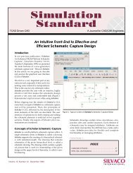
TCAD Driven CAD A Journal for Circuit Simulation and SPICE <strong>Modeling</strong> Engineers<br />
Abstract<br />
A novel extraction method of high frequency<br />
small-signal model parameters for MOSFET<br />
is proposed. From S-parameter measurement,<br />
this technique accurately extracts the MOSFET<br />
model parameters including the charge<br />
conservation capacitance parameters. To<br />
consider charge conservation, nonreciprocal<br />
capacitance is considered. The modeled<br />
S-parameters fit the measured ones well<br />
without any optimization after parameter<br />
extraction.<br />
I. Introduction<br />
As the gate-length of MOSFET reduces, its<br />
high frequency characteristics improve<br />
[1][2]. MOSFET is good candidate for RF IC application<br />
because of low cost, high integration and one-chip<br />
solution possibility for analog and digital circuits. The<br />
extraction of small-signal equivalent circuit parameters is<br />
important for the development of accurate large signal<br />
model. Recently, many suggestions have been made to<br />
improve the prediction of AC properties at high frequencies.<br />
Simple modifications to the conventional MOSFET<br />
equivalent circuit and a few methods of extracting<br />
small-signal equivalent circuit parameters have been reported<br />
[3]-[5]. However these are based on the MESFET model<br />
and require complex curve fitting and optimization.<br />
They also do not consider charge conservation<br />
capacitance parameters which are important in intrinsic<br />
capacitance modeling. Previous small-signal equivalent<br />
circuit models that do not consider charge conservation<br />
cannot accurately model the intrinsic capacitance.<br />
Volume 11, Number 1, January 2000<br />
RF CMOS Device <strong>Modeling</strong> :<br />
BSIM-Based Physical Model with<br />
Root-Like Construction Approach<br />
- <strong>Small</strong> <strong>Signal</strong> <strong>Modeling</strong> -<br />
Ickjin Kwon, Minkyu Je, Kwyro Lee, and Hyungcheol Shin<br />
Department of Electrical Engineering, Korea Advanced Institute of Science and Technology<br />
GATE<br />
R g<br />
dg<br />
C gd / C dg<br />
C gs<br />
∆Qg<br />
Cgs<br />
= ,<br />
∆V<br />
gs<br />
∆Qg<br />
Cgd<br />
=<br />
∆Vgd<br />
∆Qd<br />
Cdg<br />
= ,<br />
∆V<br />
∆Qd<br />
Cds<br />
=<br />
∆V<br />
BSIM3v3 model has been recognized as an accurate and<br />
scalable Si MOSFET model at the low frequency range,<br />
however the parameter extraction procedure for high<br />
frequencies has not been established yet. In particular,<br />
submicron MOSFET capacitances are difficult to extract in<br />
the MHz frequency rangne and the numerical optimization<br />
process may fail to obtain the physical parameter. The<br />
determination of the model capacitances, based on<br />
large area C-V test structure measurement proved to be<br />
inaccurate in the high frequency range [8].<br />
Continued on page 2....<br />
g m g ds Cds<br />
ds<br />
SOURCE = BODY<br />
INSIDE<br />
DRAIN<br />
VBIC Version 1.2 Released in SmartSpice<br />
and UTMOST III . . . . . . . . . . . . . . . . . . . . . . . . . . . . . 6<br />
Calendar of Events . . . . . . . . . . . . . . . . . . . . . . . . . . . . . 9<br />
Hints, Tips, and Solutions . . . . . . . . . . . . . . . . . . . . . . . . 10<br />
C jd<br />
R subd<br />
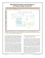
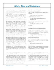
Figure 1. The proposed common-source equivalent circuit of a MOSFET after deembedding<br />
parasitics of on-wafer pads and interconnection lines. Four independent<br />
intrinsic capacitances Cgs, Cgd, Cdg, and Cds are needed for charge conservation.<br />
The definitions of each capacitance are also shown.<br />
SILVACO<br />
INTERNATIONAL
In this paper, we have developed a systematic parameter<br />
extraction method for MOSFET which includes charge<br />
conservation capacitance parameters, from measured<br />
S-parameters, and verified the results match well with<br />
measured data.<br />
II. New Extraction Method of<br />
<strong>Small</strong>-<strong>Signal</strong> Parameters<br />
The proposed common-source equivalent circuit of a<br />
MOSFET after de-embedding parasitics of on-wafer<br />
pads and interconnection lines is shown in Figure 1. The<br />
circuit elements between the substrate and source are<br />
excluded because the substrate is short-circuited to the<br />
source as in most high-frequency application. In this<br />
case, the substrate resistance that exists between the<br />
source and substrate is negligible. The proposed equivalent<br />
circuit is basically scalable since all its element are<br />
physically meaningful. The gate resistance Rg represents<br />
the effective channel resistance which consists of the<br />
distributed channel resistance seen from the gate and<br />
the distributed gate electrode resistance [9], which affect<br />
the input admittance Y11 at RF. The drain junction<br />
capacitance and the bulk spreading resistance are<br />
represented by Cjd and Rsubd. Substrate coupling<br />
effects through the drain junction and the substrate<br />
resistance play an important role for the output<br />
admittance Y22 [6].<br />
In the source-body tied three terminal structure, four<br />
independent intrinsic capacitances Cgs, Cgd, Cdg, and<br />
Cds are needed for charge conservation. The definitions<br />
of each capacitance are shown in Figure 1. The gate current<br />
Ig and the drain current Id and their associated charges<br />
Qg and Qd are related by the following equations.<br />
dQg<br />
ƒQg<br />
dVgs<br />
ƒQg<br />
dVgd<br />
ig<br />
= = +<br />
(1)<br />
dt ƒV<br />
dt ƒV<br />
dt<br />
= C<br />
gs<br />
gs<br />
dVgs<br />
+ C<br />
dt<br />
gd<br />
dV<br />
dt<br />
We have written Cdg and Cgd separately in the above<br />
equations, and Cdg is not equal to Cgd because of the<br />
difference in the signal excitation direction. These nonreciprocal<br />
capacitances are necessary for charge conservation<br />
of small signal model [10]. In equivalent circuit of<br />
MOSFET shown in Figure 1, overlap capacitances are<br />
included in Cgs, Cgd, Cdg and intrinsic capacitances are<br />
obtained by de-embedding overlap capacitances. The<br />
new extraction procedure uses linear regression<br />
approach for the Y-parameters which are converted<br />
from measured S-parameters. The small-signal equivalent<br />
circuit shown in Figure 1 can be analyzed in terms<br />
of Y-parameters as follows,<br />
gd<br />
dQ dV<br />
d ƒQd<br />
dg ƒQd<br />
dVds<br />
id<br />
= = +<br />
(2)<br />
dt ƒV<br />
dt ƒV<br />
dt<br />
gd<br />
For operation frequencies up to 10GHz,<br />
ω2 (Cgs+Cgd) 2Rg2
R subd and C jd are obtained from linear regression of<br />
ω 2 / [Re[Y 22] - g ds - ω 2 C dg 2 Rg] vs. ω 2 using the following relation.<br />
2<br />
ω 2 1 (17)<br />
= ω R<br />
2<br />
subd +<br />
Re[ Y ] − g −ω<br />
C R<br />
C R<br />
22<br />
ds<br />
2<br />
dg<br />
Rsubd is determined from slope of ω2 /[Re[Y22 ] - gds - ω2 2 Cdg Rg]<br />
as a function of ω2 and Cjd is extracted from (18).<br />
C<br />
ds<br />
Finally, C ds is obtained from (19) as<br />
III. Parameter Extraction Results<br />
g<br />
jd<br />
2 2<br />
jd Rsubd<br />
The test devices are multi-fingered n-MOSFET’s of<br />
AMS 0.35 µm CMOS technologies having unit gate<br />
width of 5 µm. The parameter extraction has been<br />
performed for an n-MOSFET with 100 mm width having<br />
twenty-unit gate fingers. To remove pad parasitics,<br />
de-embedding technique was carried out by subtracting<br />
parasitics of open pad structure from measured device<br />
S-parameters.<br />
The small signal parameters including charge conservation<br />
capacitance parameters were extracted at V gs = 1 V and<br />
V ds = 2 V using Eq. (11)-(19). Transconductance g m of<br />
16.6 mS was obtained from y-intercept of Re[Y 21] versus<br />
ω 2 as shown in Figure 2(a) and conductance g ds of 0.31<br />
mS was obtained from intercept of Re[Y 22] versus ω 2 , as<br />
shown in Figure 2(b). R subd of 200 Ω was determined<br />
from slope of ω 2 /[Re[Y 22] - g ds - ω 2 C dg 2 Rg] as a function<br />
of ω 2 as shown in Figure 3.<br />
The frequency dependence of extracted small-signal<br />
capacitance parameters for the n-MOSFET biased to<br />
V gs = 1 V and V ds = 2 V are shown in Figure 4. Also,<br />
extracted gate resistance R g as a function of frequency<br />
for the n-MOSFET biased to V gs = 1 V and V ds = 2V is<br />
Re(Y21) [mS]<br />
2<br />
jd<br />
subd<br />
C<br />
= Im[ Y22<br />
] / ω −C<br />
dg −<br />
(19)<br />
2<br />
1+<br />
ω C<br />
17<br />
16<br />
15<br />
14<br />
g m = 16.6 mS<br />
W / L = 100 / 0.35<br />
V gs = 1 V, V ds = 2 V<br />
13<br />
0.0 0.5 1.0 1.5 2.0 2.5 3.0<br />
ω 2 [ x10 21 rad 2 ]<br />
(a)<br />
0 1 2 3 4 5<br />
shown in Figure 5. The frequency range is from<br />
0.5 GHz to 10.5 GHz. The results shows that extracted<br />
parameters remains almost constant with frequency.<br />
Figure 4 and Figure 5 verified that this extraction<br />
method is accurate and reliable.<br />
For the extracted parameter values, ω 2 (C gs + C gd) 2 R g 2 is<br />
calculated to be 0.06 at 10 GHz, which is much smaller<br />
than one. This verifies the validity of using the assumption<br />
in simplifying Eq. (3) – Eq. (6) to Eq. (7) – Eq. (10).<br />
Figure 6 shows measured and modeled Y-parameters<br />
using extracted model parameters and the small signal<br />
equivalent circuit shown in Figure 1. It shows that the<br />
modeled S-parameter fit the measured ones well<br />
without any optimization after parameter extraction.<br />
January 2000 Page 3 The Simulation Standard<br />
ω 2 / [Re(Y 22 )-g ds-ω 2 C dg 2 R g ] [ x10 24 ]<br />
1.5<br />
1.0<br />
0.5<br />
W / L = 100 / 0.35<br />
V gs = 1 V, V ds = 2 V<br />
slope : R subd = 200 Ω<br />
ω 2 [ x10 21<br />
rad 2 ]<br />
Fig. 3. Rsubd was determined from the slope of w2 / [Re[Y22] -<br />
gds - w2Cdg2Rg] as a function of w2. Extracted value of<br />
Rsubd was 200 W.<br />
0.2<br />
gds = 0.31 mS<br />
0.0<br />
0.0 0.1 0.2 0.3 0.4 0.5 0.6<br />
ω 2 [ x10 21 rad 2 ]<br />
Fig. 2. Extraction of conductance gm and gds. (a) gm was obtained from y-intercept of Re[Y21] versus w2 . Extracted value of gm was<br />
16.6 mS. (b) gds was obtained from y-intercept of Re[Y22] versus w2 . Extracted value of gds was 0.31 mS.<br />
Re(Y22) [mS]<br />
1.2<br />
1.0<br />
0.8<br />
0.6<br />
0.4<br />
W / L = 100 / 0.35<br />
V gs = 1 V, V ds = 2 V<br />
(b)
Capacitance [fF]<br />
160<br />
140<br />
120<br />
100<br />
80<br />
60<br />
40<br />
20<br />
0<br />
W / L = 100 / 0.35<br />
V gs = 1 V, V ds = 2 V<br />
Cdg Cgd 0 2 4 6 8 10 12<br />
Frequency [GHz]<br />
Figure 4. The frequency dependence of extracted capacitance<br />
parameters for an n-MOSFET having 100 mm width and biased<br />
to Vgs = 1 V and Vds = 2 V. Extracted parameters remain<br />
almost constant with frequency.<br />
The admittance Y 11 fits the measured data well with<br />
gate resistance model and Y 22 fits well with substrate<br />
resistance model. The non-reciprocal capacitance C gd<br />
and C dg contribute to match imaginary part of Y 12 and Y 21.<br />
Y11 [mS]<br />
Y21 [mS]<br />
12<br />
10<br />
8<br />
6<br />
4<br />
2<br />
0<br />
0 2 4 6 8 10<br />
Frequency [GHz]<br />
20<br />
10<br />
0<br />
Measured<br />
Proposed Model<br />
W / L = 100 / 0.35<br />
V gs = 1 V, V ds = 2 V<br />
(a)<br />
Measured<br />
Proposed Model<br />
Imag<br />
Real<br />
-10<br />
W / L = 100 / 0.35<br />
V = 1 V, V = 2V<br />
gs ds<br />
Imag<br />
-20<br />
0 2 4 6 8 10<br />
Frequency [GHz]<br />
(c)<br />
Real<br />
C gs<br />
C jd<br />
C ds<br />
0<br />
0 2 4 6 8 10<br />
Frequency [GHz]<br />
Figure 5. The frequency dependence of gate resistance Rg for<br />
an n-MOSFET having 100 mm width and biased to Vgs = 1 V<br />
and Vds = 2 V. Gate resistance Rg remains almost constant<br />
with frequency.<br />
In Figure 7, gate-bias dependence of the extracted<br />
small-signal parameters for the n-MOSFET biased to<br />
Vds = 2 V is shown. In Fig. 7(a), Cgs increases gradually<br />
as gate bias increases in the saturation region and drops<br />
in the linear region. Since the intrinsic gate-drain capac-<br />
The Simulation Standard Page 4 January 2000<br />
R g [ Ω ]<br />
70<br />
60<br />
50<br />
40<br />
30<br />
20<br />
10<br />
W / L = 100 / 0.35<br />
V gs = 1 V, V ds = 2 V<br />
-2.5 W / L = 100 / 0.35<br />
Imag<br />
-3.0<br />
0<br />
Vgs = 1 V, Vds = 2 V<br />
2 4 6 8 10<br />
Figure 6. The measured and modeled Y-parameters using extracted model parameters for the n-MOSFET biased to Vgs = 1 V and Vds<br />
= 2 V. The frequency range is from 0.5 GHz to 10.5 GHz. (a)Y11 (b)Y12 (c)Y21 (d)Y22. It shows that the modeled S-parameters fit the<br />
measured ones well without any optimization after parameter extraction.<br />
Y12 [mS]<br />
Y22 [mS]<br />
0.0<br />
-0.5<br />
-1.0<br />
-1.5<br />
-2.0<br />
6<br />
4<br />
2<br />
Measured<br />
Proposed Model<br />
Frequency [GHz]<br />
(b)<br />
Measured<br />
Proposed Model<br />
W / L = 100 / 0.35<br />
V gs = 1 V, V ds = 2 V<br />
Real<br />
Imag<br />
Real<br />
0<br />
0 2 4 6 8 10<br />
Frequency [GHz]<br />
(d)
Capacitance [fF]<br />
160<br />
140<br />
120<br />
100<br />
80<br />
60<br />
40<br />
20<br />
0<br />
W / L = 100 / 0.35<br />
V ds = 2 V<br />
1 2 3 4<br />
V [ V ] gs<br />
Fig. 7. The gate-bias dependence of extracted parameters for an n-MOSFET having 100 mm width and biased to Vds = 2 V. (a)<br />
Capacitances (b) Conductances and resistances.<br />
itance is small compared to overlap capacitance in the<br />
saturation region, Cgd and Cdg are almost constant in<br />
the saturation region and increase gradually in the linear<br />
region. The smooth behaviors for Cgs, Cgd and Cdg<br />
are because the region-to-region transition is very gradual<br />
due to short-channel effects. Fig. 7(b) shows that<br />
transconductance gm increases as gate bias increases<br />
for small Vgs and gm decreases for high gate bias due<br />
to mobility degradation. Drain conductance gds<br />
increases almost proportional to gate bias in the saturation<br />
region due to short channel effects and gds rapidly<br />
increases with Vgs in the linear region because for higher<br />
gate bias drain current increases more rapidly with<br />
drain bias in the linear region.<br />
IV. Conclusions<br />
A novel extraction method of obtaining an accurate<br />
high frequency small-signal parameters for MOSFET<br />
has been demonstrated. The nonreciprocal capacitance<br />
was introduced and this technique accurately extracted<br />
the charge conservation capacitance parameters. The<br />
proposed model from parameter extraction has been<br />
evaluated with measured S-parameter and good agreement<br />
has been observed. Developed extraction method<br />
is an effective parameter extraction technique for the<br />
large-signal BSIM3v3 model.<br />
(a)<br />
C gs<br />
C jd<br />
C dg<br />
C gd<br />
C ds<br />
References<br />
0<br />
1 2 3 4<br />
[1] C. Wann, L. Su, K. Jenkins, R. Chang, D. Frank, Y. Taur, "RF<br />
Perspective of Sub-Tenth-Micron CMOS," IEEE International Solid-<br />
State Circuits Conference, pp. 254-255, 1998.<br />
[2] E. Morifuji, et al., Future perspective and scaling down roadmap for<br />
RF CMOS, Symposium on VLSI Technology Digest of Technical<br />
Papers, pp. 163-164, 1999.<br />
[3] D. Lovelace, J. Costa, N. Camilleri, "Extracting <strong>Small</strong>-<strong>Signal</strong> Model<br />
Parameters of Silicon MOSFET Transistors", IEEE MTT-S Digest,<br />
1994, pp.865-868.<br />
[4] G. D. Dambrine, A. Cappy, F. Helidore, and E. Palyze, "A new<br />
method for determining the FET small-signal equivalent circuit."<br />
IEEE Trans. Microwave Theory Tech., vol. 36, pp. 173-176, 1998.<br />
[5] S. Lee, H. K. Yu, C. S. Kim, J. G. Koo, and K. S. Nam, "A novel<br />
approach to extracting small-signal model parameters of silicon<br />
MOSFET’s," IEEE Microwave and guided wave letters, vol. 7, pp.<br />
75-77, 1997.<br />
[6] W. Liu, R. Gharpurey, M. C. Chang, U. Erdogan, R. Aggarwal, and<br />
J. P. Mattia, "RF MOSFET modeling accounting for distributed substrate<br />
and channel resistance with emphasis on the BSIM3v3<br />
SPICE model," in IEDM Tech. Dig., pp.309-312, Dec. 1997.<br />
[7] J. J. Ou, X. Jin, I. Ma, C. Hu, "CMOS RF modeling for GHz communication<br />
IC’s," VLSI Symp. On Tech., Dig. of Tech. Papers, pp. 94-<br />
95, June 1998.<br />
[8] D. R. Pehlke, M. Schroder, A. Burstein, M. Matloubian, M. F. Chang,<br />
"High frequency application of MOS compact model and their<br />
development for scalable RF model libraries," Proc. of CICC, pp.<br />
219-222, May 1998.<br />
[9] X. Jin, J. J. Ou, C-H C, W. Liu, J. Deen, P. R. Gray, C. Hu, "An<br />
Effective Gate Resistance Model for CMOS RF and Noise modeling,"<br />
in IEDM Tech. Dig., 1998.<br />
[10] Ping Yang, Berton D. Epler, Pallab K. Chatterjee, "An Investigation<br />
of the Charge conservation Problem for MOSFET Circuit<br />
Simulation", IEEE Journal of Solid-State Circuits, vol. Sc-18, no. 1.<br />
Feb, 1983.<br />
January 2000 Page 5 The Simulation Standard<br />
Conductance [mS]<br />
30<br />
25<br />
20<br />
15<br />
10<br />
5<br />
0<br />
g m<br />
g ds<br />
W / L = 100 / 0.35<br />
V ds = 2 V<br />
V gs [ V ]<br />
(b)<br />
R subd<br />
R g<br />
250<br />
200<br />
150<br />
100<br />
50<br />
Resistance [ Ω ]
VBIC Version 1.2 Released in SmartSpice and UTMOST III<br />
Introduction<br />
The latest VBIC bipolar model v1.2 of Sep 24 1999 has<br />
been integrated into SmartSpice and UTMOST III. It can<br />
be invoked by specifying the model selector LEVEL=5<br />
and the version selector VERSION=1.2. in the .MODEL<br />
card. This new version becomes the default VBIC model.<br />
A new model parameter REVISION has been introduced<br />
to invoke future updates or older VBIC models. In<br />
SmartSpice/UTMOST III, only the old version 1.1.5 is still<br />
supported and can be invoked by specifying VERSION=1.1<br />
and REVISION=5. If other values are given, v1.2 is<br />
assumed. Aliases are listed in Table 1.<br />
The explicit specification of VERSION and REVISION is<br />
strongly recommended to avoid incompatibility problems<br />
between v1.1.5 and v1.2.<br />
New Features in VBIC v1.2:<br />
Here is a summary list of major updates and enhancements<br />
announced in v1.2 and relative to v1.1.5:<br />
l temperature dependence of IKF,<br />
l separate temperature coefficients for intrinsic and<br />
extrinsic resistances RCX, RBX and RBP,<br />
l simple exponential base-emitter breakdown model,<br />
l reach-through model to limit base-collector depletion<br />
capacitances,<br />
l separate activation energy for ISP,<br />
l selector available to switch to SGP qb formulation,<br />
l high-current roll-off coefficient,<br />
l fixed collector-substrate capacitance,<br />
l separate IS allowed for reverse operation in HBTs,<br />
l error fixed in the built-in potential temperature<br />
mapping (psibi function).<br />
All these new features have been implemented in<br />
SmartSpice. Only the 3-terminal version of the model<br />
described in the official release is not currently<br />
supported. Due to some of these changes, VBICv1.2 is<br />
not fully backward compatible with the previous version<br />
(1.1.5).<br />
New Model Parameters in VBICv1.2:<br />
All parameters supported in v1.1.5 are still used in v1.2.<br />
However, the definition has slightly changed for the<br />
following ones:<br />
Due to the separation of the temperature dependence<br />
for intrinsic and extrinsic resistances, XRC and XRB now<br />
correspond to XRCI and XRBI, respectively. Aliases<br />
XRCI and XRBI have been added for convenience.<br />
Due to changes in the formulation of the single piece<br />
depletion capacitance model, the smoothing factors<br />
AJE, AJC, AJS are now expressed in volts.<br />
VBICv1.2 has 19 new model parameters that are shown<br />
in Table 2.<br />
New Temperature Mappings<br />
The following abbreviations are defined for convenience:<br />
where TNOM is the temperature at which model parameter<br />
extraction has been done. T d corre-sponds to the<br />
dynamic temperature if self-heating is turned on or to<br />
the operating temperature otherwise.<br />
l A bug in psibi mapping with temperature has been<br />
fixed. The psibi function is used to calculate built-in<br />
potentials PE, PC and PS at the device temperature<br />
as a function of related model parameters and<br />
activation energies EAIE, EAIC and EAIS, respectively.<br />
The updated expressions are (actually, only the<br />
expression pssio has been corrected):<br />
Parameter (alias) Description Units Default<br />
VERSION (VERS) Version parameter. Only 1.1 (if REV=5) and - 1.2<br />
1.2 (if REV= 0) are permitted, otherwise 1.2 is assumed.<br />
REVISION (REV, VREV) Revision parameter. Only 0 (if VERS=1.2) and 5 - 0<br />
(if VERS=1.1) are permitted, otherwise 0 is assumed.<br />
Table 1.<br />
k ⋅ T<br />
d<br />
k ⋅ TNOM<br />
T<br />
d<br />
V<br />
td<br />
= ------------ , V and<br />
q tnom<br />
= ------------------------ r<br />
q td<br />
= ----------------<br />
TNOM<br />
psiio ( P)<br />
2.0 V ⎛ P<br />
tnom<br />
---------------------------- ⎞<br />
P<br />
= ⋅ ⋅ log ⎛exp – exp⎛–<br />
----------------------------⎞⎞<br />
⎝ ⎝2.0 ⋅ V ⎠ ⎝<br />
tnom<br />
2.0 ⋅ V ⎠⎠<br />
tnom<br />
psiin( P, Ea, T<br />
d<br />
) = psiio ⋅ r<br />
td<br />
– 3.0 ⋅ V<br />
td<br />
⋅ log(<br />
r<br />
td<br />
) – Ea ⋅ ( r<br />
td<br />
– 1.0)<br />
⎛ psiin<br />
psibi( P, Ea, T<br />
d<br />
) psiin 2.0 V<br />
td<br />
1.0 1.0 4.0 ⎛<br />
⎝<br />
– ------------ ⎞<br />
⎞<br />
=<br />
+ ⋅ ⋅log<br />
⎜ + + ⋅ exp<br />
⎝ V ⎠<br />
⎟ ⁄ 2.0<br />
td ⎠<br />
The Simulation Standard Page 6 January 2000
Parameter (alias) Description Units Default<br />
XRBX Temperature exponent of extrinsic resistance RBX - 0.0<br />
XRCX Temperature exponent of extrinsic resistance RCX - 0.0<br />
XRBP Temperature exponent of extrinsic resistance RBP - 0.0<br />
XIKF Temperature exponent of IKF - 0.0<br />
ISRR Reverse saturation current factor (HBTs) - 1.0<br />
XISR Temperature exponent of ISRR (HBTs) - 0.0<br />
DEAR Activation energy shift for ISRR (HBTs) V 0.0<br />
EAP Activation energy for ISP V 1.12<br />
VBBE Base-Emitter breakdown voltage, zero means infinity V 0.0<br />
TVBBE1 First temperature coefficient of VBBE 0.0<br />
TVBBE2 Second temperature coefficient of VBBE 0.0<br />
NBBE Base-Emitter breakdown emission coefficient - 1.0<br />
TNBBE Temperature coefficient of NBBE 0.0<br />
IBBE Base-Emitter breakdown current A 1.0e-6<br />
QBM Selector for SGP qb formulation - 0.0<br />
NKF High current roll-off coefficient - 0.5<br />
VRT B-C reach-through limiting voltage (0 means infinity) V 0.0<br />
ART B-C reach-through limiting smoothing factor V 0.1<br />
CCSO Fixed collector-substrate capacitance F 0.0<br />
Table 2.<br />
l Some equations have been updated according to<br />
new model parameters:<br />
RCX( T<br />
d<br />
) RCX ( r<br />
td<br />
) XRCX<br />
= ⋅<br />
RBX( T<br />
d<br />
) RBX ( r<br />
td<br />
) XRBX<br />
= ⋅<br />
RBP( T<br />
d<br />
) RBP ( r<br />
td<br />
) XRBP<br />
= ⋅<br />
XIS<br />
-----------<br />
NFP ⎛ EAP<br />
1.0 – r<br />
td⎞<br />
ISP( T<br />
d<br />
) = ISP ⋅ ( r<br />
td<br />
) ⋅ exp⎜–<br />
----------- ⋅ -------------------- ⎟<br />
⎝ NFP V<br />
td ⎠<br />
l New equations have been added:<br />
IKF( T<br />
d<br />
) IKF ( r<br />
td<br />
) XIKF<br />
= ⋅<br />
(new paramerter XRCX)<br />
(new paramerter XRBX)<br />
(new paramerter XRBP)<br />
(new paramerter EAP)<br />
XISR<br />
------------<br />
NR ⎛ DEAR<br />
1.0 – r<br />
td⎞<br />
ISRR( T<br />
d<br />
) = ISRR ⋅ ( r<br />
td<br />
) ⋅ exp⎜–<br />
--------------- ⋅ -------------------- ⎟<br />
⎝ NR V<br />
td ⎠<br />
(new parameters ISSR, XISR, DEAR)<br />
VBBE( T<br />
d<br />
) VBBE 1.0 TVBBE1 ⋅ ( T<br />
d<br />
– TNOM)<br />
TVBBE2 ( T<br />
d<br />
– TNOM)<br />
2<br />
= ⋅ ( + + ⋅<br />
)<br />
(new parameters ISSR, XISR, DEAR)<br />
NBBE( T<br />
d<br />
) = NBBE ⋅ ( 1.0 + TNBBE ⋅ ( T<br />
d<br />
– TNOM)<br />
)<br />
(new parameters VBBE, TVBBE1, TVBBE2)<br />
EBBE( T<br />
d<br />
)<br />
⎛ VBBE( T<br />
d<br />
) ⎞<br />
= exp⎜–<br />
---------------------------------------- ⎟<br />
⎝ NBBE( T<br />
d<br />
) ⋅ V<br />
td⎠<br />
(new parameter XIKF)<br />
New Current Equations<br />
l The equation of the ideal reverse current has been<br />
modified to account for a separate saturation current<br />
IS in reverse operation (HBTs). However backward<br />
compatibility is maintained if new model parameters<br />
ISSR, XISR and DEAR are unspecified (default values<br />
lead to). The new equation is:<br />
Vbci<br />
Itri = IS( T<br />
d<br />
) ⋅ISSR( T<br />
d<br />
) ⋅ ⎛exp⎛-------------------- ⎞ – 1.0⎞<br />
⎝ ⎝NR ⋅ Vtd⎠<br />
⎠<br />
l Two expressions for the base charge equation are<br />
now available and can be selected using the model<br />
parameter QBM. The standard Gummel-Poon formulation<br />
has been introduced. The high-current<br />
roll-off coefficient NKF is also supported. If NKF is<br />
unspecified, its default value is equal to 0.5 and the<br />
first expression reduces to qb 0. 5 q1 q1<br />
for back-ward compatibility with v1.1.5.<br />
2 =<br />
⋅ + + 4⋅q2 if (QBM
l If VBBE > 0.0, a new contribution is added to intrinsic<br />
and extrinsic base-emitter currents Ibe and Ibex<br />
to account for the B-E breakdown effect:<br />
Vbei<br />
Ibe i = IBE I⋅<br />
⎛ ⎛<br />
⎝<br />
-----------------------⎞<br />
⎝<br />
exp<br />
NE I ⋅ Vtd⎠<br />
– 1.0⎞<br />
⎠<br />
Vbei<br />
Iben = IBEN⋅<br />
⎛exp ⎛ -------------------------⎞–<br />
1. 0⎞<br />
⎝ ⎝NEN ⋅Vtd<br />
⎠ ⎠<br />
⎛ ⎛– VBBE ( T<br />
d<br />
) – Vbei⎞ ⎞<br />
Ibebk = IBEE ⋅⎜exp<br />
⎜------------------------------------------------- ⎟–<br />
EBBE ( T<br />
⎝ NBBE ( T<br />
d<br />
) ⋅ Vtd ⎠<br />
d<br />
) ⎟<br />
⎝ ⎠<br />
Ibe = WBE ⋅ [ Ibei + Iben – Ibebk ]<br />
Vbex<br />
Ibex i = IBEI ⋅ ⎛ ⎛<br />
⎝<br />
-----------------------⎞<br />
⎝<br />
exp<br />
NEI ⋅Vtd<br />
⎠<br />
– 1. 0⎞<br />
⎠<br />
Vbex<br />
Ibexn = IBEN ⋅ ⎛exp ⎛ -------------------------⎞<br />
⎝NEN⋅ Vtd ⎠<br />
– 1. 0⎞<br />
⎝ ⎠<br />
Ib exb k = IBEE<br />
⎛ ⎛– VBBE ( T<br />
d<br />
) – Vbex⎞<br />
⎞<br />
⋅⎜exp⎜--------------------------------------------------<br />
⎟–<br />
EBBE ( T<br />
⎝ NBBE ( T<br />
d<br />
) ⋅V<br />
td ⎠<br />
d<br />
) ⎟<br />
⎝ ⎠<br />
Ibex = ( 1. 0 – WBE)<br />
⋅ [ Ib ex i + Ibex n – Ib exbk ]<br />
New Charge Equations<br />
l A new depletion capacitance model with optional<br />
reach-through limiting has been introduced to evaluate<br />
normalized depletion charges qdbc and qdbep<br />
(other depletion charges are still evaluated using the<br />
function qj). Assuming that V is the junction applied<br />
voltage, P is the junction built-in potential, FC is the<br />
forward bias depletion capacitance limit, M is the<br />
junc-tion grading coefficient and AJ is the smoothing<br />
factor, the new function qjrt is defined by:<br />
AJ≤ 0<br />
dvh = V – FC⋅ P<br />
dvh> 0.0<br />
1.0 1.0 FC<br />
qj P –<br />
1.0 M<br />
( ) –<br />
dvh M<br />
1. 0 FC<br />
–<br />
⋅ ------------------------------------------------------ dvh<br />
1. 0 – M<br />
⋅<br />
– + ------------------<br />
2.0 ⋅ P<br />
1.0 M<br />
( 1.0 – FC ) +<br />
If<br />
Define<br />
If (large forward bias)<br />
=<br />
+ ⋅ --------------------------------- ---<br />
else if VRT > 0.0 and V< – VRT<br />
qj<br />
--- -------<br />
P<br />
-----------------------<br />
1.0 –<br />
1.0 1.0<br />
M<br />
VRT 1.0 M<br />
⎛ +<br />
⎝<br />
----------<br />
⎞<br />
P ⎠<br />
–<br />
(new equation for large reverse bias)<br />
=<br />
( 1. 0– M ) ⋅(<br />
V+ VRT<br />
⋅⎛<br />
–<br />
⋅ 1.0 – ----------------------------------------------------- ) ⎞<br />
⎝<br />
( P + VRT ) ⎠<br />
else (medium forward and reverse bias)<br />
1.0 1.0<br />
qj P<br />
V 1.0 M<br />
⎛ – -- ⎞<br />
⎝ P⎠<br />
–<br />
–<br />
= ⋅ ---------------------------------------------------<br />
1.0 – M<br />
else (single piece model)<br />
If VRT > 0.0 and ART > 0.0 (new parameters VRT and ART)<br />
Define dv0 = – FC ⋅ P<br />
VRT + dv0<br />
vn0 = --------------------------<br />
VRT – dv0<br />
(NEW)<br />
2 ⋅ vn0<br />
vnl0<br />
( vn0 – 1.0)<br />
2<br />
4 AJ 2<br />
+ ⋅ ( vn0 + 1.0)<br />
2<br />
4 ART 2<br />
= ------------------------------------------------------------------------------------------------------------------------------<br />
+<br />
+ ⋅<br />
l0 = 0.5⋅( vnl0 ⋅ ( VRT – dv0)<br />
– VRT – dv0)<br />
vl0 1.0 M<br />
1.0 ⎛<br />
⎝<br />
1.0 – ------- ⎞<br />
P ⎠<br />
qlo0 P<br />
–<br />
–<br />
= ⋅ -------------------------------------------------------<br />
1.0 – M<br />
2.0 ⋅ V + VRT + dv0<br />
vn = ------------------------------------------------<br />
VRT – dv0<br />
2 ⋅ vn<br />
vnl<br />
( vn – 1.0)<br />
2<br />
4 AJ 2<br />
+ ⋅ ( vn + 1.0)<br />
2<br />
4 ART 2<br />
= -----------------------------------------------------------------------------------------------------------------------<br />
+<br />
+ ⋅<br />
vl = 0.5 ⋅ ( vnl ⋅ ( VRT – dv0)<br />
– VRT – dv0)<br />
vl 1.0 M<br />
1.0 ⎛<br />
⎝<br />
1.0 – --- ⎞<br />
P⎠<br />
qlo P<br />
–<br />
–<br />
= ⋅ ----------------------------------------------------<br />
1.0 – M<br />
sel = 0.5 ⋅ ( vnl + 1.0)<br />
crt 1.0 VRT ⎛<br />
⎝<br />
+ ---------- ⎞<br />
P ⎠<br />
M –<br />
=<br />
cmx ( 1.0 – FC)<br />
M –<br />
=<br />
cl = ( 1.0 – sel)<br />
⋅ crt + sel ⋅ cmx<br />
ql = ( V – vl + vl0)<br />
⋅ cl<br />
qjrt = ql + qlo – qlo0<br />
else (no reach-through limiting)<br />
vl 0.5 V– FC⋅P ( V– FC ⋅ P)<br />
2<br />
4 AJ 2<br />
= ⋅ ⎛<br />
⎝<br />
–<br />
+ ⋅ ⎞<br />
⎠<br />
+ FC ⋅ P<br />
vl0 0.5 – FC ⋅ P ( – FC ⋅ P)<br />
2<br />
4 AJ 2<br />
= ⋅ ⎛<br />
⎝<br />
–<br />
+ ⋅ ⎞<br />
⎠<br />
+ FC ⋅ P<br />
vl 1.0 M<br />
⎛1.0 – --- ⎞<br />
⎝ P⎠<br />
qj – P<br />
–<br />
V– vl+ vl0<br />
⋅ --------------------------------------<br />
1.0 – M<br />
( 1.0 – FC)<br />
M<br />
vl0 1.0 M<br />
⎛<br />
⎝<br />
1.0 – ------- ⎞<br />
P ⎠<br />
----------------------------- P<br />
–<br />
=<br />
+ + ⋅ ------------------------------------------<br />
1.0 – M<br />
It is important to notice that qj and qjrt functions are<br />
identical if VRT is set to zero (no reach- through limiting).<br />
The influence of the reach-through limiting on normalized<br />
depletion capacitances only occurs for reverse biased<br />
junction as shown on Figure 1 and Figure 2. Figure 1<br />
corresponds to the SGP-like model, where the depletion<br />
capacitance linearly increases for values of forward bias<br />
greater than FC.P. Figure 2 corresponds to the single<br />
piece model where the depletion capacitance smootly<br />
limits to its value at FC.P. The effect of reach-through<br />
limiting is similar for both models.<br />
Continued on page 11....<br />
The Simulation Standard Page 8 January 2000
January<br />
1 New Years Day<br />
2<br />
3<br />
4<br />
5<br />
6<br />
7<br />
8<br />
9<br />
10<br />
11<br />
12<br />
13<br />
14<br />
15<br />
16<br />
17<br />
18<br />
19<br />
20<br />
21<br />
22<br />
23<br />
24<br />
25<br />
26<br />
27 EDA TechnoFair,<br />
Yokohama, Japan<br />
28 EDA TechnoFair,<br />
Yokohama, Japan<br />
29<br />
30<br />
31<br />
Calendar of Events<br />
1<br />
2<br />
3<br />
4<br />
5<br />
6<br />
7<br />
8<br />
9<br />
10<br />
11<br />
12<br />
13<br />
14<br />
15<br />
16<br />
17<br />
18<br />
19<br />
20<br />
21<br />
22<br />
23<br />
24<br />
25<br />
26<br />
27<br />
28<br />
29<br />
February<br />
For more information on any of our workshops, please check our web site at http://www.silvaco.com<br />
Bulletin Board<br />
EDA Techofair<br />
The premier EDA tradeshow in Japan will be<br />
anchored once again by the presence of <strong>Silvaco</strong><br />
International. With major staffing from our Japan<br />
office and corporate headquarters in the U.S.,<br />
plus nine workstations to demonstrate our tools,<br />
be prepared to understand why we are the<br />
emerging EDA leader.<br />
10 Years of Publication<br />
Simulation Standard has just completed its<br />
tenth year of publication! Since 1990, <strong>Silvaco</strong><br />
has delivered this valuable tool to our constituents.<br />
The first issue debuted under the title<br />
"The Exterminator" in May 1990. In June 1992,<br />
Simulation Standard was sent out for the first<br />
time. Currently, our newsletter reaches tens of<br />
thousands of designers worldwide. Thank you<br />
for making it a success!<br />
Another Record Tradeshow Year<br />
The year 2000 will set another record for<br />
tradeshow exhibitions by <strong>Silvaco</strong>. After meeting<br />
many of you at our thirty-three tradeshows in<br />
1999, we are embarking on an aggressive schedule<br />
of over forty shows for 2000. To execute this<br />
task, <strong>Silvaco</strong> has handed the tradeshow torch<br />
from David Warren to Mr. Ryan Melius as the<br />
new Tradeshow Marketing Manager.<br />
The Simulation Standard, circulation 18,000 Vol. 11, No. 1, January 2000 is copyrighted by <strong>Silvaco</strong> International. If you, or someone you know wants a subscription<br />
to this free publication, please call (408) 567-1000 (USA), (44) (1483) 401-800 (UK), (81)(45) 820-3000 (Japan), or your nearest <strong>Silvaco</strong> distributor.<br />
Simulation Standard, TCAD Driven CAD, Virtual Wafer Fab, Analog Alliance, Legacy, ATHENA, ATLAS, MERCURY, VICTORY, VYPER, ANALOG EXPRESS,<br />
RESILIENCE, DISCOVERY, CELEBRITY, Manufacturing Tools, Automation Tools, Interactive Tools, TonyPlot, TonyPlot3D, DeckBuild, DevEdit, DevEdit3D,<br />
Interpreter, ATHENA Interpreter, ATLAS Interpreter, Circuit Optimizer, MaskViews, PSTATS, SSuprem3, SSuprem4, Elite, Optolith, Flash, Silicides, MC<br />
Depo/Etch, MC Implant, S-Pisces, Blaze/Blaze3D, Device3D, TFT2D/3D, Ferro, SiGe, SiC, Laser, VCSELS, Quantum2D/3D, Luminous2D/3D, Giga2D/3D,<br />
MixedMode2D/3D, FastBlaze, FastLarge<strong>Signal</strong>, FastMixedMode, FastGiga, FastNoise, Mocasim, Spirt, Beacon, Frontier, Clarity, Zenith, Vision, Radiant,<br />
TwinSim, , UTMOST, UTMOST II, UTMOST III, UTMOST IV, PROMOST, SPAYN, UTMOST IV Measure, UTMOST IV Fit, UTMOST IV Spice <strong>Modeling</strong>,<br />
SmartStats, SDDL, SmartSpice, FastSpice, Twister, Blast, MixSim, SmartLib, TestChip, Promost-Rel, RelStats, RelLib, Harm, Ranger, Ranger3D Nomad, QUEST,<br />
EXACT, CLEVER, STELLAR, HIPEX-net, HIPEX-r, HIPEX-c, HIPEX-rc, HIPEX-crc, EM, Power, IR, SI, Timing, SN, Clock, Scholar, Expert, Savage, Scout,<br />
Dragon, Maverick, Guardian, Envoy, LISA, ExpertViews and SFLM are trademarks of <strong>Silvaco</strong> International.<br />
January 2000 Page 9 The Simulation Standard
Mustafa Taner, Applications and Support Engineer<br />
Q. How can I characterize the parasitic BJT behavior of<br />
SOI devices using UTMOST III.<br />
A. UTMOST III SOI module has three routines for<br />
characterization of the parasitic BJTs of SOI devices.<br />
These routines are "IC/VCE", "Gummel" and "INT_BJT"<br />
All routines require to have 5 terminal devices with<br />
bulk connection for data collection.<br />
The "Gummel" routine sweeps the voltage for the bulk<br />
terminal and keeps a constant voltage for the gate,<br />
source, drain and backgate terminals. The measured<br />
currents are drain and bulk currents. However during<br />
this measurement the bulk and drain diodes can be on<br />
and the diode current can be added to the bulk current.<br />
This additional diode current prevents the user from<br />
characterizing the pure intrinsic bipolar device.<br />
The "INT_BJT" routine was developed to exclude any<br />
additional diode currents which may contribute to the<br />
intrinsic bipolar behavior. In order to achieve this goal<br />
the source terminal bias was swept and bulk and drain<br />
terminals were kept at the same potential (typically at<br />
ground potential). The gate potential's effect on the<br />
parasitic bipolar behavior was also investigated.<br />
Therefore the VGS bias stepping function was added to<br />
the routine (Figure 1). In order to keep the VGS bias<br />
Hints, Tips and Solutions<br />
Figure 2. Idrain and Ibulk currents versus VSB voltage at three different VGS<br />
bias points.<br />
Figure 1. The Set measureemnt screen of the INT_BJT routine.<br />
constant the VG bias has to follow the sweeping bias of<br />
VS. The constant VGS bias is obtained by using the<br />
"offset" (VAR1') function of the DC analyzers HP4145<br />
and HP4155/56. The HP4142 DC analyzer uses the<br />
point by point (user mode) measurement technique to<br />
keep the constant VGS bias.<br />
The "INT_BJT" routine displays the measured<br />
drain and bulk currents versus VSB (source<br />
to bulk) voltage (Figure 2). The global and<br />
local optimization techniques can be utilized<br />
to extract parameters which are used to<br />
model the parasitic bipolar behavior in SOI<br />
devices. The important model parameters of<br />
the parasitic bipolar device in BSIM3v3 partially<br />
depleted SOI model are:<br />
ISBJT (BJT injection saturation current)<br />
NBJT (Power coefficient of channel length<br />
dependency for bipolar current)<br />
LBJT0 (Reference channel length for bipolar<br />
current)<br />
VABJT (Early voltage for bipolar current)<br />
AELY (Channel length dependency of early<br />
voltage for bipolar current)<br />
AHLI (High level injection parameter for<br />
bipolar current)<br />
The Simulation Standard Page 10 January 2000
Q. Can <strong>Silvaco</strong> provide a bipolar modeling service<br />
using the advanced bipolar models such as MEXTRAM<br />
and VBIC?<br />
A. Yes. Both MEXTRAM and VBIC models have been<br />
implemented in SmartSpice and UTMOST III. <strong>Silvaco</strong><br />
characterization lab provides the advanced bipolar<br />
modeling service using both models as well as<br />
Gummel-Poon and Macro models.<br />
The advanced bipolar models provide many advantages<br />
over the Gummel-Poon and Macro models. Some of the<br />
major advantages can be listed as:<br />
l Improved early effect modeling<br />
l Quasi-saturation modeling. (Both Gummel Poon<br />
(including level=2 GP model) and macro models can<br />
not model this behavior)<br />
l Parasitic substrate current modeling. (The Gummel-Poon<br />
...continued from page 8<br />
Figure 1. Figure 2.<br />
Another important point is that the qj function implemented<br />
in v1.1.5 has been slightly modified in v1.2. The<br />
smoothing factor AJ has been replaced by 4*AJ*AJ in vl<br />
and vl0 expressions.<br />
l The contribution of the fixed capacitance CCSO has<br />
been added to the base-collector charge Qbcp of the<br />
parasitic device. The new equation is:<br />
Qbcp =<br />
qdbcp ⋅ CJCP( T<br />
d<br />
) + CCSO ⋅ Vbcp<br />
is three terminal model and it doesn't include the<br />
substrate node. The Macro models can handle the<br />
substrate current but the modeling of the parasitic<br />
devices of the Macro model are not accurate)<br />
l Avalanche multiplication modeling.<br />
Call for Questions<br />
If you have hints, tips, solutions or questions to contribute, please<br />
contact our Applications and Support Department<br />
Phone: (408) 567-1000 Fax: (408) 496-6080<br />
e-mail: support@silvaco.com<br />
Hints, Tips and Solutions Archive<br />
Check our our Web Page to see more details of this example<br />
plus an archive of previous Hints, Tips, and Solutions<br />
www.silvaco.com<br />
January 2000 Page 11 The Simulation Standard
Your Investment in <strong>Silvaco</strong> is<br />
SOLID as a Rock!!<br />
While others faltered, <strong>Silvaco</strong> stood SOLID for<br />
15 years. <strong>Silvaco</strong> is NOT for sale and will<br />
remain fiercely independent. Don’t lose sleep,<br />
as your investment and<br />
partnership with <strong>Silvaco</strong> will only grow.<br />
SILVACO<br />
INTERNATIONAL<br />
USA HEADQUARTERS<br />
<strong>Silvaco</strong> International<br />
4701 Patrick Henry Drive<br />
Building 2<br />
Santa Clara, CA 95054<br />
USA<br />
Phone: 408-567-1000<br />
Fax: 408-496-6080<br />
sales@silvaco.com<br />
www.silvaco.com<br />
Products Licensed through <strong>Silvaco</strong> or e*ECAD<br />
CONTACTS:<br />
<strong>Silvaco</strong> Japan<br />
jpsales@silvaco.com<br />
<strong>Silvaco</strong> Korea<br />
krsales@silvaco.com<br />
<strong>Silvaco</strong> Taiwan<br />
twsales@silvaco.com<br />
<strong>Silvaco</strong> Singapore<br />
sgsales@silvaco.com<br />
<strong>Silvaco</strong> UK<br />
uksales@silvaco.com<br />
<strong>Silvaco</strong> France<br />
frsales@silvaco.com<br />
<strong>Silvaco</strong> Germany<br />
desales@silvaco.com<br />
Vendor Partner