PC-GigaScan Software - Simprop
PC-GigaScan Software - Simprop
PC-GigaScan Software - Simprop

You also want an ePaper? Increase the reach of your titles
YUMPU automatically turns print PDFs into web optimized ePapers that Google loves.
<strong>Simprop</strong> electronic<br />
Walter Claas GmbH & Co KG<br />
Ostheide 5<br />
D - 33428 Harsewinkel<br />
1<br />
www.simprop.de<br />
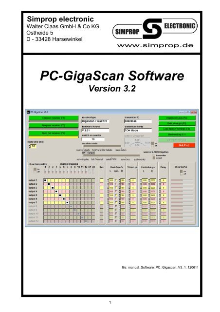
<strong>PC</strong>-<strong>GigaScan</strong> <strong>Software</strong><br />
Version 3.2<br />
file: manual_<strong>Software</strong>_<strong>PC</strong>_Gigascan_V3_1_120611
Table of content<br />
1. Introduction and safety instructions........................................................................................................3<br />
2. Installation ..................................................................................................................................................3<br />
3. Connecting the <strong>GigaScan</strong> receiver to the <strong>PC</strong> and starting the software .............................................4<br />
4. “Program receiver (F1)“ ............................................................................................................................6<br />
4.1. Connect receiver (F1) ..................................................................................................................................6<br />
4.2. Read out receiver (F2) .................................................................................................................................6<br />
4.2.1. receiver type..........................................................................................................................................6<br />
4.2.2. transmitter ID.........................................................................................................................................6<br />
4.2.3. firmware version....................................................................................................................................6<br />
4.2.4. transmitter mode ...................................................................................................................................6<br />
4.2.5. Switch-on counter .................................................................................................................................7<br />
4.2.6. battery voltage.......................................................................................................................................7<br />
4.3. Program receiver (F3) ..................................................................................................................................7<br />
4.4. Selectable parameters .................................................................................................................................7<br />
4.4.1. cycle time (impulse rate of channels) ...................................................................................................7<br />
4.4.2. receiver mode .......................................................................................................................................7<br />
4.4.3. DAT output ............................................................................................................................................8<br />
4.4.4. source S-PWM/GigaBus .......................................................................................................................8<br />
4.4.5. reverse- channel (Vario) .......................................................................................................................8<br />
4.4.6. channel mapping (transmitter - receiver)..............................................................................................8<br />
4.4.7. show transmitter....................................................................................................................................8<br />
4.4.8. Rev. (Reverse)......................................................................................................................................8<br />
4.4.9. Dual-Rate %..........................................................................................................................................9<br />
4.4.10. Trimm µs............................................................................................................................................9<br />
4.4.11. limitation µs........................................................................................................................................9<br />
4.4.12. Delay .................................................................................................................................................9<br />
4.4.13. show servo ........................................................................................................................................9<br />
4.5. Impulse display (F4).....................................................................................................................................9<br />
4.6. Field strength (F5)........................................................................................................................................9<br />
4.7. Load factory settings (F6) ..........................................................................................................................10<br />
4.8. Start binding (F7)........................................................................................................................................10<br />
4.9. Vario settings (F8)......................................................................................................................................10<br />
4.9.1. settings base station ...........................................................................................................................10<br />
4.9.2. settings <strong>GigaScan</strong> Vario .....................................................................................................................12<br />
4.9.3 Load factory settings (F6) ...................................................................................................................13<br />
4.10. Programming a GigaBus Decoder 5 ......................................................................................................13<br />
4.11. error messages.......................................................................................................................................14<br />
4.11.1. Transmission error ..........................................................................................................................14<br />
4.11.2. Not supported firmware!..................................................................................................................15<br />
4.11.3. Programming error ..........................................................................................................................15<br />
5. “Display telemetry data (F3)“..................................................................................................................16<br />
6. Licence agreement on <strong>PC</strong>-<strong>GigaScan</strong> software .....................................................................................20<br />
2
1. Introduction and safety instructions<br />
We have tested this software with different <strong>PC</strong>s and operating systems. Nevertheless we can not guarantee the<br />
function for every system. This is a free software: Please understand that we can not provide any support for<br />
problems with installation, your <strong>PC</strong>, the different functions, etc.<br />
System requirements:<br />
<strong>PC</strong> with Windows 2000 / XP / Vista / 7, 128MB working memory and USB-Port, about 50MB space on HDD.<br />
Read this instruction manual carefully before using this software. Thereby you get to know the different functions<br />
and avoid damage to your <strong>PC</strong>. Please pay attention to the following advice:<br />
This software, together with the <strong>Simprop</strong> <strong>PC</strong>-Interface USB, is designed for the use with radio controlled<br />
models. It is only allowed to use it for this purpose.<br />
Read this instruction manual and the license agreement carefully before installation. By instaling the<br />
software you accept the licence agreement.<br />
All trademarks and registered trademarks are the property of their respective owners.<br />
2. Installation<br />
1. Start your Windows Explorer.<br />
2. The files are packed to reduce their size and have to be UnZIPed first.<br />
3. Start the installation by double-clicking on the file „Setup“.<br />
4. Decide in which directory you want to install the software or click Finish to confirm the suggested one.<br />
5. If you want to install the program in a different directory, click Change. In the next window you can<br />
choose the drive and directory. Then click OK.<br />
Click OK to finish installation and to close the installation program.<br />
6. The software is now ready to use. Use the Start button of your windows to start the software.<br />
3
3. Connecting the <strong>GigaScan</strong> receiver 1 to the <strong>PC</strong> and starting the software<br />
To connect the <strong>GigaScan</strong> receiver to your <strong>PC</strong>, the following items are required:<br />
- <strong>Simprop</strong> <strong>GigaScan</strong> receiver or GigaBus Decoder<br />
- <strong>PC</strong>-Interface USB, order.-no. 012 412 5<br />
- receiver battery, possibly with switch<br />
Start the program via START-menu / Programme / <strong>PC</strong> <strong>GigaScan</strong>. The following window opens:<br />
(If the language is not set to english, please klick the flag)<br />
Proceed as follows:<br />
1. Install the drivers for the <strong>PC</strong>-Interface USB, if not done already.<br />
2. Connect the <strong>PC</strong>-Interface USB to the USB port of your <strong>PC</strong>. This will automatically generate a virtual<br />
Com-port.<br />
1 The same procedure is applied when connecting a GigaBus Decoder 5 (also see chapter 4.10)<br />
4
3. Select the Com-port where the <strong>PC</strong>-Interface USB is connected to. It is named “Silicon Labs CP210x<br />
USB to UART Bridge“.<br />
4. Connect the <strong>PC</strong>-Interface USB to the DAT-output of the receiver (<strong>GigaScan</strong> 5/5LX = output 5,<br />
<strong>GigaScan</strong> 7/9/9 Vario = output 7). Use only the two-core connection cable (brown, orange) which is<br />
included in the <strong>PC</strong>-Interface USB (Warning: Using other cables may destroy the USB port of your<br />
<strong>PC</strong>). Make sure that the brown wire of the connection cable is connected to the minus contact (-) of<br />
receiver and <strong>PC</strong>-InterfaceUSB. At the receiver the brown wire must be on the top side (where the<br />
<strong>GigaScan</strong> lettering can be read).<br />
5. Click the button “Connect receiver (F1)” and within 5 seconds switch on the <strong>GigaScan</strong> receiver (by<br />
connecting to battery/power supply). If you have missed to switch on within 5 seconds, click the button<br />
again and then switch on the receiver again.<br />
The <strong>PC</strong>-<strong>GigaScan</strong> <strong>Software</strong> makes a connection to the receiver and reads out receiver type and firmware<br />
version of the receiver. After successful connection the window looks like this:<br />
For programming the receiver click on “Program receiver (F2)“. The further desription can be found in<br />
chapter 4.<br />
For displaying telemetry data click on “Display telemetry data (F3)”. The further desription can be found in<br />
chapter 5.<br />
5
4. “Program receiver (F1)“<br />
After clicking “Program receiver (F1)” the following window appears:<br />
First the receiver is automatically read out, so that the current settings are visible.<br />
The <strong>PC</strong>-<strong>GigaScan</strong> <strong>Software</strong> has a clear structure and is almost self-explanatory. Nevertheless the following<br />
explanations and background information can be very helpful.<br />
4.1. Connect receiver (F1)<br />
If the connection to the receiver was interrupted, it can be connected again. Click the button “Connect receiver<br />
(F1)” and within 5 seconds switch on the <strong>GigaScan</strong> receiver (by connecting to battery/power supply). If you<br />
have missed to switch on within 5 seconds, click the button again and then switch on the receiver again.<br />
We recommend to use a switch between battery and receiver. If connecting was successful the receiver is read<br />
out and the current settings are displayed.<br />
4.2. Read out receiver (F2)<br />
Clicking this button reads out and displays the current settings of the receiver. The receiver must be connected<br />
to the <strong>PC</strong> (see 4.1).<br />
4.2.1. receiver type<br />
Shows the type of the connected receiver. For example „<strong>GigaScan</strong> 5“ or „<strong>GigaScan</strong> 7“<br />
4.2.2. transmitter ID<br />
Shows the ID (code) of the transmitter that is binded to the receiver. Every transmitter has a unique ID.<br />
4.2.3. firmware version<br />
Shows the version of the receiver´s firmware<br />
4.2.4. transmitter mode<br />
Shows the mode of the binded transmitter (3 channel mode, 7 channel mode or Multimode). The <strong>GigaScan</strong><br />
receivers automatically detect the mode of the transmitter at the binding procedure.<br />
6
4.2.5. Switch-on counter<br />
Shows how often the receiver has been switched on since the last binding. This function can be very<br />
helpful to detect malfunctions of the power supply. When the counter is heightened during flight, there<br />
seems to be a problem with the battery or the wiring. Maybe the battery is overloaded and voltgage dips<br />
are to low for the receiver (receiver resets) or there are loose contacts. Do not fly again before the problem<br />
is solved. The counter is reset to zero by doing a binding.<br />
4.2.6. battery voltage<br />
If the switch is moved to “on“, the battery voltage is displayed.<br />
4.3. Program receiver (F3)<br />
When this button is clicked the selected parameters and functions are programmed into the receiver.<br />
4.4. Selectable parameters<br />
The software offers a variety of parameters that can be set:<br />
4.4.1. cycle time (impulse rate of channels)<br />
The receiver tells the servos, speed controllers, etc. which position they have to go to. This communication<br />
takes place in cycles. The duration between the beginning of two signals is called cycle time.<br />
Generally speaking, short cycle times mean that the information from the transmitter is given faster and<br />
more often to servos, speed controller, etc. On the other hand short cycle times can make the control of the<br />
servo, etc. instable. When the servo gets to many information (cycle time to short), it can not proceed<br />
properly and starts scattering. This causes lower precision and a high current consumption. Scattering and<br />
instable control must be avoided.<br />
The factory setting of the <strong>GigaScan</strong> receivers is 20ms. This value is suitable for analog and digital servos.<br />
Especially digital servos can work with shorter cycle times (e.g. 14ms like many Futaba receivers have).<br />
Cycle times below 7ms make no sense at the moment, because the transmitter only sends new information<br />
every 7ms (Multimode) or 8ms (7 channel mode).<br />
Before setting the cycle time, please check which cycle time your components (servos, speed controllers,<br />
etc.) require. If you are uncertain about this, please leave the setting at 20ms.<br />
4.4.2. receiver mode<br />
The <strong>GigaScan</strong> receivers can be binded in different receiver modes. These are:<br />
receiver failsafe - Hold/transmitter failsafe<br />
Failsafe is a function that can help to minimize possible damage in case of disturbances of the<br />
transmission between transmitter and receiver or the breakdown of the transmitter. The failsafe function<br />
of the receiver realizes a disturbed transmission and brings all servos, speed controllers, etc. in a<br />
position that was set before or holds the last position before the transmission was disturbed (Hold). A<br />
sample reveals this: When the transmission is interrupted it makes sense to stop the motor to avoid<br />
further acceleration.<br />
In the <strong>PC</strong>-<strong>GigaScan</strong> <strong>Software</strong> you have the choice between “receiver failsafe” and “Hold/transmitter failsafe”.<br />
When you choose “receiver failsafe” the failsafe positions are the positions of the transmitter during<br />
binding. Attention: In this case make sure all sticks and switches of the transmitter are in the wanted<br />
failsafe positions during binding. When the transmission is interrupted for more than 1 second all servos<br />
go to these failsafe positions. If you want to change the failsafe positions, repeat the binding (press the<br />
binding button for 3 seconds, release when red LED blinks quickly). The settings of transmitter failsafe<br />
are not used in this case.<br />
When “Hold/transmitter failsafe” is set, all servos hold the last valid position in case of a disturbance<br />
for more than 1 second. Furthermore the failsafe settings of the transmitter are considered. Different<br />
settings can be made depending on your transmitter. Please see the manual of your transmitter.<br />
base station<br />
When using a <strong>GigaScan</strong> 9 Vario any <strong>GigaScan</strong> receiver with firmware 2.0 or higher can be binded as<br />
base station. The base station receives the telemetry data that is transmitted by the <strong>GigaScan</strong> 9 Vario<br />
and provides the data at different channel outputs:<br />
- channel output 1: Here the <strong>Simprop</strong> Info-Terminal can be connected. It displays the telemetry data<br />
on it´s LCD.<br />
- channel output 3: Here an earphone can be connected to signalize climbing and declining of the<br />
model acoustically and to give acoustic warning signals.<br />
7
- DAT output: Via the DAT output the receiver can be connected to a <strong>PC</strong> (requires optional <strong>PC</strong>-<br />
Interface USB). Using the <strong>PC</strong>-<strong>GigaScan</strong> <strong>Software</strong> telemetry data can be displayed and recorded<br />
(data logger). Also see chapter 5.<br />
4.4.3. DAT output<br />
Using this slider the function of the DAT output can be set. The following options are available:<br />
- servo impulse: normal channel output for servos, speed controllers, etc. (factory setting)<br />
- Info Terminal: data output to connect to the <strong>Simprop</strong> Info-Terminal<br />
- seriell PWM: output of a pulse chain that can control special units such as rigid systems or<br />
electronics of micro helicopters that work with this signal<br />
- servo bus: for receivers with firmware 2.0 or higher the DAT output can be configured as GigaBus<br />
output. The GigaBus signal contains all servopositions digitally coded. The GigaBus signal is<br />
compatible to the Futaba S.BUS. Components that work with this system such as <strong>Simprop</strong><br />
GigaBus Decoder 5, Futaba S.BUS servos, stabilizers, battery switches, etc. can be connected.<br />
- QuattroVersity (only for <strong>GigaScan</strong> 7 Quattro and <strong>GigaScan</strong> Satellite): For the <strong>GigaScan</strong> 7 Quattro<br />
and the <strong>GigaScan</strong> Satellite the DAT output can also be set as QuattroVersity in/output. This option<br />
enables you to connect a <strong>GigaScan</strong> Satellite and a <strong>GigaScan</strong> 7 Quattro or two <strong>GigaScan</strong> 7 Quattro<br />
with a patchcable (connect DAT outputs) and establish QuattroVersity operation. QuattroVersity<br />
means that both receivers work together and exchange the information they receive. There are<br />
four active antennas at a time. In case of receipt problems of one receiver the information is taken<br />
from the other receiver and vice versa. This avoids trouble in case of dead spots or bad antenna<br />
positioning.<br />
4.4.4. source S-PWM/GigaBus<br />
With this switch the signal source for the seriall PWM resp. the GigaBus can be set.<br />
transmitter<br />
When the switch is moved to “transmitter“ the servo positions from the transmitter are directed to the<br />
seriell PWM resp. servo bus output without any changes.<br />
output<br />
When the switch is moved to “output“ the serial PWM resp. the servo bus signal also includes the<br />
settings in the <strong>PC</strong>-<strong>GigaScan</strong> <strong>Software</strong> (channel mapping, Dual-Rate , Delay, etc.).<br />
4.4.5. reverse- channel (Vario)<br />
This switch can only be used when the connected receiver is a <strong>GigaScan</strong> 9 Vario.<br />
Using the switch the reverse-channel can be activated or deactivated. We recommend to deactivate the<br />
reverse-channel when the telemetry data is not needed in order to safe energy, reduce the internal heating<br />
of the receiver and reduce the traffic in the 2.4GHz band.<br />
4.4.6. channel mapping (transmitter - receiver)<br />
An important function of the <strong>GigaScan</strong> receivers is the free channel mapping where every tranmitter<br />
channel can be assigned to every receiver channel. This is set using the matrix in the lower left quarter of<br />
the window. The lines show the receiver channels, the columns show the transmitter channels.<br />
It is also possible to assign more than one receiver channel to a transmitter channel. Just click the fields to<br />
bring transmitter and receiver channels together. This feature makes many interesting functions possible:<br />
sample 1: A model has two servos for elevator. Some transmitter do not support this. Using the <strong>PC</strong>-<br />
<strong>GigaScan</strong> <strong>Software</strong> both servos can be assigned to the transmitter channel and in addition one of the<br />
servos can be reversed (Rev.).<br />
sample 2: „Multi-receiver-operation“. When a 12-channel receiver is needed you can combine a<br />
<strong>GigaScan</strong> 5 and a <strong>GigaScan</strong> 7. First bind both receivers to the transmitter. Then <strong>GigaScan</strong> 7 is assigned to<br />
channels 1-7 and <strong>GigaScan</strong> 5 to channels 8-12. You can also combine two or more <strong>GigaScan</strong> 5 or two or<br />
more <strong>GigaScan</strong> 7. One receiver per wing in your model airplane, an extra receiver for the tail of your model<br />
helicopter, one receiver in the truck, one in the trailer, …<br />
4.4.7. show transmitter<br />
In the upper left corner of the table is the switch “show transmitter”. When it is switched on and the<br />
transmitter that is binded to the receiver is switched on as well, the different channels are displayed. This is<br />
a very helpful feature while programming the channel mapping.<br />
4.4.8. Rev. (Reverse)<br />
Here the rotating direction of the receiver channels can be reversed.<br />
8
4.4.9. Dual-Rate %<br />
With the Dual-Rate function the servo movement can be set separately for left and right. The adjustable<br />
range is from 0 to 150%. When 100% (factory setting) is set, the servo movements are exactly as the stick<br />
of the transmitter is moved. When you click the field “sym.” (for symmetrical), the values for left and right<br />
are linked.<br />
4.4.10. Trimm µs<br />
With the „Trimm“ function the center of the servo can be moved. The adjustable range is from -200µs to<br />
+200µs, which is about 20% of the complete servo way. The factory setting is “0”.<br />
4.4.11. limitation µs<br />
With this function the servo ways can be limited separately for both directions. This can help to avoid that a<br />
rudder e.g. crashes into a mechanical limitation. When using the two digital switched channels of the<br />
Multimode, the selected positions are assigned to the switch setting.<br />
4.4.12. Delay<br />
With the delay function the movement of the servo can be slowed down. 0% means no delay, 99% is the<br />
maximum delay. When 99% is set, a complete movement from left to right takes about 10 seconds.<br />
This function is very useful to move retracts or airbrakes at scale speed.<br />
4.4.13. show servo<br />
This function is the counterpart to the display of the transmitter channels (show transmitter). It shows the<br />
positions of all receiver channels. It is a helpful function to check the settings before programming them<br />
into the receiver. Using the switch it can be enabled or disabled.<br />
4.5. Impulse display (F4)<br />
When this button is pressed, a new window opens where the different channels of the receiver are shown in bar<br />
graphs. Additionally the numeric value in milli-seconds (ms) is given. This function only works when the<br />
transmitter (that is binded to the receiver) is switched on.<br />
4.6. Field strength (F5)<br />
With this function the field strength of the 36 transmission channels (22 in France) is displayed. Furthermore it<br />
shows which of the two antennas is active. When the bars are green, receipt is OK. When the bars are red, the<br />
receipt is disturbed. This function is very useful to find the best place for the installation of the receiver and<br />
antennas by comparing.<br />
When several 2.4GHz systems are in use at the same time, short-time disturbances of channels (red bars) are<br />
possible and normal. In general the pilot will not realize them, because of the permanent hopping between the<br />
channels.<br />
9
Display of the field strength with 36 channels<br />
4.7. Load factory settings (F6)<br />
When this button is pressed the factory settings are loaded in the software. To program them into the receiver,<br />
click “Program receiver (F3)”. This brings the receiver back to the factory settings.<br />
4.8. Start binding (F7)<br />
With this button the binding is started without pressing the binding button on the receiver.<br />
4.9. Vario settings (F8)<br />
This button is only active when a <strong>GigaScan</strong> 9 Vario with activated reverse-channel or a <strong>GigaScan</strong> receiver with<br />
receiver mode “base station” is connected. Click the button.<br />
4.9.1. settings base station<br />
When a receiver with receiver mode “base station” is connected the new window looks like this:<br />
10
All parameters can be set in the left half of the window:<br />
position display<br />
All 28 parameters can be displayed in the <strong>Simprop</strong> Info-Terminal. Because the display does only have two<br />
lines only 2 parameters can be displayed at once. Using a free channel of the transmitter it is possible to<br />
step through the parameters (see chapter 4.9.2).<br />
The selection and order of the desired parameters can be set in this column. Parameters that are not<br />
needed can be deactivated by selecting “---”.<br />
text display<br />
In the fields of this column the names of the telemetry data can be entered. This is especially useful for the<br />
data that is provided via the MSB.<br />
alarm signal<br />
When an earphone is connected to the base station, alarm signals can be given to the pilot acoustically.<br />
There are four different tones that can be selected. The limits for the alarm signals are set in the <strong>GigaScan</strong><br />
9 Vario (see chapter 4.9.2)<br />
The alarm limits for the parameters that come from the MSB (position display 13-28) are set in the sensors.<br />
Please refer to the manuals of the sensors.<br />
11
4.9.2. settings <strong>GigaScan</strong> Vario<br />
When a <strong>GigaScan</strong> 9 Vario receiver with activated reverse-channel is connected the new window looks like<br />
this:<br />
All parameters can be set in the right half of the window:<br />
12
MPX sensor bus:<br />
With this switch the Multiplex-Sensor-Bus (MSB) of the <strong>GigaScan</strong> 9 Vario can be activated or deactivated<br />
(channel output 9). When it is “off” the channel output 9 is a normal servo output. When it is “on” MSB<br />
sensors can be connected.<br />
transmitter channel display switching<br />
When a <strong>Simprop</strong> Info-Terminal is connected to the base station it is possible to step through the different<br />
telemetry data using a free transmitter channel. This channel can be set here. It is recommended to use a<br />
switch, so that a comfortable operation is possible.<br />
transmitter channel vario sensivity<br />
Here a free transmitter channel to change the sensivity of the variometer in flight is set. Setting the vario<br />
sensivity means beginning from what climb/decline rate a tone can be heart at an earphone connected to<br />
the base station. When there is only little climbing and declining, the sensivity should be increased. For<br />
high climbing and declining (windy, thermal soaring) the sensivity should be lower. Depending on the pilots<br />
preferences the perfect value of sensivity must be found out.<br />
When transmitter channel is set “0“, the sensivity is fixed to the value that is selected in the field below.<br />
alarm tone if ...<br />
Here the limits for the 12 telemetry parameters that are available directly from the <strong>GigaScan</strong> 9 Vario can be<br />
set. The switch has three stages:<br />
“Off”: no alarm signal for this parameter<br />
“”: alarm when current value is higher than set limit<br />
The limits are set in the fields behind the parameters.<br />
The limits for parameters that are measured by external sensors on the MSB are set in the sensors<br />
directly. Please refer to the sensor manuals.<br />
4.9.3 Load factory settings (F6)<br />
Clicking this button sets all values to their factory settings.<br />
4.10. Programming a GigaBus Decoder 5<br />
The <strong>Simprop</strong> GigaBus Decoder 5 can also be programmed with the <strong>PC</strong>-<strong>GigaScan</strong> <strong>Software</strong>. The procedure is<br />
almost the same as with <strong>GigaScan</strong> receivers. Proceed as described in chapter 3. After successful connection<br />
click “Program receiver (F2)”. The following window opens:<br />
13
The following parameters can be set:<br />
cycle time<br />
channel mapping<br />
Rev. (Reverse)<br />
Dual-Rate<br />
Trimm<br />
Limitations<br />
Delay<br />
For a detailed description of these parameters see chapter 4.4.x. The functions “show transmitter“, “show servo”<br />
and battery voltage can also be activated (also see chapter 4.4.x for details).<br />
4.11. error messages<br />
4.11.1. Transmission error<br />
When this error message occurs the receiver must be connected to the software again. Connection can be<br />
interrupted when your <strong>PC</strong> is to slow or overloaded. Please check if there are applications that are not<br />
needed and close them. The functions “show transmitter”, “show servo” and “field strength” require a lots of<br />
data transmission. This may overload older and slower <strong>PC</strong>s. Leave these functions deactivated when<br />
connection is interrupted after activating these functions.<br />
14
4.11.2. Not supported firmware!<br />
This message may occur when connecting receiver and <strong>PC</strong>. Proceed as described in the error message<br />
and install the <strong>PC</strong>-<strong>GigaScan</strong> <strong>Software</strong> version 2.1.<br />
4.11.3. Programming error<br />
This error may occur after clicking “Program receiver (F3)“. Check the connection of <strong>PC</strong>, <strong>PC</strong>-Interface USB<br />
and receiver. Reconnect the receiver and retry programming.<br />
15
5. “Display telemetry data (F3)“<br />
Displaying telemetry data requires a telemetry data transmitting receiver (on the model side), in other words a<br />
receiver with reverse channel (e.g. <strong>GigaScan</strong> 9 Vario). Furthermore a telemetry data receiving receiver (on the<br />
pilots side), working as base station is required. This base station must also be tought from which data transmitting<br />
receiver it should receive. This is done by binding the base station to the reverse channel. The telemetry data<br />
receiving receiver must also be set to the receiver mode “base station”. For further info please refer to the manual<br />
of <strong>GigaScan</strong> 9 Vario.<br />
When the above requirements are met, the following window appears:<br />
On the left side all values of the telemetry parameters are displayed. The first 12 values are those, that are<br />
provided by the <strong>GigaScan</strong> 9 Vario itself. Values 13 to 28 are provided by additional sensors that are connected to<br />
the MSB connector of the <strong>GigaScan</strong> 9 Vario. If applicable an alarm is displayed (here temperature alarm).<br />
The alarm limits for parameters 1-12 are set in the <strong>GigaScan</strong> 9 Vario (see chapter 4.9.2). The alarm limits for<br />
parameters 13-28 are set in the sensors (see sensor manual).<br />
Parameters 1-12 have the following meaning:<br />
- battery voltage<br />
current voltage at the receiver<br />
- min.batt.voltage<br />
Minimum battery voltage that occured during operation (since last switching on). This value may help to<br />
detect a weak power supply of the receiver.<br />
- reception quality<br />
The reception quality shows how strong the incoming signal of the receiver is. This may help to improve the<br />
positioning of receiver and antennas.<br />
- temperature<br />
This temperature is the internal temperature of the receiver. Internal heating makes it always a little higher<br />
than the ambient temperature. The temperature should not be higher than 45°C.<br />
16
- air pressure<br />
This value is the absolute air pressure measured by the integrated barometer of the <strong>GigaScan</strong> 9 Vario. From<br />
this value height and vario are derived.<br />
- Vario sensivity<br />
This value shows the set vario sensivity. With a free channel of the transmitter it can be changed in flight.<br />
See chapter 4.9.2 on how to set the vario sensivity.<br />
- vario<br />
The value “vario“ shows the climb and decline of the model in meters per second. In the base station this<br />
value is transformed into a accoustic signal and can be heard on a connected earphone. The experienced<br />
pilot will realize areas of thermal lift and optimize the efficiency of the model and it´s drive.<br />
- height<br />
This value shows the height of the model above the starting position. The height of “0” is set when the<br />
<strong>GigaScan</strong> 9 Vario is switched on.<br />
- max.height<br />
This value shows the maximum height during flight. This value is set to “0“ when the <strong>GigaScan</strong> 9 Vario is<br />
switched on.<br />
- receive error<br />
This value shows how often receive errors occured during flight. Depending on flight duration, height and<br />
antenna installation this value may rise to several hundred errors. Generally speaking this is not a problem,<br />
because up to 140 protocols are transmitted every second. Improving the installation of the antennas will<br />
bring the number of errors to a minimum.<br />
- failsafe counter<br />
The failsafe counter shows how often a case of failsafe (no valid receipt for more than 1 second) occured<br />
during flight. The value should always be “0”. In case of a higher value, please check the installation of the<br />
receiver and the antennas and install them according to the instruction manual of your receiver.<br />
- switch-on counter<br />
This counter is always incremented when the receiver is switched on. During flight this value may not be<br />
incremented. If it is incremented during flight it means that the power supply of the receiver has broken down<br />
and that the receiver was reset. Check the power supply of your receiver and all cables and connectors.<br />
If necessary install a more powerful power supply and replace wires and connectors by thicker ones.<br />
This value is set to “0” when binding the receiver to a transmitter.<br />
To enable more comfortable reading, the values of height, vario, battery voltage, barometer and temperature are<br />
displayed in an instrument board also.<br />
Furthermore there is a graph curve where two parameters can be displayed. Which parameters are displayed can<br />
be selected. Selection can also be changed during operation. The values of all 28 parameters are recorded and<br />
can be saved, but only two values can be displayed at once.<br />
17
Above the graph curve there are five green buttons. They have the following functions:<br />
- Start(F1)<br />
Starts recording all 28 parameters and displaying 2 of them.<br />
- Stop(F2)<br />
Stops recording the 28 parameters and displaying 2 of them in the graph curve.<br />
- Reset(F3)<br />
Graph curve and recorded data are deleted.<br />
- Save(F4)<br />
Save recorded data as a text-file.<br />
- Load(F5)<br />
Load data from an existing text-file and display the data as a graph curve.<br />
With these functions it is possible to save and evaluate the data of one or more flights. The values are written into a<br />
text-file (separated by semicolon) and can be opened and evaluated with spreadsheet programs such as Microsoft<br />
Excel or others.<br />
18
In this example the flight of an electric glider was recorded. The graph curve shows height and temperature. The<br />
maximum height was 380m.<br />
19
6. Licence agreement on <strong>PC</strong>-<strong>GigaScan</strong> <strong>Software</strong><br />
Advice for the user: Read the following contract carefully. With the installation of the software you accept<br />
the terms and conditions of this contract. When you can not accept the tems and conditions of this<br />
contract, do NOT install this software and delete all related files from your system.<br />
1. Granting of a licence. <strong>Simprop</strong> electronic gives you the non-exclusive and not negotiable right to install this<br />
software on a <strong>PC</strong>. This license requires your agreement with all terms and conditions of the license agreement.<br />
You oblige yourself to use this software only according to this license.<br />
2. Cancellation. This license agreement is valid until it is cancelled. You can cancel it at any time by deleting the<br />
software and all it´s copies from your system.Furthermore <strong>Simprop</strong> electronic can cancel the agreement when<br />
any of the terms or conditions are violated. A cancellation obliges you to delete the software and all its copies.<br />
3. Copyright. This software is protected by law of the Federal Republic of Germany and by international law. You<br />
accept that you do not get the intellectual property of this software. Further you accept that <strong>Simprop</strong> electronic<br />
holds all rights and unrestricted property of this software. These copyrights are also applied to all copies of this<br />
software.<br />
4. Changes to the software. You oblige yourself that you are not trying to decompile, modify, transfer or<br />
disassemble this software or parts of it.<br />
5. No further warranty. <strong>Simprop</strong> electronic does not guarantee that this software works without failure. <strong>Simprop</strong><br />
electronic rejects to give any warranty on this software.<br />
6. Separation. If one of the terms and conditions in this agreement is invalid, it has no influence on the validity of<br />
the other terms and conditions.<br />
7. No warranty for subsequent damages. <strong>Simprop</strong> electronic and it´s suppliers are not liable to pay<br />
compensation for any subsequent damages, especially indirect or accidental damages that result from the use<br />
of this software, even if <strong>Simprop</strong> electronic was informed that such a damage could occur. In any case the<br />
warranty is limited to the amount you payed for the license, no matter if these claims result from contract law,<br />
claims for damages or other claims.<br />
8. Applicable law. This license agreement is solely based on the law of the Federal Republic of Germany and<br />
the judgements of German courts.<br />
Complete agreement. This is a complete agreement between you and <strong>Simprop</strong> electronic. All older agreements<br />
(written or verbal) regarding the same matter are invalid.<br />
20