BOTTLE COOLER / WINE COOLER - Gastroversum
BOTTLE COOLER / WINE COOLER - Gastroversum
BOTTLE COOLER / WINE COOLER - Gastroversum

Create successful ePaper yourself
Turn your PDF publications into a flip-book with our unique Google optimized e-Paper software.
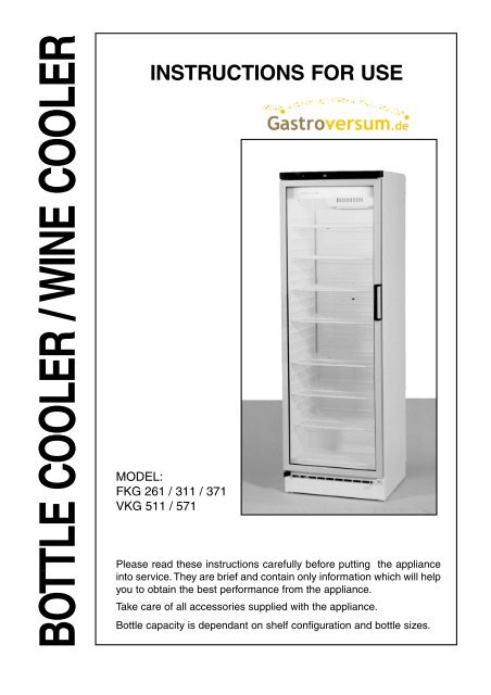
<strong>BOTTLE</strong> <strong>COOLER</strong> / <strong>WINE</strong> <strong>COOLER</strong><br />
INSTRUCTIONS FOR USE<br />
MODEL:<br />
FKG 261 / 311 / 371<br />
VKG 511 / 571<br />
Please read these instructions carefully before putting the appliance<br />
into service. They are brief and contain only information which will help<br />
you to obtain the best performance from the appliance.<br />
Take care of all accessories supplied with the appliance.<br />
Bottle capacity is dependant on shelf configuration and bottle sizes.
CONTENTS<br />
1. Before starting the appliance.<br />
2. How to use the appliance.<br />
3. Maintenance.<br />
4. Has the appliance stopped working?<br />
5. Safety.<br />
6. Technical data.<br />
7. Installation.<br />
8. Change of hinge side.<br />
9. Lighting fixture.<br />
1. BEFORE STARTING<br />
THE APPLIANCE<br />
Check that the cabinet is undamaged. Please<br />
report any damage immediately to your<br />
dealer. Wash the cabinet and inner lining with<br />
a mild unscented detergent and wipe it dry.<br />
Do not use abrasive scouring powder, steel<br />
wool or similar. Connection to the electricity<br />
supply: See head 7 and 8.<br />
2. HOW TO USE THE APPLIANCE<br />
Operating panel (see fig. (5) page 4.<br />
1. Thermostat knob.<br />
2. Indicator for the connection to the<br />
electricity supply (green).<br />
3. Switch for light.<br />
The thermostat knob is adjustable from 0<br />
(stop) to 7 (coldest). Find the position of the<br />
thermostat which gives you the desired<br />
temperature. Start at position 4.<br />
Defrosting<br />
The evaporator is automatically defrosted.<br />
The defrost water is led to a tray on top of the<br />
compressor where it evaporates.<br />
3. MAINTENANCE<br />
Only use an unscented detergent when cleaning<br />
the cabinet inside.<br />
You may remove the top panel and wash it<br />
when cleaning the cabinet inside.<br />
Switch off the appliance and pull out the plug<br />
when cleaning the cabinet.<br />
The skirting board can be removed to<br />
facilitate a vaccuum-cleaning of the floor. See<br />
fig. (1) page 5.<br />
2<br />
To make the cooling system work at its optimum<br />
it is necessary from time to time to clean<br />
the wire condenser and the compressor at<br />
the back of the cabinet by means of a brush<br />
or a vaccuum cleaner. Remember to clean<br />
the drain.<br />
IMPORTANT! I<br />
n case of damage to the power cord it must<br />
be replaced by a power cord of corresponding<br />
type, available from the manufacturer or his<br />
service representative.<br />
4. HAS THE APPLIANCE STOPPED<br />
WORKING?<br />
Before calling a repairman, check that<br />
l The plug is properly plugged into the wall<br />
socket.<br />
l The fuse is intact.<br />
l The power has not been cut off.<br />
l All controls are correctly set.<br />
l Switch off the cabinet for 15 minutes (for<br />
instance at the thermostat). Switch it on<br />
again and after 5 minutes check whether<br />
frost has formed on the evaporator.<br />
l Do not open the cabinet when<br />
unnecessary.<br />
5. SAFETY<br />
Do not store explosive substances in the<br />
refrigerator section, such as gas, cigarette<br />
lighters, petrol, ether or similar. Scrapped<br />
cabinets may become dangerous to children<br />
at play. Therefore, remove the doors or place<br />
the scrapped cabinet in such a way that<br />
children cannot enter it.<br />
Never store liquids with carbon dioxide in the<br />
freezing section.<br />
6. TECHNICAL DATA<br />
This appliance meets the provisions of the<br />
following directives: 89/336/EEC (electromagnetic<br />
compatibility), 73/23/EEC (electrical<br />
equipment designed for use within certain<br />
voltage limits) as amended.<br />
The rating plate, which is placed inside the<br />
appliance (see fig. (6) page 4), provides<br />
various technical information as well as type<br />
and serial number.
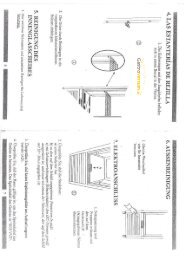
7. INSTALLATION<br />
See drawings - fig. 1 page (5) - fig. (1), (2)<br />
and (3) page 6.<br />
Install the cabinet in a dry place and so that<br />
it is not exposed to direct sunlight or any other<br />
source of heat.<br />
Place the cabinet in a level position. This is<br />
easily achieved by adjusting the adjustable<br />
feet at the front edge of the base. The cabinet<br />
may not rest against a wall on its hinged side.<br />
When placing the cabinet on a carpet or on<br />
a wooden floor you should adjust it once<br />
more after some time as the cabinet might<br />
settle in soft foundations.<br />
If you want to build the appliance into a cupboard<br />
you must consider 3 factors:<br />
1. There must be space above the<br />
appliance in order to make the cooling<br />
system work satisfactorily. - Fig. (1) page<br />
6.<br />
2. When the door is opened the appliance<br />
takes up more room in the width and<br />
therefore the door must either be placed<br />
outside the cupboard or there must be<br />
a space of at least 15 mm at the hinge<br />
side. - Fig. (2B) page 6.<br />
3. The distance to the wall at the hinge<br />
side must be of a sufficient size. - Fig.<br />
(2B) page 6.<br />
In addition, the bottle cooler may be built in<br />
or positioned alongside another unit – fig.<br />
(3) page 6.<br />
If the wine cooler is to be placed next to<br />
another unit, a 25 mm gap must be left.<br />
Any local installation rules for appliances of<br />
this kind must be observed.<br />
During a storm the electricity supply might<br />
be cut off.<br />
You should be aware of this when installing<br />
the appliance in weekend cottages or<br />
elsewhere where you would not immediately<br />
observe that the power has been cut off.<br />
Construction and details in the accessories<br />
are subject to alteration without previous<br />
notice.<br />
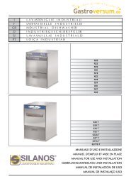
8. CHANGE OF HINGE SIDE<br />
Follow the instructions below if you wish to<br />
install the door hinges at the opposite side.<br />
See the drawings on page 7.<br />
Dismantle the top panel cover - (1) and (2).<br />
Dismantle the top hinge. To be used later as<br />
bottom hinge at the opposite side - (3).<br />
Dismantle the door and its bushing.<br />
Dismantle the bottom hinge - (6).<br />
Place the tension disk and the counter nut<br />
for the hinge pivot on the new bottom hinge.<br />
Mount the door anew.<br />
Tighten the counter nut at the bottom.<br />
Tighten up all nuts.<br />
Mount anew top panel cover and skirting<br />
board cover.<br />
9. LIGHTING FIXTURE<br />
See the drawing on page 7.<br />
1. Pull the screen to the left.<br />
2. Pull down the right side of the screen<br />
and take it out.<br />
- Remove the strip - possibly with text - by<br />
pulling it out of the tracks along the whole<br />
length of the profile.<br />
- The fluorescent tube can be replaced.<br />
The mounting is performed in reverse order.<br />
The glow switch can be replaced without<br />
removing the screen.<br />
DISPOSAL OF THE<br />
APPLIANCE<br />
The appliance contains recyclable<br />
materials. When disposing of the<br />
appliance, please contact the technical<br />
administration or other appropriate<br />
authority in your municipality. They can<br />
inform you of the collection and recycling<br />
measures used in the municipality.<br />
3
4<br />
Fig. 4<br />
Fig. 5<br />
Fig. 6<br />
Mounting of lock for one-door uprights.<br />
Aptional extras.
Ì<br />
Ì<br />
Fig. 1<br />
Ì Ì<br />
Ì<br />
5
6<br />
min. 1400/1700/2000<br />
Fig. 2A<br />
600<br />
Fig. 2B<br />
25<br />
min. 15<br />
min. 1040<br />
150<br />
1250/1550/1850<br />
Fig. 3<br />
min. 25 mm
CHANGE OF HINGE SIDE<br />
1 2<br />
7<br />
3<br />
6<br />
7