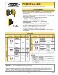
ULTRA-BEAM™ 923 Series - Banner Engineering
ULTRA-BEAM™ 923 Series - Banner Engineering
ULTRA-BEAM™ 923 Series - Banner Engineering

Create successful ePaper yourself
Turn your PDF publications into a flip-book with our unique Google optimized e-Paper software.
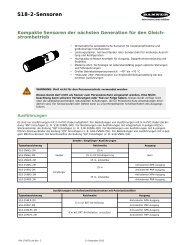
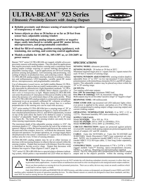
<strong>ULTRA</strong>-BEAM<br />
Ultrasonic Proximity Sensors with Analog Outputs<br />
<strong>923</strong> <strong>Series</strong><br />
Reliable proximity and distance sensing of materials regardless<br />
of transparency or color<br />
Senses objects as close as 20 inches or as far as 20 feet from<br />
sensor face; adjustable sensing window<br />
Sourcing and sinking analog outputs, positive or negative<br />
slope; easily interfaced to variable speed DC motor drives,<br />
microprocessors, and programmable controllers<br />
Ideal for fill level sensing, position sensing (guidance), web<br />
tensioning, size sorting, and centering control applications<br />
Models available for 18-30V dc, 105-130V ac, or 210-260V ac<br />
power source<br />
<strong>Banner</strong> "<strong>923</strong>" series <strong>ULTRA</strong>-BEAMs are rugged, reliable ultrasonic<br />
proximity sensors with analog outputs. They are ideal for applications<br />
that require proximity mode distance sensing and a continuous linear<br />
analog output (voltage sourcing or current sinking) throughout an<br />
adjustable sensing range. Typical applications are fill level sensing,<br />
position sensing and guidance, web tensioning and positioning, size<br />
sorting of objects on production lines, and centering control. <strong>Banner</strong><br />
<strong>ULTRA</strong>-BEAM analog outputs interface directly to ordinary voltmeters<br />
and milliammeters, LED bargraphs, variable speed DC motor<br />
drives, microprocessors, and programmable controllers.<br />
Use of ultrasonics (sound waves, not light) enables <strong>Banner</strong> <strong>ULTRA</strong>-<br />
BEAMs to detect objects that are totally undetectable or only marginally<br />
detectable by photoelectric (light dependent) methods. <strong>ULTRA</strong>-<br />
BEAM ultrasonic sensors can reliably detect objects regardless of<br />
their color or transparency to light. <strong>Banner</strong> analog <strong>ULTRA</strong>-BEAMs<br />
can sense the presence of clear glass or film just as reliably as they can<br />
detect the presence of a solid metal object of the same profile. When<br />
one of <strong>ULTRA</strong>-BEAM's analog outputs is connected to an appropriate<br />
instrument (even an accurately calibrated DC voltmeter or milliammeter<br />
will suffice) the distance from the sensor face to a surface<br />
perpendicular to the sensing axis can be read with accuracy.<br />
"<strong>923</strong>" series analog <strong>ULTRA</strong>-BEAMs have a sensing range of 20" to<br />
20', with the response pattern shown in figure A. Easily-accessible 15turn<br />
clutched potentiometers (NULL and SPAN adjustments, located<br />
on top of the unit) allow the limits to be shifted to create a "sensing<br />
window" of adjustable "depth" anywhere within the 20" to 20' range<br />
(see figure B). The limits of the sensing window can easily be reset<br />
when sensing requirements change.<br />
The maximum depth of the adjustable sensing window is 18'4"; the<br />
minimum depth is 12". Objects beyond the far end of the window are<br />
ignored. Objects within the beam pattern and between the sensor and<br />
the near end of the window, however, will block the ultrasonic beam<br />
and prevent operation. For proper operation, an average target object<br />
should present to the sensor a minimum of 1 square foot of reflective<br />
surface area for every 10 feet of sensing distance.<br />
<strong>ULTRA</strong>-BEAM's analog outputs may be set to either increase or<br />
decrease with increasing distance to objects that are sensed within the<br />
sensing window. Output that increases with distance from the sensor<br />
is described as having positive slope. Output that decreases with<br />
distance has negative slope (figures E and F, page 4).<br />
"<strong>923</strong>" series <strong>ULTRA</strong>-BEAMs have a special relative distance indicating<br />
system, which pulses a top-mounted red LED when an object is<br />
SPECIFICATIONS<br />
SENSING MODE: ultrasonic proximity<br />
SENSING RANGE: 20 inches to 20 feet at 20°C.<br />
Minimum required target area is 1 square foot (0,1 square meter) for<br />
each 10 feet (3 meters) of sensing range.<br />
SENSING WINDOW ADJUSTMENTS: sensing window depth is<br />
adjustable from 12" to 18'4" via two top-mounted 15-turn clutched<br />
potentiometers with slotted brass elements (NULL and SPAN adjustments).<br />
This adjustable window may be placed anywhere within the<br />
20" to 20' sensing range.<br />
OUTPUTS:<br />
Two analog solid-state outputs:<br />
0 to +10V dc (sourcing); minimum 500Ω load<br />
0 to 20mA dc (sinking); 4.0V dc maximum voltage drop<br />
Both outputs may be set for either "positive slope" or "negative slope"<br />
RESPONSE TIME: 100 milliseconds<br />
INDICATOR LED: top-mounted red LED indicator lights whenever<br />
power is applied to the sensor, and pulses at a 0 to 10Hz rate<br />
which is proportional to analog output voltage (sourcing output) and<br />
current (sinking output)<br />
OPERATING TEMPERATURE RANGE: 0 to 50°C (+32 to<br />
122°F). Maximum humidity 90% (non-condensing conditions).<br />
SUPPLY VOLTAGE:<br />
Model SU<strong>923</strong>QD: 18 to 30V dc, 5VA<br />
Model SUA<strong>923</strong>QD: 105 to 130V ac (50/60Hz), 5VA<br />
Model SUB<strong>923</strong>QD: 210 to 260V ac (50/60Hz), 5VA<br />
CIRCUIT PROTECTION: inputs are protected against polarity<br />
reversal (DC models); both analog outputs are protected against short<br />
circuit of outputs (AC and DC models).<br />
CABLE: 4-pin (for SU<strong>923</strong>QD) or 5-pin (for SUA<strong>923</strong>QD and<br />
SUB<strong>923</strong>QD) Quick Disconnect ("QD") type connectors are standard.<br />
NOTE: use 4-conductor (model MBCC-412) or 5-conductor<br />
(model MBCC-512) SO-type cable, 12 feet long (order separately,<br />
see page 6).<br />
CONSTRUCTION: overall dimensions 4.7"H x 2.0"W x 1.9"D;<br />
rugged molded Valox housing; epoxy-encapsulated circuitry.<br />
NEMA 1, 3, and 12. Mounting nut and lockwasher supplied.<br />
sensed. The 0 to 10Hz pulse rate is proportional to the sensor's analog<br />
output and to the object's position within the sensing window.<br />
WARNING These ultrasonic sensing devices do NOT include the self-checking redundant circuitry necessary to allow their use<br />
in personnel safety applications. A sensor failure or malfunction can result in either an energized or a de-energized sensor output condition.<br />
! Never use these products as sensing devices for personnel protection. Their use as safety devices may create an unsafe condition which<br />
could lead to serious injury or death.<br />
Only MACHINE-GUARD and PERIMETER-GUARD Systems, and other systems so designated, are designed to meet OSHA and ANSI<br />
machine safety standards for point-of-operation guarding devices. No other <strong>Banner</strong> sensors or controls are designed to meet these standards, and they<br />
must NOT be used as sensing devices for personnel protection.<br />
Printed in USA P/N 03488 rev. C
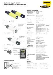
FIGURE A: Response Pattern, "<strong>923</strong>" <strong>Series</strong> Sensors<br />
1) The "sensing axis" is an imaginary<br />
line originating at and perpendicular<br />
to the center of the<br />
transducer.<br />
2) Response pattern is drawn for<br />
a 2 square foot smooth, solid surface.<br />
3) Symmetry of the pattern may<br />
be assumed in all sensing planes.<br />
4) The rounded portion of the<br />
curve past the 20' point indicates<br />
an area where sensing is unreliable.<br />
Effective range is from 20"<br />
to 20' (0,5 to 6m).<br />
6<br />
B<br />
E 4<br />
A<br />
M 2<br />
F<br />
W<br />
E 0<br />
I<br />
E<br />
D<br />
T 2<br />
T<br />
H 4<br />
6<br />
"<strong>923</strong>" series <strong>ULTRA</strong>-BEAMs<br />
SENSING AXIS<br />
0 5 10 15 20 25<br />
DISTANCE TO 2FT X 2FT TARGET--FEET<br />
BASIC THEORY OF <strong>ULTRA</strong>SOUND<br />
How Ultrasonics are Generated<br />
Ultrasonics are sound waves of frequencies above the range of human<br />
hearing. Like all sound waves, ultrasonic waves (or "ultrasound") are<br />
produced by a vibrating object. In <strong>ULTRA</strong>-BEAM sensors, the<br />
vibrating object is called a transducer. It is constructed of thin, highly<br />
flexible gold-plated plastic foil stretched over an aluminum backplate<br />
which is held in place by a leaf spring. The transducer is part of an<br />
electrical circuit, and vibrates when an AC voltage (of the desired<br />
operating frequency of the transducer) is applied to it. This vibration<br />
causes an audible "ticking" sound from the transducer. The sound is<br />
normal: each "tick" is a string of 16 ultrasonic sensing pulses.<br />
The AC voltage, which can be visualized as a sine wave, alternately<br />
compresses and expands the transducer. This action compresses and<br />
expands the air molecules in front of the sensor, sending "waves" of<br />
ultrasonic sound outward from the transducer's face. In <strong>ULTRA</strong>-<br />
BEAM sensors, the transducer is not constantly transmitting ultrasonic<br />
sound, but instead is switched "on" and "off" at a regular rate. During<br />
the "off" times (in between "ticks"), the transducer acts as a receiver and<br />
listens for ultrasonic waves reflected from objects in its path.<br />
Behavior of Ultrasonic Waves<br />
A basic knowledge of how ultrasonic waves behave in air can be of help<br />
in using ultrasonic sensors successfully:<br />
(1) The intensity of ultrasonic sound decreases with the square of<br />
the distance from the sound source. For example, if the intensity of<br />
ultrasonic sound at a distance of 1' in front of the sensor is designated<br />
as "1", then the intensity at 3 times that distance is (1/3) 2 , or 1/9th.<br />
If the radiated sound hits an object and is reflected back to the<br />
transducer, the object becomes the "source" for the waves on the return<br />
trip, and the intensity of the waves is reduced again by the square of the<br />
distance. The stronger the generated ultrasonic waves, the stronger<br />
will be the returned waves. And, the more efficient the object is as a<br />
reflector of ultrasonic waves, the stronger will be the returned waves.<br />
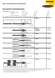
FIGURE B: "Sensing Window" Concept<br />
0<br />
SENSING WINDOW: depth adjustable from 12" to 18'4";<br />
sensing window may be placed anywhere between NEAR<br />
and FAR limits of sensor.<br />
20' = FAR SENSING LIMIT OF SENSOR and<br />
FAR LIMIT OF SENSING WINDOW<br />
20" = NEAR SENSING LIMIT OF SENSOR and<br />
NEAR LIMIT OF SENSING WINDOW<br />
5 10 15 20 25<br />
DISTANCE FROM SENSOR--FEET<br />
"QD" (Quick Disconnect) connectors are standard on <strong>ULTRA</strong>-BEAM<br />
sensors. DC models use a 4-pin connector; AC models use a 5-pin<br />
connector. Mating 12-foot SO-type cables must be ordered separately.<br />
Three sensor models are available, based on operating (power supply)<br />
voltage: model SU<strong>923</strong>QD for 18-30V dc, model SUA<strong>923</strong>QD for 105-<br />
130V ac, and model SUB<strong>923</strong>QD for 210-260V ac (see specifications).<br />
<strong>ULTRA</strong>-BEAM "<strong>923</strong>" series sensor housings are constructed of<br />
tough, corrosion-proof molded Valox . Electronic circuitry is epoxy<br />
encapsulated for shock and vibration resistance. The ultrasonic<br />
transducer (protected by a stamped metal screen) will not be damaged<br />
by temporary contact with moisture, but should be kept free of<br />
condensation and contamination for optimum operation.<br />
The <strong>Banner</strong> model SMB900 two-axis mounting bracket is ideal for use<br />
with "<strong>923</strong>" series sensors.<br />
(2) Ultrasonic waves are affected by the size, density, orientation,<br />
shape, surface , and location of the object being sensed.<br />
a) Size of the object: at a given distance in front of the sensor, a large<br />
object reflects more ultrasonic energy than does a smaller, otherwise<br />
identical object at the same position, and so is more easily sensed. The<br />
recommended object size for "<strong>923</strong>" series sensors is 1 square foot of<br />
reflective surface area presented to the sensor for each 10' of sensing<br />
distance. This is an "average figure", and is influenced by other characteristics<br />
of the object being sensed.<br />
b) Density of the object: density is the mass of an object per unit of<br />
volume. The more dense the object being sensed, the stronger is the<br />
sound reflection, and the more reliably the object can be sensed. This<br />
fact calls to mind experiences with audible sound in everyday life. For<br />
example, a wall covered with hardboard paneling reflects sound more<br />
efficiently than does a wall covered only by foam insulation panels. The<br />
hardboard paneling is denser than the foam. Ultrasonics are affected<br />
similarly. Note that water and other liquids (although they are certainly<br />
not solid) are nonetheless denser than materials like foam. This makes<br />
them better reflectors than foam. The table on the next page lists some<br />
materials and their relative effectiveness as ultrasonic reflectors.
TABLE: Relative Effectiveness of Various Materials as<br />
Reflectors of Ultrasound (rough order, best to worst)<br />
Smooth, flat steel plate (best)<br />
Smooth, flat plywood sheet<br />
Undisturbed liquid surface<br />
Aggregate (coal, ore, etc.)<br />
Smooth, flat corrugated cardboard<br />
Foam insulation panel<br />
Fine particulates (flour, grain, etc)<br />
Liquid with heavy surface foam<br />
Wool, cotton, felt<br />
Fiberglass insulation (worst)<br />
General rules:<br />
1) The higher the density of the object, the stronger the reflection.<br />
2) The smoother the surface of the object, the stronger the reflection.<br />
c) Object orientation, shape, and surface characteristics: Ultrasonic<br />
waves follow the same laws of reflection as do light waves. The<br />
angle of incidence equals the angle of reflection. This means that<br />
ultrasonic waves are reflected from a smooth, flat surface at the same<br />
angle (to the surface) as the angle at which they arrive. A perfectly flat<br />
object that is exactly perpendicular to the direction of travel (the "axis")<br />
of the ultrasonic waves will reflect the waves back along the same path<br />
(figure C). Objects thus oriented produce strong reflections when<br />
sensed.<br />
As the object's reflecting surface is tilted away from the axis of the<br />
waves, however, less and less of the ultrasonic signal is reflected back<br />
to the sensor. Eventually the point is reached beyond which the object<br />
can no longer be sensed. When attempting to sense an object with a flat,<br />
smooth, highly reflective surface, the angle of the reflecting surface to<br />
the sensing axis should never be more than 3°off of perpendicular.<br />
Irregularly shaped objects and aggregate matter (coal, ore, sand, flour,<br />
etc.) have many reflecting faces of many different angles. Although this<br />
scatters much of the ultrasonic energy away from the sensor, enough<br />
sound energy may be reflected back to the sensor for reliable sensing.<br />
In fact, due to the large number of reflecting surfaces, the "perpendicularity<br />
requirement" for smooth objects is not nearly as critical for these<br />
materials. Sensor angles of up to several degrees away from perpendicular<br />
often produce adequate reflections (figure D). Some materials<br />
may actually produce just as good reflections when sensed "at an angle"<br />
as when sensed "straight on". This allows a degree of freedom in<br />
choosing a sensor mounting location for some applications. Some trialand-error<br />
experimentation may be required.<br />
d) Location of the object within the sensor's response pattern: the<br />
ultrasonic signal radiated from the <strong>ULTRA</strong>-BEAM is strongest along<br />
the axis of the response pattern (the "sensing axis"), and drops off with<br />
increasing angle away from the axis. Objects can be most reliably<br />
sensed when they are as close as possible to the sensing axis.<br />
e) Location of sidewalls with respect to the beam pattern. Sidewalls<br />
located close to the sensing axis may sometimes cause unwanted signals<br />
to be reflected back to the sensor. Unwanted reflections may also occur<br />
from deposits of material adhering to the sidewalls of silos, tanks, etc.<br />
If possible, align the sensor so that its beam pattern will not encounter<br />
sidewalls, and try to keep sidewalls free of buildup.<br />
3) Extreme environmental conditions may affect ultrasonic sensing.<br />
Factors which may need to be considered include: temperature,<br />
high winds, high levels of sounds of certain types, humidity, atmospheric<br />
pressure, and dirt or moisture on the transducer.<br />
a) The speed of sound increases and decreases slightly with increases<br />
and decreases in ambient temperature. A large temperature<br />
increase will move the window slightly towards the sensor. A large<br />
temperature decrease will move the window slightly away from the<br />
sensor.<br />
The amount of shift is 3.5% for every 20°C of temperature change. For<br />
this reason, it is a good idea to set the sensing window limits when<br />
the ambient temperature is midway in the expected environmental<br />
operating temperature range of the sensor. Also, whenever it is<br />
consistent with the application, adjust the sensing window so that<br />
the object(s) to be sensed will pass as much as possible through the<br />
midpoint of the window.<br />
Fluctuations in the speed of sound can result when hot objects are<br />
sensed. A small fan directed along the sensing axis can help to thermally<br />
stabilize the sensing path and make accurate readings possible.<br />
b) In outdoor applications, crosswinds can blow an ultrasonic beam<br />
off target. The effect becomes more noticeable as the wind velocity and<br />
the distance to the object being sensed increase. Try to avoid sensing<br />
in areas of high crosswinds. When it is necessary to use ultrasonics in<br />
windy areas, keep the sensing range as short as possible, and shield the<br />
area from the wind as effectively as possible. Winds blowing steadily<br />
along the sensing axis, toward or away from the sensor, have less effect.<br />
Gusty winds along the sensing axis may affect output stability.<br />
c) Care should be taken to shield ultrasonic sensors from sustained,<br />
loud sounds such as factory whistles and similar sources. Sound<br />
sources produce harmonics (sounds at frequencies above the fundamental<br />
frequency of the source). Harmonics may fall in the ultrasonic<br />
range and "confuse" ultrasonic sensors. High pressure air blasts are<br />
especially good producers of harmonics in the ultrasonic range. Since<br />
sound waves travel in a straight line from the harmonic source to the<br />
sensor, the solution is simple: a wall or baffle placed between the<br />
sensor and the harmonic source is nearly always all that is required. This<br />
tactic can also help prevent interference between adjacent ultrasonic<br />
sensors.<br />
d) Humidity influences ultrasonic sensing by a maximum of 2% with<br />
extreme changes of humidity. The speed of sound increases with<br />
increasing humidity. Heavy atmospheric fog can increase sound<br />
absorption and reduce sensing range.<br />
e) Atmospheric pressure: a 5% increase in atmospheric pressure<br />
increases the speed of sound by 0.6%. A 5% decrease in pressure slows<br />
the speed of sound by 0.6%.<br />
f) Condensation or other contamination on the transducer face can<br />
seriously impede sensor performance, and should be avoided. In<br />
order to function, the transducer must be able to vibrate freely and at a<br />
high rate. Condensation or particulates on the transducer dampens its<br />
movement. While the transducer is not harmed by mists or noncondensing<br />
humidity, it should be clean and dry to operate most<br />
effectively.<br />
Most contamination can be prevented by mounting the sensor in the<br />
driest, cleanest location possible that still allows reliable sensing<br />
performance in a given application. Never mount the sensor "face<br />
up" in areas where contamination might be a problem.
<strong>ULTRA</strong>SONIC SENSING WITH BANNER "<strong>923</strong>" SERIES <strong>ULTRA</strong>-BEAMS<br />
In simplest terms, <strong>ULTRA</strong>-BEAM ultrasonic sensors operate by transmitting<br />
ultrasonic sound pulses of a specific frequency (inaudible to the<br />
ear) and, in between the transmitted pulses, listening for reflected pulses<br />
("echoes") of the same frequency from an object in the path of the<br />
ultrasonic beam. The sensor "knows" the speed of ultrasound and<br />
measures the time lapse between the transmitted ultrasonic pulses and<br />
the reflected echoes. The result is an analog output which represents the<br />
distance from the sensor to the reflecting object. If the distance between<br />
the sensor and the object changes, the <strong>ULTRA</strong>-BEAM sees a change in<br />
the time lapse and, within 100 milliseconds, updates and puts out new<br />
analog values. "<strong>923</strong>" series analog ultrasonic sensors can not only<br />
detect the presence of an object, but also give a continuous indication<br />
of the object's position along the sensing axis. (Note: the receiver must<br />
receive an "echo" in order to update its output. This echo usually is<br />
produced by the objects being sensed. If the object is removed from the<br />
sensing window, the next "update" echo may come from any object<br />
within the sensor's beam pattern, either inside or outside the sensing<br />
window.)<br />
By means of the internal SLOPE SELECT jumper switch, <strong>ULTRA</strong>-<br />
BEAM's analog outputs may be set to produce either a positive or<br />
negative slope. When adjusted for positive slope, the <strong>ULTRA</strong>-BEAM's<br />
analog outputs (both voltage sourcing and current sinking) increase as<br />
the object being sensed moves away from the sensor along the sensing<br />
axis (figure E).<br />
FIGURE E. POSITIVE SLOPE ANALOG OUTPUT<br />
Analog output increases as distance to target<br />
object increases. Near and far distances of<br />
sensing window are set by NULL and SPAN<br />
controls, respectively. The sloping line<br />
represents the sensing window. Analog<br />
output is linear within the window.<br />
ADJUSTMENT OF "<strong>923</strong>" SERIES SENSORS<br />
Installation and adjustment of "<strong>923</strong>" series <strong>ULTRA</strong>-BEAMs is performed<br />
as described below. Some means of monitoring the <strong>ULTRA</strong>-<br />
BEAM's analog output(s) is necessary. This can be done either by the<br />
"final device" in the application or by a voltmeter or milliammeter connected<br />
as shown in figures J, K, L, & M.<br />
1) Choose either voltage sourcing or current sinking output, and<br />
either positive slope or negative slope. The choice of sourcing or<br />
sinking output will depend upon the input requirements of the instrument<br />
that the <strong>ULTRA</strong>-BEAM will be connected to.<br />
The choice of positive or negative slope will depend upon the requirements<br />
of the "final device" used and the "direction" of the "action" that<br />
the analog output is to control or monitor. Positive slope analog output<br />
(figure E) increases with increasing distance to the target object;<br />
negative slope analog output (figure F) decreases with increasing<br />
distance to the target object. The maximum and minimum output levels,<br />
when set, will define the sensing window: the sourcing output range is<br />
0 to +10V dc; the sinking output range is 0 to 20mA dc. The sensor's<br />
analog output is linear within these ranges.<br />
Refer to the Dimension Drawing (p. 2) and figure G. Disconnect<br />
power from the sensor. Remove the front panel of the sensor by<br />
removing the four mounting screws at the four corners of the rear panel.<br />
Set the sensor for POSITIVE or NEGATIVE slope by positioning the<br />
jumper clip on the POS/NEG SLOPE SWITCH behind the front panel<br />
in the appropriate position. Replace the panel.<br />
2) Determine where the <strong>ULTRA</strong>-BEAM will be mounted and the<br />
proper position and "depth" of the sensing window.<br />
Best results will be obtained when the <strong>ULTRA</strong>-BEAM is adjusted<br />
When adjusted for negative slope, both analog outputs decrease as the<br />
object moves away from the sensor along the sensing axis (figure F).<br />
Figures E and F are typical responses for applications like fill level<br />
sensing, position sensing, and web tensioning, where movement along<br />
the sensing axis toward and away from the sensor must be monitored<br />
and/or controlled.<br />
Reliable distance sensing is possible for objects crossing the beam<br />
pattern at right angles to the sensing axis. In both the positive and the<br />
negative slope modes, an object moving along a path perpendicular to<br />
the sensing axis will begin to produce an analog output as it enters the<br />
sensor's pattern. Output will continue until the object moves out of the<br />
<strong>ULTRA</strong>-BEAM's sensing pattern.<br />
<strong>ULTRA</strong>-BEAM sensors may also be used to detect size differences in<br />
objects that are moving past the sensor at right angles to the sensing<br />
axis, as on a conveyor. It is best to think of the objects as being<br />
differentiated by their distance from the sensor rather than by their<br />
actual size. The surfaces of the objects being sensed must be presented<br />
to the sensor in such a way that size differences in the objects are seen<br />
as dimensional differences along the sensing axis. These distances can<br />
be detected by the sensor as changing sensor-to-object distances from<br />
one object to another, and can be differentiated by changes in the analog<br />
output.<br />
FIGURE F. NEGATIVE SLOPE ANALOG OUTPUT<br />
Analog output decreases as distance to target object<br />
increases. Near and far distances of sensing window<br />
are set by SPAN and NULL controls, respectively. The<br />
sloping line represents the sensing window. Analog<br />
output is linear within the window.<br />
Figure G: <strong>ULTRA</strong>-BEAM Slope Select Jumper Setting<br />
Gently pull the black jumper to remove;<br />
push it down onto appropriate two pins.<br />
Positive slope:<br />
NEAR<br />
NEAR<br />
FAR<br />
Negative slope:<br />
FAR<br />
JUMPER<br />
JUMPER<br />
when mounted in the actual sensing position, and when "looking" at the<br />
actual material to be sensed. Mount the <strong>ULTRA</strong>-BEAM firmly and<br />
securely in a location as free as possible from spray, dust, and dirt, but<br />
which still allows reliable sensing. (Consider use of the <strong>Banner</strong> model<br />
SMB900 mounting bracket.)<br />
Note: if adjusting the <strong>ULTRA</strong>-BEAM in the actual "sensing position" is<br />
not possible, "window" adjustments may be performed elsewhere. For<br />
best results, use a sample of the actual material to be sensed as the target<br />
(observe minimum target size requirement), and then move the sensor<br />
to its final position. More than one adjustment attempt may be<br />
necessary using this method. As a third alternative, use a smooth, flat<br />
target.<br />
The window must include within its boundaries the closest and farthest<br />
positions (or levels) of the object(s) to be sensed. Allow for environmental<br />
effects, if anticipated. Whenever possible, set up the sensing<br />
window so that the object(s) will pass as nearly as possible through its<br />
center. Also, make sure that the window is adjusted to ignore objects<br />
beyond the target object(s).
3) Based on your choice in step 1, follow the appropriate adjustment procedure below:<br />
a) Adjustment procedure for positive slope analog output<br />
1) Make sure that the slope select jumper clip behind the front panel of the sensor<br />
is set for positive slope (see figure G). Remove the nylon screws covering the NULL<br />
and SPAN controls.<br />
2) Connect the 0 to 20mA dc sinking output of the <strong>ULTRA</strong>-BEAM to a milliammeter<br />
(or the 0 to +10V dc sourcing output to a voltmeter) or to another instrument to be<br />
used for readout, as shown in Figures J, K, L, and M. Connect the sensor's power<br />
supply wires to an appropriate power supply. Double-check the connections and<br />
switch on the power. If the sensor is receiving power, a ticking noise will be heard<br />
from the sensor.<br />
3) Positive slope means that the analog value of the sinking or sourcing output<br />
increases as sensor-to-object distance increases, and decreases as that distance<br />
decreases. The minimum and maximum current or voltage limits can be placed to<br />
define a sensing window 12" to 18'4" deep anywhere within the 20" to 20' overall<br />
sensor range. In the example at the right, a 5' deep window has been placed with its<br />
near edge at 10' and its far edge at 15'. The NULL control sets the position of the<br />
near (minimum current or voltage) end of the slope; the SPAN control sets the<br />
position of the far (maximum current or voltage) end of the slope.<br />
4) Set your own sensing window as follows:<br />
a) With a target object at the near end of the window, adjust the NULL control to<br />
just obtain a reading of 0.0mA (or your instrument's minimum current requirement)<br />
or 0.0V dc (or your instrument's minimum voltage requirement) on the<br />
readout instrument. The red LED on top of the sensor should pulse in proportion<br />
to the analog output. (If the NULL control is set for 0.0mA or 0.0V dc, there will<br />
be no pulsing.) Remove the target.<br />
b) Place the target at the far end of the window. Adjust the SPAN control for a<br />
reading of 20mA (or your instrument's maximum current requirement) or +10V<br />
dc (or your instrument's maximum voltage requirement) on the readout instru-<br />
FIGURE H: Example; 5' deep window, positive slope<br />
Analog Output Increases<br />
10ft<br />
Min. output at 10';<br />
set by NULL control;<br />
corresponds to minimum<br />
current or voltage<br />
output<br />
Max. output at 15';<br />
set by SPAN control;<br />
corresponds to<br />
maximum current or<br />
voltage output<br />
Sensing Window<br />
15ft<br />
ment. The LED indicator should pulse at a rate proportional<br />
to the analog output. Remove the target.<br />
c) Confirm your settings by reintroducing the target at the<br />
near edge of the sensing window. Move the target outward<br />
in steps along the sensing axis. The analog output should<br />
increase proportionately beginning with its set minimum,<br />
and reach it's set maximum at the far edge of the sensing<br />
window, at which point the LED indicator should again<br />
pulse at its highest rate.<br />
APPLICATION NOTE: with the sensor set for positive<br />
slope, the sensing window may be easily shifted along the<br />
sensing axis by moving the NULL setting. The depth of<br />
the window will remain constant.<br />
b) Adjustment procedure for negative slope analog output FIGURE I: Example; 5' deep window, negative slope<br />
1) Make sure that the slope select jumper clip behind the front panel of the sensor<br />
is set for negative slope (see figure G). Remove the nylon screws covering the NULL<br />
and SPAN controls.<br />
2) Connect the 0 to 20mA dc sinking output of the <strong>ULTRA</strong>-BEAM to a milliammeter<br />
(or the 0 to +10V dc sourcing output to a voltmeter) or to another instrument to be<br />
used for readout, as shown in Figures J, K, L, and M. Connect the sensor's power<br />
supply wires to an appropriate power supply. Double-check the connections and<br />
switch on the power. If the sensor is receiving power, a ticking noise will be heard<br />
from the sensor.<br />
3) Negative slope means that the analog value of the sinking or sourcing output<br />
decreases as sensor-to-object distance increases, and increases as that distance<br />
decreases. The minimum and maximum current or voltage limits can be placed to<br />
define a sensing window 12" to 18'4" deep anywhere within the overall 20" to 20'<br />
sensor range. In the example at the right, a 5' deep window has been placed with its<br />
near edge at 10' and its far edge at 15'. The NULL control sets the position of the<br />
near (maximum current or voltage) end of the slope; the SPAN control sets the<br />
position of the far (minimum current or voltage) end of the slope.<br />
4) Set your own sensing window as follows:<br />
a) With a target object at the near end of the window, adjust the NULL control to<br />
just obtain a reading of 20mA (or your instrument's maximum current requirement)<br />
or +10V dc (or your instrument's maximum voltage requirement) on the<br />
readout instrument. The red LED on top of the sensor should pulse in proportion<br />
to the analog output. Remove the target.<br />
b) Place the target at the far end of the window. Adjust the SPAN control for a<br />
reading of 0.0mA (or your instrument's minimum current requirement) or 0.0V dc<br />
(or your instrument's minimum voltage requirement) on the readout instrument.<br />
Analog Output Increases<br />
Max. output at 10';<br />
set by NULL control;<br />
corresponds to<br />
maximum current or<br />
voltage output<br />
Min. output at 15';<br />
set by SPAN control;<br />
corresponds to<br />
minimum current or<br />
voltage output<br />
10ft Sensing Window 15ft<br />
The LED indicator should pulse at a rate proportional to<br />
the analog output. (If the SPAN control is set for 0.0mA<br />
or 0.0V dc, there will be no pulsing.) Return the target to<br />
the near end of the window (same position as in step "a")<br />
and "fine-tune" the NULL setting by repeating step "a".<br />
d) Confirm your settings by reintroducing the target at the<br />
far edge of the sensing window. Move the target inward in<br />
steps along the sensing axis. The analog output should<br />
increase proportionately beginning with its set minimum,<br />
and reach it's set maximum at the near edge of the sensing<br />
window, at which point the LED indicator should again<br />
pulse at its highest rate.
<strong>Banner</strong> <strong>Engineering</strong> Corp Limited Warranty<br />
<strong>Banner</strong> <strong>Engineering</strong> Corp. warrants its products to be free from defects in material and workmanship for one year<br />
following the date of shipment. <strong>Banner</strong> <strong>Engineering</strong> Corp. will repair or replace, free of charge, any product of its<br />
manufacture which, at the time it is returned to the factory, is found to have been defective during the warranty<br />
period.This warranty does not cover damage or liability for misuse, abuse, or the improper application or installation of<br />
the <strong>Banner</strong> product.<br />
THIS LIMITED WARRANTY IS EXCLUSIVE AND IN LIEU OF ALL OTHER WARRANTIES WHETHER EXPRESS OR<br />
IMPLIED (INCLUDING, WITHOUT LIMITATION, ANY WARRANTY OF MERCHANTABILITY OR FITNESS FOR A<br />
PARTICULAR PURPOSE), AND WHETHER ARISING UNDER COURSE OF PERFORMANCE, COURSE OF DEAL-<br />
ING OR TRADE USAGE.<br />
This Warranty is exclusive and limited to repair or, at the discretion of <strong>Banner</strong> <strong>Engineering</strong> Corp., replacement. IN NO<br />
EVENT SHALL BANNER ENGINEERING CORP. BE LIABLE TO BUYER OR ANY OTHER PERSON OR ENTITY FOR<br />
ANY EXTRA COSTS, EXPENSES, LOSSES, LOSS OF PROFITS, OR ANY INCIDENTAL, CONSEQUENTIAL OR<br />
SPECIAL DAMAGES RESULTING FROM ANY PRODUCT DEFECT OR FROM THE USE OR INABILITY TO USE<br />
THE PRODUCT, WHETHER ARISING IN CONTRACT OR WARRANTY, STATUTE, TORT, STRICT LIABILITY,<br />
NEGLIGENCE, OR OTHERWISE.<br />
<strong>Banner</strong> <strong>Engineering</strong> Corp. reserves the right to change, modify or improve the design of the product without assuming<br />
any obligations or liabilities relating to any product previously manufactured by <strong>Banner</strong> <strong>Engineering</strong> Corp.<br />
P/N 03488 Rev. C<br />
<strong>Banner</strong> <strong>Engineering</strong> Corp., 9714 Tenth Ave. No., Minneapolis, MN 55441 • Phone: 763.544.3164 • www.bannerengineering.com • Email: sensors@bannerengineering.com