1960 , Volume v.11 n.11-12 , Issue July/August-1960
1960 , Volume v.11 n.11-12 , Issue July/August-1960
1960 , Volume v.11 n.11-12 , Issue July/August-1960

You also want an ePaper? Increase the reach of your titles
YUMPU automatically turns print PDFs into web optimized ePapers that Google loves.
LOW FREQUENCY<br />
RESPONSE<br />
The low frequency amplitude re<br />
sponse, as indicated in Fig. 6, is such<br />
that the probe can be used to measure<br />
currents down to virtually the lowest<br />
audio frequencies, since the lower 3-db<br />
point is rated at 25 cps. This extended<br />
low frequency response has the addi<br />
tional value that it enables the probe<br />
to measure relatively long pulses with<br />
little resultant sag. In measuring recti<br />
fier currents at power line frequencies,<br />
however, there will be a moderate wave<br />
form distortion due to phase shift at<br />
60 or <strong>12</strong>0 cps. This distortion, though,<br />
does not prevent determination of the<br />
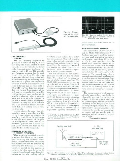
peak current or conduction angle. Fig.<br />
1 1 illustrates this point by showing the<br />
waveform obtained when a measure<br />
ment was made with the probe of the<br />
current in one rectifier of a bridge rec<br />
tifier circuit using solid-state rectifiers.<br />
This is an otherwise-difficult measure<br />
ment that could scarcely be made with<br />
out the probe.<br />
In determining the peak value of a<br />
waveform such as that shown in Fig.<br />
11, it is convenient to position the<br />
waveform vertically on the oscilloscope<br />
so that the lower corners of the pulse<br />
are equally-spaced about one of the<br />
horizontal graticule lines as shown. The<br />
peak pulse current can then be read<br />
from this line to the pulse peak.<br />
MEASURING DISTORTION<br />
IN CURRENT WAVEFORMS<br />
When working with audio frequencies<br />
it is often desirable to obtain informa<br />
tion concerning the harmonic distor<br />
tion in current waveforms. Frequently,<br />
this information can be obtained by<br />
measuring the distortion in a voltage<br />
waveform related to the current in<br />
question. In other cases, however, the<br />
current flows through a non-linear im<br />
pedance so that the resulting voltage<br />
Fig. 10. Close-up<br />
view of -dp- 456/4<br />
AC Current Probe.<br />
waveform is not suitable for a distor<br />
tion measurement. One such situation<br />
occurs when a signal current flows into<br />
the non-linear emitter circuit of a tran<br />
sistor. Here, the voltage waveform will<br />
not produce the needed distortion in<br />
formation, since the transistor opera<br />
tion is related to input current.<br />
For such instances the new current<br />
probe can be used with the -hp- Model<br />
3 02 A Wave Analyzer to obtain an<br />
analysis of the current waveform. The<br />
Model 3 02 A measures components up<br />
to 50 kc and has a narrow bandwidth<br />
which in transistor applications is bene<br />
ficial in reducing the effect of transistor<br />
noise on the measurement. Harmonic<br />
components 30 db or more below 1<br />
milliampere can ordinarily be meas<br />
ured with this arrangement. Distortion<br />
measurements can be made with negli<br />
gible contribution from the probe it<br />
self, a typical value for this contribu<br />
tion being 70 db below 1 0 milliamperes<br />
at 1 kc. Similarly, dc currents of the<br />
magnitudes typically encountered in<br />
*J. R. Petrak, "A New 20 CPS— 50 KC Wave<br />
Analyzer with High Selectivity and Simplified<br />
Tuning," Hewlett-Packard Journal, <strong>Volume</strong> 11,<br />
No. 1-2, Sept.-Oct., 1959.<br />
Transistor under test<br />
N<br />
Fig. 11. Current pulses in one leg of<br />
bridge type power rectifier circuit as<br />
measured with new probe.<br />
circuit work have little effect on the<br />
probe distortion.<br />
MICROAMPERE-RANGE CURRENTS<br />
The combination of the new probe<br />
and the Model 302A Harmonic Wave<br />
Analyzer can also be used for measur<br />
ing very small alternating currents in<br />
the frequency range from 20 cps to 50<br />
kc. On its most sensitive range the<br />
Model 302A measures voltages of 30<br />
microvolts full scale so that this range,<br />
when combined with the 1 mv/ma con<br />
version factor of the probe, permits<br />
currents below 30 microamperes to be<br />
measured. The method thus offers a<br />
means of measuring such small currents<br />
as the base current in transistors. Even<br />
though such currents are below the<br />
nominal noise level of the probe (50<br />
jita),, the measurement can still be made<br />
because of the filtering effect of the<br />
wave analyzer's selectivity character<br />
istic.<br />
The measurement of small currents<br />
with the wave analyzer can also be fa<br />
cilitated by the fact that the analyzer<br />
makes available for external use a sig<br />
nal (BFO output) which is the same in<br />
frequency as the frequency to which<br />
the analyzer input is tuned. Use of this<br />
signal to drive a circuit under test often<br />
eliminates the need for an external sig<br />
nal source and can greatly assist in<br />
measuring a signal current in the pres<br />
ence of noise.<br />
(Concluded on page 6)<br />
-hp- 302A<br />
WAVE ANALYZER<br />
Fig. distortion Probe can be used with -hp- 302 A Wave Analyzer to measure distortion in<br />
current waveforms or to measure small audio currents, as described in text.<br />
• 4 •<br />
© Copr. 1949-1998 Hewlett-Packard Co.