1960 , Volume v.11 n.11-12 , Issue July/August-1960
1960 , Volume v.11 n.11-12 , Issue July/August-1960
1960 , Volume v.11 n.11-12 , Issue July/August-1960

Create successful ePaper yourself
Turn your PDF publications into a flip-book with our unique Google optimized e-Paper software.
HEWLETT- PACKARD<br />
JOURNAL<br />
TECHNICAL INFORMATION FROM THE -hp- LABORATORIES<br />
JBLISHED BY THE HEWLETT-PACKARD COMPANY, 1501 PAGE MILL ROAD, PALO ALTO, CALIFORNIA<br />
A New Clip-On Oscilloscope/Voltmeter Probe<br />
For 25^-20 MC Current Measurements<br />
TWO years ago -hp- introduced a dc milliammeter<br />
that used a clip-on probe to couple to the conduc<br />
tor that carried the current to be measured. Because<br />
it merely clipped around the conductor and thus<br />
avoided the need for breaking the circuit, this probe<br />
changed the measurement of current from an incon<br />
venient and sometimes difficult measurement to an<br />
easy measurement. Later, this dc instrument was fol<br />
lowed by another clip-on probe type instrument<br />
which measured ac current in combination with the<br />
-hp- wide-band oscilloscope.<br />
The popularity of these clip-on probes for current<br />
measurements has now led to the development of a<br />
new and even more flexible clip-on probe— one that<br />
measures ac current in combination with any of a<br />
number of -hp- oscilloscopes and voltmeters. This<br />
new probe measures current over the full range of the<br />
frequencies most commonly used in typical work—<br />
25/V to 20 megacycles— and over an amplitude range<br />
from below £ milliampere up to 1 ampere rms. It<br />
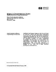
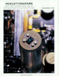
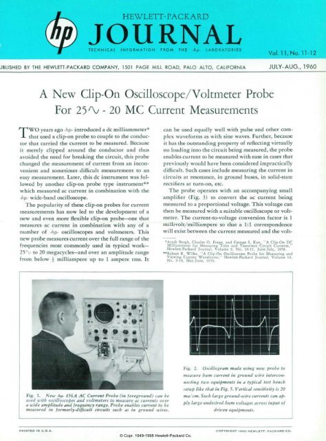
Fig. 1. New -hp- 456A AC Current Probe (in foreground) can be<br />
used with oscilloscopes and voltmeters to measure ac currents over<br />
a wide be and frequency range. Probe enables current to be<br />
measured in formerly-difficult circuits such as in ground wires.<br />
Vol. 11, No. 11-<strong>12</strong><br />
JULY- AUG., <strong>1960</strong><br />
can be used equally well with pulse and other com<br />
plex waveforms as with sine waves. Further, because<br />
it has the outstanding property of reflecting virtually<br />
no loading into the circuit being measured, the probe<br />
enables current to be measured with ease in cases that<br />
previously would have been considered impractically<br />
difficult. Such cases include measuring the current in<br />
circuits at resonance, in ground buses, in solid-state<br />
rectifiers at turn-on, etc.<br />
The probe operates with an accompanying small<br />
amplifier (Fig. 3) to convert the ac current being<br />
measured to a proportional voltage. This voltage can<br />
then be measured with a suitable oscilloscope or volt<br />
meter. The current-to-voltage conversion factor is 1<br />
millivolt/milliampere so that a 1:1 correspondence<br />
will exist between the current measured and the volt-<br />
•Arndt Bergh, Charles O. Forge, and George S. Kan, "A Clip-On DC<br />
Milliammeter for Measuring Tube and Transistor Circuit Currents,"<br />
Hewlett-Packard Journal, <strong>Volume</strong> 9, No. 10-11, June-<strong>July</strong>, 1958.<br />
"Robert R. Wilke, "A Clip-On Oscilloscope Probe for Measuring and<br />
Viewing Current Waveforms," Hewlett-Packard Journal, <strong>Volume</strong> 10,<br />
No. 9-10, May-June, 1959.<br />
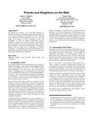
Fig. 2. Oscillogram made using new probe to<br />
measure hum current in ground wire intercon<br />
necting two equipments in a typical test bench<br />
setup like that in Fig. 5. Vertical sensitivity is 20<br />
ma/ cm. Such large ground-wire currents can ap<br />
ply large undesired hum voltages across input of<br />
driven equipments.<br />
PRINTED IN U.S.A. COPYRIGHT I960 HEWLETT- PACKARD CO.<br />
© Copr. 1949-1998 Hewlett-Packard Co.
Fig. 3. which current probe consists of clip-on head and transistorized amplifier which<br />
can be used with oscilloscope or ac voltmeter.<br />
age applied to the oscilloscope or volt<br />
meter. Current readings can thus be<br />
taken directly from the voltage cali<br />
brations on the oscilloscope or voltme<br />
ter. Table I presents a list of -hp- instru<br />
ments with which the probe can be<br />
used.<br />
LOW CIRCUIT LOADING<br />
Electrically, the probe consists of the<br />
secondary winding of a wide-range<br />
current transformer for which the con<br />
ductor being measured becomes a sin<br />
gle-turn primary. To accommodate the<br />
clip-on action, the secondary is wound<br />
on a split core which opens and closes<br />
with the probe jaws. The whole assem<br />
bly is magnetically and electrostatically<br />
shielded from external fields and elec<br />
trostatically shielded from the primary<br />
conductor.<br />
An extremely valuable feature of<br />
such a probe is that it can be designed<br />
to reflect very little impedance into the<br />
circuit being measured. For the new<br />
probe the loading reflected into the<br />
measured circuit is less than 50 milli-<br />
ohms in series with 0.05 microhenry.<br />
Because this loading is so small, currents<br />
can be measured in the formerly-diffi<br />
cult cases noted earlier such as in<br />
ground buses.<br />
The measurement of ground-wire<br />
currents, in fact, is probably consider<br />
ably more valuable than is generally<br />
realized. At power line frequencies cur-<br />
TABLE I<br />
-dp- INSTRUMENTS FOR USE<br />
WITH 456A AC CURRENT PROBE<br />
-hp-<br />
Voltmeters<br />
400D<br />
400H<br />
400L<br />
403A<br />
Wave Analyzer<br />
302A<br />
-hp-<br />
Oscilloscopes<br />
<strong>12</strong>0A<br />
<strong>12</strong>2 A<br />
130B<br />
150A<br />
160B<br />
170A<br />
rents of surprising magnitude can flow<br />
in the leads that interconnect the<br />
chassis of several equipments. This is<br />
true not only of unshielded ground<br />
wires where stray magnetic fields may<br />
induce the currents, but can also occur<br />
from a number of other causes. Fig. 5,<br />
for example, illustrates how the use of<br />
3 -prong type power cable plugs will<br />
transfer a significant portion of a volt<br />
age drop in a ground bus to the input<br />
terminals of an equipment. The current<br />
measured in a setup like that in Fig. 5<br />
is shown in Fig. 2 (front page). This<br />
current, with a peak amplitude of more<br />
than 50 ma, could easily cause a hum<br />
signal of 0.1 millivolt to be impressed<br />
at the input terminals of an equipment<br />
connected in the setup of Fig. 5.<br />
The source of currents like that in<br />
Fig. 2 can often be traced to other<br />
equipments and devices connected to<br />
the power line. Where such equipments<br />
have capacity, or sometimes leakage, to<br />
their frame or chassis and where the<br />
frame or chassis is grounded to the bus<br />
to which the third prong on a power<br />
OTHER EQUIPMENT SET-UP BEING TESTED<br />
POWER I<br />
LINE i l T<br />
¡"T I<br />
'> T<br />
10 100 % > 10MC 20MC<br />
FREO U E N C ï<br />
Fig. 6. Typical frequency response of -dp- Model 456 A Current Probe when operated<br />
into rated load.<br />
ment with which it is used. For cases<br />
where the probe is to be used with other<br />
equipment, the curve of Fig. 7 can be<br />
used to determine the resulting high<br />
frequency response.<br />
Figs. 6 and 7 both assume that the<br />
resistive portion of the load into which<br />
the probe amplifier is operated is 1 00 or<br />
more kilohms. Smaller load resistances<br />
can be used, however, with some loss<br />
in accuracy.<br />
Amplitude-wise, the probe calibra<br />
tion is adjusted at 1 kc to be accurate<br />
within ±\%. The frequency response<br />
is then sufficiently constant that overall<br />
accuracy remains within an additional<br />
± 1 % from a few hundred cycles to<br />
above a megacycle.<br />
FAST PULSE RESPONSE<br />
The wide bandwidth of the probe<br />
head and its amplifier gives the overall<br />
instrument a fast rise time of approxi<br />
mately 20 millimicroseconds and an<br />
otherwise accurate fast pulse response,<br />
as demonstrated by the oscillogram of<br />
Fig. 8. The rise time illustrated in Fig.<br />
8 approximates that of the faster wide<br />
band oscilloscopes and thus makes the<br />
probe very valuable in fast circuit ap<br />
plications. This value applies not only<br />
to the measurement of current but in<br />
+2-1<br />
0-<br />
-6-<br />
IMC 10MC<br />
some cases to the investigation of volt<br />
age, as discussed below.<br />
Where speed or rise time of the meas<br />
uring equipment is a factor, it is inter<br />
esting to note that the probe may give<br />
faster response time when used with a<br />
fast oscilloscope than is obtained when<br />
the oscilloscope is used in the usual way<br />
for voltage measurements. One com<br />
mon situation where this is true is<br />
where a measurement is to be made of<br />
the voltage rise time across a plate load<br />
resistor of some hundreds or more ohms.<br />
In such a case the capacity of some 10<br />
to 30 mmf added by the oscilloscope<br />
when making a voltage measurement<br />
will increase the time constant of the<br />
resultant R.C combination and slow the<br />
speed of measurement. A plate load re<br />
sistor of 1,000 ohms, for example, when<br />
shunted by 20 mmf has a 10-90% rise<br />
time of 44 millimicroseconds.<br />
The new current probe, on the other<br />
hand, can be used in this same situation<br />
by clipping to the "cold" end of a plate<br />
load resistor where the probe adds no<br />
effective capacity. In this case the probe<br />
rise time of 20 millimicroseconds, al<br />
though it may be modified somewhat<br />
by the rise time of the oscilloscope used,<br />
may still be significantly faster than the<br />
rise time obtained in a voltage meas<br />
urement.<br />
FREQUENCY<br />
30MC<br />
Fig. various load high frequency response of probe when used with various load<br />
capacities. Probe has been designed so that optimum frequency response occurs with<br />
25 mmf capacities typical of wide-band oscilloscopes.<br />
© Copr. 1949-1998 Hewlett-Packard Co.<br />
Fig. 8. Fast pulse response of current<br />
probe as displayed by -hp- 1 70 A wide-band<br />
oscilloscope. Sweep time is 0.05 ¡isec/cm,<br />
showing probe 10-90% rise time of 0.02<br />
fisec.<br />
Another case where the probe often<br />
proves superior to the voltage-across-<br />
resistance method of measuring current<br />
is demonstrated by the oscillograms in<br />
Fig. 9. These oscillograms show meas<br />
urements made of the current in the<br />
emitter circuit of a pulsed transistor.<br />
The upper oscillogram was made by in<br />
serting a 1-ohm resistance in the emit<br />
ter circuit and measuring the resulting<br />
voltage drop with the oscilloscope. The<br />
second oscillogram was made with the<br />
1-ohm resistance removed from the cir<br />
cuit and with the probe connected to<br />
give the current reading directly. In<br />
both cases the current scale is the same.<br />
If these two oscillograms are com<br />
pared, it will be seen that the voltage-<br />
derived measurement shows consider<br />
ably more overshoot as well as a current<br />
value about 10% lower than in the case<br />
where the current value was measured<br />
with the probe. The overshoot arises<br />
from the voltage drop occurring across<br />
the inductance of about % " of lead on<br />
the resistor. The 10% change in current<br />
occurs from the effect of the 1-ohm re<br />
sistor in the emitter circuit.<br />
(b)<br />
Fig. 9. Oscillograms contrasting pulse<br />
waveforms obtained in grounded-emitter<br />
transistor using two measurement tech<br />
niques. Upper trace shows voltage wave<br />
form across 1-ohm resistor with large<br />
overshoot produced by lead inductance.<br />
Lower trace shows more accurate current<br />
waveform obtained using new probe.
LOW FREQUENCY<br />
RESPONSE<br />
The low frequency amplitude re<br />
sponse, as indicated in Fig. 6, is such<br />
that the probe can be used to measure<br />
currents down to virtually the lowest<br />
audio frequencies, since the lower 3-db<br />
point is rated at 25 cps. This extended<br />
low frequency response has the addi<br />
tional value that it enables the probe<br />
to measure relatively long pulses with<br />
little resultant sag. In measuring recti<br />
fier currents at power line frequencies,<br />
however, there will be a moderate wave<br />
form distortion due to phase shift at<br />
60 or <strong>12</strong>0 cps. This distortion, though,<br />
does not prevent determination of the<br />
peak current or conduction angle. Fig.<br />
1 1 illustrates this point by showing the<br />
waveform obtained when a measure<br />
ment was made with the probe of the<br />
current in one rectifier of a bridge rec<br />
tifier circuit using solid-state rectifiers.<br />
This is an otherwise-difficult measure<br />
ment that could scarcely be made with<br />
out the probe.<br />
In determining the peak value of a<br />
waveform such as that shown in Fig.<br />
11, it is convenient to position the<br />
waveform vertically on the oscilloscope<br />
so that the lower corners of the pulse<br />
are equally-spaced about one of the<br />
horizontal graticule lines as shown. The<br />
peak pulse current can then be read<br />
from this line to the pulse peak.<br />
MEASURING DISTORTION<br />
IN CURRENT WAVEFORMS<br />
When working with audio frequencies<br />
it is often desirable to obtain informa<br />
tion concerning the harmonic distor<br />
tion in current waveforms. Frequently,<br />
this information can be obtained by<br />
measuring the distortion in a voltage<br />
waveform related to the current in<br />
question. In other cases, however, the<br />
current flows through a non-linear im<br />
pedance so that the resulting voltage<br />
Fig. 10. Close-up<br />
view of -dp- 456/4<br />
AC Current Probe.<br />
waveform is not suitable for a distor<br />
tion measurement. One such situation<br />
occurs when a signal current flows into<br />
the non-linear emitter circuit of a tran<br />
sistor. Here, the voltage waveform will<br />
not produce the needed distortion in<br />
formation, since the transistor opera<br />
tion is related to input current.<br />
For such instances the new current<br />
probe can be used with the -hp- Model<br />
3 02 A Wave Analyzer to obtain an<br />
analysis of the current waveform. The<br />
Model 3 02 A measures components up<br />
to 50 kc and has a narrow bandwidth<br />
which in transistor applications is bene<br />
ficial in reducing the effect of transistor<br />
noise on the measurement. Harmonic<br />
components 30 db or more below 1<br />
milliampere can ordinarily be meas<br />
ured with this arrangement. Distortion<br />
measurements can be made with negli<br />
gible contribution from the probe it<br />
self, a typical value for this contribu<br />
tion being 70 db below 1 0 milliamperes<br />
at 1 kc. Similarly, dc currents of the<br />
magnitudes typically encountered in<br />
*J. R. Petrak, "A New 20 CPS— 50 KC Wave<br />
Analyzer with High Selectivity and Simplified<br />
Tuning," Hewlett-Packard Journal, <strong>Volume</strong> 11,<br />
No. 1-2, Sept.-Oct., 1959.<br />
Transistor under test<br />
N<br />
Fig. 11. Current pulses in one leg of<br />
bridge type power rectifier circuit as<br />
measured with new probe.<br />
circuit work have little effect on the<br />
probe distortion.<br />
MICROAMPERE-RANGE CURRENTS<br />
The combination of the new probe<br />
and the Model 302A Harmonic Wave<br />
Analyzer can also be used for measur<br />
ing very small alternating currents in<br />
the frequency range from 20 cps to 50<br />
kc. On its most sensitive range the<br />
Model 302A measures voltages of 30<br />
microvolts full scale so that this range,<br />
when combined with the 1 mv/ma con<br />
version factor of the probe, permits<br />
currents below 30 microamperes to be<br />
measured. The method thus offers a<br />
means of measuring such small currents<br />
as the base current in transistors. Even<br />
though such currents are below the<br />
nominal noise level of the probe (50<br />
jita),, the measurement can still be made<br />
because of the filtering effect of the<br />
wave analyzer's selectivity character<br />
istic.<br />
The measurement of small currents<br />
with the wave analyzer can also be fa<br />
cilitated by the fact that the analyzer<br />
makes available for external use a sig<br />
nal (BFO output) which is the same in<br />
frequency as the frequency to which<br />
the analyzer input is tuned. Use of this<br />
signal to drive a circuit under test often<br />
eliminates the need for an external sig<br />
nal source and can greatly assist in<br />
measuring a signal current in the pres<br />
ence of noise.<br />
(Concluded on page 6)<br />
-hp- 302A<br />
WAVE ANALYZER<br />
Fig. distortion Probe can be used with -hp- 302 A Wave Analyzer to measure distortion in<br />
current waveforms or to measure small audio currents, as described in text.<br />
• 4 •<br />
© Copr. 1949-1998 Hewlett-Packard Co.
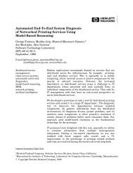
THE VALUE OF AC CURRENT MEASUREMENTS<br />
Fig. 1. Oscillogram of plate voltage<br />
(upper trace) and plate current (lower<br />
trace) of Class C-pentode measured us<br />
ing -dp- 456/4 current probe with dual-<br />
channel oscilloscope. Note sine-wave<br />
current component along base line of<br />
lower trace.<br />
Fig. 2. Oscillogram showing screen<br />
current (upper trace) and plate current<br />
(lower trate) of same tube as in Pig. 1<br />
measured using two 456 A current probes<br />
with dual-channel oscilloscope. Upper<br />
trace has twice the sensitivity of lower<br />
trace.<br />
Experience with the -hp- clip-on<br />
current probes has frequently and<br />
consistently shown that the conven<br />
ience with which these probes enable<br />
current to be measured leads to infor<br />
mation that would not otherwise be<br />
obtained. A case in point is demon<br />
strated by the accompanying oscillo-<br />
grams. The upper waveform in the<br />
first Oscillogram shows the plate<br />
voltage waveform on a pentode operat<br />
ing in a class C stage. From all appear<br />
ances this waveform is conventional<br />
and does not indicate much about the<br />
operating conditions of the tube. Im<br />
mediately below the plate voltage<br />
waveform in Fig. 1, however, is the<br />
plate current waveform as measured<br />
with the new Model 45 6 A Current<br />
Probe and displayed by an -hp- Model<br />
16 OB dual-trace oscilloscope. This<br />
plate current waveform shows at once<br />
that the plate is being driven below<br />
the knee of the plate current-plate<br />
voltage characteristic. At the current<br />
peaks the plate current is notched, in<br />
dicating that the plate is bottoming<br />
and thus losing current to the screen.<br />
It is also interesting to note that the<br />
current base line, instead of showing<br />
zero current, shows a sine-wave cur<br />
rent component which is the current<br />
chat flows mainly through the plate<br />
capacitance of the tube.<br />
In Fig. 2 the upper trace shows the<br />
screen-grid current, while the lower<br />
trace again shows the plate current for<br />
the same tube as in Fig. 1. The oscil-<br />
logram was made by using two of the<br />
current probes simultaneously. For<br />
convenience the screen current is<br />
shown at twice the sensitivity of the<br />
plate current. It is readily apparent<br />
that the lost pulses of plate current<br />
are drawn by the screen. The screen<br />
also shows a sine-wave component of<br />
capacitive current.<br />
CURRENT SUMMING<br />
AND EQUALIZING<br />
Since the probe is effectively a cur<br />
rent transformer, it has the property<br />
that it will algebraically sum the in<br />
stantaneous value of the currents in<br />
two or more conductors it may be<br />
clipped around. This property makes<br />
the probe a valuable and easily-applied<br />
tool in applications in which it is de<br />
sired to equalize or balance ac cur<br />
rents. In the case involving the class C<br />
stage described above, for example, it<br />
is possible to use this summing prop<br />
erty to examine the plate current<br />
pulses exclusive of the current com<br />
ponent flowing through the capacity<br />
of the tube. This would then easily<br />
permit the angle of plate current flow<br />
to be measured. Fig. 3 shows the re<br />
sult when this is done. In Fig. 3 the<br />
same plate current pulses as in Fig. 2<br />
are shown, except at twice the display<br />
sensitivity. In Fig. 2 the capacitive<br />
component is present, while in Fig. 3<br />
this component has been bucked out.<br />
The method used to obtain the buck<br />
ing current is indicated in Fig. 4. The<br />
probe was clipped around the plate<br />
lead of the tube, but at the same time<br />
a lead from an external variable ca<br />
pacitor was connected to the plate<br />
lead and passed through the probe as<br />
© Copr. 1949-1998 Hewlett-Packard Co.<br />
Fig. 3. Same plate current as in fig. 2<br />
but with capacitive component bucked<br />
out using technique indicated in Fig. 4<br />
and described in text.<br />
-hp- 456A<br />
PROBE HUD<br />
Fig. 4. Arrangement used to buck out<br />
capacitive component of plate current.<br />
shown. By suitably adjusting the vari<br />
able capacitor, a capacitive current<br />
equal but opposite to the capacitive<br />
current flowing at the plate can be ap<br />
plied to the probe. For display pur<br />
poses the tube's electron current is<br />
thus separated from the capacitive<br />
current.<br />
It is abo interesting to note that<br />
the arrangement shown in Fig. 4 pro<br />
vides a dynamic measure of the out<br />
put capacity of the tube. This occurs<br />
because the final setting of the varia<br />
ble capacitor should be equal to the<br />
tube output capacity.<br />
The probe is valuable in a number<br />
of other current-equalizing applica<br />
tions. Especially common among these<br />
are equalizing the input and output<br />
currents in push-pull and balanced<br />
circuits in both transistor and tube<br />
applications.
Fig. 13. -hp- Model 456A Current probe<br />
as used with -dp- Model 400D VTVM.<br />
HIGHER SENSITIVITIES<br />
Under some if not many circum<br />
stances, the basic 1 mv/ma sensitivity<br />
of the probe can be increased two or<br />
more times by looping additional turns<br />
of the conductor being measured<br />
through the probe head. Looping turns<br />
in this way will increase the probe sen<br />
sitivity in proportion to the number of<br />
times the conductor passes through the<br />
head and will do so without increasing<br />
the nominal noise level of the probe.<br />
The main considerations involved in<br />
this method of increasing sensitivity<br />
are the additional self -inductance that<br />
the looping causes in the primary con<br />
ductor and the effect of this self-in<br />
ductance in combination with the loop-<br />
to-loop capacitance of the conductor.<br />
This combination can result in a reson<br />
ance in the low megacycle region.<br />
Where this resonance is not a factor,<br />
however, and where physical factors<br />
permit, as many as 10 turns can be<br />
used in this way.<br />
INSULATION CONSIDERATIONS<br />
The exterior surfaces of the probe<br />
head are molded from an electrically-<br />
insulating plastic so as to preclude the<br />
possibility of shock when the probe is<br />
clipped on a conductor that is at an<br />
ac and/or dc voltage. However, the in<br />
terior surfaces of the aperture that re<br />
ceives the conductor to be measured<br />
necessarily consist of metallic parts to<br />
achieve the desired electrostatic and<br />
magnetic shielding for the probe head.<br />
These parts are electrically connected<br />
to the low terminal of the plug that<br />
interconnects the probe to its compan<br />
ion instrument. Since insulating these<br />
shield parts would seriously diminish<br />
the electrical and mechanical usefulness<br />
of the probe, it has been deemed more<br />
advantageous to the user to arrange the<br />
probe to rely on the insulation of the<br />
conductor being measured to electri<br />
cally isolate the probe from any voltage<br />
on the conductor. Hence the probe<br />
should be used only with adequately in<br />
sulated conductors when a voltage<br />
exists on the conductor. Normally, this<br />
requirement imposes no serious incon<br />
venience, since conductors with signifi<br />
cant voltage will often already be in<br />
sulated. Where bare conductors off<br />
ground are encountered, it is usually<br />
adequate to insulate a portion of the<br />
conductor by a turn or two of electrical<br />
insulating tape. It is also often conven<br />
ient merely to clip the probe around a<br />
small insulated composition resistor<br />
where one is in the circuit.<br />
In addition to the conductor insula<br />
tion consideration, the low side of the<br />
double plug on the output of the probe<br />
amplifier should for personnel safety be<br />
connected only to the equipment termi<br />
nal that is solidly grounded to a power<br />
line system ground.<br />
GROUND LEAD<br />
The probe head is provided with a<br />
detachable ground lead (Fig. 10) which<br />
is occasionally useful in fast circuit<br />
work. If the oscilloscope used with the<br />
probe has significant response at 1 5 me<br />
and higher and the circuit under meas-<br />
1 1 f < i r > - n i r - i t - K i c o n o v r r T r i f f \ i a r a f f C Q U K O â € ”<br />
cies, it is desirable to use the ground<br />
lead to connect the probe head to the<br />
chassis under test. This will short stray<br />
capacities and minimize undesired spur<br />
ious responses that may be formed with<br />
such capacities. At these frequencies<br />
solid grounding between the oscillo<br />
scope, probe amplifier chassis, and<br />
chassis under test are also generally<br />
necessary.<br />
BATTERY OR<br />
POWER LINE<br />
OPERATION<br />
The amplifier for the probe has been<br />
designed as a transistorized amplifier to<br />
achieve the advantages of long life,<br />
small size, and light weight. Transis<br />
torization has also made it practical to<br />
arrange the amplifier to be battery-op<br />
erated, thereby achieving portability as<br />
well as a lower selling price, although<br />
the amplifier is also available in an ac-<br />
operated version. The two versions are<br />
identical in size and appearance.<br />
Battery operation also has perform<br />
ance advantages because the residual<br />
noise level of the amplifier is somewhat<br />
lower in the battery-operated version.<br />
GENERAL<br />
The probe has several other conven<br />
iences which are worthy of mention.<br />
As a convenience in pulse work, the<br />
head is marked with an arrow to relate<br />
the direction of conventional current<br />
© Copr. 1949-1998 Hewlett-Packard Co.<br />
flow in the conductor being measured<br />
to the resulting positive voltage at the<br />
probe output terminals. The probe aper<br />
ture is large enough (5/32" diameter)<br />
to accept most conductors usually<br />
found in electronics work. Head shield<br />
ing from external magnetic fields is<br />
such that these are seldom troublesome,<br />
but in any case a check can be made<br />
merely by holding the probe with closed<br />
jaws in the region of interest to see if<br />
a reading occurs.<br />
Electrically, the probe has a capacity<br />
of only about 4 mmf to the conductor<br />
measured and consequently only a<br />
slight conductor voltage effect of 0.03<br />
ma/volt-megacycle. In most cases this<br />
is too small to be noticed. Similarly, the<br />
effect of dc in the measured conductor<br />
is normally insignificant, since half an<br />
ampere of dc at the lowest audio fre<br />
quencies or several amperes at higher<br />
frequencies are required before an effect<br />
is noticeable.<br />
ACKNOWLEDGMENT<br />
The design group for the new probe<br />
was headed by George S. Kan and in<br />
cluded Hudson F. Grotzinger, who per<br />
formed the mechanical design, in<br />
addition to the undersigned.<br />
—Charles O. Forge<br />
SPECIFICATIONS<br />
-/ip- MODEL 456A<br />
AC CURRENT PROBE<br />
Sensitivity: 1 mv/ma ± 1% at 1 kc.<br />
Frequency Response: ± 2%, 100 cps to 3 me.<br />
± 5%, 60 cps to 4 me.<br />
-3 db, 25 cps to 20 me.<br />
Pulse Response: Rise time is less than 20 nano<br />
seconds; sag is less than 16% per milli<br />
second.<br />
Maximum Input: 1 amp rms; 1.5 amp peak.<br />
100 ma above 5 me.<br />
Effect of DC Current: No appreciable effect on<br />
sensitivity and distortion from dc current up<br />
to 0.5 amp.<br />
Input Impedance: (Impedance added in series<br />
with measured wire by probe). Less than 50<br />
milliohms in series with .05 /¿h. (This is ap<br />
proximately the inductance of 1V2 in. of<br />
hookup wire).<br />
Probe Shunt Capacity: Approximately 4 pf<br />
added from wire to ground.<br />
Distortion at 1 KC: For '/2 amp input at least<br />
50 db down. For 10 ma input at least 70 db<br />
down.<br />
Equivalent Input Noise: Less than 50 /¿a rms<br />
(100 /¿a when ac powered).<br />
Output Impedance: 220 ohms at 1 kc. Approxi<br />
mately -f- 1 v dc component. Should work<br />
into load of not less than 100,000 ohms<br />
shunted by approximately 25 pf.<br />
Power: Battery-operated with mercury-cell type<br />
batteries furnished; battery life is approxi<br />
mately 400 hours. Ac power supply optional<br />
at extra cost, 115'230 v ± 10%, 50 to 1000<br />
cps; approx. 1 watt.<br />
Weight: Net 3 Ibs.<br />
Dimensions: 5 in. wide, 6 in. deep, 1 T/2 in.<br />
high. Probe cable is 5 ft. long; output cable<br />
is 2 ft. long and terminated with a dual<br />
banana plug.<br />
Price: -hp- Model 456A with batteries, $190.00.<br />
-np- Model 456A with ac supply (456A-95A)<br />
installed in lieu of batteries, $210.00.<br />
Prices f.o.b. Palo Alto, California<br />
Data Subject to change without notice