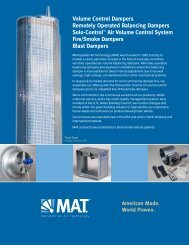
Volume Control Dampers Remotely Operated Balancing Dampers ...
Volume Control Dampers Remotely Operated Balancing Dampers ...
Volume Control Dampers Remotely Operated Balancing Dampers ...

You also want an ePaper? Increase the reach of your titles
YUMPU automatically turns print PDFs into web optimized ePapers that Google loves.
<strong>Volume</strong> <strong>Control</strong> <strong>Dampers</strong><br />
<strong>Remotely</strong> <strong>Operated</strong> <strong>Balancing</strong> <strong>Dampers</strong><br />
Solo-<strong>Control</strong> TM<br />
Air <strong>Volume</strong> <strong>Control</strong> System<br />
Fire/Smoke <strong>Dampers</strong><br />
Blast <strong>Dampers</strong><br />
Metropolitan Air Technology (MAT) was founded in 1992 to bring to<br />
market a newly patented concept in the field of manually controlled,<br />
remotely operated air volume balancing dampers. <strong>Remotely</strong> operated<br />
balancing dampers are required in installations where the balancing<br />
damper is inaccessible for direct manual adjustment due to drywall<br />
ceilings, high ceilings, or interference from other mechanical systems.<br />
In response to market demand for a full commercial damper line, we<br />
expanded our offering with the introduction of a line of volume control<br />
dampers and a UL classified line of fire/smoke dampers.<br />
We’re committed to the continuous evolution of our products, stellar<br />
customer service, and a top-notch quality management system. As a<br />
member of the U.S. Green Building Council, we monitor changes and<br />
trends within the green building industry to help identify our customer’s<br />
future needs and enhance our product development efforts.<br />
Our products are manufactured in the USA and sold in North America and<br />
international markets.<br />
MAT products are protected by US and International patents.<br />
Trump Tower<br />
Chicago, Illinois, USA<br />
American Made.<br />
World Proven.
Fire <strong>Dampers</strong><br />
© 2012 Metropolitan Air Technology. All rights reserved. 7/12<br />
American Made. World Proven.<br />
Fire, Smoke & Radiation<br />
<strong>Dampers</strong><br />
Model<br />
FD-SALB Curtain Fire Damper/Static P-1<br />
FD-SB Curtain Fire Damper/Static P-2<br />
FD-SC Curtain Fire Damper/Static P-3<br />
FDD-SALB Curtain Fire Damper/Dynamic/Static P-4<br />
FDD-SAB Curtain Fire Damper/Dynamic/Static P-5<br />
FDD-SC Curtain Fire Damper/Dynamic/Static P-6<br />
FD-ALB Curtain Fire Damper/Static P-7<br />
FD-B Curtain Fire Damper/Static P-8<br />
FD-C Curtain Fire Damper/Static P-9<br />
FDD-ALB Curtain Fire Damper/Dynamic/Static P-10<br />
FDD-B Curtain Fire Damper/Dynamic/Static P-11<br />
FDD-C Curtain Fire Damper/Dynamic/Static P-12<br />
FD-ASL (OW) Slimline Curtain Fire Damper/Static P-13<br />
FD-BSL Slimline Curtain Fire Damper/Static P-14<br />
FD-AUSL Ultra Slimline Curtain Fire Damper/Static P-15<br />
FDD-ASL (OW) Slimline Curtain Fire Damper/Dynamic/Static P-16<br />
FDD-BSL Slimline Curtain Fire Damper/Dynamic/Static P-17<br />
FD-ACMH Curtain Fire Damper-Caulk Sealed/Static P-18<br />
FD-ACHP Curtain Fire Damper-Welded/Static P-19<br />
FD-SAVG Curtain Fire Damper-Behind Grille/Static P-20<br />
FDD-SAHG Curtain Fire Damper/Dynamic/Static P-21<br />
FDD-SAVG Curtain Fire Damper/Dynamic/Static P-22<br />
FD-SAHG Curtain Fire Damper-Behind Grille/Static P-23<br />
FD-AOW Curtain Fire Damper/Static P-24<br />
FDD-AOW Curtain Fire Damper/Dynamic P-25<br />
FD-R (Static), FDD-R Dynamic True Round P-27<br />
FD 110-3V (OW-) (-CR) Multi Blade/Static P-28<br />
FD-160-AF (OW-) (-CR) Multi Blade/Static P-29<br />
FDD 110-3V (OW-) (-CR) Multi Blade/Dynamic/Static P-30<br />
FDD-160-AF (OW-) (-CR) Multi Blade/Dynamic/Static P-31<br />
FD-A-3V Curtain Fire Damper/Static P-32<br />
FD w/ Micro Switch for Status <strong>Control</strong> or Shut Off P-33<br />
ANG-Framed Retaining Angle Installation P-34<br />
General Installation Instructions P-35<br />
Out of Wall/Partition Installation Instructions P-36<br />
FD-R & FDD-R Installation Instructions P-37<br />
Supplemental Installation Instructions P-38<br />
Support Mullions Installation Instructions P-39<br />
Combination Fire/Smoke <strong>Dampers</strong><br />
F/S-3V-I & F/S-3V-3-I 3V Blade P-40<br />
F/S-3V-II & F/S-3V-3-II 3V Blade P-41<br />
F/S-AF-I & F/S-AF-3-I Airfoil Blade P-42<br />
F/S-AF-II & F/S-AF-3-II Airfoil Blade P-43<br />
F/S-RD-I True Round P-44<br />
F/S-RD-II True Round P-45<br />
F/S-3V-FA-I 3V Blade-Front Access P-46<br />
F/S-3V-FA-II 3V Blade-Front Access P-47<br />
F/S-3V-OW-I 3V Blade-Out of Wall P-48<br />
F/S-3V-OW-II 3V Blade-Out of Wall P-49<br />
F/S-AF-OW-I Airfoil Blade-Out of Wall P-50<br />
F/S-AF-OW-II Airfoil Blade-Out of Wall P-51<br />
F/S-AF-FA-I Airfoil Blade-Front Access P-52<br />
F/S-AF-FA-II Airfoil Blade-Front Access P-53<br />
F/S-3V-CR-I Corridor Damper P-54
Combination Fire/Smoke <strong>Dampers</strong> (continued)<br />
F/S-3V-CR-II Corridor Damper P-55<br />
Basic Installation Instructions P-56<br />
Out of Wall Installation Instructions P-57<br />
F/S-RD Installation Instructions P-58<br />
F/S-3V-CR-I (II) Installation Instructions P-59<br />
Model ANG-RetainingAngles P-60<br />
STO/R-Single Thermostat Operator Release P-61<br />
DTO/R-Double Thermostat Operator Release P-62<br />
EFL-Electric Fuse Link P-63<br />
PFL-Pneumatic Fuse Link P-64<br />
M/S Micro Switch Package P-65<br />
RCB-Remote <strong>Control</strong> Box P-66<br />
Motor/Actuators P-67<br />
Smoke Detectors P-68, 68B, 68C<br />
Supplemental Installation Instructions P-69<br />
Damper Enclosures & Transitions P-70<br />
Damper Operators P-71<br />
Support Mullions Installation Instructions P-72<br />
Typical Motor Mount Locations P-73<br />
Duct Mounted Smoke Detector Detail P-74<br />
Actuators & Jackshafting P-75<br />
Smoke Detectors Installation Instructions P-76<br />
Smoke <strong>Dampers</strong><br />
S-3V-I 3V Blade P-77<br />
S-3V-II 3V Blade P-78<br />
S-AF-I Airfoil Blade P-79<br />
S-AF-II Airfoil Blade P-80<br />
S-RD-I True Round P-81<br />
S-RD-II True Round P-82<br />
M/S Micro Switch P-83<br />
RCB-1, 2, 3, 4 Remote <strong>Control</strong> Box P-84<br />
Basic Installation Instructions P-85<br />
Actuators & Jackshafting P-86<br />
<strong>Dampers</strong> Enclosures & Transitions P-87<br />
Smoke Damper Operators P-88<br />
Motor/Actuators P-89<br />
Radiation <strong>Dampers</strong><br />
C-RD & C-RD-A Ceiling Damper Round P-90<br />
C-RD-T & C-RD-A/T Ceiling Damper Square & Round P-91<br />
C-S/R & C-S/R-A Ceiling Damper Square & Rectangular P-92<br />
C-S/R-HC & C-S/R-HC-A Ceiling Damper Square & Rectangular P-93<br />
C/FS (B) (X) Ceiling Damper Square & Rectangular P-94<br />
C/FSR-1 & (-2) Ceiling Damper Square & Round P-95<br />
C/FS-2F Ceiling Damper Square & Rectangular P-96<br />
C/D-P Ceiling Damper Square & Rectangular P-97<br />
CK-2000-1 & (1B) Thermal Blanket P-98<br />
Applications P-99<br />
Basic Installation Instructions P-100<br />
Wood-Framed Joist w/Gypsum Ceiling P-101<br />
Life Safety Inspection-Test & Maintenance P-102<br />
Agency Listings<br />
American Made. World Proven.<br />
UL Certificate - Ceiling Radiation Damper P-103<br />
UL Certificate - Fire/Smoke Damper P-105<br />
© 2012 Metropolitan Air Technology. All rights reserved. 7/12
American Made. World Proven.<br />
Due to continuing research, MAT reserves the right to change specifications without notice.<br />
FD-SA<br />
Model FD-SA Curtain Fire Damper<br />
UL 555 Classified 1-1/2 and 3 hours for use in static systems<br />
6235 South Oak Park Avenue Chicago, IL 60638 USA Represented by:<br />
Toll free: 800.585.7686 +1.708.552.4040<br />
Fax: +1.708.594.0396 www.metairtech.com<br />
Application<br />
• The Model FD-SA is UL Classified for installation in walls, floors, and<br />
partitions with a fire rating of less than 3 hours.<br />
• This damper may be installed vertically or horizontally in static HVAC<br />
systems that automatically shut down in the event of fire. (See optional<br />
3 hr rating)<br />
Standard Construction<br />
• Frame: 12” Roll formed Frame - Galvanized Steel - Integral Sleeve<br />
• Blades: Low Profile Roll Formed - Galvanized Steel<br />
• Closure Springs (horizontal models only): Stainless Steel constant force<br />
coil<br />
• Fusible Link - UL-33: UL Classified 165°F (Standard), 212°F (Optional)<br />
• <strong>Dampers</strong> are furnished approximate to the duct dimensions provided,<br />
unless otherwise noted<br />
Model FD-SALB meets or complies with the following as a fire damper:<br />
• All major building codes, including IBC/ICC International Code<br />
• UL 555 Classified 1-1/2 and 3 Hour - File #R27198<br />
• NFPA - 90A, 80<br />
Sizes (duct) 1-1/2 Hour<br />
Min. V or H 6” X 6”, 152mm X 152mm<br />
*Max. Vertical 96”W X 96”H, 2438mm X 2438mm<br />
*Max. Horizontal 80”W X 40”H, 2032mmX 1016mm<br />
*May consist of multi-sections<br />
Sizes (duct) 3 Hour<br />
Min. V or H 6” X 6”, 152mm X 152mm<br />
*Max. Vertical 80”W X 40”H, 2032mm X 1016mm<br />
*Max. Horizontal 80”W X 40”H, 2032mm X 1016mm<br />
*May consist of multi-sections<br />
Options<br />
• Retaining Angles<br />
• One Side<br />
• Both Sides<br />
• 3 Hour Rating<br />
• Mounting<br />
• Horizontal<br />
• Vertical<br />
Note<br />
Refer to installation instructions for required opening in fire rated barrier.<br />
© 2012 Metropolitan Air Technology. All rights reserved. 7/12 P-1 Rev 7
American Made. World Proven.<br />
Model FD-SB Curtain Fire Damper<br />
UL 555 Classified 1-1/2 and 3 hours for use in static systems<br />
Application<br />
• The Model FD-SB is UL Classified for installation in walls, floors, and<br />
partitions with a fire rating of less than 3 hours.<br />
• May be installed vertically or horizontally in static HVAC systems that<br />
automatically shut down in the event of fire. (See optional 3 hr rating)<br />
Standard Construction<br />
• Frame: 12” Roll formed Frame - Galvanized Steel - Integral Sleeve<br />
• Blades: Low Profile Roll Formed - Galvanized Steel<br />
• Closure Springs (horizontal models only): Stainless Steel constant force<br />
coil<br />
• Fusible Link - UL-33: UL Classified 165°F (Standard), 212°F (Optional)<br />
• <strong>Dampers</strong> are furnished approximate to the duct dimensions provided,<br />
unless otherwise noted<br />
Model FD-SB meets or complies with the following as a fire damper:<br />
• All major building codes, including IBC/ICC International Code<br />
• UL 555 Classified 1-1/2 and 3 Hour - File #R27198<br />
• NFPA - 90A, 80<br />
Sizes (duct) 1-1/2 Hour<br />
Min. V or H 6” X 4”, 152mm X 101mm<br />
*Max. Vertical 96”W X 91”H, 2438mm X 2311mm<br />
*Max. Horizontal 80”W X 36”H, 2032mmX 914mm<br />
*May consist of multi-sections<br />
Sizes (duct) 3 Hour<br />
Min. V or H 6” X 4”, 152mm X 101mm<br />
*Max. Vertical 80”W X 36”H, 2032mm X 914mm<br />
*Max. Horizontal 80”W X 36”H, 2032mmX 914mm<br />
*May consist of multi-sections<br />
Options<br />
• Retaining Angles<br />
• One Side<br />
• Both Sides<br />
• 3 Hour Rating<br />
• Mounting<br />
• Horizontal<br />
• Vertical<br />
Due to continuing research, MAT reserves the right to change specifications without notice.<br />
FD-SB<br />
Represented by: 6235 South Oak Park Avenue Chicago, IL 60638 USA<br />
Toll free: 800.585.7686 +1.708.552.4040<br />
Fax: +1.708.594.0396 www.metairtech.com<br />
P-2 Rev5 © 2012 Metropolitan Air Technology. All rights reserved. 7/12
FD-SB<br />
American Made. World Proven.<br />
Model FD-SB Curtain Fire Damper Size Chart<br />
Horizontal and vertical 1-1/2 and 3 hour<br />
6235 South Oak Park Avenue Chicago, IL 60638 USA Represented by:<br />
Toll free: 800.585.7686 +1.708.552.4040<br />
Fax: +1.708.594.0396 www.metairtech.com<br />
Xx<br />
© 2012 Metropolitan Air Technology. All rights reserved. 7/12 P-2b
Options<br />
• 3 Hour Rating<br />
• Retaining Angles<br />
• One Side<br />
• Both Sides<br />
• Taped & Sealed Transition for Medium Pressure<br />
System<br />
• Caulked & Sealed Damper Frame<br />
Note<br />
Refer to installation instructions for required<br />
opening in fire rated barrier.<br />
American Made. World Proven.<br />
Due to continuing research, MAT reserves the right to change specifications without notice.<br />
FD-SC<br />
Model FD-SC Curtain Fire Damper<br />
UL 555 Classified 1-1/2 and 3 hours for use in static systems<br />
Application<br />
• The Model FD-SC is UL Classified for installation in walls, floors, and<br />
partitions with a fire rating of less than 3 hours.<br />
• This damper must be installed vertically or horizontally in static HVAC<br />
systems that automatically shut down in the event of fire. (See optional<br />
3 hr rating)<br />
Standard Construction<br />
• Frame: 12” Roll formed Type C Frame - Galvanized Steel - Integral<br />
Sleeve. See duct transition options on next page<br />
• Blades: Low Profile Roll Formed - Galvanized Steel 100% Free Area<br />
• Closure Springs (horizontal models only): Stainless Steel constant<br />
force coil<br />
• Fusible Link - UL-33: UL Classified 165°F (Standard), 212°F (Optional)<br />
• <strong>Dampers</strong> are furnished approximate to the duct dimensions provided,<br />
unless otherwise noted<br />
• <strong>Dampers</strong> are furnished approximately 1/4” undersized to the duct<br />
dimensions provided, unless otherwise noted.<br />
Model FD-SC meets or complies with the following as a fire damper:<br />
• All major building codes, including IBC/ICC International Code<br />
• UL 555 Classified 1-1/2 and 3 Hour - File #R27198<br />
• NFPA - 90A, 80<br />
Sizes (duct) 1-1/2 & 3 Hour<br />
Rectangular or Oval<br />
Min. V or H 4” X 3”, 102mm X 76mm<br />
*Max. Vertical 47”W X 43”H, 1194mm X 1092mm<br />
*Max. Horizontal 39”W X 35”H, 991mmX 889mm<br />
Round<br />
Min. V or H 3”Diameter, 76mm<br />
*Max. Vertical 43” Diameter, 1092mm<br />
*Max. Horizontal 35” Diameter, 889mm<br />
*See Chart for Overall Sizes<br />
Represented by: 6235 South Oak Park Avenue Chicago, IL 60638 USA<br />
Toll free: 800.585.7686 +1.708.552.4040<br />
Fax: +1.708.594.0396 www.metairtech.com<br />
P-3 Rev 6 © 2012 Metropolitan Air Technology. All rights reserved. 7/12
Transitions for Type C Frames<br />
FD-SC<br />
6235 South Oak Park Avenue Chicago, IL 60638 USA Represented by:<br />
Toll free: 800.585.7686 +1.708.552.4040<br />
Fax: +1.708.594.0396 www.metairtech.com<br />
American Made. World Proven.<br />
Model FD-SC Curtain Fire Damper Size Chart<br />
Horizontal and vertical 1-1/2 and 3 hour<br />
© 2012 Metropolitan Air Technology. All rights reserved. 7/12 P-3b Rev 6
American Made. World Proven.<br />
Due to continuing research, MAT reserves the right to change specifications without notice.<br />
FDD-SA<br />
Model FDD-SA Curtain Fire Damper<br />
UL 555 Classified 1-1/2 and 3 hours for use in dynamic or static systems<br />
Application<br />
• The Model FDD-SA is UL Classified for installation in walls, floors, and<br />
partitions with a fire rating of less than 3 hours.<br />
• This damper may be installed vertically or horizontally in dynamic HVAC<br />
systems that continue to run in the event of fire. Also approved for<br />
static systems. (See optional 3 hour rating)<br />
Standard Construction<br />
• Frame: 12” Roll formed Frame - Galvanized Steel - Integral Sleeve<br />
• Blades: Low Profile Roll Formed - Galvanized Steel<br />
• Closure Springs: Stainless Steel constant force coil<br />
• Fusible Link - UL-33: UL Classified 165°F (Standard), 212°F (Optional)<br />
• Maximum Velocity: 2000 FPM (10.2 M/S)<br />
• Maximum Pressure: 4” WG (1KPA)<br />
• <strong>Dampers</strong> are furnished approximate to the duct dimensions provided,<br />
unless otherwise noted<br />
Model FDD-SA meets or complies with the following as a fire damper:<br />
• All major building codes, including IBC/ICC International Code<br />
• UL 555 Classified 1-1/2 and 3 Hour - File #R27198<br />
• NFPA - 90A, 80<br />
Sizes (duct) 1-1/2 & 3 Hour<br />
Min. V or H 6” X 6”, 152mm X 152mm<br />
*Max. Vertical 72”W X 36”H, 1829mm X 914mm or 36”W X 72”H,<br />
914mm X 1829mm<br />
*Max Horizontal 36”W X 36”H, 914mm X 914mm<br />
*May consist of multi-sections<br />
Options<br />
• Retaining Angles<br />
• One Side<br />
• Both Sides<br />
• 3 Hour Rating<br />
• Mounting<br />
• Horizontal<br />
• Vertical<br />
Note<br />
Refer to installation instructions for required opening in fire rated barrier.<br />
Represented by: 6235 South Oak Park Avenue Chicago, IL 60638 USA<br />
Toll free: 800.585.7686 +1.708.552.4040<br />
Fax: +1.708.594.0396 www.metairtech.com<br />
P-4 Rev 7 © 2012 Metropolitan Air Technology. All rights reserved. 7/12
American Made. World Proven.<br />
Due to continuing research, MAT reserves the right to change specifications without notice.<br />
FDD-SB<br />
Model FDD-SB Curtain Fire Damper<br />
UL 555 Classified 1-1/2 and 3 hours for use in dynamic or static systems<br />
6235 South Oak Park Avenue Chicago, IL 60638 USA Represented by:<br />
Toll free: 800.585.7686 +1.708.552.4040<br />
Fax: +1.708.594.0396 www.metairtech.com<br />
Application<br />
• The Model FDD-SB is UL Classified for installation in walls, floors, and<br />
partitions with a fire rating of less than 3 hours.<br />
• This damper may be installed vertically or horizontally in dynamic HVAC<br />
systems that continue to run in the event of fire. Also approved for<br />
static systems (See optional 3 hr rating)<br />
Standard Construction<br />
• Frame: 12” Roll formed Frame - Galvanized Steel - Integral Sleeve<br />
• Blades: Low Profile Roll Formed - Galvanized Steel<br />
• Closure Springs: Stainless Steel constant force coil<br />
• Fusible Link - UL-33: UL Classified 165°F (Standard), 212°F (Optional)<br />
• Maximum Velocity: 2000 FPM (10.2 M/S)<br />
• Maximum Pressure: 4” WG (1KPA)<br />
• <strong>Dampers</strong> are furnished approximate to the duct dimensions provided,<br />
unless otherwise noted<br />
• <strong>Dampers</strong> are furnished approximately 1/4” undersized to the duct<br />
dimensions provided, unless otherwise noted.<br />
Model FDD-SB meets or complies with the following as a fire damper:<br />
• All major building codes, including IBC/ICC International Code<br />
• UL 555 Classified 1-1/2 and 3 Hour - File #R27198<br />
• NFPA - 90A, 80<br />
Sizes (duct) 1-1/2 & 3 Hour<br />
Min. V or H 6” X 4”, 152mm X 101mm<br />
*Max. Vertical 72”W X 32”H, 1829mm X 813mm<br />
*Max. Horizontal 36”W X 32”H, 914mm X 813mm<br />
*May consist of multi-sections<br />
Options<br />
• Retaining Angles<br />
• One Side<br />
• Both Sides<br />
• 3 Hour Rating<br />
• Mounting<br />
• Horizontal<br />
• Vertical<br />
Note<br />
Refer to installation instructions for required opening in fire rated barrier.<br />
© 2012 Metropolitan Air Technology. All rights reserved. 7/12 P-5 Rev 8
American Made. World Proven.<br />
Due to continuing research, MAT reserves the right to change specifications without notice.<br />
FDD-SB<br />
Model FDD-SB Curtain Fire Damper<br />
UL 555 Classified 1-1/2 and 3 hours for use in dynamic or static systems<br />
Represented by: 6235 South Oak Park Avenue Chicago, IL 60638 USA<br />
Toll free: 800.585.7686 +1.708.552.4040<br />
Fax: +1.708.594.0396 www.metairtech.com<br />
P-5b © 2012 Metropolitan Air Technology. All rights reserved. 7/12<br />
4<br />
5<br />
6<br />
7<br />
8<br />
9<br />
10<br />
11<br />
12<br />
13<br />
14<br />
15<br />
16<br />
17<br />
18<br />
19<br />
20<br />
21<br />
22<br />
23<br />
24<br />
25<br />
26<br />
27<br />
28<br />
29<br />
30<br />
31<br />
32<br />
6<br />
7<br />
8<br />
9<br />
10<br />
11<br />
12<br />
13<br />
14<br />
15<br />
16<br />
17<br />
18<br />
19<br />
20<br />
21<br />
23<br />
24<br />
25<br />
26<br />
27<br />
28<br />
29<br />
30<br />
31<br />
32<br />
33<br />
34<br />
35
opening = see table on P-6b<br />
Options<br />
• Retaining Angles<br />
• One Side<br />
• Both Sides<br />
• 3 Hour Rating<br />
• Mounting<br />
• Horizontal<br />
• Vertical<br />
• Low Profile Round<br />
Note<br />
Refer to installation instructions for required<br />
opening in fire rated barrier.<br />
American Made. World Proven.<br />
Due to continuing research, MAT reserves the right to change specifications without notice.<br />
FDD-SC<br />
Model FDD-SC Curtain Fire Damper<br />
UL 555 Classified 1-1/2 and 3 hours for use in dynamic or static systems<br />
6235 South Oak Park Avenue Chicago, IL 60638 USA Represented by:<br />
Toll free: 800.585.7686 +1.708.552.4040<br />
Fax: +1.708.594.0396 www.metairtech.com<br />
Application<br />
• The Model FDD-SC is UL Classified for installation in walls, floors, and<br />
partitions with a fire rating of less than 3 hours.<br />
• This damper must be installed vertically or horizontally in dynamic<br />
HVAC systems that continue to run in the event of fire. Also approved<br />
for Static Systems. (See optional 3 hr rating)<br />
Standard Construction<br />
• Frame: 12” Roll formed Type C Frame - Galvanized Steel - Integral<br />
Sleeve. See duct transition options on next page.<br />
• Blades: Low Profile Roll Formed - Galvanized Steel 100% Free Area<br />
• Closure Springs: Stainless Steel constant force coil<br />
• Fusible Link - UL-33: UL Classified 165°F (Standard), 212°F (Optional)<br />
• Maximum Velocity: 2000 FPM (10.2 M/S)<br />
• Maximum Pressure: 4” WG (1KPA)<br />
• <strong>Dampers</strong> are furnished approximate to the duct dimensions provided,<br />
unless otherwise noted<br />
• <strong>Dampers</strong> are furnished approximately 1/4” undersized to the duct<br />
dimensions provided, unless otherwise noted.<br />
Model FDD-SC meets or complies with the following as a fire damper:<br />
• All major building codes, including IBC/ICC International Code<br />
• UL 555 Classified 1-1/2 and 3 Hour - File #R27198<br />
• NFPA - 90A, 80<br />
Sizes (duct) 1-1/2 & 3 Hour<br />
Rectangular or Oval<br />
Min. V or H 5” X 3”, 127mm X 76mm<br />
*Max. Vertical 71”W X 32”H, 1803mmX 813mm<br />
*Max. Horizontal 35”W X 32”H, 889mm X 813mm<br />
Round<br />
Min. V or H 4”, 102mm<br />
*Max. Vertical 31”, 787mm<br />
*Max. Horizontal 20”, 508mm<br />
Round (low profile)<br />
Min. V or H 4”, 102mm<br />
*Max. Vertical 34”, 864mm<br />
*Max. Horizontal 22”, 559mm<br />
*See Chart for Overall Sizes<br />
© 2012 Metropolitan Air Technology. All rights reserved. 7/12 P-6 Rev 8
Transitions for Type C <strong>Dampers</strong><br />
American Made. World Proven.<br />
Due to continuing research, MAT reserves the right to change specifications without notice.<br />
FDD-SC<br />
Model FDD-SC Curtain Fire Damper Size Chart<br />
Horizontal and vertical 1-1/2 and 3 hour<br />
Represented by: 6235 South Oak Park Avenue Chicago, IL 60638 USA<br />
Toll free: 800.585.7686 +1.708.552.4040<br />
Fax: +1.708.594.0396 www.metairtech.com<br />
P-6b Rev 8 © 2012 Metropolitan Air Technology. All rights reserved. 7/12
FD-A<br />
6235 South Oak Park Avenue Chicago, IL 60638 USA Represented by:<br />
Toll free: 800.585.7686 +1.708.552.4040<br />
Fax: +1.708.594.0396 www.metairtech.com<br />
American Made. World Proven.<br />
Model FD-A Curtain Fire Damper<br />
UL 555 Classified 1-1/2 and 3 hours for use in static systems<br />
Application<br />
• The Model FD-A is UL Classified for installation in walls, floors, and<br />
partitions with a fire rating of less than 3 hours.<br />
• This damper may be installed vertically or horizontally in static HVAC<br />
systems that automatically shut down in the event of fire. (See optional<br />
3 hr rating)<br />
Standard Construction<br />
• Frame: Roll formed Frame - Galvanized Steel<br />
• Blades: Low Profile Roll Formed - Galvanized Steel<br />
• Closure Springs (horizontal models only): Stainless Steel constant force<br />
coil<br />
• Fusible Link - UL-33: UL Classified 165°F (Standard), 212°F (Optional)<br />
• <strong>Dampers</strong> are furnished approximate to the duct dimensions provided,<br />
unless otherwise noted<br />
Model FD-A meets or complies with the following as a fire damper:<br />
• All major building codes, including IBC/ICC International Code<br />
• UL 555 Classified 1-1/2 and 3 Hour - File #R27198<br />
• NFPA - 90A, 80<br />
Sizes (duct) 1-1/2 Hour<br />
Min. V or H 4” X 4”, 102mm X 102mm<br />
*Max. Vertical 120”W X 120”H, 3048mm X 3048mm<br />
*Max. Horizontal 120”W X 40”H, 3048mm X 1016mm or<br />
96”W X 48”H, 2438mm X 1219mm<br />
*May consist of multi-sections<br />
Sizes (duct) 3 Hour<br />
Min. V or H 4” X 4”, 102mm X 102mm<br />
*Max. Vertical or Horizontal 80”W X 40”H, 2032mm X 1016mm<br />
*May consist of multi-sections<br />
Options<br />
• Factory Sleeve (20 Ga min.)<br />
• Retaining Angles<br />
• One Side<br />
• Both Sides<br />
• 3 Hour Rating<br />
• Mounting<br />
• Horizontal<br />
• Vertical<br />
Due to continuing research, MAT reserves the right to change specifications without notice.<br />
© 2012 Metropolitan Air Technology. All rights reserved. 7/12 P-7 Rev 3
FD-B<br />
American Made. World Proven.<br />
Model FD-B Curtain Fire Damper<br />
UL 555 Classified 1-1/2 and 3 hours for use in static systems<br />
Application<br />
• The Model FD-B is UL Classified for installation in walls, floors, and<br />
partitions with a fire rating of less than 3 hours.<br />
• This damper may be installed vertically or horizontally in static HVAC<br />
systems that automatically shut down in the event of fire. (See optional<br />
3 hr rating)<br />
Standard Construction<br />
• Frame: Roll formed Frame - Galvanized - 22 Ga Standard 20 Ga Optional<br />
• Blades: Low Profile Roll Formed - Galvanized - 22 Ga Standard 20 Ga<br />
Optional<br />
• Closure Springs (horizontal models only): Stainless Steel constant force<br />
coil<br />
• Fusible Link - UL-33: UL Classified 165°F (Standard), 212°F (Optional)<br />
• <strong>Dampers</strong> are furnished approximate to the duct dimensions provided,<br />
unless otherwise noted<br />
• <strong>Dampers</strong> are furnished approximately 1/4” undersized to the duct<br />
dimensions provided, unless otherwise noted.<br />
Model FD-B meets or complies with the following as a fire damper:<br />
• All major building codes, including IBC/ICC International Code<br />
• UL 555 Classified 1-1/2 and 3 Hour - File #R27198<br />
• NFPA - 90A, 80<br />
Sizes (duct) 1-1/2 Hour<br />
Min. V or H 4” X 3”, 102mm X 76mm<br />
*Max. Vertical 120”W X 115”H, 3048mm X 2921mm<br />
*Max. Horizontal 120”W X 36”H, 3048mm X 914mm or<br />
96”W X 43”H, 2438mm X 1092mm<br />
*May consist of multi-sections<br />
Sizes (duct) 3 Hour<br />
Min. V or H 4” X 3”, 102mm X 76mm<br />
*Max. Vertical or Horizontal 80”W X 36”H, 2032mm X 914mm<br />
*May consist of multi-sections<br />
Options<br />
• Factory Sleeve (20 Ga min.)<br />
• Retaining Angles<br />
• One Side<br />
• Both Sides<br />
• 3 Hour Rating<br />
• Mounting<br />
• Horizontal<br />
• Vertical<br />
Due to continuing research, MAT reserves the right to change specifications without notice.<br />
Represented by: 6235 South Oak Park Avenue Chicago, IL 60638 USA<br />
Toll free: 800.585.7686 +1.708.552.4040<br />
Fax: +1.708.594.0396 www.metairtech.com<br />
P-8 Rev 4 © 2012 Metropolitan Air Technology. All rights reserved. 7/12
FD-B<br />
6235 South Oak Park Avenue Chicago, IL 60638 USA Represented by:<br />
Toll free: 800.585.7686 +1.708.552.4040<br />
Fax: +1.708.594.0396 www.metairtech.com<br />
American Made. World Proven.<br />
Model FD-B Curtain Fire Damper Size Chart<br />
Horizontal and vertical 1-1/2 and 3 hour<br />
© 2012 Metropolitan Air Technology. All rights reserved. 7/12 P-8b Rev 3
Options<br />
• Factory Sleeve (20 Ga min.)<br />
• Retaining Angles<br />
• One Side<br />
• Both Sides<br />
• 3 Hour Rating<br />
• Taped & Sealed Transition for Medium Pressure<br />
System<br />
• Caulked & Sealed Damper Frame/Sleeve<br />
• Mounting<br />
• Horizontal<br />
• Vertical<br />
FD-C<br />
American Made. World Proven.<br />
Model FD-C Curtain Fire Damper<br />
UL 555 Classified 1-1/2 and 3 hours for use in static systems<br />
See size chart dwg P-9b<br />
Application<br />
• The Model FD-C is UL Classified for installation in walls, floors, and<br />
partitions with a fire rating of less than 3 hours.<br />
• This damper may be installed vertically or horizontally in static HVAC<br />
systems that automatically shut down in the event of fire. (See optional<br />
3 hr rating)<br />
Standard Construction<br />
• Frame: Roll formed Frame - Galvanized Steel<br />
• Blades: Low Profile Roll Formed - Galvanized Steel<br />
• Closure Springs (horizontal models only): Stainless Steel constant force coil<br />
• Fusible Link - UL-33: UL Classified 165°F (Standard), 212°F (Optional)<br />
• <strong>Dampers</strong> are furnished approximate to the duct dimensions provided,<br />
unless otherwise noted<br />
• <strong>Dampers</strong> are furnished approximately 1/4” undersized to the duct<br />
dimensions provided, unless otherwise noted.<br />
Model FD-C meets or complies with the following as a fire damper:<br />
• All major building codes, including IBC/ICC International Code<br />
• UL 555 Classified 1-1/2 and 3 Hour - File #R27198<br />
• NFPA - 90A, 80<br />
Sizes (duct) 1-1/2 Hour<br />
Rectangular or Oval<br />
Min. V or H 3” X 3”, 76mm X 76mm<br />
*Max. Vertical 119”W X 114”H, 3023mm X 2896mm<br />
*Max. Horizontal 119”W X 35”H, 3023mm X 889mm or<br />
95”W X 42”H, 2413mm X 1067mm<br />
Round<br />
Min. V or H 3”, 76mm<br />
*Max. Vertical 48”, 1219mm<br />
*Max. Horizontal 42”, 1067mm<br />
Sizes (duct) 3 Hour<br />
Rectangular or Oval<br />
Min. V or H 4” X 4”, 102mm X 102mm<br />
*Max. Vertical 79”W X 35”H, 2007mm X 889mm<br />
*Max. Horizontal 36”, 914mm<br />
Round<br />
Min. V or H 4”, 102mm<br />
*Max. Vertical 36”, 914mm<br />
*Max. Horizontal 36”, 914mm<br />
*May consist of multi-sections.<br />
Due to continuing research, MAT reserves the right to change specifications without notice.<br />
Represented by: 6235 South Oak Park Avenue Chicago, IL 60638 USA<br />
Toll free: 800.585.7686 +1.708.552.4040<br />
Fax: +1.708.594.0396 www.metairtech.com<br />
P-9 Rev 4x © 2012 Metropolitan Air Technology. All rights reserved. 7/12
Transitions for Type C <strong>Dampers</strong><br />
FD-C<br />
6235 South Oak Park Avenue Chicago, IL 60638 USA Represented by:<br />
Toll free: 800.585.7686 +1.708.552.4040<br />
Fax: +1.708.594.0396 www.metairtech.com<br />
American Made. World Proven.<br />
Model FD-C Curtain Fire Damper Size Chart<br />
Horizontal and vertical 1-1/2 and 3 hour<br />
FD-Low Profile-LP<br />
© 2012 Metropolitan Air Technology. All rights reserved. 7/12 P-9b Page 2 of 2
Options<br />
• Factory Sleeve (20 Ga min.)<br />
• Retaining Angles<br />
• One Side<br />
• Both Sides<br />
• 3 Hour Rating<br />
• Mounting<br />
• Horizontal<br />
• Vertical<br />
FDD-B<br />
American Made. World Proven.<br />
Model FDD-A Curtain Fire Damper<br />
UL 555 Classified 1-1/2 and 3 hours for use in dynamic or static systems<br />
Due to continuing research, MAT reserves the right to change specifications without notice.<br />
Application<br />
• The Model FDD-A is UL Classified for installation in walls, floors, and<br />
partitions with a fire rating of less than 3 hours.<br />
• This damper may be installed vertically or horizontally in dynamic HVAC<br />
systems that continue to run in the event of fire. Also approved for<br />
static systems. (See optional 3 hr rating)<br />
Standard Construction<br />
• Frame: Roll formed Frame - Galvanized Steel<br />
• Blades: Low Profile Roll Formed - Galvanized Steel<br />
• Closure Spring: Stainless Steel constant force coil<br />
• Fusible Link - UL-33: UL Classified 165°F (Standard), 212°F (Optional)<br />
• Maximum Velocity: 2000 FPM (10.2 M/S)<br />
• Maximum Pressure: 4” WG (1KPA)<br />
• <strong>Dampers</strong> are furnished approximate to the duct dimensions provided,<br />
unless otherwise noted<br />
Model FDD-A meets or complies with the following as a fire damper:<br />
• All major building codes, including IBC/ICC International Code<br />
• UL 555 Classified 1-1/2 and 3 Hour - File #R27198<br />
• NFPA - 90A, 80<br />
Sizes (duct) 1-1/2 & 3 Hour<br />
Min. V or H 6” X 6”, 152mm X 152mm<br />
*Max. Vertical 72”W X 36”H, 1829mm X 914mm or<br />
36”W X 72”H, 914mm X 1829mm<br />
*Max. Horizontal 36”W X 36”H, 914mm X 914mm<br />
*May consist of multi-sections<br />
Represented by: 6235 South Oak Park Avenue Chicago, IL 60638 USA<br />
Toll free: 800.585.7686 +1.708.552.4040<br />
Fax: +1.708.594.0396 www.metairtech.com<br />
P-10 Rev 6 © 2012 Metropolitan Air Technology. All rights reserved. 7/12
FDD-B<br />
6235 South Oak Park Avenue Chicago, IL 60638 USA Represented by:<br />
Toll free: 800.585.7686 +1.708.552.4040<br />
Fax: +1.708.594.0396 www.metairtech.com<br />
American Made. World Proven.<br />
Model FDD-B Curtain Fire Damper<br />
UL 555 Classified 1-1/2 and 3 hours for use in dynamic or static systems<br />
Application<br />
• The Model FDD-B is UL Classified for installation in walls, floors, and<br />
partitions with a fire rating of less than 3 hours.<br />
• This damper may be installed vertically or horizontally in HVAC systems<br />
that continue to run in the event of fire. Also approved for static<br />
systems.<br />
• (See optional 3 hr rating)<br />
Standard Construction<br />
• Frame: Roll formed Frame - Galvanized Steel<br />
• Blades: Low Profile Roll Formed - Galvanized Steel<br />
• Closure Spring: Stainless Steel constant force coil<br />
• Fusible Link - UL-33: UL Classified 165°F (Standard), 212°F (Optional)<br />
• Maximum Velocity: 2000 FPM (10.2 M/S)<br />
• Maximum Pressure: 4” WG (1KPA)<br />
• <strong>Dampers</strong> are furnished approximate to the duct dimensions provided,<br />
unless otherwise noted<br />
• <strong>Dampers</strong> are furnished approximately 1/4” undersized to the duct<br />
dimensions provided, unless otherwise noted.<br />
Model FDD-B meets or complies with the following as a fire damper:<br />
• All major building codes, including IBC/ICC International Code<br />
• UL 555 Classified 1-1/2 and 3 Hour - File #R27198<br />
• NFPA - 90A, 80<br />
Sizes (duct) 1-1/2 & 3 Hour<br />
Min. V or H 6” X 4”, 152mm X 101mm<br />
*Max. Vertical 72”W X 32”H, 1829mm X 813mm<br />
*Max. Horizontal 36”W X 32”H, 914mmX 813mm<br />
*May consist of multi-sections<br />
Options<br />
• Factory Sleeve (20 Ga min.)<br />
• Retaining Angles<br />
• One Side<br />
• Both Sides<br />
• 3 Hour Rating<br />
• Mounting<br />
• Horizontal<br />
• Vertical<br />
Due to continuing research, MAT reserves the right to change specifications without notice.<br />
© 2012 Metropolitan Air Technology. All rights reserved. 7/12 P-11 Rev 4
American Made. World Proven.<br />
Due to continuing research, MAT reserves the right to change specifications without notice.<br />
FDD-B<br />
Model FDD-B Curtain Fire Damper<br />
UL 555 Classified 1-1/2 and 3 hours for use in dynamic or static systems<br />
4<br />
5<br />
6<br />
7<br />
8<br />
9<br />
10<br />
11<br />
12<br />
13<br />
14<br />
15<br />
16<br />
17<br />
18<br />
19<br />
20<br />
21<br />
22<br />
23<br />
24<br />
25<br />
26<br />
27<br />
28<br />
29<br />
30<br />
31<br />
324<br />
6<br />
7<br />
8<br />
9<br />
10<br />
11<br />
12<br />
13<br />
14<br />
15<br />
16<br />
17<br />
18<br />
19<br />
20<br />
21<br />
22<br />
24<br />
25<br />
26<br />
27<br />
28<br />
29<br />
30<br />
31<br />
32<br />
33<br />
34<br />
354<br />
Represented by: 6235 South Oak Park Avenue Chicago, IL 60638 USA<br />
Toll free: 800.585.7686 +1.708.552.4040<br />
Fax: +1.708.594.0396 www.metairtech.com<br />
P-11b © 2012 Metropolitan Air Technology. All rights reserved. 7/12<br />
6<br />
7<br />
8<br />
9<br />
10<br />
11<br />
12<br />
13<br />
14<br />
15<br />
16<br />
17<br />
18<br />
19<br />
20<br />
21<br />
22<br />
24<br />
26<br />
27<br />
28<br />
29<br />
30<br />
31<br />
32<br />
33<br />
34<br />
35<br />
36
FDD-C<br />
Duct Size - 1/4”<br />
6235 South Oak Park Avenue Chicago, IL 60638 USA Represented by:<br />
Toll free: 800.585.7686 +1.708.552.4040<br />
Fax: +1.708.594.0396 www.metairtech.com<br />
American Made. World Proven.<br />
Model FDD-C Curtain Fire Damper<br />
UL 555 Classified 1-1/2 and 3 hours for use in dynamic or static systems<br />
Due to continuing research, MAT reserves the right to change specifications without notice.<br />
Application<br />
• The Model FDD-C is UL Classified for installation in walls, floors, and<br />
partitions with a fire rating of less than 3 hours.<br />
• This damper may be installed vertically or horizontally in dynamic HVAC<br />
systems that continue to run in the event of fire. Also approved for<br />
static systems. (See optional 3 hr rating)<br />
Standard Construction<br />
• Frame: Roll formed Frame - Galvanized Steel<br />
• Blades: Low Profile Roll Formed - Galvanized Steel<br />
• Closure Springs: Stainless Steel constant force coil<br />
• Fusible Link - UL-33: UL Classified 165°F (Standard), 212°F (Optional)<br />
• Maximum Velocity: 2000 FPM (10.2 M/S)<br />
• Maximum Pressure: 4” WG (1KPA)<br />
• <strong>Dampers</strong> are furnished approximate to the duct dimensions provided,<br />
unless otherwise noted<br />
• <strong>Dampers</strong> are furnished approximately 1/4” undersized to the duct<br />
dimensions provided, unless otherwise noted.<br />
Model FDD-C meets or complies with the following as a fire damper:<br />
• All major building codes, including IBC/ICC International Code<br />
• UL 555 Classified 1-1/2 and 3 Hour - File #R27198<br />
• NFPA - 90A, 80<br />
Sizes (duct) 1-1/2 & 3 Hour<br />
• Min. V or H - 5” X 3”, 127mm X 76mm<br />
• Max Vertical Size - *71”W X 32”H, 1803mm X 813mm<br />
• *Max Horizontal Size - *35”W X 32”H, 889mmX 813mm<br />
*May consist of multi-sections<br />
Options<br />
• Factory Sleeve (20 Ga min.)<br />
• Retaining Angles<br />
• One Side<br />
• Both Sides<br />
• 3 Hour Rating<br />
• Taped & Sealed Transition for Medium Pressure System<br />
• Caulked & Sealed Damper Frame/Sleeve<br />
• Mounting<br />
• Horizontal<br />
• Vertical<br />
© 2012 Metropolitan Air Technology. All rights reserved. 7/12 P-12 Rev 5
Transitions for Type C <strong>Dampers</strong><br />
FDD-C<br />
American Made. World Proven.<br />
Model FDD-C Curtain Fire Damper Size Chart<br />
Dynamic closure models 1-1/2 and 3 hour<br />
FD-Low Profile-LP<br />
Represented by: 6235 South Oak Park Avenue Chicago, IL 60638 USA<br />
Toll free: 800.585.7686 +1.708.552.4040<br />
Fax: +1.708.594.0396 www.metairtech.com<br />
P-12b Rev 4 © 2012 Metropolitan Air Technology. All rights reserved. 7/12
6235 South Oak Park Avenue Chicago, IL 60638 USA Represented by:<br />
Toll free: 800.585.7686 +1.708.552.4040<br />
Fax: +1.708.594.0396 www.metairtech.com<br />
American Made. World Proven.<br />
Model FD-ASL Slimline Curtain Fire Damper<br />
UL 555 Classified 1-1/2 and 3 hours for use in static systems<br />
FD-ASL (Slimline) or FD-ASL-OW (Out of Wall Slimline)<br />
Application<br />
• The Model FD-ASL is UL Classified for installation in walls, floors, and<br />
partitions with a fire rating of less than 3 hours.<br />
• This damper may be installed vertically or horizontally in static HVAC<br />
systems that automatically shut down in the event of fire. (See optional<br />
3 hr rating)<br />
Standard Construction<br />
• Frame: Slimline Roll formed Frame - Galvanized Steel<br />
• Blades: Low Profile Roll Formed - Galvanized Steel<br />
• Closure Springs (horizontal models only): Stainless Steel constant force<br />
coil<br />
• Fusible Link - UL-33: UL Classified 165°F (Standard), 212°F (Optional)<br />
• <strong>Dampers</strong> are furnished approximate to the duct dimensions provided,<br />
unless otherwise noted<br />
• <strong>Dampers</strong> are furnished approximately 1/4” undersized to the duct<br />
dimensions provided, unless otherwise noted.<br />
Model FD-ASL meets or complies with the following as a fire damper:<br />
• All major building codes, including IBC/ICC International Code<br />
• UL 555 Classified 1-1/2 and 3 Hour - File #R27198<br />
• NFPA - 90A, 80<br />
Sizes (duct) 1-1/2 Hour<br />
Min. V or H 4” X 4”, 102mm X 102mm<br />
*Max. Vertical 120”W X 120”H, 3048mm X 3048mm<br />
*Max. Horizontal 96”W X 48”H, 2438mm X 1219mm or 120”W<br />
X 40”H, 3048mm X 1016mm<br />
*May consist of multi-sections<br />
Sizes (duct) 3 Hour<br />
• Min. V or H - 4” X 4”, 102mm X 102mm<br />
• *Max Vertical or Horizontal Size - 80”W X 40”H, 2032mm X 1016mm<br />
*May consist of multi-sections<br />
Options<br />
• Factory Sleeve (20 Ga min.)<br />
• Retaining Angles<br />
• One Side<br />
• Both Sides<br />
• 3 Hour Rating<br />
• Mounting<br />
• Horizontal<br />
• Vertical<br />
Due to continuing research, MAT reserves the right to change specifications without notice.<br />
© 2012 Metropolitan Air Technology. All rights reserved. 7/12 P-13 Rev 5
American Made. World Proven.<br />
Due to continuing research, MAT reserves the right to change specifications without notice.<br />
FD-BSL (Slimline)<br />
Model FD-BSL Slimline Curtain Fire Damper<br />
UL 555 Classified 1-1/2 and 3 hours for use in static systems<br />
Application<br />
• The Model FD-BSL is UL Classified for installation in walls, floors, and<br />
partitions with a fire rating of less than 3 hours.<br />
• This damper may be installed vertically or horizontally in static HVAC<br />
systems that automatically shut down in the event of fire. (See optional<br />
3 hr rating)<br />
Standard Construction<br />
• Frame: Slimline Roll formed Frame - Galvanized Steel<br />
• Blades: Low Profile Roll Formed - Galvanized Steel<br />
• Closure Springs (horizontal models only): Stainless Steel constant force<br />
coil<br />
• Fusible Link - UL-33: UL Classified 165°F (Standard), 212°F (Optional)<br />
• <strong>Dampers</strong> are furnished approximate to the duct dimensions provided,<br />
unless otherwise noted<br />
• <strong>Dampers</strong> are furnished approximately 1/4” undersized to the duct<br />
dimensions provided, unless otherwise noted.<br />
Model FD-BSL meets or complies with the following as a fire damper:<br />
• All major building codes, including IBC/ICC International Code<br />
• UL 555 Classified 1-1/2 and 3 Hour - File #R27198<br />
• NFPA - 90A, 80<br />
Sizes (duct) 1-1/2 Hour<br />
Min. V or H 4” X 3”, 102mm X 76mm<br />
*Max. Vertical 120”W X 115”H, 3048mm X 2921mm<br />
*Max. Horizontal 120”W X 36”H, 3048mm X 914mm<br />
*May consist of multi-sections<br />
Sizes (duct) 3 Hour<br />
Min. V or H 4” X 3”, 102mm X 76mm<br />
*Max. Vertical or Horizontal 80”W X 36”H, 2032mm X 914mm<br />
*May consist of multi-sections<br />
Options<br />
• Factory Sleeve (20 Ga min.)<br />
• Retaining Angles<br />
• One Side<br />
• Both Sides<br />
• 3 Hour Rating<br />
• Mounting<br />
• Horizontal<br />
• Vertical<br />
Represented by: 6235 South Oak Park Avenue Chicago, IL 60638 USA<br />
Toll free: 800.585.7686 +1.708.552.4040<br />
Fax: +1.708.594.0396 www.metairtech.com<br />
P-14 Rev 4 © 2012 Metropolitan Air Technology. All rights reserved. 7/12
FD-BSL<br />
6235 South Oak Park Avenue Chicago, IL 60638 USA Represented by:<br />
Toll free: 800.585.7686 +1.708.552.4040<br />
Fax: +1.708.594.0396 www.metairtech.com<br />
American Made. World Proven.<br />
Model FD-BSL Curtain Fire Damper Size Chart<br />
Horizontal and vertical 1-1/2 and 3 hour<br />
© 2012 Metropolitan Air Technology. All rights reserved. 7/12 P-14b Rev 3
(38.1mm)<br />
American Made. World Proven.<br />
Due to continuing research, MAT reserves the right to change specifications without notice.<br />
FD-AUSL (Ultra Slimline)<br />
Model FD-AUSL Ultra Slimline Curtain Fire Damper<br />
UL 555 Classified 1-1/2 and 3 hours for use in static systems<br />
Application<br />
• The Model FD-AUSL is UL Classified for installation in walls, and partitions<br />
with a fire rating of less than 3 hours.<br />
• This damper may be installed vertically in static HVAC systems that<br />
automatically shut down in the event of fire. (See optional 3 hr rating)<br />
Standard Construction<br />
• Frame: Roll formed Frame - Galvanized Steel<br />
• Blades: Low Profile Roll Formed - Galvanized Steel<br />
• Fusible Link - UL-33: UL Classified 165°F (Standard), 212°F (Optional)<br />
• <strong>Dampers</strong> are furnished approximate to the duct dimensions provided,<br />
unless otherwise noted<br />
• <strong>Dampers</strong> are furnished approximately 1/4” undersized to the duct<br />
dimensions provided, unless otherwise noted.<br />
Model FD-AUSL meets or complies with the following as a fire damper:<br />
• All major building codes, including IBC/ICC International Code<br />
• UL 555 Classified 1-1/2 and 3 Hour - File #R27198<br />
• NFPA - 90A, 80<br />
Sizes (duct) 1-1/2 & 3 Hour<br />
Min. V or H 4” X 4”, 102mm X 102mm<br />
Max. Vertical 40”W X 40”H, 1016mm X 1016mm<br />
Options<br />
• Factory Sleeve (20 Ga min.)<br />
• Retaining Angles<br />
• One Side<br />
• Both Sides<br />
• 3 Hour Rating<br />
Represented by: 6235 South Oak Park Avenue Chicago, IL 60638 USA<br />
Toll free: 800.585.7686 +1.708.552.4040<br />
Fax: +1.708.594.0396 www.metairtech.com<br />
P-15 Rev 5 © 2012 Metropolitan Air Technology. All rights reserved. 7/12
Nominal Size<br />
Less 1/4” (6mm)<br />
Xx<br />
American Made. World Proven.<br />
Model FDD-ASL Slimline Curtain Fire Damper<br />
UL 555 Classified 1-1/2 and 3 hours for use in dynamic or static systems<br />
Due to continuing research, MAT reserves the right to change specifications without notice.<br />
FDD-ASL (Slimline) or FDD-ASL-OW (Out of Wall Slimline)<br />
6235 South Oak Park Avenue Chicago, IL 60638 USA Represented by:<br />
Toll free: 800.585.7686 +1.708.552.4040<br />
Fax: +1.708.594.0396 www.metairtech.com<br />
Application<br />
• The Model FDD-ASL is UL Classified for installation in walls, floors, and<br />
partitions with a fire rating of less than 3 hours.<br />
• This damper may be installed vertically or horizontally in dynamic HVAC<br />
systems that continue to operate in the event of fire. Also approved for<br />
static systems. (See optional 3 hr rating)<br />
Standard Construction<br />
• Frame: Roll formed Frame - Galvanized Steel<br />
• Blades: Low Profile Roll Formed - Galvanized Steel<br />
• Closure Springs: Stainless Steel constant force coil<br />
• Fusible Link - UL-33: UL Classified 165°F (Standard), 212°F (Optional)<br />
• Maximum Velocity: 2000 FPM (10.2 M/S)<br />
• Maximum Pressure: 4” WG (1KPA)<br />
• <strong>Dampers</strong> are furnished approximate to the duct dimensions provided,<br />
unless otherwise noted<br />
• <strong>Dampers</strong> are furnished approximately 1/4” undersized to the duct<br />
dimensions provided, unless otherwise noted.<br />
Model FDD-ASL meets or complies with the following as a fire damper:<br />
• All major building codes, including IBC/ICC International Code<br />
• UL 555 Classified 1-1/2 and 3 Hour - File #R27198<br />
• NFPA - 90A, 80<br />
Sizes (duct) 1-1/2 & 3 Hour<br />
Min. V or H 6” X 6”, 152mm X 152mm<br />
*Max. Vertical 72”W X 36”H, 1829mm X 914mm<br />
*Max. Horizontal 36”W X 36”H, 914mm X 914mm<br />
*May consist of multi-sections<br />
Options<br />
• Factory Sleeve (20 Ga min.)<br />
• Retaining Angles<br />
• One Side<br />
• Both Sides<br />
• 3 Hour Rating<br />
• Out of Wall Construction available vertical only 42”W X 48”H max size<br />
(consult factory for dwg.)(See Installation Instructions on P-36)<br />
• Mounting<br />
• Horizontal<br />
• Vertical<br />
© 2012 Metropolitan Air Technology. All rights reserved. 7/12 P-16 Rev 5
American Made. World Proven.<br />
Due to continuing research, MAT reserves the right to change specifications without notice.<br />
FDD-BSL (Slimline)<br />
Model FDD-BSL Slimline Curtain Fire Damper<br />
UL 555 Classified 1-1/2 and 3 hours for use in dynamic or static systems<br />
Application<br />
• The Model FDD-BSL is UL Classified for installation in walls, floors, and<br />
partitions with a fire rating of less than 3 hours.<br />
• This damper may be installed vertically or horizontally in dynamic HVAC<br />
systems that continue to operate in the event of fire. Also approved for<br />
static systems. (See optional 3 hr rating)<br />
Standard Construction<br />
• Frame: Roll formed Frame - Galvanized Steel<br />
• Blades: Low Profile Roll Formed - Galvanized Steel<br />
• Closure Spring: Stainless Steel constant force coil<br />
• Fusible Link - UL-33: UL Classified 165°F (Standard), 212°F (Optional)<br />
• Maximum Velocity: 2000 FPM (10.2 M/S)<br />
• Maximum Pressure: 4” WG (1KPA)<br />
• <strong>Dampers</strong> are furnished approximate to the duct dimensions provided,<br />
unless otherwise noted<br />
• <strong>Dampers</strong> are furnished approximately 1/4” undersized to the duct<br />
dimensions provided, unless otherwise noted.<br />
Model FDD-BSL meets or complies with the following as a fire damper:<br />
• All major building codes, including IBC/ICC International Code<br />
• UL 555 Classified 1-1/2 and 3 Hour - File #R27198<br />
• NFPA - 90A, 80<br />
Sizes (duct) 1-1/2 & 3 Hour<br />
Min. V or H 6” X 4”, 152mm X 101mm<br />
*Max. Vertical 72”W X 32”H, 1829mm X 813mm<br />
*Max. Horizontal 36”W X 32”H, 914mm X 813mm<br />
*May consist of multi-sections<br />
Options<br />
• Factory Sleeve (20 Ga min.)<br />
• Retaining Angles<br />
• One Side<br />
• Both Sides<br />
• 3 Hour Rating<br />
• Mounting<br />
• Horizontal<br />
• Vertical<br />
Represented by: 6235 South Oak Park Avenue Chicago, IL 60638 USA<br />
Toll free: 800.585.7686 +1.708.552.4040<br />
Fax: +1.708.594.0396 www.metairtech.com<br />
P-17 Rev 4 © 2012 Metropolitan Air Technology. All rights reserved. 7/12
FDD-BSL (Slimline)<br />
6235 South Oak Park Avenue Chicago, IL 60638 USA Represented by:<br />
Toll free: 800.585.7686 +1.708.552.4040<br />
Fax: +1.708.594.0396 www.metairtech.com<br />
American Made. World Proven.<br />
Model FDD-BSL Slimline Curtain Fire Damper Size<br />
Chart UL 555 Classified 1-1/2 and 3 hours for use in dynamic or static systems<br />
© 2012 Metropolitan Air Technology. All rights reserved. 7/12 P-17b
Options<br />
• Factory Sleeve (18 Ga min.)<br />
• Retaining Angles<br />
• One Side<br />
• Both Sides<br />
• 3 Hour Rating<br />
• Mounting<br />
• Horizontal<br />
• Vertical<br />
FD-ACMH<br />
American Made. World Proven.<br />
Model FD-ACMH Caulk Sealed Curtain Fire Damper<br />
UL 555 Classified 1.5 & 3 hours for use in static systems (up to 10” static pressure)<br />
Application<br />
• The Model FD-ACMH is UL Classified for installation in walls, floors,<br />
and partitions with a fire rating of less than 3 hours.<br />
• This damper may be installed vertically or horizontally in static systems<br />
that shuts down in the event of fire. (See optional 3 hr rating)<br />
• These dampers are rated for duct pressure static leakage. Leakage<br />
through damper is not rated. <strong>Dampers</strong> are sealed with rated caulk and<br />
listed tape.<br />
Standard Construction<br />
• Frame: Roll formed Frame - Galvanized Steel<br />
• Blades: Low Profile Roll Formed - Galvanized Steel<br />
• Closure Springs (horizontal models only): Stainless Steel constant force coil<br />
• Fusible Link - UL-33: UL Classified 165°F (Standard), 212°F (Optional)<br />
• Sleeve: 5” (127mm) X 18 Ga Steel<br />
• <strong>Dampers</strong> are furnished approximate to the duct dimensions provided,<br />
unless otherwise noted<br />
• <strong>Dampers</strong> are furnished approximately 1/4” undersized to the duct<br />
dimensions provided, unless otherwise noted.<br />
Model FD-ACMH meets or complies with the following as a fire damper:<br />
• All major building codes, including IBC/ICC International Code<br />
• UL 555 Classified 1-1/2 & 3 Hour - File #R27198<br />
• NFPA - 90A, 80<br />
Sizes (duct) 1-1/2 Hour<br />
Rectangular or Oval<br />
Min. V or H 4” X 3”, 102mm X 76mm<br />
*Max. Vertical 118”W X 114”H, 2997mmX 2896mm<br />
*Max. Horizontal<br />
Round<br />
118”W X 35”H, 2997mm X 889mm<br />
Min. V or H 4”, 102mm<br />
*Max. Vertical 54”, 1372mm<br />
*Max. Horizontal 35”, 889mm<br />
Sizes (duct) 3 Hour<br />
Rectangular or Oval<br />
Min. V or H 4” X 3”, 102mm X 76mm<br />
*Max. Vertical 75”W X 35”H, 1905mmX 889mm<br />
*Max. Horizontal<br />
Round<br />
75”W X 35”H, 1905mm X 889mm<br />
Min. V or H 4”, 102mm<br />
*Max. Vertical 54”, 1372mm<br />
*Max. Horizontal 35”, 889mm<br />
*May consist of multi-sections.<br />
Represented by: 6235 South Oak Park Avenue Chicago, IL 60638 USA<br />
Toll free: 800.585.7686 +1.708.552.4040<br />
Fax: +1.708.594.0396 www.metairtech.com<br />
P-18 Rev 6 © 2012 Metropolitan Air Technology. All rights reserved. 7/12
FD-ACHP<br />
American Made. World Proven.<br />
Model FD-ACHP (Welded Sleeve) Curtain Fire Damper<br />
UL 555 Classified 1.5 & 3 hours for use in static systems (up to 12” static pressure)<br />
6235 South Oak Park Avenue Chicago, IL 60638 USA Represented by:<br />
Toll free: 800.585.7686 +1.708.552.4040<br />
Fax: +1.708.594.0396 www.metairtech.com<br />
Application<br />
• The Model FD-ACHP is UL Classified for installation in walls, floors, and<br />
partitions with a fire rating of less than 3 hours.<br />
• This damper may be installed vertically or horizontally in static systems<br />
that shut down in the event of fire. (See optional 3 hr rating)<br />
• These dampers are rated for duct pressure static leakage. Leakage<br />
through damper is not rated. <strong>Dampers</strong> are sealed via fully welded<br />
sleeve and transition.<br />
Standard Construction<br />
• Frame: Roll formed Frame - Galvanized Steel<br />
• Blades: Low Profile Roll Formed - Galvanized Steel<br />
• Closure Springs (horizontal models only): Stainless Steel constant force coil<br />
• Fusible Link - UL-33: UL Classified 165°F (Standard), 212°F (Optional)<br />
• Sleeve: 5” (127mm) X 18 Ga Steel<br />
• <strong>Dampers</strong> are furnished approximately 1/4” undersized to the duct<br />
dimensions provided, unless otherwise noted.<br />
Model FD-ACHP meets or complies with the following as a fire damper:<br />
• All major building codes, including IBC/ICC International Code<br />
• UL 555 Classified 1-1/2 & 3 Hour - File #R27198<br />
• NFPA - 90A, 80<br />
Sizes (duct) 1-1/2 & 3 Hour<br />
Rectangular or Oval<br />
Min. V or H 4” X 3”, 102mm X 76mm<br />
*Max. Vertical 48”W X 48”H, 1219mm X 1219mm<br />
*Max. Horizontal 48”W X 48”H, 1219mm X 1219mm<br />
Round<br />
Min. V or H 4”, 102mm<br />
*Max. Vertical 42”, 1067mm<br />
*Max. Horizontal 35”, 889mm<br />
*May consist of multi-sections<br />
Options<br />
• Factory Sleeve (18 Ga min.)<br />
• Retaining Angles<br />
• One Side<br />
• Both Sides<br />
• 3 Hour Rating<br />
• Mounting<br />
• Horizontal<br />
• Vertical<br />
© 2012 Metropolitan Air Technology. All rights reserved. 7/12 P-19 Rev 6
American Made. World Proven.<br />
Due to continuing research, MAT reserves the right to change specifications without notice.<br />
FD-SAVG<br />
FD-SAVG<br />
Fire Damper must be in the plane<br />
of the wall after installation. If grille<br />
places damper out of the plane, then<br />
a OW must be ordered.<br />
Model FD-SAVG Curtain Fire Damper<br />
UL 555 Classified 1-1/2 and 3 hours for behind grille<br />
Round<br />
Optional<br />
Application<br />
• The Model FD-SAVG is UL Classified for installation in walls, and<br />
partitions with a fire rating of less than 3 hours.<br />
• This damper may be installed horizontally in static systems that shut<br />
down in the event of fire. (See optional 3 hr rating)<br />
Standard Construction<br />
• Frame: Roll formed Frame - Galvanized Steel - Sleeved<br />
• Sleeve: 20 Ga Galvanized - 12” Length (305mm) Standard<br />
• Blades: Low Profile Roll Formed - Galvanized Steel<br />
• Flange: 3/4”<br />
• Fusible Link - UL-33: UL Classified 165°F (Standard), 212°F (Optional)<br />
• <strong>Dampers</strong> are furnished approximate to the duct dimensions provided,<br />
unless otherwise noted<br />
Model FD-SAVG meets or complies with the following as a fire damper:<br />
• All major building codes, including IBC/ICC International Code<br />
• UL 555 Classified 1-1/2 & 3 Hour - File #R27198<br />
• NFPA - 90A, 80<br />
Sizes (duct) 1-1/2 & 3 Hour<br />
Rectangular<br />
Min. Vertical 4”W X 4”H, 102mm X 102mm<br />
Max. Vertical 48”W X 36”H, 1219mm X 914mm or 36”W X 48”H,<br />
914mm X 1219mm<br />
*Round<br />
Min. Vertical 4”, 102mm<br />
Max. Vertical 46”, 1168mm<br />
*Optional<br />
Options<br />
• Factory Sleeve (18 Ga min.)<br />
• Retaining Angles<br />
• One Side<br />
• 3 Hour Rating<br />
• Damper Setback location<br />
• 212°F (100°C) Fuse Link<br />
Represented by: 6235 South Oak Park Avenue Chicago, IL 60638 USA<br />
Toll free: 800.585.7686 +1.708.552.4040<br />
Fax: +1.708.594.0396 www.metairtech.com<br />
P-20 Rev 6 © 2012 Metropolitan Air Technology. All rights reserved. 7/12
American Made. World Proven.<br />
Due to continuing research, MAT reserves the right to change specifications without notice.<br />
FD-SAHG<br />
Fire Damper must be in the plane of the floor /<br />
ceiling after installation. If grille places damper<br />
out of the plane, then a OW must be ordered.<br />
Model FD-SAHG Curtain Fire Damper<br />
UL 555 Classified 1-1/2 and 3 hours for behind grille<br />
6235 South Oak Park Avenue Chicago, IL 60638 USA Represented by:<br />
Toll free: 800.585.7686 +1.708.552.4040<br />
Fax: +1.708.594.0396 www.metairtech.com<br />
Application<br />
• The Model FD-SAHG is UL Classified for installation in floors, and<br />
partitions with a fire rating of less than 3 hours.<br />
• This damper may be installed horizontally in static systems that shut<br />
down in the event of fire. (See optional 3 hr rating)<br />
Standard Construction<br />
• Frame: Roll formed Frame - Galvanized Steel - Sleeved<br />
• Sleeve: 20 Ga Galvanized - 12” (305mm) Length Standard<br />
• Blades: Low Profile Roll Formed - Galvanized Steel<br />
• Flange: 3/4”<br />
• Closure Springs: Stainless Steel constant force coil<br />
• Fusible Link - UL-33: UL Classified 165°F (Standard), 212°F (Optional)<br />
• <strong>Dampers</strong> are furnished approximate to the duct dimensions provided,<br />
unless otherwise noted<br />
Model FD-SAHG meets or complies with the following as a fire damper:<br />
• All major building codes, including IBC/ICC International Code<br />
• UL 555 Classified 1-1/2 & 3 Hour - File #R27198<br />
• NFPA - 90A, 80<br />
Sizes (duct) 1-1/2 & 3 Hour<br />
Rectangular<br />
Min. Vertical 6”W X 6”H, 152mm X 152mm<br />
Max. Horizontal 36”W X 36”H, 914mm X 914mm or 36”W<br />
X 48”H, 914mm X 1219mm<br />
*Round<br />
• Min Vertical Size - 4”, 102mm<br />
• Max Horizontal Size - 34”, 834mm<br />
*Optional<br />
Options<br />
• Factory Sleeve (18 Ga min.)<br />
• Retaining Angles<br />
• One Side<br />
• Both Sides<br />
• 3 Hour Rating<br />
• Damper Setback location<br />
• 212°F (100°C) Fuse Link<br />
© 2012 Metropolitan Air Technology. All rights reserved. 7/12 P-21 Rev 6
American Made. World Proven.<br />
Due to continuing research, MAT reserves the right to change specifications without notice.<br />
FDD-SAVG<br />
FDD-SAVG<br />
3 11/16 ”<br />
Fire Damper must be in the plane of the wall /<br />
partition after installation. If grille places damper<br />
out of the plane, then a OW must be ordered.<br />
Model FDD-SAVG Curtain Fire Damper<br />
UL 555 Classified 1-1/2 and 3 hours for use in dynamic or static systems<br />
Round<br />
Optional<br />
Application<br />
• The Model FDD-SAVG is UL Classified for installation in walls, and<br />
partitions with a fire rating of less than 3 hours.<br />
• This damper may be installed vertically in or dynamic HVAC systems<br />
that continue to operate in the event of fire. Also approved for static<br />
systems. (See optional 3 hr rating)<br />
Standard Construction<br />
• Frame: Roll formed Frame - Galvanized Steel - Sleeved<br />
• Sleeve: 20 Ga Galvanized - 12” (305mm) Length Standard<br />
• Blades: Low Profile Roll Formed - Galvanized Steel<br />
• Flange: 3/4”<br />
• Closure Springs: Stainless Steel constant force coil<br />
• Fusible Link - UL-33: UL Classified 165°F (Standard), 212°F (Optional)<br />
• Maximum Velocity: 2000 FPM (10.2 M/S)<br />
• Maximum Pressure: 4” WG (1KPA)<br />
• <strong>Dampers</strong> are furnished approximate to the duct dimensions provided,<br />
unless otherwise noted<br />
Model FDD-SAVG meets or complies with the following as a fire damper:<br />
• All major building codes, including IBC/ICC International Code<br />
• UL 555 Classified 1-1/2 & 3 Hour - File #R27198<br />
• NFPA - 90A, 80<br />
Sizes (duct) 1-1/2 & 3 Hour<br />
Rectangular<br />
Min. Vertical 6”W X 6”H, 152mm X 152mm<br />
Max. Vertical 72”W X 36”H, 1829mm X 914mm<br />
*Round<br />
Min. Vertical 4” Diameter, 102mm<br />
Max. Vertical 34” Diameter, 834mm<br />
*Optional<br />
Options<br />
• Factory Sleeve (18 Ga min.)<br />
• Retaining Angles<br />
• One Side<br />
• 3 Hour Rating<br />
• Damper Setback location<br />
• 212°F (100°C) Fuse Link<br />
Represented by: 6235 South Oak Park Avenue Chicago, IL 60638 USA<br />
Toll free: 800.585.7686 +1.708.552.4040<br />
Fax: +1.708.594.0396 www.metairtech.com<br />
P-22 Rev 4 © 2012 Metropolitan Air Technology. All rights reserved. 7/12
American Made. World Proven.<br />
Due to continuing research, MAT reserves the right to change specifications without notice.<br />
FDD-SAHG<br />
Model FDD-SAHG Curtain Fire Damper<br />
UL 555 Classified 1-1/2 and 3 hours for use in dynamic or static systems<br />
6235 South Oak Park Avenue Chicago, IL 60638 USA Represented by:<br />
Toll free: 800.585.7686 +1.708.552.4040<br />
Fax: +1.708.594.0396 www.metairtech.com<br />
Application<br />
• The Model FDD-SAHG is UL Classified for installation in floors, and<br />
partitions with a fire rating of less than 3 hours.<br />
• This damper may be installed horizontally or vertically in dynamic HVAC<br />
systems that continue to operate in the event of fire. Also approved for<br />
static systems. (See optional 3 hr rating)<br />
Standard Construction<br />
• Frame: Roll formed Frame - Galvanized Steel - Sleeved<br />
• Sleeve: 20 Ga. Galvanized - 12” Length standard<br />
• Blades: Low Profile Roll Formed - Galvanized Steel<br />
• Flange: 3/4”<br />
• Closure Springs: Stainless Steel constant force coil<br />
• Fusible Link - UL-33: UL Classified 165°F (Standard), 212°F (Optional)<br />
• Maximum Velocity: 2000 FPM (10.2 M/S)<br />
• Maximum Pressure: 4” WG (1KPA)<br />
• <strong>Dampers</strong> are furnished approximate to the duct dimensions provided,<br />
unless otherwise noted<br />
Model FDD-SAHG meets or complies with the following as a fire damper:<br />
• All major building codes, including IBC/ICC International Code UL 555<br />
Classified 1-1/2 & 3 Hour - File #R27198<br />
• NFPA - 90A, 80<br />
Sizes (duct) 1-1/2 & 3 Hour<br />
Rectangular<br />
Min. Horizontal 6”W X 6”H, 152mm X 152mm<br />
Max. Horizontal 36”W X 36”H, 914mm X 914mm<br />
*Round<br />
Min. Horizontal 4” Diameter, 102mm<br />
Max. Horizontal 34” Diameter, 834mm<br />
*Optional<br />
Options<br />
• Factory Sleeve (18 Ga min.)<br />
• Retaining Angles<br />
• One Side<br />
• 3 Hour Rating<br />
• Damper Setback location<br />
• 212°F (100°C) Fuse Link<br />
• Mounting<br />
• Horizontal<br />
• Vertical<br />
© 2012 Metropolitan Air Technology. All rights reserved. 7/12 P-23 Rev 6
Grille or Register<br />
by others<br />
FD-AOW<br />
12” Std.<br />
(305mm)<br />
3/4” (19mm)<br />
standard<br />
4” Std. (102mm)<br />
set back<br />
6” Max. (152mm)<br />
16” Max . (406mm)<br />
American Made. World Proven.<br />
Model FD-AOW Curtain Fire Damper<br />
UL 555 Classified 1-1/2 hour for use in static systems<br />
3-11/16”<br />
(94mm)<br />
Steel<br />
Sleeve<br />
Application<br />
• The Model FD-AOW is UL Classified for installation where the grille and<br />
damper assembly does not allow for mounting in the plane of the fire<br />
barrier with a fire rating of less than 3 hours.<br />
• This damper may be installed horizontally or vertically in static HVAC<br />
systems that shut down in the event of fire.<br />
Standard Construction<br />
• Frame: Roll formed Frame - Galvanized Steel Sleeved<br />
• Sleeve: 20 Ga. Galvanized - Wrapped in Thermal Blanket<br />
• Blades: Low Profile Roll Formed - Galvanized Steel<br />
• Flange: 3/4”<br />
• Closure Springs (horizontal models only): Stainless Steel constant force coil<br />
• Fusible Link - UL-33: UL Classified 165°F (Standard), 212°F (Optional)<br />
• Insulation: Typ. 3 sides vertical, 4 sides horizontal<br />
• <strong>Dampers</strong> are furnished approximate to the duct dimensions provided,<br />
unless otherwise noted (not including thermal blanket). Wall opening<br />
must be oversized by 3/8” (9.5mm) to accommodate thermal blanket<br />
thickness.<br />
Model FD-AOW meets or complies with the following as a fire damper:<br />
• All major building codes, including IBC/ICC International Code<br />
• UL 555 Classified 1-1/2 Hour - File #R27198<br />
Sizes (duct) 1-1/2 Hour<br />
Min. Size 6”W X 6”H, 152mm X 152mm<br />
Max. Size *42”W X 48”H, 1067mm X 1219mm<br />
*May consist of multi-sections.<br />
Options<br />
• Factory Sleeve (18 Ga min.)<br />
• Retaining Angles<br />
• One Side<br />
• Transitions on open (Non Grille) end<br />
• Mounting<br />
• Horizontal<br />
• Vertical<br />
Represented by: 6235 South Oak Park Avenue Chicago, IL 60638 USA<br />
Toll free: 800.585.7686 +1.708.552.4040<br />
Fax: +1.708.594.0396 www.metairtech.com<br />
P-24 Rev 5 © 2012 Metropolitan Air Technology. All rights reserved. 7/12
Grille or Register<br />
by others<br />
FDD-AOW<br />
American Made. World Proven.<br />
Model FDD-AOW Curtain Fire Damper<br />
UL 555 Classified 1 1/2 hours for use in dynamic systems<br />
3/4” (19mm)<br />
standard<br />
Insulation<br />
(typ. 3 sides)<br />
4” Std. (102mm)<br />
set back<br />
3-11/16”<br />
(94mm)<br />
6” Max. (152mm)<br />
16” Max . (406mm)<br />
6235 South Oak Park Avenue Chicago, IL 60638 USA Represented by:<br />
Toll free: 800.585.7686 +1.708.552.4040<br />
Fax: +1.708.594.0396 www.metairtech.com<br />
Steel<br />
Sleeve<br />
Application<br />
• The Model FDD-AOW is UL Classified for installation where the grille<br />
and damper assembly does not allow for mounting in the plane of the<br />
fire barrier with a fire rating of less than 3 hours.<br />
• This damper may be installed horizontally or vertically in dynamic<br />
systems that continues to operate in the event of fire.<br />
Standard Construction<br />
• Frame: Roll formed Frame - Galvanized Steel - Sleeved<br />
• Sleeve: 20 Ga. Galvanized - Wrapped in Thermal Blanket<br />
• Blades: Low Profile Roll Formed - Galvanized Steel<br />
• Flange: 3/4”<br />
• Closure Springs): Stainless Steel constant force coil<br />
• Fusible Link - UL-33: UL Classified 165°F (Standard), 212°F (Optional)<br />
• Maximum Velocity: 2000 FPM (10.2 M/S)<br />
• Maximum Pressure: 4” WG (1KPA)<br />
• Insulation: Typ. 3 sides vertical, 4 sides horizontal<br />
• <strong>Dampers</strong> are furnished approximate to the duct dimensions provided,<br />
unless otherwise noted (not including thermal blanket). Wall opening<br />
must be oversized by 3/8” (9.5mm) to accommodate thermal blanket<br />
thickness.<br />
Model FDD-AOW meets or complies with the following as a fire damper:<br />
• All major building codes, including IBC/ICC International Code<br />
• UL 555 Classified 1-1/2 Hour - File #R27198<br />
Sizes (duct) 1-1/2 Hour<br />
Min. Size 6”W X 6”H, 152mm X 152mm<br />
Max. Vertical 42”W X 36”H, 1067mm X 914mm<br />
Max. Horizontal 36”W X 36”H, 914mm X 914mm<br />
*May consist of multi-sections.<br />
Options<br />
• Factory Sleeve (18 Ga min.)<br />
• Retaining Angles<br />
• One Side<br />
• Transitions on open (Non Grille) end<br />
• Mounting<br />
• Horizontal<br />
• Vertical<br />
© 2012 Metropolitan Air Technology. All rights reserved. 7/12 P-25 Rev 5
American Made. World Proven.<br />
Due to continuing research, MAT reserves the right to change specifications without notice.<br />
FD-R (Static) or FDD-R (Dynamic)<br />
Model FD-R (Static) FDD-R (Dynamic) True Round Fire<br />
Damper UL 555 Classified 1-1/2 hours<br />
Application<br />
• The Model FD-R and FDD-R are UL Classified for installation in walls,<br />
floors, and partitions with a fire rating of less than 3 hours.<br />
• This damper may be installed horizontally or vertically in static systems<br />
(FD-R) that shut down in the event of fire or dynamic systems (FDD-R)<br />
that continue to operate in the event of fire.<br />
Standard Construction<br />
• Frame: Roll formed Frame - Galvanized Steel - Integral Sleeve<br />
• Blades: Double Thickness - Galvanized Steel - Welded<br />
• Axles: 3/8” (9.5mm) square plated steel<br />
• Jackshaft: 1/2” (12.7mm) diameter plated steel<br />
• Bearings: Bronze Oilite press-fit into frame<br />
• Spring: Stainless Steel<br />
• Fusible Link - UL-33: UL Classified 165°F (Standard), 212°F (Optional)<br />
• Manual Locking Quadrant - (may be required for inspection)<br />
• Retaining Plates: 2-20 ga. galvanized steel with angle clips (factory<br />
installed)<br />
• Maximum Velocity: 2000 FPM (10.2 M/S)<br />
• Maximum Pressure: 4” WG (1KPA)<br />
• <strong>Dampers</strong> are furnished approximately 1/8” (3.2mm) smaller than given<br />
duct dimensions<br />
Model FD-R and FDD-R meets or complies with the following as a fire<br />
damper:<br />
• All major building codes, including IBC/ICC<br />
• International Code UL 555 Classified 1-1/2 Hour - File #R27198<br />
• NFPA - 90A, 80<br />
Sizes (duct) 1-1/2 Hour<br />
Min. Size 8”Diameter, 203mm<br />
Max. Size 24” Diameter, 610mm<br />
Options<br />
• Sleeve/Damper Body 20” (508mm)<br />
• Sleeve/Damper Body 24” (609mm)<br />
• Actuator<br />
• Mounting<br />
• Horizontal<br />
• Vertical<br />
Note<br />
The jackshaft permits operation by any standard locking quadrant,<br />
electric or pneumatic actuator.<br />
Represented by: 6235 South Oak Park Avenue Chicago, IL 60638 USA<br />
Toll free: 800.585.7686 +1.708.552.4040<br />
Fax: +1.708.594.0396 www.metairtech.com<br />
P-27 Rev 9 © 2012 Metropolitan Air Technology. All rights reserved. 7/12
FD-R (Static) & FDD-R (Dynamic)<br />
American Made. World Proven.<br />
Model FD-R & FDD-R Fire Damper<br />
UL 555 Classified vertical and horizontal - 1-1/2 hour<br />
6235 South Oak Park Avenue Chicago, IL 60638 USA Represented by:<br />
Toll free: 800.585.7686 +1.708.552.4040<br />
Fax: +1.708.594.0396 www.metairtech.com<br />
© 2012 Metropolitan Air Technology. All rights reserved. 7/12 P-27b Rev 9
(-CR)<br />
Options<br />
• Factory Sleeve (18 Ga min.)<br />
• Retaining Angles<br />
• 3 Hour Rating<br />
• Round Transitions (FD-110-3V Round)<br />
• Out of Wall Const. Available (See dwg. P-36<br />
inst.)<br />
• EFL (Electric Fusible Link)*<br />
• PFV (Pneumatic Fusible Valve)*<br />
• Multi-Section, EFL, OR PFV Options will require<br />
actuators to be installed on the damper.<br />
• 250° - 350° (Actuator Req.)<br />
• Mounting<br />
• Horizontal<br />
• Vertical<br />
*Option provides quick and economical way to check<br />
damper operations and also provide a Systematic<br />
Closure <strong>Control</strong>. Option PFV allow damper operation<br />
without the need/cost for an EP valve and electrical<br />
connection at the damper.<br />
W+<br />
American Made. World Proven.<br />
Model FD-110-3V Multi-Blade Fire Damper<br />
UL 555 Classified 1-1/2 and 3 hours for use in static systems<br />
Due to continuing research, MAT reserves the right to change specifications without notice.<br />
FD-110-3V, FD-110-3V-OW (Out of Wall), FD-110-3V-CR (Round)<br />
H+<br />
Application<br />
• The Model FD-110-3V is UL Classified for installation in walls, floors,<br />
and partitions with a fire rating of less than 3 hours.<br />
• This damper may be installed horizontally or vertically in static systems<br />
that shut down in the event of fire. (See optional 3 hr rating)<br />
Standard Construction<br />
• Frame: 5” Roll formed Frame - Galvanized Steel hat-section w/staked<br />
corners & integral bracing<br />
• Blades: 16 Ga. Roll formed - Galvanized Steel<br />
• min. width: 4-1/4” (108mm)<br />
• max. width: 7-1/4” (184mm)<br />
• Axles: square plated steel<br />
• Linkage: Concealed in frame. Linkage bars are 1/8” (3.2mm)<br />
• Bearings: Bronze Oilite press-fit into frame<br />
• Closure Spring: Stainless Steel<br />
• Fusible Link - UL-33: UL Classified 165°F (Standard), 212°F (Optional)<br />
• Manual Locking Quadrant - (may be required for inspection)<br />
• Non-sleeved (with side plate) dampers are furnished approxmately 1/4”<br />
(6.4mm) smaller than given duct dimensions. Sleeved dampers are<br />
furnished approximately the same size as given duct dimension, unless<br />
otherwise noted<br />
Model FD-110-3V meets or complies with the following as a fire damper:<br />
• All major building codes, including IBC/ICC International Code<br />
• UL 555 Classified 1-1/2 and 3 Hour - File #R27198<br />
• NFPA - 90A, 80<br />
Sizes (duct) 1-1/2 Hour<br />
Min. V or H 6” X 6”, 152mm X 152mm<br />
*Max. Vertical 108”W X 96”H, 2743mm X 2438mm<br />
*Max. Horizontal 72”W X 48”H, 1828mm X 1219mm<br />
Sizes (duct) 3 Hour<br />
Min. V or H 6” X 6”, 152mm X 152mm<br />
*Max. Vertical or Horizontal 72”W X 48”H, 1828mm X 1219mm<br />
*May consist of multi-sections<br />
Represented by: 6235 South Oak Park Avenue Chicago, IL 60638 USA<br />
Toll free: 800.585.7686 +1.708.552.4040<br />
Fax: +1.708.594.0396 www.metairtech.com<br />
P-28 Rev 7 © 2012 Metropolitan Air Technology. All rights reserved. 7/12
FD-110-3V<br />
American Made. World Proven.<br />
Model FD-110-3V Multi-Blade Static Fire Damper<br />
UL 555 Classified vertical and horizontal - 1-1/2 & 3 hours<br />
6235 South Oak Park Avenue Chicago, IL 60638 USA Represented by:<br />
Toll free: 800.585.7686 +1.708.552.4040<br />
Fax: +1.708.594.0396 www.metairtech.com<br />
© 2012 Metropolitan Air Technology. All rights reserved. 7/12 P-28b Rev 7
(-CR)<br />
Options<br />
• Factory Sleeve (18 Ga min.)<br />
• Retaining Angles<br />
• 3 Hour Rating<br />
• Round Transitions (FD-160-AF Round)<br />
• Out of Wall Const. Available (See dwg. P-36<br />
inst.)<br />
• EFL (Electric Fusible Link)*<br />
• PFV (Pneumatic Fusible Valve)*<br />
• 250° - 350° (Actuator Req.)<br />
• Mounting<br />
• Horizontal<br />
• Vertical<br />
*Option provides quick and economical way to check<br />
damper operations and also provide a Systematic<br />
Closure <strong>Control</strong>. Option PFV allow damper operation<br />
without the need/cost for an EP valve and electrical<br />
connection at the damper.<br />
American Made. World Proven.<br />
Model FD-160-AF Multi-Blade Curtain Fire Damper<br />
UL 555 Classified 1-1/2 and 3 hours for use in static systems<br />
* D = Duct Size Minus 1/4”<br />
*16”-20 Ga. sleeve required<br />
for FD-160-AF-CR (Round)<br />
Max. 46” diameter<br />
Due to continuing research, MAT reserves the right to change specifications without notice.<br />
FD-160-AF, FD-160-AF-OW (Out of Wall), FD-160-AF-CR (Round)<br />
Application<br />
• The Model FD-160-AF is UL Classified for installation in walls, floors,<br />
and partitions with a fire rating of less than 3 hours.<br />
• This damper may be installed horizontally or vertically in static HVAC<br />
systems that shut down in the event of fire.<br />
Standard Construction<br />
• Frame: 5” Roll formed Frame - Galvanized Steel hat-section w/staked<br />
corners & integral bracing<br />
• Blades: Airfoil-shaped roll-formed- Double Skin Galvanized Steel<br />
• min. width: 5” (127mm)<br />
• max. width: 7” (178mm)<br />
• Axles: square plated steel<br />
• Linkage: Concealed in frame. Linkage bars are 1/8” (3.2mm)<br />
• Bearings: Bronze Oilite press-fit into frame<br />
• Closure Spring: Stainless Steel<br />
• Fusible Link - UL-33: UL Classified 165°F (Standard), 212°F (Optional)<br />
• Manual Locking Quadrant - (may be required for inspection)<br />
• Maximum Velocity: 2000 fpm (10.2 m/s) on all sizes<br />
• Maximum Pressure: 4” wg (1kPa). Consult Factory For Velocities up to<br />
4000 FPM and 6.0” w.g.<br />
• Non-sleeved (with side plate) dampers are furnished approximately 1/4”<br />
(6.4mm) smaller than given duct dimensions. Sleeved dampers are<br />
furnished approximately the same size as given duct dimension, unless<br />
otherwise noted.<br />
Model FD-160-AF meets or complies with the following as a fire damper:<br />
• All major building codes, including IBC/ICC International Code<br />
• UL 555 Classified 1-1/2 and 3 Hour - File #R27198<br />
• NFPA - 90A, 80<br />
Sizes (duct) 1-1/2 Hour<br />
Min. V or H 8” X 8”, 203mm X 203mm<br />
*Max. Vertical 108”W X 96”H, 2743mm X 2438mm<br />
*Max. Horizontal 36”W X 48”H, 914mm X 1219mm<br />
Sizes (duct) 3 Hour<br />
Min. V or H 6” X 6”, 152mm X 152mm<br />
*Max. Vertical 72”W X 48”H, 1828mm X 1219mm<br />
*Max. Horizontal 36”W X 48”H, 914mm X 1219mm<br />
*May consist of multi-sections<br />
Represented by: 6235 South Oak Park Avenue Chicago, IL 60638 USA<br />
Toll free: 800.585.7686 +1.708.552.4040<br />
Fax: +1.708.594.0396 www.metairtech.com<br />
P-29 Rev 7 © 2012 Metropolitan Air Technology. All rights reserved. 7/12
FD-160-AF<br />
American Made. World Proven.<br />
Model FD-160-AF Multi-Blade Static Fire Damper<br />
UL 555 Classified low pressure drop airfoil blade - AMCA standard 500-D 1-1/2 & 3 hours<br />
6235 South Oak Park Avenue Chicago, IL 60638 USA Represented by:<br />
Toll free: 800.585.7686 +1.708.552.4040<br />
Fax: +1.708.594.0396 www.metairtech.com<br />
© 2012 Metropolitan Air Technology. All rights reserved. 7/12 P-29b Rev 7
(-CR)<br />
Options<br />
• Factory Sleeve (18 Ga min.)<br />
• Retaining Angles<br />
• 3 Hour Rating<br />
• Round Transitions (FD-110-3V Round)<br />
• Out of Wall Const. Available (See dwg. P-36<br />
inst.)<br />
• EFL (Electric Fusible Link)*<br />
• PFV (Pneumatic Fusible Valve)*<br />
• Multi-Section, EFL, OR PFV Options will require<br />
actuators to be installed on the damper.<br />
• 250° - 350° (Actuator Req.)<br />
• Mounting<br />
• Horizontal<br />
• Vertical<br />
*Option provides quick and economical way to check<br />
damper operations and also provide a Systematic<br />
Closure <strong>Control</strong>. Option PFV allow damper operation<br />
without the need/cost for an EP valve and electrical<br />
connection at the damper.<br />
W+<br />
American Made. World Proven.<br />
Model FDD-110-3V Multi-Blade Fire Damper<br />
UL 555 Classified 1-1/2 and 3 hours for use in dynamic or static systems<br />
Due to continuing research, MAT reserves the right to change specifications without notice.<br />
FDD-110-3V, FDD-110-3V-OW (Out of Wall), FDD-110-3V-CR (Round)<br />
H+<br />
Application<br />
• The Model FDD-110-3V is UL Classified for installation in walls, floors,<br />
and partitions with a fire rating of less than 3 hours.<br />
• This damper may be installed horizontally or vertically in dynamic HVAC<br />
systems that continue to operate in the event of fire. Also approved for<br />
static systems.<br />
Standard Construction<br />
• Frame: 5” Roll formed Frame - Galvanized Steel hat-section w/staked<br />
corners & integral bracing<br />
• Blades: 16 Ga. Roll formed - Galvanized Steel<br />
• min. width: 4-1/4” (108mm)<br />
• max. width: 7-1/4” (184mm)<br />
• Axles: square plated steel<br />
• Linkage: Concealed in frame. Linkage bars are 1/8” (3.2mm)<br />
• Bearings: Bronze Oilite press-fit into frame<br />
• Closure Spring: Stainless Steel<br />
• Fusible Link - UL-33: UL Classified 165°F (Standard), 212°F (Optional)<br />
• Manual Locking Quadrant - (may be required for inspection)<br />
• Maximum Velocity: 2000 FPM (10.2 M/S)<br />
• Maximum Pressure: 4” WG (1KPA)<br />
• Non-sleeved (with side plate) dampers are furnished approximately 1/4”<br />
(6.4mm) smaller than given duct dimensions. Sleeved dampers are<br />
furnished approximately the same size as given duct dimension, unless<br />
otherwise noted.<br />
Model FDD-110-3V meets or complies with the following as a fire damper:<br />
• All major building codes, including IBC/ICC International Code<br />
• UL 555 Classified 1-1/2 and 3 Hour - File #R27198<br />
• NFPA - 90A, 80<br />
Sizes (duct) 1-1/2 Hour<br />
Min. V or H 6” X 6”, 152mm X 152mm<br />
*Max. Vertical 108”W X 96”H, 2743mm X 2438mm<br />
*Max. Horizontal 72”W X 48”H, 1828mm X 1219mm<br />
Sizes (duct) 3 Hour<br />
Min. V or H 6” X 6”, 152mm X 152mm<br />
*Max. Vertical or Horizontal 72”W X 48”H, 1828mm X 1219mm<br />
*May consist of multi-sections<br />
Represented by: 6235 South Oak Park Avenue Chicago, IL 60638 USA<br />
Toll free: 800.585.7686 +1.708.552.4040<br />
Fax: +1.708.594.0396 www.metairtech.com<br />
P-30 Rev 6 © 2012 Metropolitan Air Technology. All rights reserved. 7/12
FDD-110-3V<br />
American Made. World Proven.<br />
Model FDD-110-3V Multi-Blade Dynamic Fire Damper<br />
UL 555 Classified Vertical And Horizontal - 1-1/2 & 3 Hours<br />
6235 South Oak Park Avenue Chicago, IL 60638 USA Represented by:<br />
Toll free: 800.585.7686 +1.708.552.4040<br />
Fax: +1.708.594.0396 www.metairtech.com<br />
© 2012 Metropolitan Air Technology. All rights reserved. 7/12 P-30b Rev 6
(-CR)<br />
Options<br />
• Factory Sleeve (18 Ga min.)<br />
• Retaining Angles<br />
• 3 Hour Rating<br />
• Round Transitions (FD-160-AF Round)<br />
• Out of Wall Const. Available (See dwg. P-36<br />
inst.)<br />
• EFL (Electric Fusible Link)*<br />
• PFV (Pneumatic Fusible Valve)*<br />
• 250° - 350° (Actuator Req.)<br />
• Mounting<br />
• Horizontal<br />
• Vertical<br />
*Option provides quick and economical way to check<br />
damper operations and also provide a Systematic<br />
Closure <strong>Control</strong>. Option PFV allow damper operation<br />
without the need/cost for an EP valve and electrical<br />
connection at the damper.<br />
American Made. World Proven.<br />
Model FDD-160-AF Low Pressure Drop Fire Damper<br />
UL 555 Classified 1.5 & 3 hours for use in dynamic or static systems<br />
* D = Duct Size Minus 1/4”<br />
*16”-20 Ga. sleeve<br />
required for FDD-160-AF<br />
(Round) Max. 46” diameter<br />
Due to continuing research, MAT reserves the right to change specifications without notice.<br />
FDD-160-AF, FDD-160-AF-OW (Out of Wall), FDD-160-AF-CR (Round)<br />
Application<br />
• The Model FDD-160-AF is UL Classified for installation in walls, floors,<br />
and partitions with a fire rating of less than 3 hours.<br />
• This damper may be installed horizontally or vertically in dynamic HVAC<br />
systems that continue to operate in the event of fire. Also approved for<br />
static systems. (See optional 3 hour rating)<br />
Standard Construction<br />
• Frame: Roll formed Frame - Galvanized Steel hat-section w/staked<br />
corners & integral bracing<br />
• Blades: Airfoil-shaped roll-formed- Double Skin Galvanized Steel<br />
• min. width: 5” (127mm)<br />
• max. width: 7” (178mm)<br />
• Axles: square plated steel<br />
• Linkage: Concealed in frame. Linkage bars are 1/8” (3.2mm)<br />
• Bearings: Bronze Oilite press-fit into frame<br />
• Closure Spring: Stainless Steel<br />
• Fusible Link - UL-33: UL Classified 165°F (Standard), 212°F (Optional)<br />
• Manual Locking Quadrant - (may be required for inspection)<br />
• Maximum Velocity: 2000 fpm (10.2 m/s) on all sizes<br />
• Maximum Pressure: 4” wg (1kPa). Consult Factory For Velocities up to<br />
4000 FPM and 6.0” w.g.<br />
• Non-sleeved (with side plate) dampers are furnished approximately<br />
1/4” (6.4mm) smaller than given duct dimensions. Sleeved dampers are<br />
furnished approximately the same size as given duct dimension, unless<br />
otherwise noted.<br />
Model FDD-160-AF meets or complies with the following as a fire<br />
damper:<br />
• All major building codes, including IBC/ICC International Code<br />
• UL 555 Classified 1-1/2 and 3 Hour - File #R27198<br />
• NFPA - 90A, 80<br />
Sizes (duct) 1-1/2 Hour<br />
Min. V or H 8” X 8”, 203mm X 203mm<br />
*Max. Vertical 108”W X 96”H, 2743mm X 2438mm<br />
*Max. Horizontal 36”W X 48”H, 914mm X 1219mm<br />
Sizes (duct) 3 Hour<br />
Min. V or H 8” X 8”, 203mm X 203mm<br />
*Max. Vertical 72”W X 48”H, 1828mm X 1219mm<br />
*Max. Horizontal 36”W X 48”H, 914mm X 1219mm<br />
*May consist of multi-sections<br />
Represented by: 6235 South Oak Park Avenue Chicago, IL 60638 USA<br />
Toll free: 800.585.7686 +1.708.552.4040<br />
Fax: +1.708.594.0396 www.metairtech.com<br />
P-31 Rev 9 © 2012 Metropolitan Air Technology. All rights reserved. 7/12
FDD-160-AF<br />
American Made. World Proven.<br />
Model FDD-160-AF Low Pressure Drop Fire Damper<br />
Low pressure airfoil blade UL 555 Classified 1-1/2 & 3 hours per AMCA 500-D for use<br />
in dynamic or static systems<br />
6235 South Oak Park Avenue Chicago, IL 60638 USA Represented by:<br />
Toll free: 800.585.7686 +1.708.552.4040<br />
Fax: +1.708.594.0396 www.metairtech.com<br />
© 2012 Metropolitan Air Technology. All rights reserved. 7/12 P-31b Rev9
American Made. World Proven.<br />
Due to continuing research, MAT reserves the right to change specifications without notice.<br />
FD-A-3V<br />
Model FD-A-3V Single Blade Fire Damper<br />
UL 555 Classified 1-1/2 hours for use in static systems<br />
Application<br />
• The Model FD-A-3V is UL Classified for installation in walls, floors, and<br />
partitions with a fire rating of less than 3 hours.<br />
• This damper may be installed horizontally or vertically in static systems<br />
that shut down in the event of fire.<br />
Standard Construction<br />
• Frame: Roll formed Frame - Galvanized Steel - Integral Sleeve<br />
• Blades: 16 Ga. Galvanized Steel<br />
• Axles: 3/8” square plated steel<br />
• Linkage: Jackshaft to blade<br />
• Bearings: Bronze Oilite press-fit into frame<br />
• Closure Spring: Stainless Steel<br />
• Fusible Link - UL-33: UL Classified 165°F (Standard), 212°F (Optional)<br />
• <strong>Dampers</strong> are furnished approximately 1/8” (3.2mm) smaller than given<br />
duct dimensions<br />
Model FD-A-3V meets or complies with the following as a fire damper:<br />
• All major building codes, including IBC/ICC International Code<br />
• UL 555 Classified 1-1/2 Hour - File #R27198<br />
• NFPA - 90A, 80<br />
Sizes (duct) 1-1/2 Hour & 3 Hour<br />
Min. Size 8”W X 8”H, 203mm X 203mm<br />
Max. Size 16”W X 16”H, 406mm X 406mm<br />
Options<br />
• Retaining Angles<br />
• One Side<br />
• Two Sides<br />
• Mounting<br />
• Horizontal<br />
• Vertical<br />
Represented by: 6235 South Oak Park Avenue Chicago, IL 60638 USA<br />
Toll free: 800.585.7686 +1.708.552.4040<br />
Fax: +1.708.594.0396 www.metairtech.com<br />
P-32 Rev 6 © 2012 Metropolitan Air Technology. All rights reserved. 7/12
American Made. World Proven.<br />
Due to continuing research, MAT reserves the right to change specifications without notice.<br />
MS<br />
Model FD Fire Damper with Model MS (microswitch)<br />
UL 555 Classified 1.5 & 3 hours for status control or fan shut off<br />
6235 South Oak Park Avenue Chicago, IL 60638 USA Represented by:<br />
Toll free: 800.585.7686 +1.708.552.4040<br />
Fax: +1.708.594.0396 www.metairtech.com<br />
Application<br />
• The Model MS, Microswitch, is UL Classified to be installed on any<br />
Metropolitan Air Technology Fire <strong>Dampers</strong> 1-1/2 or 3 Hour Rated.<br />
• The Microswitch Package is used to remotely indicate if the damper<br />
is open or closed and can be wired through a relay to control fan<br />
operation.<br />
Standard Construction<br />
• Frame: Roll formed Frame - Galvanized Steel<br />
• Blades: 16 Ga. Galvanized Steel<br />
• Fusible Link - UL-33: UL Classified 165°F (Standard), 212°F (Optional)<br />
Model MS meets or complies with the following as a fire damper:<br />
• All major building codes, including IBC/ICC International Code<br />
• UL 555 Classified - File #R27198<br />
• NFPA - 90A, 80<br />
Sizes (duct) 1-1/2 Hour & 3 Hour<br />
Min. Size 8”W X 8”H, 203mm X 203mm<br />
Max. Size 48”W X 48”H, 1219mm X 1219mm<br />
Options<br />
• Narrow 2-3/16” (56mm) or 1-1/2” (38.4mm) frame<br />
• Electro Thermal Links<br />
• Adjustable Blade Stack for Combination<br />
• Solenoid Release<br />
• Mounting<br />
• Horizontal<br />
• Vertical<br />
© 2012 Metropolitan Air Technology. All rights reserved. 7/12 P-33 Rev 4
American Made. World Proven.<br />
Due to continuing research, MAT reserves the right to change specifications without notice.<br />
ANG<br />
Model ANG Framed Retaining Angles<br />
For UL fire damper installations<br />
Application<br />
• The Model ANG Framed Retaining Angles may be used instead of the<br />
normal mounting angles being used at present.<br />
• The model ANG retaining angles can be installed on MAT curtain fire<br />
dampers, multi-blade fire dampers and combination fire/smoke<br />
dampers with 1-1/2 hr. or 3 hr. vertical or horizontal fire ratings.<br />
• ANG angles can be factory supplied two per damper, depending on<br />
order and installation.<br />
Standard Construction<br />
• 16 Ga. 1-1/2” x 1-1/2” (38mm x 38mm) Galvanized Steel<br />
• Formed Galvanized Steel with riveted corners.<br />
Sizes: Maximum and minimum sizes correspond to the individual damper<br />
model. Check the appropriate submittal sheet or size chart.<br />
Installation<br />
1. Install damper within fire separation as detailed in the appropriate<br />
damper installation instruction sheet. Omit the normal perimeter<br />
angles.<br />
2. Place the model ANG angle around the damper sleeve on both sides of<br />
the fire separation as shown below.<br />
3. The ANG angles must be attached to the sleeve with No. 10 sheet<br />
metal screws, tack or spot welds, 1/4” (6.4mm) bolts and nuts, or 3/16”<br />
(4.8mm) steel pop rivets.<br />
The fasteners must be spaced 6” (152.4mm) on centers and be a<br />
maximum of 2” (50.8mm) from the corners.<br />
A minimum of two fasteners are required on each top, bottom or side of<br />
the damper sleeve.<br />
Represented by: 6235 South Oak Park Avenue Chicago, IL 60638 USA<br />
Toll free: 800.585.7686 +1.708.552.4040<br />
Fax: +1.708.594.0396 www.metairtech.com<br />
P-34 Rev 6 © 2012 Metropolitan Air Technology. All rights reserved. 7/12
General Notes<br />
This installation instruction applies to Fire <strong>Dampers</strong> (static, dynamic,<br />
curtain, single and multi-blade types) mounted in the plane of an<br />
UL approved fire partition. The dampers are designed for operation<br />
in the vertical or horizontal position with blades running horizontal.<br />
The dampers shall not be compressed or stretched into the opening.<br />
Transportation and installation of the dampers shall be handled with<br />
the sleeve or frame. Do not lift the damper with the blades or actuator.<br />
Special care shall be given to the damper before installation and<br />
after to insure it is protected against dirt weather, mortar and drywall<br />
dust, wall texture and paint. Any of these conditions could cause the<br />
damper not to operate correctly and void the warranty. Suitable access<br />
to inside duct is to be provided for inspection and replacement<br />
of parts such as heat response devices and actuators per NFPA 90A<br />
and local authority having jurisdiction. As with all joints, contractor<br />
must seal duct collar connections in the field after installation. MAT<br />
Model numbers which are UL approved to utilize this installation are<br />
FD Series and FDD Series In Partition Mounted Curtain and Multi-<br />
Blade Fire <strong>Dampers</strong>.<br />
1. Opening Preparation/Clearances:<br />
The fire barrier opening shall be larger than the damper to allow for<br />
thermal expansion and ease of installation. When steel stud/gypsum<br />
or wood stud/gypsum partitions are being used then refer to Fig. 1-3<br />
for additional information and details.<br />
A. <strong>Dampers</strong> Assemblies Using 2 Angles Methods (see note 4a)<br />
shall be a minimum of 1/8” (3mm) per linear foot (305mm) of height<br />
and width of sleeved assembly up to a maximum of 1-1/2”(38mm)<br />
and a minimum of 1/4” (6mm). For Static Systems the maximum<br />
single section curtain damper is 60” x 60” (1524mm x 1524mm)<br />
vertical and 40” x 40” (1016mm x 1016mm) or 48” x 48” (1219mm x<br />
1219mm) in horizontal mountings, based on type “A” dampers. The<br />
maximum single section multi-blade damper is 36” x 48” (914mm x<br />
1219mm) in vertical or horizontal mountings For Dynamic Systems<br />
the maximum single section curtain damper is 36” x 36” (914mm x<br />
914mm) in vertical mountings and 24” x 24” (610mm x 610mm) in<br />
horizontal mountings, based on type “A” dampers. The maximum<br />
single section multi-blade damper is 36” x 48” (914mm x 1219mm) in<br />
vertical or horizontal mountings. This method is acceptable for 1-1/2<br />
and 3 hour fire dampers. See Underwriter’s Laboratories Listings for<br />
maximum multiple assembly sizes.<br />
B. <strong>Dampers</strong> Assemblies Using 1 Angle Methods (see note 4b) shall<br />
be minimum of 1/8” (3mm) per linear foot (305mm) of height and<br />
American Made. World Proven.<br />
Fire <strong>Dampers</strong> Installation Instructions<br />
(Static and Dynamic)<br />
Thermal<br />
Gap<br />
width of sleeved assembly up to a maximum of 1-1/2” (38mm) and a<br />
minimum of 1/4” (6mm). The maximum single section is the same as<br />
in A above. The maximum multi-section is 108”w or 108”h up to 36<br />
square feet. This method is acceptable for 1-1/2 hour fire dampers<br />
mounted in a masonry/concrete or steel stud/gypsum wall only.<br />
C. <strong>Dampers</strong> Assemblies Using No Angles Methods (see note 4c)<br />
shall be a minimum of 1/4” (6mm) and a maximum of 1/2” (13mm)<br />
The maximum single section is the same as in A above. The maximum<br />
multi-section is 42”w x 48”h. This method is acceptable for<br />
1-1/2 hour fire dampers mounted in a masonry/concrete or steel stud/<br />
gypsum wall only.<br />
2. Sleeves shall be of the SAME GAGE or heavier as the duct to<br />
which it is attached, if one of the breakaway connection is used as<br />
defined in the SMACNA Fire, Smoke and Radiation Damper Guide<br />
for HVAC Systems (Fig. 4-6) and in NFPA 90A. Gages shall conform<br />
to SMACNA or ASRAE duct standards. Sleeves shall not extend<br />
beyond the fire barrier more than 6” (152mm) unless an actuator or<br />
factory installed access door is supplied, then the sleeve may extend<br />
up to 16” (406mm). Sleeve shall terminate at both sides of wall within<br />
dimensions shown. If a rigid connection is used, then the sleeve shall<br />
be minimum of 16 gage for dampers up to 36” (914mm) wide by 24”<br />
(610mm) high and 14 gage for dampers exceeding 36” (914mm) wide<br />
by 24” (610mm) high.<br />
Round and oval breakaway connections must use either a 4”<br />
(102mm) wide draw band or #10 (M5) sheet metal screws spaced<br />
equally around the circumference of the duct as follows: 3 screws for<br />
duct sizes 22” (559mm) and smaller; 5 screws for duct sized greater<br />
than 22” (559mm) and up to and including 36” (914mm): 8 screws for<br />
duct sizes greater than 36” (914mm). Refer to SMACNA Fire, Smoke<br />
and Radiation Damper Guide for HVAC Systems for information on<br />
Ductmate, Nexus, Ward, TDC and TDF systems and any additional<br />
information (Fig. 5-6). A sleeve may not be required if the damper<br />
frame is of sufficient size and shape so the mounting angles can be<br />
directly fastened to it.<br />
3. Multi-Section and “Damper to Sleeve” Connections:<br />
Damper shall be secured to the sleeve and to each other (when joined<br />
to make multiple damper assemblies) with #10 sheet metal screws,<br />
1/4” (6mm) nut and bolts, 1/4” (6mm) tack welds, 3/16” (5mm) steel<br />
rivets, or clinching (toggle) on 6” (152mm) centers.<br />
© 2012 Metropolitan Air Technology. All rights reserved. 7/12 P-35 Rev 9 Page 1 of 4<br />
Thermal<br />
Gap
4. Methods of Securing Damper in Opening:<br />
A. Two Angle (Two Sided) Method:<br />
This method is the oldest and commonly used. This method is approved<br />
for use in UL approved concrete/masonry partitions, steel<br />
stud/gypsum walls, and wood stud/gypsum walls. In this method 2<br />
sets of angles are used to secure the damper in the opening, one on<br />
each side of the partition (See Fig. 7). Two Angle Method is approved<br />
for 1-1/2 and 3 hour dampers, vertical or horizontal orientation, and<br />
any maximum size multi-section UL approved damper (see Underwriter’s<br />
Laboratories Listings for maximum assembly sizes). Angles<br />
shall be a minimum of 1-1/2” X 1-1/2” (37mmx37mm) x 16 gauge. Angles<br />
are to be fastened to the sleeve on 6” centers with #10 (M5)sheet<br />
metal screws, 3/16” (5mm) steel pop rivets,1/2” (13mm) tack welds,<br />
or 1/4” (6mm) diameter nut and bolts with not more than 2” (51mm)<br />
from each end with a minimum of two connections per side/leg. The<br />
angles are to overlap the partition a minimum of 1” (25mm). These<br />
angles may be of a unit type construction and may or may not be<br />
fastened to each other at the corners. When the duct work terminates<br />
at the damper or installation prohibits angles from turning out/away<br />
from the wall, the retaining angle shall be reversed (leg turned into the<br />
opening) providing the size of the opening is increased by an amount<br />
equal to twice the combined thickness of the angle and the height of<br />
the screw or bolthead to maintain expansion clearances. See note<br />
1A for information on clearances. See Fig. 7 for detailed drawings of<br />
installations.<br />
B. One Angle (Single Sided) Method: In this method 1 set of<br />
angles are used to secure the damper in the opening. This method<br />
is approved for use in UL approved concrete/masonry partitions and<br />
steel stud/gypsum walls. Only one side of the fire partition will have<br />
the angles installed (see Fig. 8). One Angle Method is approved for<br />
1-1/2 hour dampers only, vertical and horizontal (angles on top side<br />
only) orientations, and the maximum size shall be 108” wide or 108”<br />
high up to 36 square feet and up to the maximum multi-section UL<br />
approved damper size (see Underwriter’s Laboratories Listings for<br />
maximum assembly sizes). Angle shall be a minimum of 1-1/2” x<br />
1-1/2” (37mm x 37mm) by 16 gauge. Angles are to be fastened to the<br />
sleeve on 6” centers with #10 (M5) sheet metal screws, 3/16” (5mm)<br />
steel pop rivets, 1/2” (13mm) tack welds, or 1/4” (6mm) diameter<br />
nut and bolts with not more than 2” (51mm) from each end with a<br />
minimum of two connections on each side/leg top and bottom. The<br />
angles are also to be fastened to the fire partition with: in concrete/<br />
masonry partitions with #10 (M5) self-tapping concrete anchors or<br />
concrete screws on 6” (152mm) centers and must engage the fire<br />
partition a minimum of 1-1/2” (38mm); in steel stud/gypsum partitions<br />
secure the angles to the partition with #10 (M5) screws long<br />
American Made. World Proven.<br />
Fire <strong>Dampers</strong> Installation Instructions continued<br />
(Static and Dynamic)<br />
enough to penetrate the J-Runners and E-Stud by a minimum of 3/8”<br />
(10mm). Use a minimum of two fasteners per side. The angles are to<br />
overlap the partition a minimum of 1” (25mm). These angles may be<br />
of a unit type construction and may or may not be fastened to each<br />
other at the corners. When the duct work terminates at the damper or<br />
installation prohibits angles from turning out/away from the wall, the<br />
retaining angle shall be reversed (leg turned into the opening) providing<br />
the size of the opening is increased by an amount equal to twice<br />
the combined thickness of the angle and the height of the screw or<br />
bolt head to maintain expansion clearances. Angles can be placed in<br />
front of or behind the drywall attaching directly to the steel studs or<br />
masonry. MAT’s Frame Retaining Angles (ANG) can be used in place<br />
of the angle mentioned above. See note 1B for information on clearances.<br />
See Fig. 8 for detailed drawings of installations.<br />
C . No Angle Method: In this method No angles are used to secure<br />
the damper in the opening. This method is approved for use in UL<br />
approved concrete/masonry partitions and steel stud/gypsum walls.<br />
This method uses a minimum 3/4” (19mm) flange on one end of the<br />
sleeve. The damper/sleeve assembly is placed in the opening so that<br />
the flange rest flush up to the partition, then the fasteners are placed<br />
through the sleeve into the partition (see Fig. 9). No Angle Method is<br />
approved for 1-1/2 hour dampers only, vertical and horizontal (flange<br />
on top side only) orientations, and the maximum size shall be 42”<br />
(1067mm) wide by 48” (1219mm) high up to the maximum multisection<br />
UL approved damper size (see Underwriter’s Laboratories<br />
Listings for maximum assembly sizes). The sleeve flange shall be a<br />
minimum of 3/4” (19mm) high by 20 gauge steel. If a flange/angle<br />
is added, it shall be a minimum of 1” x 1” (25mm x 25mm) by 18<br />
gauge steel and fastened with #10 (M5) bolts or screws, 1/2” (13mm)<br />
welds, or 3/16” (5mm) rivets to the sleeve, at a maximum spacing<br />
of 6” (152mm) o.c., not more than 2” (51mm) from each end with a<br />
minimum of two fasteners per side. The sleeve is to be fastened to<br />
the fire partition with: in concrete/masonry partitions with #10 selftapping<br />
concrete anchors or concrete screws on 6” (152mm) centers<br />
and must engage the fire partition a minimum of 1-1/2” (38mm); in<br />
steel stud/gypsum partitions secure the angles to the partition with<br />
#10 (M5) screws long enough to penetrate the J-Runners and E-Stud<br />
by a minimum of 3/8” (10mm). Use a minimum of two fasteners per<br />
side. The sleeve flange can be placed in front of or behind the drywall<br />
attaching directly to the steel studs or masonry. Be sure to not stretch<br />
the damper when securing it into the partition. Stretching the damper<br />
can cause it to bind up and prevent it from operating properly. MAT’s<br />
Frame Retaining Angles (ANG) can be used in place of the angle<br />
mentioned above. See note 1C for information on clearances. See<br />
Fig. 9 for detailed drawings of installations.<br />
P-35b Page 2 of 4 © 2012 Metropolitan Air Technology. All rights reserved. 7/12
Breakaway Connections<br />
6235 South Oak Park Avenue Chicago, IL 60638 USA Represented by:<br />
Toll free: 800.585.7686 +1.708.552.4040<br />
Fax: +1.708.594.0396 www.metairtech.com<br />
American Made. World Proven.<br />
Fire <strong>Dampers</strong> Installation Instructions continued<br />
(Static and Dynamic)<br />
Traditional Breakaway Style Transverse Joints Transverse Joints<br />
Illustrated at right have always been approved as breakaway connections.<br />
SMACNA testing has also approved the following variations as<br />
breakaway connections.<br />
• Standing “S” joints can be applied with no. 10 sheet metal screws<br />
(through joint and duct) subject to the following limitations:<br />
Maximum 2 screws in each side and in bottom joint.<br />
• Transverse joints illustrated can be applied as top and bottom<br />
joints with Drive Slip - side joints in duct heights up to 20 inches.<br />
(508 mm)<br />
Round and Oval Duct Breakaway Connections<br />
Round or flat oval ducts connected to Type R, CR or CO damper<br />
collars may use no. 10 sheet metal screws as follows:<br />
• Ducts to 22” (558 mm) wide (or dia.) and smaller may use 3 screws.<br />
• Ducts larger than 22” (558 mm) wide (or dia.) and up to 36” (914<br />
mm) dia. may use 5 screws.<br />
• Ducts larger than 36” (914 mm) wide (or dia.) may use 8 screws.<br />
NOTE: All breakaway connections described may have duct sealant<br />
applied in accordance with SMACNA recommendations.<br />
Manufactured Flanged System Breakway Connections<br />
Flanged connection systems manufactured by Ductmate, Ward, and<br />
Nexus are approved as breakaway connections when installed as<br />
illustrated.<br />
Proprietary Flange System Breakaway Connections<br />
TDC and TDF systems are approved as breakaway connections when<br />
installed as described in the TDC or TDF addendum to the SMACNA<br />
Duct Construction Standards except the corners may not be bolted.<br />
Standard 6” (152 mm) metal clip maybe used with spacing as shown<br />
in diagram.<br />
© 2012 Metropolitan Air Technology. All rights reserved. 7/12 P-35c Page 3 of 4
American Made. World Proven.<br />
Fire <strong>Dampers</strong> Installation Instructions continued<br />
(Static and Dynamic)<br />
Manufacturer’s Recommendations<br />
All moving parts of the damper must be inspected and cycled at<br />
intervals not greater than every 12 months or in accordance with the<br />
latest edition of NFPA 90A, 92A, local codes and the actuator manufacturer.<br />
In addition, fuse links shall be removed and inspected for<br />
corrosion. Dry lubricants are recommended.<br />
Represented by: 6235 South Oak Park Avenue Chicago, IL 60638 USA<br />
Toll free: 800.585.7686 +1.708.552.4040<br />
Fax: +1.708.594.0396 www.metairtech.com<br />
P-35d Page 4 of 4 © 2012 Metropolitan Air Technology. All rights reserved. 7/12
Important General Notes:<br />
This installation instruction applies to Fire <strong>Dampers</strong> and Combination<br />
Fire/Smoke <strong>Dampers</strong> mounted outside the plane of an UL approved<br />
fire partition. Combination Fire/Smoke <strong>Dampers</strong> are approved for<br />
use in Static or Dynamic Systems. The dampers are designed for<br />
operation in the vertical or horizontal position with blades running<br />
horizontal. <strong>Dampers</strong> mounted horizontally in similar manor as vertical<br />
shown. The dampers are to be installed square and free from twisting<br />
or racking. The dampers shall not be compressed or stretched into<br />
the opening. Transportation and installation of the dampers shall<br />
be handled with the sleeve or frame. Do not lift the damper with the<br />
blades or actuator. Special care shall be given to the damper before<br />
installation and after to insure it is protected against dirt, weather,<br />
mortar and drywall dust, wall texture and paint. Any of these conditions<br />
could cause the damper not to operate correctly and void<br />
the warranty. Suitable access to inside duct is to be provided for<br />
inspection and replacement of parts such as heat response devices<br />
and actuators per NFPA 90A and local authority having jurisdiction.<br />
The need to seal the damper in the penetration is not required<br />
by Underwriters Laboratories. MAT dampers have been tested and<br />
approved to be mounted without the use of sealants around the<br />
perimeter space between the damper and the penetration. As with all<br />
joints, contractor must seal duct-collar connections in the field after<br />
installation. These dampers must be ordered as an assembly from the<br />
factory with the proper MAT insulation applied to the dampers. MAT<br />
Model numbers which are UL approved to utilize this installation are<br />
FD-OW, FDD-OW, F/S-3V-OW-I, F/S-3V-OW-II, F/S-AF-OW-I,<br />
F/S-AF-OW-II, F/S-3V-FA-I, F/S-3V-FA-II, F/S-AF-FA-I, F/S-AF-FA-II,<br />
FD-ASL-OW, FDD-ASL-OW, FD-110-3V-OW, FD-160-AF-OW,<br />
FDD-110-3V-OW, FDD-160-AF-OW.<br />
1. Opening Preparation/Clearances:<br />
The fire barrier opening shall be larger than the damper to allow for<br />
American Made. World Proven.<br />
Fire & Combination Fire/Smoke Damper<br />
Installation Instructions (Out Of Wall/Partition)<br />
6235 South Oak Park Avenue Chicago, IL 60638 USA Represented by:<br />
Toll free: 800.585.7686 +1.708.552.4040<br />
Fax: +1.708.594.0396 www.metairtech.com<br />
thermal expansion and ease of installation. When a steel stud/gypsum<br />
partition is being used then refer to Figs. 1 and 2 for additional<br />
information and details. The opening shall be a minimum of 1/4”<br />
(6mm) and a maximum of 1/2” (13mm). The maximum multi-section is<br />
42”w x 48”h. This method is acceptable for 1-1/2 hour fire dampers<br />
mounted in a masonry/concrete or steel stud/gypsum partitions only.<br />
2. Damper Sleeves and Breakaway Connections:<br />
Sleeves shall be of the SAME GAUGE or heavier as the duct to which<br />
it is attached, if one of the breakaway connection is used as defined<br />
in the SMACNA Fire, Smoke and Radiation Damper Guide for HVAC<br />
Systems (Figs. 3, 4, and 5) and in NFPA 90A. Gauges shall conform<br />
to SMACNA or ASHRAE duct standards. Sleeves shall not extend<br />
beyond the fire barrier more than 6” (152mm) unless an actuator or<br />
factory installed access door is supplied, then the sleeve may extend<br />
up to 16” (406mm). Sleeve shall terminate at both sides of wall within<br />
dimensions shown. If a rigid connection is used, then the sleeve shall<br />
be a minimum of 16 gage for dampers up to 36” (914mm) wide by<br />
24” (610mm) high and 14 gage for dampers exceeding 36” (914mm)<br />
wide by 24” (610mm) high. Round and oval breakaway connections<br />
must use either a 4” (102mm) wide draw band or #10 (M5) sheet<br />
metal screws spaced equally around the circumference of the duct as<br />
follows: 3 screws for duct sizes 22” (559mm) and smaller; 5 screws<br />
for duct sizes greater than 22” (559mm) and up to and including 36”<br />
(914mm): 8 screws for duct sizes greater than 36” (914mm). Refer<br />
to SMACNA Fire, Smoke and Radiation Damper Guide for HVAC<br />
Systems for information on Ductmate, Nexus, Ward, TDC and TDF<br />
systems and any additional information (Figs. 4 and 5). A sleeve may<br />
not be required if the damper frame is of sufficient size and shape so<br />
the mounting angles can be directly fastened to it.<br />
© 2012 Metropolitan Air Technology. All rights reserved. 7/12 P-36a Rev 8
3. Methods of Securing Damper in Opening:<br />
A. Grille Mount Method: In this method No angles are used to<br />
secure the damper in the opening. This method is approved for use<br />
in UL approved concrete/masonry partitions and steel stud/gypsum<br />
walls. This method uses a minimum 3/4” (19mm) flange on one end<br />
of the sleeve. The damper/sleeve assembly is placed in the opening<br />
so that the flange rest flush up to the partition, then the fasteners<br />
are placed through the sleeve into the partition (see Fig. 6). No<br />
Angle Method is approved for 1-1/2 hour dampers only, vertical and<br />
horizontal (flange on top side only) orientations, and the maximum<br />
size shall be 42” (1067mm) wide by 48” (1219mm) high up to the<br />
maximum multi-section UL approved damper size (see Underwriter’s<br />
Laboratories Listings for maximum assembly sizes). The sleeve flange<br />
shall be a minimum of 3/4” (19mm) high by 20 gauge steel. If a flange/<br />
angle is added, it shall be a minimum of 1” x 1” (25mm x25mm) by 18<br />
gauge steel and fastened with #10 (M5) bolts or screws, 1/2” (13mm)<br />
welds, or 3/16” (5mm) rivets to the sleeve, at a maximum spacing of<br />
6” (152mm) o.c., not more than 2” (51mm) from each end with a minimum<br />
of two fasteners per side. The sleeve is to be fastened to the fire<br />
partition with: in concrete/ masonry partitions with #10 self-tapping<br />
concrete anchors or concrete screws on 6” (152mm) centers and<br />
must engage the fire partition a minimum of 1-1/2” 38mm); in steel<br />
stud/gypsum partitions secure the angles to the partition with #10<br />
(M5) screws long enough to penetrate the J-Runners and E-Stud by a<br />
minimum of 3/8” (10mm). Use a minimum of two fasteners per side.<br />
The sleeve flange can be placed in front of or behind the drywall attaching<br />
directly to the steel studs or masonry. Be sure to not stretch<br />
the damper when securing it into the partition. Stretching the damper<br />
can cause it to bind up and prevent it from operating properly. MAT’s<br />
Frame Retaining Angles (ANG) can be used in place of the angle<br />
mentioned above. See note 1 for information on clearances. See Fig.<br />
6 for detailed drawings of installations.<br />
B. Continuous Duct Method: In this method 1 set of angles are<br />
used to secure the damper in the opening. This method is approved<br />
for use in UL approved concrete/masonry partitions and steel stud/<br />
gypsum walls. Only one side of the fire partition will have the angles<br />
American Made. World Proven.<br />
Fire & Combination Fire/Smoke Damper continued<br />
Installation Instructions (Out Of Wall/Partition)<br />
installed (see Fig. 7). One Angle Method is approved for 1-1/2 hour<br />
dampers only, vertical and horizontal (angles on top side only) orientations,<br />
and the maximum size shall be 42” wide x 48” high and up to<br />
the maximum multi-section UL approved damper size (see Underwriter’s<br />
Laboratories Listings for maximum assembly sizes). Angle<br />
shall be a minimum of 1-1/2” x 1-1/2” (37mmx37mm) by 16 gauge.<br />
Angles are to be fastened to the sleeve on 6” centers with #10 (M5)<br />
sheet metal screws, 3/16” (5mm) steel pop rivets, 1/2” (13mm) tackwelds,<br />
or 1/4” (6mm) diameter nut and bolts with not more than 2”<br />
(51mm) from each end with a minimum of two connections on each<br />
side/leg top and bottom. The angles are also to be fastened to the<br />
fire partition with: in concrete/masonry partitions with #10 (M5) selftapping<br />
concrete anchors or concrete screws on 6” (152mm) centers<br />
and must engage the fire partition a minimum of 1-1/2” (38mm); in<br />
steel stud/gypsum partitions secure the angles to the partition with<br />
#10 (M5) screws long enough to penetrate the J-Runners and E-Stud<br />
by a minimum of 3/8” (10mm). Use a minimum of two fasteners per<br />
side. The angles are to overlap the partition a minimum of 1” (25mm).<br />
These angles may be of a unit type construction and may or may not<br />
be fastened to each other at the corners. When the duct work terminates<br />
at the damper or installation prohibits angles from turning out<br />
away from the wall, the retaining angle shall be reversed (leg turned<br />
into the opening) providing the size of the opening is increased by an<br />
amount equal to twice the combined thickness of the angle and the<br />
height of the screw or bolt head to maintain expansion clearances.<br />
Angles can be placed in front of or behind the drywall attaching<br />
directly to the steel studs or masonry. MAT’s Frame Retaining Angles<br />
(ANG) can be used in place of the angle mentioned above. See note<br />
1 for information on clearances. See Fig. 7 for detailed drawings of<br />
installations. 4. Actuator Connections (if applicable): Electrical and/<br />
or pneumatic connections to damper actuators (if provided) should<br />
be made in accordance with wiring and piping diagrams developed<br />
in compliance with applicable codes, ordinances and regulations. Be<br />
sure to check actuator for proper voltage and current draw. Tampering<br />
with the actuator’s installation or connecting the actuator to an<br />
improper voltage and current may void the warranty.<br />
P-36b Page 2 of 4 © 2012 Metropolitan Air Technology. All rights reserved. 7/12
Breakaway Connections<br />
Traditional Breakaway Style Transverse Joints Transverse Joints<br />
Illustrated at right have always been approved as breakaway connections.<br />
SMACNA testing has also approved the following variations as<br />
breakaway connections.<br />
• Standing “S” joints can be applied with no. 10 sheet metal screws<br />
(through joint and duct) subject to the following limitations:<br />
Maximum 2 screws in each side and in bottom joint.<br />
• Transverse joints illustrated can be applied as top and bottom<br />
joints with Drive Slip - side joints in duct heights up to 20 inches.<br />
(508 mm)<br />
Round and Oval Duct Breakaway Connections<br />
Round or flat oval ducts connected to Type SR, CR or OV damper<br />
collars may use no. 10 sheet metal screws as follows:<br />
• Ducts to 22” (558 mm) wide (or dia.) and smaller shall use 3<br />
screws.<br />
• Ducts larger than 22” (558 mm) wide (or dia.) and up to 36” (914<br />
mm) dia. shall use 5 screws.<br />
• Ducts larger than 36” (914 mm) wide (or dia.) shall use 8 screws.<br />
Note: All Breakaway Connections described may have duct sealant<br />
applied in accordance with SMACNA recommendations.<br />
Manufactured Flanged System Breakway Connections<br />
Flanged connection systems manufactured by Ductmate, Ward, and<br />
Nexus are approved as breakaway connections when installed as<br />
illustrated.<br />
Proprietary Flange System Breakaway Connections<br />
TDC and TDF systems are approved as breakaway connections when<br />
installed as described in the TDC or TDF addendum to the SMACNA<br />
Duct Construction Standards except the corners may not be bolted.<br />
Standard 6” (152 mm) metal clip maybe used with spacing as shown<br />
in diagram.<br />
American Made. World Proven.<br />
Fire & Combination Fire/Smoke Damper continued<br />
Installation Instructions (Out Of Wall/Partition)<br />
6235 South Oak Park Avenue Chicago, IL 60638 USA Represented by:<br />
Toll free: 800.585.7686 +1.708.552.4040<br />
Fax: +1.708.594.0396 www.metairtech.com<br />
© 2012 Metropolitan Air Technology. All rights reserved. 7/12 P-36c Page 3 of 4
American Made. World Proven.<br />
Fire & Combination Fire/Smoke Damper continued<br />
Installation Instructions (Out Of Wall/Partition)<br />
Represented by: 6235 South Oak Park Avenue Chicago, IL 60638 USA<br />
Toll free: 800.585.7686 +1.708.552.4040<br />
Fax: +1.708.594.0396 www.metairtech.com<br />
P-36d Page 4 of 4 © 2012 Metropolitan Air Technology. All rights reserved. 7/12
1. 18 gauge galvanized steel integral sleeve shall be of the SAME<br />
GAUGE or heavier as the duct to which it is attached. Gauges shall<br />
conform to SMACNA or ASHRAE duct standards. The length of the<br />
sleeve extending beyond the wall opening shall not exceed 16” (406<br />
mm) on the operator side or 6” (152 mm) on the opposite side.<br />
2. The connecting duct shall terminate at the integral sleeve and is<br />
connected by using either:<br />
• A. a minimum of 3 - #10 sheet metal screws spaced equidistant<br />
around the sleeve for 22” and smaller duct.<br />
• B. a minimum of 5 - #10 sheet metal screws spaced equidistant<br />
around the sleeve for greater than 22” duct.<br />
• C. a 4” (101mm) drawband.<br />
3. Clearance between the damper sleeve and the round or square<br />
wall opening shall be a minimum of 1/2” (13 mm) and a maximum of<br />
1” (25 mm).<br />
4. Damper will be factory supplied with one retaining plate secured to<br />
the damper sleeve on the operator side of the damper.<br />
5. A minimum of 4 equally spaced 20 gauge galvanized steel clip<br />
angles shall be attached to both the integral sleeve and the retaining<br />
Option 1: Angles 2 Sides<br />
Option 1: UL approved<br />
wall or floor design<br />
6235 South Oak Park Avenue Chicago, IL 60638 USA Represented by:<br />
Toll free: 800.585.7686 +1.708.552.4040<br />
Fax: +1.708.594.0396 www.metairtech.com<br />
American Made. World Proven.<br />
Model FD-R & FDD-R Fire Damper<br />
Installation Instructions<br />
Typical wood, metal stud or masonry opening.<br />
(Refer to metal or wood stud framing<br />
for fire dampers in drywall partitions.)<br />
plate. The clip angles shall be attached with 1/8” (3.2mm) rivets, #10<br />
x 1/2” (12.7mm) sheet metal screws, bolts or welds. In metal stud/<br />
gypsum applications, the retaining plate may be in front of or behind<br />
the gypsum, directly against the metal studs.<br />
6. Option 1: The damper may be installed in a wood/gypsum, steel<br />
stud/gypsum, or masonry fire partition in the vertical or horizontal<br />
position (blade shaft running horizontal) with a retaining plate flush<br />
against each side of the fire partition. Installation: with the factory installed<br />
retaining plate flush to the fire partition, place another retaining<br />
plate on the opposite side of the damper sleeve and slide it forward<br />
until it becomes flush with the opposite side of the partition. Place the<br />
Splice Clip over the cut portion of the retaining plate. Secure it with<br />
4 - #10 sheet metal screws or rivets. Secure the clip angles to the<br />
retaining plate and damper sleeve as illustrated.<br />
Important<br />
• Do Not Cast Damper In Place<br />
• Cycle Damper After Installation To Insure Free Movement<br />
• Do Not Install Damper Out Of Round<br />
Note: Caution heavy spring used to load spring/link actuator use care<br />
in resetting link.<br />
Splice Clip Detail<br />
All dimensions in inches<br />
A and B = Damper Dia.<br />
plus 3” (76 mm)<br />
Cut (Cover with<br />
Splice Clip)<br />
© 2012 Metropolitan Air Technology. All rights reserved. 7/12 P-37 Rev 7 Page 1 of 2<br />
D<br />
2<br />
Retaining Plate Detail<br />
+ 1-1/2”<br />
(38 mm)
6B. Option 2: The damper may also be installed in a steel stud/gypsum,<br />
or masonry wall, in a vertical position (blade running horizontal),<br />
with a retaining plate on one side of the wall. Installation: with the<br />
factory installed retaining plate flush to the fire wall, place 8 screws<br />
(#10 sheet metal for steel studs long enough to penetrate the metal<br />
stud by 1/2” minimum or #10 x 1-1/4” masonry screws) equidistant<br />
around the perimeter of the retaining plate. Screws are placed in each<br />
corner and halfway between the corners as shown.<br />
7. Electrical and/or pneumatic connections to damper actuators (if<br />
applicable) should be made in accordance with wiring and piping<br />
diagrams developed in compliance with applicable codes, ordinances<br />
and regulations.<br />
8. Refer to the installation instruction for Drywall Type Construction<br />
for the material and opening framing details.<br />
American Made. World Proven.<br />
Model FD-R & FDD-R Fire Damper<br />
Installation Instructions continued<br />
Manufacturer’s Recommendations<br />
All moving parts of the damper must be inspected and cycled at<br />
intervals not greater than every 12 months or in accordance with the<br />
latest edition of NFPA 90A, 92A, local codes and the actuator manufacturer.<br />
In addition, fuse links shall be removed and inspected for<br />
corrosion. Dry lubricants are recommended.<br />
This installation sheet has been reviewed and accepted by<br />
Underwriters Laboratories.<br />
Represented by: 6235 South Oak Park Avenue Chicago, IL 60638 USA<br />
Toll free: 800.585.7686 +1.708.552.4040<br />
Fax: +1.708.594.0396 www.metairtech.com<br />
Typical masonry or metal stud opening. (Refer<br />
to metal stud framing for fire dampers in drywall<br />
partitions)<br />
P-37 Rev 7 Page 2 of 2 © 2012 Metropolitan Air Technology. All rights reserved. 7/12
6235 South Oak Park Avenue Chicago, IL 60638 USA Represented by:<br />
Toll free: 800.585.7686 +1.708.552.4040<br />
Fax: +1.708.594.0396 www.metairtech.com<br />
American Made. World Proven.<br />
Optional Sealing In <strong>Dampers</strong> In Fire & Smoke Rated<br />
Wall/Floor Openings Installation Instructions<br />
Note: Only if required by the Authority having jurisdiction<br />
Application<br />
The need to seal the damper in the penetration is not required by<br />
Underwriters Laboratories. MAT dampers have been tested and<br />
approved to be mounted without the use of sealants around the<br />
perimeter space between the damper and the penetration. In certain<br />
cases, local codes that request that this space be sealed to try and<br />
keep the integrity of the smoke barrier. These instructions have been<br />
produced to give direction where to apply caulk, if required by local<br />
codes. Suggested brands of caulk to use are Dow Corning 999, Dow<br />
Corning Silastic 732, Nuflex 302 and GE RTV 108 Sealant. Read and<br />
follow the sealant manufacturer’s directions. Apply a continuous bead<br />
of caulk in the areas shown below. Do Not Apply sealant within the<br />
required expansion gap between the damper and the fire rated wall or<br />
floor. Allow the sealant to set up and become tack-free before operating<br />
the damper. See MAT’s standard installation instructions for the<br />
basic installation of the damper. These instructions are for use<br />
following damper installation. Permission from the local codes<br />
inspector should be acquired before use of these instructions, to<br />
insure conformity with the local codes.<br />
Procedure<br />
1. Follow standard/general installation instructions for proper installation<br />
of the damper in the wall / floor.<br />
(1) Fire and smoke rated wall or floor<br />
(2) Retaining Angles<br />
(3) Fire, Smoke or Combination, Fire/Smoke damper<br />
(4) Sleeve<br />
(5) Fasteners<br />
(6) Sealant to Wall<br />
(7) Sealant to Sleeve<br />
1<br />
2<br />
2. Clean all areas where the sealant is going to be applied. Remove<br />
dirt, oil, grease, or moisture from surface to be sealed. Allow to dry<br />
thoroughly.<br />
3. Using G.E. RTV 108, Dow Corning Silastic 732 RTV, Nuflex 302 or<br />
Dow Corning 999 Silicone Caulk, apply a continuous bead around<br />
the outside perimeter of the retaining angle, sealing them to the<br />
fire wall/floor (6). Do not apply caulk between angle and wall/floor.<br />
Also apply a continuous bead between the retaining angle and the<br />
damper sleeve(7). Be sure to seal the joints/corners of the retaining<br />
angles.<br />
4. Be sure not to apply or get sealant within the required expansion<br />
gap between the sleeve and the fire wall/floor penetration. This gap<br />
is necessary for thermal expansion in the event of a fire.<br />
5. After sealant is applied and before it sets-up, press the surface of<br />
the sealant in place to dispel any air. Do not operate the damper<br />
until the sealant has become tack-free.<br />
Manufacturer’s Recommendations<br />
All moving parts of the damper must be inspected and cycled at<br />
intervals not greater than every 12 months or in accordance with<br />
the latest edition of NFPA 90A, 92A, local codes and the actuator<br />
manufacturer. In addition, fuse links shall be removed and inspected<br />
for corrosion. Dry lubricants are recommended.<br />
Angles Turned In Angles Turned Out<br />
3<br />
4<br />
5<br />
© 2012 Metropolitan Air Technology. All rights reserved. 7/12 P-38 Rev 2<br />
6<br />
7<br />
7<br />
6<br />
4<br />
2<br />
1<br />
5<br />
3<br />
6<br />
6<br />
7<br />
7
These installation instructions apply to the fabrication and construction<br />
of generic support mullions. Support mullions are necessary<br />
whenever fire dampers are installed into an opening that is larger<br />
than the largest UL rated size for that damper. The mullions allow<br />
construction of a fire barrier that is larger than the maximum UL available<br />
size.<br />
The opening must not exceed 120” high, but can be any width provided<br />
a vertical support mullion is used at a maximum of every 120”.<br />
To properly use support mullions they must be fabricated and<br />
installed according to these instructions.<br />
This generic support mullion is permitted by UL to only be used in<br />
static systems. A static system is one in which the fan shuts down in<br />
the event of a fire or smoke alarm.<br />
American Made. World Proven.<br />
Generic Support Mullions Fabrication & Installation<br />
Instructions<br />
Application<br />
Generic steel mullions can be used to separate vertically mounted<br />
galvanized steel fire dampers in wall openings larger than the UL<br />
permitted multiple damper assembly size. Mullions can either be<br />
used vertically, horizontally or both to split up a vertical wall opening<br />
requiring use of a damper having a 1-1/2 hour fire resistance rating.<br />
Maximum mullion span is 120” plus expansion allowance when used<br />
either horizontally or vertically.<br />
Sleeves are to be around each damper assembly. Mullions are not<br />
intended to be in the airstream, (i.e. exposed to flow) or to be a part<br />
of the ductwork.<br />
Wall Opening<br />
Steel mullions are intended for use in a concrete block or solid<br />
concrete wall. Hollow concrete blocks are to be filled with concrete<br />
(minimum 3500 psi) to permit proper mullion anchoring. Wall thickness<br />
is to be 7” minimum, 12” maximum.<br />
Represented by: 6235 South Oak Park Avenue Chicago, IL 60638 USA<br />
Toll free: 800.585.7686 +1.708.552.4040<br />
Fax: +1.708.594.0396 www.metairtech.com<br />
P-39a Rev 3 Page 1 of 4 © 2012 Metropolitan Air Technology. All rights reserved. 7/12
Support mullion assemblies consist of three basic parts: the wall<br />
mullion cap, the horizontal to vertical mullion cap and the mullion<br />
sections. Determine the number of each piece required to complete<br />
the installation.<br />
Fabrication of Wall Mullion Caps (Fig. A-A)<br />
Wall mullion caps must be constructed from 12 ga. steel with a<br />
minimum yield strength of 42,000 psi.<br />
1. Fabricate the formed section as shown to right.<br />
2. Shear the cap end plate to required dimensions.<br />
3. Weld the cap end plates to the formed section with 1/8” fillet welds<br />
completely around the top edges of the formed section.<br />
4. Drill and countersink 8 holes (4 on each side for 1/4 - 20 flat head<br />
machine screws.<br />
Fabrication of Mullion Sections (Fig. B-B)<br />
Mullions must be constructed from 16 ga. steel with a minimum<br />
yield strength of 42,000 psi.<br />
Important: The “D’’ dimension shown has been calculated to include<br />
the necessary clearances required for thermal expansion in the<br />
mullions. The values can be found using the wall opening dimensions<br />
and tables on this page.<br />
1. Form two identical pieces of mullion section as shown.<br />
2. Connect the two mullion sections together. Use 3/16” steel bind<br />
rivets or 3/4” long intermittent welds 12” on center and a 6”<br />
maximum from both ends.<br />
Important: Both sides of the mullion piece should be fastened<br />
using the method described above.<br />
6235 South Oak Park Avenue Chicago, IL 60638 USA Represented by:<br />
Toll free: 800.585.7686 +1.708.552.4040<br />
Fax: +1.708.594.0396 www.metairtech.com<br />
American Made. World Proven.<br />
Generic Support Mullions Fabrication & Installation<br />
Instructions continued<br />
Table 1<br />
Dimensional Information<br />
Opening<br />
Width/Height D H<br />
12 11-1/2” 3-1/4”<br />
24 23-1/2” 3-3/8”<br />
36 33-3/8” 3-1/2”<br />
48 47-1/4” 3-5/8”<br />
60 59-1/8” 3-3/4”<br />
72 71” 3-7/8”<br />
84 82-7/8” 4”<br />
96 94-3/4” 4-1/8”<br />
108 106-3/4” 4-1/4”<br />
120 118-3/4” 4-3/8”<br />
E = Wall Thickness – 1/2”<br />
F = Wall Thickness + 1/4”<br />
© 2012 Metropolitan Air Technology. All rights reserved. 7/12 P-39b Rev 1 Page 2 of 4
Fabrication of Horizontal to Vertical Mullion Caps (Fig. C-C)<br />
Horizontal to vertical mullion caps must be constructed from 12 ga.<br />
steel with a minimum yield strength of 42,000 psi. Important: The H, E<br />
and F dimensions shown have been calculated to provide the correct<br />
performance. The values can be found by using the wall opening<br />
dimensions and the tables on page 2.<br />
1. Form the horizontal mullion channel as shown.<br />
2. Drill 12, 3/16” dia. holes into the horizontal mullion channel using<br />
the dimensions shown.<br />
3. Form the center channel as shown.<br />
NOTE: If the center channel is to be made from two pieces, weld<br />
them together with an 1/8” fillet weld.<br />
4. Shear the end plates to the dimensions required.<br />
5. Weld the end plates to the center channel with 1/8” fillet welds<br />
completely around the top edges of the center section.<br />
American Made. World Proven.<br />
Generic Support Mullions Fabrication & Installation<br />
Instructions continued<br />
Represented by: 6235 South Oak Park Avenue Chicago, IL 60638 USA<br />
Toll free: 800.585.7686 +1.708.552.4040<br />
Fax: +1.708.594.0396 www.metairtech.com<br />
P-39c Page 3 of 4 © 2012 Metropolitan Air Technology. All rights reserved. 7/12
6235 South Oak Park Avenue Chicago, IL 60638 USA Represented by:<br />
Toll free: 800.585.7686 +1.708.552.4040<br />
Fax: +1.708.594.0396 www.metairtech.com<br />
American Made. World Proven.<br />
Generic Support Mullions Fabrication & Installation<br />
Instructions continued<br />
Mullion Installation<br />
Before the fire dampers are installed into the wall the mullions must<br />
first be anchored into the wall. The fire dampers may then be installed<br />
into the mullion assembly.<br />
To correctly attach the mullions to the wall follow these steps:<br />
1. Anchor wall mullion caps to wall using 1/4-20 x 5/16” long flat<br />
head steel bolts and 3/8” diameter by 1” long concrete expansion<br />
anchors (Hilti). If steel lintels are present, use two 1” long welds on<br />
each side of mullion caps.<br />
Note: End caps must be inserted into the ends of the mullions<br />
before they are anchored to the wall.<br />
2. Anchor horizontal mullion caps to vertical mullion caps with 3/16”<br />
diameter steel blind rivets in 12 places.<br />
Note: Mullion caps must be inserted into the ends of the mullions<br />
before they are anchored to the vertical mullions or wall.<br />
Fire Damper Installation<br />
Galvanized steel fire dampers must be UL classified for 1-1/2 hour<br />
fire resistance.They must be installed in galvanized steel sleeves and<br />
be retained by minimum 1-1/2” x 1-1/2”, 16 ga. retaining angles on<br />
each side of the wall. Retaining angles must overlap mullions or wall<br />
by 1” minimum. Fasten to sleeve using 1/4” dia.bolts, 3/16” steel<br />
rivets, welding, or #10 sheet metal screws. All must be attached 6” on<br />
centers, 2” maximum from corners. Do not fasten retaining angles to<br />
the wall or mullions. Mullions must be free to float. Total expansion<br />
clearance between sleeve and wall/mullion of 1/8” per foot of wall<br />
opening or mullion span should be allowed. Maximum clearance is<br />
1-1/4”.<br />
Manufacturer’s Recommendations<br />
All moving parts of the damper must be inspected and cycled at<br />
intervals not greater than every 12 months or in accordance with<br />
the latest edition of NFPA 90A, 92A, local codes and the actuator<br />
manufacturer. In addition, fuse links shall be removed and inspected<br />
for corrosion. Dry lubricants are recommended.<br />
© 2012 Metropolitan Air Technology. All rights reserved. 7/12 P-39d Page 4 of 4
© 2012 Metropolitan Air Technology. All rights reserved. 7/12<br />
American Made. World Proven.<br />
Combination Fire/Smoke <strong>Dampers</strong>
Options<br />
• Factory sleeves (20 Ga minimum. 16” min<br />
length) 16” X 20 ga. side plate provided if no<br />
sleeve is indicated<br />
• Retaining Angles<br />
• One Side<br />
• Both Sides<br />
• Smoke Detector<br />
• Ionization or Photoelectric<br />
• Transitions<br />
• Round or Oval<br />
• Micro-Switch Package<br />
• RCB-1, -2, -3, -4<br />
• DTO/RE w/ MS Package<br />
• Actuator<br />
• Electric<br />
• Pneumatic. 25 psi<br />
• Grille Mtg. - 3/4” Mounted Face Flange<br />
• Shipped loose (if external actuator)<br />
• Mounting Orientation<br />
• Horizontal<br />
• Vertical<br />
F/S-3V-I (1-1/2 hour), F/S-3V-3-I (3 hour)<br />
16<br />
American Made. World Proven.<br />
Model F/S-3V-I & F/S-3V-3-I Combo Fire/Smoke<br />
Damper UL 555 Classified 1.5 & 3 hour rated, UL 555S Classified Class I Leakage<br />
Single Section <strong>Dampers</strong><br />
Actuator Mounting Standard<br />
Left Side Facing Jackshaft<br />
(Right Hand available on request)<br />
Due to continuing research, MAT reserves the right to change specifications without notice.<br />
6235 South Oak Park Avenue Chicago, IL 60638 USA Represented by:<br />
Toll free: 800.585.7686 +1.708.552.4040<br />
Fax: +1.708.594.0396 www.metairtech.com<br />
Application<br />
• The F/S-3V-I or F/S-3V-3-I series Combination Fire/Smoke <strong>Dampers</strong><br />
have been designed and tested to exceed all UL and N.F.P.A. requirements<br />
for fire dampers as well as smoke dampers.<br />
• F/S-3V-I is UL 555 and labeled as a 1-1/2 hour fire damper.<br />
• F/S-3V-3-I is UL 555 and labeled as a 3 hour fire damper.<br />
• UL Classified for both vertical and horizontal mountings.<br />
• UL 555S Classified and labeled as a Leakage Class I rated Smoke<br />
Damper with airflow in both directions. Class I provides for a max. leakage<br />
of 8 cfm per sq. ft. at 4.0 inches static pressure.<br />
• UL 555S Classified at 250 °f or 350 °f depending upon motor/operator<br />
*see motor/operator schedule<br />
• Not recommended with blades running vertically<br />
Standard Construction<br />
• Frame: Roll-formed galvanized steel hat-section with staked corners<br />
with integral bracing.<br />
• Blades: 16ga. Roll-formed galvanized steel.<br />
• Minimum width: 4.250” (108mm)<br />
• Maximum width: 7.250” (184mm)<br />
• Bearings: Bronze Oilite, press-fit into frame.<br />
• Axles: Square, plated steel.<br />
• Seals: Pressure sensitive 450˚ F silicone blade edge seals and flexible<br />
metal jamb seals.<br />
• Linkage: Concealed in frame. Linkage bars are .125” (3.2mm) thick<br />
plated steel.<br />
• <strong>Control</strong>led Closure Device: (Heat Activated)<br />
• EFL - 165˚ F Standard, 212˚, 250˚, 350˚ F available<br />
• PFL - 165˚ F Standard, 212˚ F available<br />
• Finish: Mill galvanized.<br />
• Maximum Velocity: 2000 fpm (10.2 m/s) on all sizes<br />
• Maximum Pressure: 4” wg (1kPa)<br />
• Non-Sleeved dampers with side plate are furnished approximately 1/4”<br />
(6.4mm) smaller than given duct dimensions. Sleeved dampers are<br />
furnished approx. same size as given duct dimension, unless otherwise<br />
noted<br />
Min. Size 8”w x 6”h (203mm x 152mm)<br />
Max. Size Single Section: 36”w x 48”h (914mm x 1219mm)<br />
1-1/2hr. Vertical: 108”w x 96”h (2743mm x 2438mm)<br />
1-1/2hr. Horizontal: 72”w x 96”h (1828mm x 2438mm)<br />
3hr. Vertical: 72”w x 48”h (1828mm x 1219mm)<br />
3hr. Horizontal: 72”w x 48”h (1828mm x 1219mm)<br />
© 2012 Metropolitan Air Technology. All rights reserved. 7/12 P-40 Rev 6
F/S-3V-I (1-1/2 hour), F/S-3V-3-I (3 hour)<br />
American Made. World Proven.<br />
Model F/S-3V-I & F/S-3V-3-I Combo Fire/Smoke<br />
Damper UL 555 Classified 1.5 & 3 hour rated, UL 555S Classified Class I Leakage<br />
Suggested Specification<br />
Combination Fire/Smoke <strong>Dampers</strong> shall be Model: F/S-3V-I, OR F/S-3V-3-I, by Metropolitan Air<br />
Technology. Fire/Smoke <strong>Dampers</strong> shall bear the Underwriters’ Laboratories labels for both Fire<br />
<strong>Dampers</strong> and Smoke <strong>Dampers</strong>. UL 555S rating shall be Class I with leakage not to exceed 8 cfm<br />
per sq. ft. at 4.0 inches static pressure for any size. Linkage shall be of the concealed type for<br />
maximum free area.<br />
Manufacturers Recommendations<br />
It is recommended the damper must be inspected and cycled at intervals not greater than<br />
every twelve months or in accordance with NFPA 80, 90A, 92A, local codes and the actuator<br />
manufacturer.<br />
Represented by: 6235 South Oak Park Avenue Chicago, IL 60638 USA<br />
Toll free: 800.585.7686 +1.708.552.4040<br />
Fax: +1.708.594.0396 www.metairtech.com<br />
P-40a Rev 6 © 2012 Metropolitan Air Technology. All rights reserved. 7/12
6235 South Oak Park Avenue Chicago, IL 60638 USA Represented by:<br />
Toll free: 800.585.7686 +1.708.552.4040<br />
Fax: +1.708.594.0396 www.metairtech.com<br />
American Made. World Proven.<br />
Model F/S-3V-I & F/S-3V-3-I Combo Fire/Smoke<br />
Damper UL 555 Classified 1.5 & 3 hour rated, UL 555S Classified Class I Leakage<br />
Performance Data<br />
Pressure drop testing was done by an independent laboratory<br />
to the AMCA Standard 500-D, Fig. 5.3 ductwork upstream &<br />
downstream.<br />
When the actuator is externally mounted and the wall thickness<br />
exceeds 5 inches, add 1 inch for each additional inch of<br />
wall thickness increased to ensure sleeve length through the<br />
penetration. As standard the actuator is externally installed<br />
on the lower right hand half of the damper when viewed from<br />
the jack shaft side. The damper may be installed/rotate 180°<br />
such the actuator will be located on the upper left. The top of<br />
the damper is either side of the frame as long as the blades<br />
are running horizontal. When ordering internally mounted<br />
actuators, be aware there is a min. height requirement (in<br />
some cases the sleeve can be increased to allow for internally<br />
mounting). The entire damper frame does not have to<br />
be installed in the plane of the wall of floor. The rule of thumb<br />
is with the damper in the closed position, the blade plane<br />
should be within the plane of the UL rated wall or floor.<br />
16”<br />
Optional Sleeve<br />
© 2012 Metropolitan Air Technology. All rights reserved. 7/12 P-40b
Options<br />
• Factory sleeves (20 Ga minimum. 16” min<br />
length) 16” X 20 ga. side plate provided if no<br />
sleeve is indicated<br />
• Retaining Angles<br />
• One Side<br />
• Both Sides<br />
• Smoke Detector<br />
• Ionization or Photoelectric<br />
• Transitions<br />
• Round or Oval<br />
• Micro-Switch Package<br />
• RCB-1, -2, -3, -4<br />
• DTO/RE w/ MS Package<br />
• Actuator<br />
• Electric<br />
• Pneumatic. 25 psi<br />
• Grille Mtg. - 3/4” Mounted Face Flange<br />
• Shipped loose (if external actuator)<br />
• Mounting Orientation<br />
• Horizontal<br />
• Vertical<br />
16<br />
F/S-3V-II (1-1/2 hour), F/S-3V-3-II (3 hour)<br />
American Made. World Proven.<br />
Model F/S-3V-II & F/S-3V-3-II Combo Fire/Smoke<br />
Damper UL 555 Classified 1.5 & 3 hour rated, UL 555S Classified Class II Leakage<br />
Single Section <strong>Dampers</strong><br />
Actuator Mounting Standard<br />
Left Side Facing Jackshaft<br />
(Right Hand available on request)<br />
Due to continuing research, MAT reserves the right to change specifications without notice.<br />
Application<br />
• The F/S-3V-II or F/S-3V-3-II series Combination Fire/Smoke <strong>Dampers</strong><br />
have been designed and tested to exceed all U.L and N.F.P.A. requirements<br />
for fire dampers as well as smoke dampers.<br />
• F/S-3V-II is UL 555 Classified and labeled as a 1-1/2 hour fire damper.<br />
• F/S-3V-3-II is UL 555 Classified and labeled as a 3 hour fire damper.<br />
• UL Classified for both vertical and horizontal mountings.<br />
• UL 555S Classified and labeled as a Leakage Class II rated Smoke<br />
Damper with airflow in both directions. Class II provides for a maximum<br />
leakage of 20 cfm per sq. ft. at 4.0 inches static pressure.<br />
• UL 555S Classified at 250 °f or 350 °f depending upon motor/operator<br />
*see motor/operator schedule<br />
• Not recommended with blades running vertically<br />
Standard Construction<br />
• Frame: Roll-formed galvanized steel hat-section with staked corners<br />
with integral bracing.<br />
• Blades: 16ga. Roll-formed galvanized steel.<br />
• Minimum width: 4.250” (108mm)<br />
• Maximum width: 7.250” (184mm)<br />
• Bearings: Bronze Oilite, press-fit into frame.<br />
• Axles: Square, plated steel.<br />
• Seals: Pressure sensitive 450˚ F silicone blade edge seals and flexible<br />
metal jamb seals.<br />
• Linkage: Concealed in frame. Linkage bars are .125” (3.2mm) thick plated<br />
steel.<br />
• <strong>Control</strong>led Closure Devices: (Heat Activated)<br />
• EFL - 165˚ F Standard, 212˚, 250˚, 350˚ F available<br />
• PFL - 165˚ F Standard, 212˚ F available<br />
• Finish: Mill galvanized.<br />
• Maximum Velocity: 2000 fpm (10.2 m/s) on all sizes<br />
• Maximum Pressure: 4” wg (1kPa)<br />
• Non-Sleeved dampers with side plate are furnished approximately 1/4”<br />
(6.4mm) smaller than given duct dimensions. Sleeved dampers are<br />
furnished approx. same size as given duct dimension, unless otherwise<br />
noted.<br />
Min. Size 6”w x 6”h (152mm x 152mm)<br />
Max. Size Single Section: 36”w x 48”h (914mm x 1219mm)<br />
1-1/2hr. Vertical: 108”w x 96”h (2743mm x 2438mm)<br />
1-1/2hr. Horizontal: 72”w x 96”h (1828mm x 2438mm)<br />
3hr. Vertical: 72”w x 48”h (1828mm x 1219mm)<br />
3hr. Horizontal: 72”w x 48”h (1828mm x 1219mm)<br />
Represented by: 6235 South Oak Park Avenue Chicago, IL 60638 USA<br />
Toll free: 800.585.7686 +1.708.552.4040<br />
Fax: +1.708.594.0396 www.metairtech.com<br />
P-41 Rev 6 © 2012 Metropolitan Air Technology. All rights reserved. 7/12
F/S-3V-II (1-1/2 hour), F/S-3V-3-II (3 hour)<br />
6235 South Oak Park Avenue Chicago, IL 60638 USA Represented by:<br />
Toll free: 800.585.7686 +1.708.552.4040<br />
Fax: +1.708.594.0396 www.metairtech.com<br />
American Made. World Proven.<br />
Model F/S-3V-II & F/S-3V-3-II Combo Fire/Smoke<br />
Damper UL 555 Classified 1.5 & 3 hour rated, UL 555S Classified Class II Leakage<br />
Suggested Specification<br />
Combination Fire/Smoke <strong>Dampers</strong> shall be Model: F/S-3V-II, by Metropolitan Air Technology.<br />
Fire/Smoke <strong>Dampers</strong> shall bear the Underwriters’ Laboratories labels for both Fire <strong>Dampers</strong> and<br />
Smoke <strong>Dampers</strong>. UL 555S rating shall be Class II with leakage not to exceed 20 cfm per sq. ft.<br />
at 4.0 inches static pressure for any size. Linkage shall be of the concealed type for maximum<br />
free area.<br />
Manufacturers Recommendations<br />
It is recommended the damper must be inspected and cycled at intervals not greater than<br />
every twelve months or in accordance with NFPA 80, 90A, 92A, local codes and the actuator<br />
manufacturer.<br />
© 2012 Metropolitan Air Technology. All rights reserved. 7/12 P-41a Rev 6
Performance Data<br />
Pressure drop testing was done by an independent laboratory<br />
to the AMCA Standard 500-D, Fig. 5.3 ductwork upstream &<br />
downstream.<br />
When the actuator is externally mounted and the wall thickness<br />
exceeds 5 inches, add 1 inch for each additional inch of<br />
wall thickness increased to ensure sleeve length through the<br />
penetration. As standard the actuator is externally installed<br />
on the lower right hand half of the damper when viewed from<br />
the jack shaft side. The damper may be installed/rotate 180°<br />
such the actuator will be located on the upper left. The top of<br />
the damper is either side of the frame as long as the blades<br />
are running horizontal. When ordering internally mounted<br />
actuators, be aware there is a min. height requirement (in<br />
some cases the sleeve can be increased to allow for internally<br />
mounting). The entire damper frame does not have to<br />
be installed in the plane of the wall of floor. The rule of thumb<br />
is with the damper in the closed position, the blade plane<br />
should be within the plane of the UL rated wall or floor.<br />
American Made. World Proven.<br />
Model F/S-3V-II & F/S-3V-3-II Combo Fire/Smoke<br />
Damper UL 555 Classified 1.5 & 3 hour rated, UL 555S Classified Class I Leakage<br />
16”<br />
Optional Sleeve<br />
Represented by: 6235 South Oak Park Avenue Chicago, IL 60638 USA<br />
Toll free: 800.585.7686 +1.708.552.4040<br />
Fax: +1.708.594.0396 www.metairtech.com<br />
P-41b Rev © 2012 Metropolitan Air Technology. All rights reserved. 7/12
Options<br />
• Factory sleeves (20 Ga minimum. 16” min<br />
length) 16” X 20 ga. side plate provided if no<br />
sleeve is indicated<br />
• Retaining Angles<br />
• One Side or Both Sides<br />
• Smoke Detector<br />
• Ionization or Photoelectric<br />
• Transitions<br />
• Round or Oval<br />
• Micro-Switch Package<br />
• RCB-1, -2, -3, -4<br />
• DTO/RE w/ MS Package<br />
• Actuator<br />
• Electric or Pneumatic. 25 psi<br />
• Grille Mtg. - 3/4” Mounted Face Flange<br />
• Shipped loose (if external actuator)<br />
• Mounting Orientation<br />
• Horizontal or Vertical<br />
F/S-AF-I (1-1/2 hour), MODEL F/S-AF-3-I (3 hour)<br />
American Made. World Proven.<br />
Model F/S-AF-I & F/S-AF-3-I Airfoil Blade Combo Fire/Smoke<br />
Damper UL 555 Classified 1.5 & 3 hour rated, UL 555S Classified Class I (low pressure drop<br />
airfoil blade per AMCA standard 500-D)<br />
Single Section <strong>Dampers</strong><br />
Actuator Mounting Standard<br />
Left Side Facing Jackshaft<br />
(Right Hand available on request)<br />
6235 South Oak Park Avenue Chicago, IL 60638 USA Represented by:<br />
Toll free: 800.585.7686 +1.708.552.4040<br />
Fax: +1.708.594.0396 www.metairtech.com<br />
Application<br />
• The F/S-AF-I or F/S-AF-3-I series Combination Fire/Smoke <strong>Dampers</strong><br />
have been designed and tested to exceed all UL, and N.F.P.A. requirements<br />
for fire dampers as well as smoke dampers.<br />
• F/S-AF-I is UL 555 Classified and labeled as a 1-1/2 hour fire damper.<br />
• F/S-AF-3-I is UL 555 Classified and labeled as a 3 hour fire damper.<br />
• UL Classified for both vertical and horizontal mountings.<br />
• UL 555S Classified and labeled as a Leakage Class I rated Smoke<br />
Damper with airflow in both directions. Class I provides for a maximum<br />
leakage of 8 cfm per sq. ft. at 4.0 inches static pressure<br />
• UL 555S Classified at 250 °f or 350 °f depending upon motor/operator<br />
*see motor/operator schedule<br />
• Not recommended with blades running vertically<br />
Standard Construction<br />
• Frame: Roll-formed galvanized steel hat-section with staked corners<br />
with integral bracing.<br />
• Blades: Airfoil-shaped, double skin galvanized steel of roll-formed construction.<br />
Mechanically joined to form construction equivalent to 14ga. steel.<br />
• Minimum width: 5” (127mm)<br />
• Maximum width: 7” (178mm)<br />
• Bearings: Bronze Oilite, press-fit into frame.<br />
• Axles: Square, plated steel.<br />
• Seals: Pressure sensitive 450˚ F silicone blade edge seals and flexible<br />
metal jamb seals.<br />
• Linkage: Concealed in frame. Linkage bars are .125” (3.2mm) thick<br />
plated steel.<br />
• <strong>Control</strong>led Closure Device: (Heat Activated)<br />
• EFL - 165˚ F Standard, 212˚, 250˚, 350˚ F available<br />
• PFL - 165˚ F Standard, 212˚ F available<br />
• Finish: Mill galvanized.<br />
• Maximum Velocity: 2000 fpm (10.2 m/s) on all sizes<br />
• Maximum Pressure: 4” wg (1kPa) Consult Factory For Velocities up to<br />
4000 FPM and 6.0” w.g.<br />
• Non-Sleeved dampers with side plate are furnished approximately 1/4”<br />
(6.4mm) smaller than given duct dimensions. Sleeved dampers are<br />
furnished approx. same size as given duct dimension, unless otherwise<br />
noted.<br />
Min. Size 8”w x 8”h (203mm x 203mm)<br />
Max. Size Single Section: 36”w x 48”h (914mm x 1219mm)<br />
1-1/2hr. Vertical: 108”w x 96”h (2743mm x 2438mm)<br />
1-1/2hr. Horizontal: 36”w x 48”h (914mm x 1219mm)<br />
3hr. Vertical: 72”w x 96”h (1828mm x 2438mm)<br />
3hr. Horizontal: 36”w x 48”h (914mm x 1219mm)<br />
© 2012 Metropolitan Air Technology. All rights reserved. 7/12 P-42 Rev 7
American Made. World Proven.<br />
Model F/S-AF-I & F/S-AF-3-I Airfoil Blade Combo Fire/Smoke<br />
Damper UL 555 Classified 1.5 & 3 hour rated, UL 555S Classified Class I (low pressure drop<br />
airfoil blade per AMCA standard 500-D)<br />
Suggested Specification<br />
Combination Fire/Smoke <strong>Dampers</strong> shall be Model: F/S-AF-I, by Metropolitan Air Technology.<br />
Damper blades shall be of double-skinned streamlined (“airfoil”) construction for minimum pressure<br />
drop. Both blade edge and jamb seals shall be of the pressure sensitive type for low leakage.<br />
<strong>Dampers</strong> shall be rated for both Fire Damper (UL 555) and Smoke Damper (UL 555S) operation.<br />
Leakage shall not exceed 8 cfm per sq. ft. at 4.0 inches static pressure. Linkage shall be of the<br />
concealed type for maximum free area. <strong>Dampers</strong> shall bear the Underwriters’ Laboratories labels.<br />
Manufacturers Recommendations<br />
It is recommended the damper must be inspected and cycled at intervals not greater than<br />
every twelve months or in accordance with NFPA 80, 90A, 92A, local codes and the actuator<br />
manufacturer.<br />
Due to continuing research, MAT reserves the right to change specifications without notice.<br />
F/S-AF-I (1-1/2 hour), MODEL F/S-AF-3-I (3 hour)<br />
Represented by: 6235 South Oak Park Avenue Chicago, IL 60638 USA<br />
Toll free: 800.585.7686 +1.708.552.4040<br />
Fax: +1.708.594.0396 www.metairtech.com<br />
P-42a Rev 7 © 2012 Metropolitan Air Technology. All rights reserved. 7/12
6235 South Oak Park Avenue Chicago, IL 60638 USA Represented by:<br />
Toll free: 800.585.7686 +1.708.552.4040<br />
Fax: +1.708.594.0396 www.metairtech.com<br />
American Made. World Proven.<br />
Model F/S-AF-I & F/S-AF-3-I Airfoil Blade Combo Fire/Smoke<br />
Damper UL 555 Classified 1.5 & 3 hour rated, UL 555S Classified Class I (low pressure drop<br />
airfoil blade per AMCA standard 500-D)<br />
Performance Data<br />
Pressure drop testing was done by an independent laboratory<br />
to the AMCA Standard 500-D, Fig. 5.3 ductwork upstream &<br />
downstream. When the actuator is externally mounted and<br />
the wall thickness exceeds 5 inches, add 1 inch for each<br />
additional inch of wall thickness increased to ensure sleeve<br />
length through the penetration. As standard the actuator is<br />
externally installed on the lower right of the damper when<br />
viewed from the jack shaft side. The damper may be installed/<br />
rotate 180° such the actuator will be located on the upper left.<br />
The top of the damper is either side of the frame as long as<br />
the blades are running horizontal. When ordering internally<br />
mounted actuators, be aware there is a min. height requirement<br />
(in some cases the sleeve can be increased to allow<br />
for internally mounting). The entire damper frame does not<br />
have to be installed in the plane of the wall of floor. The rule of<br />
thumb is with the damper in the closed position, the blade<br />
plane should be within the plane of the UL rated wall or floor.<br />
Optional Sleeve<br />
© 2012 Metropolitan Air Technology. All rights reserved. 7/12 P-42b Rev 2
Options<br />
• Factory sleeves (20 Ga minimum. 16” min<br />
length) 16” X 20 ga. side plate provided if no<br />
sleeve is indicated<br />
• Retaining Angles<br />
• One Side or Both Sides<br />
• Smoke Detector<br />
• Ionization or Photoelectric<br />
• Transitions<br />
• Round or Oval<br />
• Micro-Switch Package<br />
• RCB-1, -2, -3, -4<br />
• DTO/RE w/ MS Package<br />
• Actuator<br />
• Electric or Pneumatic. 25 psi<br />
• Grille Mtg. - 3/4” Mounted Face Flange<br />
• Shipped loose (if external actuator)<br />
• Mounting Orientation<br />
• Horizontal or Vertical<br />
American Made. World Proven.<br />
Model F/S-AF-II & F/S-AF-3-II Airfoil Blade Combo Fire/Smoke<br />
Damper UL 555 Classified 1.5 & 3 hour rated, UL 555S Classified Class II (low pressure drop<br />
airfoil blade per AMCA standard 500-D)<br />
Single Section <strong>Dampers</strong><br />
Actuator Mounting Standard<br />
Left Side Facing Jackshaft<br />
(Right Hand available on request)<br />
Due to continuing research, MAT reserves the right to change specifications without notice.<br />
F/S-AF-II (1-1/2 hour), MODEL F/S-AF-3-II (3 hour)<br />
Application<br />
• The F/S-AF-II or F/S-AF-3-II series Combination Fire/Smoke <strong>Dampers</strong><br />
• have been designed and tested to exceed all UL and N.F.P.A. requirements<br />
for fire dampers as well as smoke dampers.<br />
• F/S-AF-II is UL 555 Classified and labeled as a 1-1/2 hour fire damper.<br />
• F/S-AF-3-II is UL 555 Classified and labeled as a 3 hour fire damper.<br />
• UL Classified for both vertical and horizontal mountings.<br />
• UL 555S Classified and labeled as a Leakage Class II rated Smoke<br />
Damper with airflow in both directions. Class II provides for a maximum<br />
leakage of 20 cfm per sq. ft. at 4.0 inches static pressure.<br />
• UL 555S Classified at 250 °f or 350 °f depending upon motor/operator<br />
*see motor/operator schedule<br />
• Not recommended with blades running vertically<br />
Standard Construction<br />
• Frame: Roll-formed galvanized steel hat-section with staked corners<br />
with integral bracing.<br />
• Blades: Airfoil-shaped, double skin galvanized steel of roll-formed construction.<br />
Mechanically joined to form construction equivalent to 14ga. steel.<br />
• Minimum width: 5” (127mm)<br />
• Maximum width: 7” (178mm)<br />
• Bearings: Bronze Oilite, press-fit into frame.<br />
• Axles: Square, plated steel.<br />
• Seals: Pressure sensitive 450˚ F silicone blade edge seals and flexible<br />
metal jamb seals.<br />
• Linkage: Concealed in frame. Linkage bars are .125” (3.2mm) thick<br />
plated steel.<br />
• <strong>Control</strong>led Closure Devises: (Heat Activated)<br />
• EFL - 165˚ F Standard, 212˚, 250˚, 350˚ F available<br />
• PFL - 165˚ F Standard, 212˚ F available<br />
• Finish: Mill galvanized.<br />
• Maximum Velocity: 2000 fpm (10.2 m/s) on all sizes<br />
• Maximum Pressure: 4” wg (1kPa) Consult Factory For Velocities up to<br />
4000 FPM and 6.0” w.g.<br />
• Non-Sleeved dampers with side plate are furnished approximately 1/4”<br />
(6.4mm) smaller than given duct dimensions. Sleeved dampers are<br />
furnished approx. same size as given duct dimension, unless otherwise<br />
noted.<br />
Min. Size 8”w x 8”h (203mm x 203mm)<br />
Max. Size Single Section: 36”w x 48”h (914mm x 1219mm)<br />
1-1/2hr. Vertical: 108”w x 96”h (2743mm x 2438mm)<br />
1-1/2hr. Horizontal: 36”w x 48”h (914mm x 1219mm)<br />
3hr. Vertical: 72”w x 96”h (1828mm x 2438mm)<br />
3hr. Horizontal: 36”w x 48”h (914mm x 1219mm)<br />
Represented by: 6235 South Oak Park Avenue Chicago, IL 60638 USA<br />
Toll free: 800.585.7686 +1.708.552.4040<br />
Fax: +1.708.594.0396 www.metairtech.com<br />
P-43 Rev 6 © 2012 Metropolitan Air Technology. All rights reserved. 7/12
6235 South Oak Park Avenue Chicago, IL 60638 USA Represented by:<br />
Toll free: 800.585.7686 +1.708.552.4040<br />
Fax: +1.708.594.0396 www.metairtech.com<br />
American Made. World Proven.<br />
Model F/S-AF-II & F/S-AF-3-II Airfoil Blade Combo Fire/Smoke<br />
Damper UL 555 Classified 1.5 & 3 hour rated, UL 555S Classified Class II (low pressure drop<br />
airfoil blade per AMCA standard 500-D)<br />
Suggested Specification<br />
Combination Fire/Smoke <strong>Dampers</strong> shall be Model: F/S-AF-II, by Metropolitan Air Technology<br />
Damper blades shall be of double-skinned streamlined (“airfoil”) construction for minimum pressure<br />
drop. Both blade edge and jamb seals shall be of the pressure sensitive type for low leakage.<br />
<strong>Dampers</strong> shall be rated for both Fire Damper (UL 555) and Smoke Damper (UL 555S) operation.<br />
Leakage shall not exceed 20 cfm per sq. ft. at 4.0 inches static pressure. Linkage shall be of the<br />
concealed type for maximum free area. <strong>Dampers</strong> shall beat the Underwriters’ Laboratories labels.<br />
Manufacturers Recommendations<br />
It is recommended the damper must be inspected and cycled at intervals not greater than<br />
every twelve months or in accordance with NFPA 80, 90A, 92A, local codes and the actuator<br />
manufacturer.<br />
F/S-AF-II (1-1/2 hour), MODEL F/S-AF-3-II (3 hour)<br />
© 2012 Metropolitan Air Technology. All rights reserved. 7/12 P-43a Rev 6
Performance Data<br />
Pressure drop testing was done by an independent laboratory<br />
to the AMCA Standard 500-D, Fig. 5.3 ductwork upstream &<br />
downstream. When the actuator is externally mounted and<br />
the wall thickness exceeds 5 inches, add 1 inch for each additional<br />
inch of wall thickness increased to ensure sleeve<br />
length through the penetration. As standard the actuator is<br />
externally installed on the lower right of the damper when<br />
viewed from the jack shaft side. The damper may be installed/<br />
rotate 180° such the actuator will be located on the upper left.<br />
The top of the damper is either side of the frame as long as<br />
the blades are running horizontal. When ordering internally<br />
mounted actuators, be aware there is a min. height requirement<br />
(in some cases the sleeve can be increased to allow<br />
for internally mounting). The entire damper frame does not<br />
have to be installed in the plane of the wall of floor. The rule<br />
of thumb is with the damper in the closed position, the blade<br />
plane should be within the plane of the UL rated wall or floor.<br />
American Made. World Proven.<br />
Model F/S-AF-II & F/S-AF-3-II Airfoil Blade Combo Fire/Smoke<br />
Damper UL 555 Classified 1.5 & 3 hour rated, UL 555S Classified Class II (low pressure drop<br />
airfoil blade per AMCA standard 500-D)<br />
Optional Sleeve<br />
Represented by: 6235 South Oak Park Avenue Chicago, IL 60638 USA<br />
Toll free: 800.585.7686 +1.708.552.4040<br />
Fax: +1.708.594.0396 www.metairtech.com<br />
P-43b Rev 3 © 2012 Metropolitan Air Technology. All rights reserved. 7/12
Suggested Specifications<br />
Combination Fire/Smoke <strong>Dampers</strong> shall be Model:<br />
F/S-RD-I by Metropolitan Air Technology. Fire/<br />
Smoke <strong>Dampers</strong> shall bear the Underwriter Laboratories<br />
labels for both Fire <strong>Dampers</strong> and Smoke<br />
<strong>Dampers</strong>. UL 555S rating shall be Class I with<br />
Leakage in cfm per sq. ft. not to exceed 8 cfm per<br />
sq. ft. at 4.0 inches static pressure for any size.<br />
Manufacturers Recommendations<br />
It is recommended the damper must be inspected<br />
and cycled at intervals not greater than every<br />
twelve months or in accordance with NFPA 80,<br />
90A, 92A, local codes and the actuator<br />
manufacturer.<br />
Notes<br />
Retaining plate on operator side of damper is<br />
installed at the factory. <strong>Dampers</strong> are furnished<br />
approximately 1/8” (3.2 mm) smaller then given<br />
duct dimensions.<br />
American Made. World Proven.<br />
Due to continuing research, MAT reserves the right to change specifications without notice.<br />
F/S-RD-I (1-1/2 hour)<br />
Model F/S-RD-I True Round Combo Fire/Smoke Damper<br />
UL 555 Classified 1.5 & 3 hour rated, UL 555S Classified Class I Leakage (low pressure<br />
drop airfoil blade per AMCA standard 500-D)<br />
Application<br />
• The F/S-RD-I series Combination Fire/Smoke <strong>Dampers</strong> have been<br />
designed and tested to exceed all UL and N.F.P.A. requirements for<br />
fire dampers as well as smoke dampers. They are intended for use<br />
where building codes call for a fire damper to also operate as a smoke<br />
damper.<br />
• UL 555 Classified and labelled as a 1-1/2 hour fire damper.<br />
• UL Classified for vertical and horizontal mountings.<br />
• UL 555S Classified and labeled as a Leakage Class I rated Smoke<br />
Damper with airflow in both directions. Class I provides for a maximum<br />
leakage of 8 cfm per sq. ft at 4.0 inches static pressure.<br />
• UL 555S Classified at 250 °f or 350 °f depending upon motor/operator<br />
*see motor/operator schedule<br />
Standard Construction<br />
• Frame: Roll-formed galvanized steel,16” (406 mm) long, integral sleeve.<br />
• Blades: Double thickness galvanized steel, 14 ga. equivalent with<br />
welded channel reinforcement.<br />
• Bearings: Bronze Oilite press-fit into frame.<br />
• Axles: 3/8” (9.5 mm) square plated steel.<br />
• Seals: Pressure sensitive 450 °F silicone sandwiched between blades.<br />
• Linkage: Jackshaft to blade.<br />
• <strong>Control</strong>led Closure Devices: (Heat Activated)<br />
• EFL - 165 °F Standard, 212, 250, 350 °F<br />
• PFL - 165 °F Standard, 212 °F available<br />
• Finish: Mill galvanized.<br />
• Retaining Plates: (2) 20 ga. galvanized steel complete with angle clips.<br />
• Maximum Velocity: 2000 fpm (10.2 m/s) on all sizes<br />
• Maximum Pressure: 4” wg (1kPa)<br />
Min. Size 8” (203 mm) diameter<br />
Max. Size 24” (610mm) diameter<br />
Options<br />
• 20” Sleeve/body<br />
• 24” Sleeve/body<br />
• Actuator<br />
• Electric<br />
• Pneumatic, 25 PSI<br />
• Smoke Detector*<br />
• Ionization<br />
• Photoelectric<br />
*Must have 24” Sleeve<br />
• DTO/RE w/ MS Package<br />
• Micro-Switch Package<br />
• RCB-1, -2, -3, -4<br />
6235 South Oak Park Avenue Chicago, IL 60638 USA Represented by:<br />
Toll free: 800.585.7686 +1.708.552.4040<br />
Fax: +1.708.594.0396 www.metairtech.com<br />
© 2012 Metropolitan Air Technology. All rights reserved. 7/12 P-44 Rev 5
Performance Data<br />
Pressure drop testing was done by an independent laboratory<br />
to AMCA Standard 500-D, Fig. 5.3 ductwork upstream &<br />
downstream.<br />
Leakage obtained in test of 8” diameter and 24” diameter was<br />
less than 1 cfm/sq. Ft.<br />
American Made. World Proven.<br />
Model F/S-RD-I True Round Combo Fire/Smoke Damper<br />
UL 555 Classified 1-1/2 Hours / UL 555S Classified Class I<br />
Represented by: 6235 South Oak Park Avenue Chicago, IL 60638 USA<br />
Toll free: 800.585.7686 +1.708.552.4040<br />
Fax: +1.708.594.0396 www.metairtech.com<br />
P-44a © 2012 Metropolitan Air Technology. All rights reserved. 7/12
Suggested Specifications<br />
Combination Fire/Smoke <strong>Dampers</strong> shall be Model:<br />
F/S-RD-II by Metropolitan Air Technology. Fire/<br />
Smoke <strong>Dampers</strong> shall bear the Underwriter Laboratories<br />
labels for both Fire <strong>Dampers</strong> and Smoke<br />
<strong>Dampers</strong>. UL 555S rating shall be Class II with<br />
Leakage in cfm per sq. ft. not to exceed 20 cfm per<br />
sq. ft. at 4.0 inches static pressure for any size.<br />
F/S-RD-II (1-1/2 hour)<br />
American Made. World Proven.<br />
Model F/S-RD-II True Round Combo Fire/Smoke<br />
Damper UL 555S Classified Class II Leakage<br />
Application<br />
• The F/S-RD-II series Combination Fire/Smoke <strong>Dampers</strong> have been<br />
designed and tested to exceed all UL and N.F.P.A. requirements for<br />
fire dampers as well as smoke dampers. They are intended for use<br />
where building codes call for a fire damper to also operate as a smoke<br />
damper.<br />
• UL 555 Classified and labelled as a 1-1/2 hour fire damper.<br />
• UL Classified for vertical and horizontal mountings.<br />
• UL 555S Classified and labeled as a Leakage Class II rated Smoke<br />
Damper with airflow in both directions. Class II provides for a maximum<br />
leakage of 20 cfm per sq. ft at 4.0 inches static pressure.<br />
• UL 555S Classified at 250 °f or 350 °f depending upon motor/operator<br />
*see motor/operator schedule<br />
Standard Construction<br />
• Frame: Roll-formed galvanized steel,16” (406 mm) long, integral sleeve.<br />
• Blades: Double thickness galvanized steel, 14 ga. equivalent with<br />
welded channel reinforcement.<br />
• Bearings: Bronze Oilite press-fit into frame.<br />
• Axles: 3/8” (9.5 mm) square plated steel.<br />
• Linkage: 1/2” (12.7 mm) diameter plated steel.<br />
• Seals: Pressure sensitive 450 °F silicone sandwiched between blades.<br />
• Linkage: Jackshaft to blade.<br />
• <strong>Control</strong>led Closure Devices: (Heat Activated)<br />
• EFL - 165 °F Standard, 212, 250, 350 °F available<br />
• PFL - 165 °F Standard, 212 °F available<br />
• Finish: Mill galvanized.<br />
• Retaining Plates: (2) 20 ga. galvanized steel complete with angle clips.<br />
• Maximum Velocity: 2000 fpm (10.2 m/s) on all sizes<br />
• Maximum Pressure: 4” wg (1kPa)<br />
Min. Size 8” (203 mm) diameter<br />
Max. Size 24” (610mm) diameter<br />
Notes<br />
Options<br />
Retaining plate on operator side of damper is • 20” Sleeve/body<br />
installed at the factory.<br />
• 24” Sleeve/body<br />
<strong>Dampers</strong> are furnished approximately 1/8” (3.2 • Actuator<br />
mm) smaller then given duct dimensions.<br />
• Electric<br />
• Pneumatic, 25 PSI<br />
Manufacturers Recommendations<br />
• Smoke Detector*<br />
It is recommended the damper must be inspected • Ionization<br />
and cycled at intervals not greater than every • Photoelectric<br />
twelve months or in accordance with NFPA 80,<br />
*Must have 24” Sleeve<br />
90A, 92A, local codes and the actuator manufac- • DTO/RE w/ MS Package<br />
turer.<br />
• Micro-Switch Package<br />
• RCB-1, -2, -3, -4<br />
Due to continuing research, MAT reserves the right to change specifications without notice.<br />
6235 South Oak Park Avenue Chicago, IL 60638 USA Represented by:<br />
Toll free: 800.585.7686 +1.708.552.4040<br />
Fax: +1.708.594.0396 www.metairtech.com<br />
© 2012 Metropolitan Air Technology. All rights reserved. 7/12 P-45 Rev 5
Performance Data<br />
Pressure drop testing was done by an independent laboratory<br />
to AMCA Standard 500-D, Fig. 5.3 ductwork upstream &<br />
downstream.<br />
Leakage obtained in test of 8” diameter and 24” diameter was<br />
less than 1 cfm/sq. Ft.<br />
American Made. World Proven.<br />
Model F/S-RD-II True Round Combo Fire/Smoke<br />
Damper UL 555S Classified Class II Leakage<br />
Represented by: 6235 South Oak Park Avenue Chicago, IL 60638 USA<br />
Toll free: 800.585.7686 +1.708.552.4040<br />
Fax: +1.708.594.0396 www.metairtech.com<br />
P-45a © 2012 Metropolitan Air Technology. All rights reserved. 7/12
Options<br />
• Transitions<br />
• Round or Oval<br />
• Actuator<br />
• Electric or Pneumatic. 25 psi<br />
• Retaining Angles<br />
• One Side<br />
• Grille Mtg. - 1” Mounted Face Flange, STD<br />
• Shipped loose (if external actuator)<br />
• Factory sleeves (20 Ga minimum. 16” min<br />
length) 16” X 20 ga. side plate provided if no<br />
sleeve is indicated<br />
• Mounting Orientation<br />
• Horizontal or Vertical<br />
• Smoke Detector<br />
• Ionization or Photoelectric<br />
• Micro-Switch Package<br />
• RCB-1, -2, -3, -4<br />
• DTO/RE w/ MS Package<br />
American Made. World Proven.<br />
Due to continuing research, MAT reserves the right to change specifications without notice.<br />
F/S-3V-FA-I (1-1/2 hour)<br />
Model F/S-3V-FA-I Front Access Combo Fire/Smoke<br />
Damper UL 555 Classified 1.5 hour rated, UL 555S Classified Class I Leakage<br />
6235 South Oak Park Avenue Chicago, IL 60638 USA Represented by:<br />
Toll free: 800.585.7686 +1.708.552.4040<br />
Fax: +1.708.594.0396 www.metairtech.com<br />
Application<br />
• The F/S-3V-FA-I series Combination Fire/Smoke <strong>Dampers</strong> have been<br />
designed and tested to exceed all UL and N.F.P.A. requirements for fire<br />
dampers as well as smoke dampers. They are intended for use where<br />
building codes call for the fire damper to also operate as a smoke<br />
damper.<br />
• F/S-3V-FA-I is UL 555 Classified and labeled as a 1-1/2 hour fire damper.<br />
• UL Classified for vertical.<br />
• UL 555S Classified and labeled as a Leakage Class I rated Smoke<br />
Damper with airflow in both directions. Class I provides for a maximum<br />
leakage of 8 cfm per sq. ft. at 4.0 inches static pressure.<br />
• UL 555S Classified at 250 °f or 350 °f depending upon motor/operator<br />
*see motor/operator schedule<br />
• Not recommended with blades running vertically<br />
Standard Construction<br />
• Frame: Roll-formed galvanized steel hat-section with staked corners<br />
with integral bracing.<br />
• Blades: 16ga. Roll-formed galvanized steel.<br />
• Minimum width: 4.250” (108mm)<br />
• Maximum width: 7.250” (184mm)<br />
• Bearings: Bronze Oilite, press-fit into frame.<br />
• Axles: Square, plated steel.<br />
• Seals: Pressure sensitive 450˚ F silicone blade edge seals and flexible<br />
metal jamb seals.<br />
• Linkage: Concealed in frame. Linkage bars are .125” (3.2mm) thick<br />
plated steel.<br />
• Sleeve: Galvanized, wrapped in thermal blanket. (Typ. 3 sides)<br />
• Maximum Velocity: 2000 fpm (10.2 m/s) on all sizes<br />
• Maximum Pressure: 4” wg (1kPa)<br />
• <strong>Control</strong>led Closure Device: (Heat Activated)<br />
• EFL - 165˚ F Standard, 212˚, 250˚, 350˚ F available<br />
• PFL - 165˚ F Standard, 212˚ F available<br />
• Finish: Mill galvanized.<br />
• Sleeved dampers are furnished approximately same size as given duct<br />
dimension plus 3/8” for insulation, unless noted otherwise.<br />
Min. Size 14”w x 10”h (356mm x 254mm)<br />
Max. Size Single Section: 42”w x 48”h (1067mm x 1219mm)<br />
Notes<br />
Wall opening must be oversized by 3/4” (19mm) to accommodate thermal<br />
blanket thickness<br />
© 2012 Metropolitan Air Technology. All rights reserved. 7/12 P-46 Rev 6
F/S-3V-FA-I (1-1/2 hour)<br />
American Made. World Proven.<br />
Model F/S-3V-FA-I Front Access Combo Fire/Smoke<br />
Damper UL 555 Classified 1.5 hour rated, UL 555S Classified Class I Leakage<br />
Suggested Specification<br />
Combination Fire/Smoke <strong>Dampers</strong> shall be Model: F/S-3V-FA-I by Metropolitan Air Technology.<br />
Fire/Smoke <strong>Dampers</strong> shall bear the Underwriters’ Laboratories labels for both Fire <strong>Dampers</strong> and<br />
Smoke <strong>Dampers</strong>. Each damper shall be UL qualified for mounting outside of the plane of the wall<br />
and have concealed actuator access, from grille side, to allow through the grille access to<br />
actuator and controls. UL 555S rating shall be Class I with leakage not to exceed 8 cfm per sq. ft.<br />
at 4.0 inches static pressure for any size. Linkage shall be of the concealed type for the maximum<br />
free area.<br />
Manufacturers Recommendations<br />
It is recommended the damper must be inspected and cycled at intervals not greater than<br />
every twelve months or in accordance with NFPA 80, 90A, 92A, local codes and the actuator<br />
manufacturer.<br />
Represented by: 6235 South Oak Park Avenue Chicago, IL 60638 USA<br />
Toll free: 800.585.7686 +1.708.552.4040<br />
Fax: +1.708.594.0396 www.metairtech.com<br />
P-46a Rev 6 © 2012 Metropolitan Air Technology. All rights reserved. 7/12
6235 South Oak Park Avenue Chicago, IL 60638 USA Represented by:<br />
Toll free: 800.585.7686 +1.708.552.4040<br />
Fax: +1.708.594.0396 www.metairtech.com<br />
American Made. World Proven.<br />
Model F/S-3V-FA-I Front Access Combo Fire/Smoke<br />
Damper UL 555 Classified 1.5 hour rated, UL 555S Classified Class I Leakage<br />
Performance Data<br />
Pressure drop testing was done by an independent laboratory<br />
to AMCA Standard 500-D, Fig. 5.3 ductwork upstream &<br />
downstream.<br />
© 2012 Metropolitan Air Technology. All rights reserved. 7/12 P-46b Rev 2
Options<br />
• Transitions<br />
• Round or Oval<br />
• Actuator<br />
• Electric or Pneumatic. 25 psi<br />
• Retaining Angles<br />
• One Side<br />
• Grille Mtg. - 1” Mounted Face Flange, STD<br />
• Shipped loose (if external actuator)<br />
• Factory sleeves (20 Ga minimum. 16” min<br />
length) 16” X 20 ga. side plate provided if no<br />
sleeve is indicated<br />
• Mounting Orientation<br />
• Horizontal or Vertical<br />
• Smoke Detector<br />
• Ionization or Photoelectric<br />
• Micro-Switch Package<br />
• RCB-1, -2, -3, -4<br />
• DTO/RE w/ MS Package<br />
F/S-3V-FA-II (1-1/2 hour)<br />
American Made. World Proven.<br />
Model F/S-3V-FA-II Front Access Combo Fire/Smoke<br />
Damper UL 555 Classified 1.5 hour rated, UL 555S Classified Class II Leakage<br />
Application<br />
• The F/S-3V-FA-II series Combination Fire/Smoke <strong>Dampers</strong> have been<br />
designed and tested to exceed all UL and N.F.P.A. requirements for fire<br />
dampers as well as smoke dampers. They are intended for use where<br />
building codes call for the fire damper to also operate as a smoke damper.<br />
• F/S-3V-FA-II is UL 555 Classified and labeled as a 1-1/2 hour fire damper.<br />
• UL Classified for vertical mountings.<br />
• UL 555S Classified and labeled as a Leakage Class II rated Smoke<br />
Damper with airflow in both directions. Class II provides for a maximum<br />
leakage of 20 cfm per sq. ft. at 4.0 inches static pressure.<br />
• UL 555S Classified at 250 °f or 350 °f depending upon motor/operator<br />
*see motor/operator schedule<br />
• Not recommended with blades running vertically<br />
Standard Construction<br />
• Frame: Roll-formed galvanized steel hat-section with staked corners<br />
with integral bracing.<br />
• Blades: 16ga. Roll-formed galvanized steel.<br />
• Minimum width: 4.250” (108mm)<br />
• Maximum width: 7.250” (184mm)<br />
• Bearings: Bronze Oilite, press-fit into frame.<br />
• Axles: Square, plated steel.<br />
• Seals: Pressure sensitive 450˚ F silicone blade edge seals and flexible<br />
metal jamb seals.<br />
• Linkage: Concealed in frame. Linkage bars are .125” (3.2mm) thick<br />
plated steel.<br />
• Sleeve: Galvanized, wrapped in thermal blanket. (Typ. 3 sides)<br />
• Maximum Velocity: 2000 fpm (10.2 m/s) on all sizes<br />
• Maximum Pressure: 4” wg (1kPa)<br />
• <strong>Control</strong>led Closure Device: (Heat Activated)<br />
• EFL - 165˚ F Standard, 212˚, 250˚, 350˚ F available<br />
• PFL - 165˚ F Standard, 212˚ F available<br />
• Finish: Mill galvanized<br />
• Sleeved dampers are furnished approximately same size as given duct<br />
dimension plus 3/8” for insulation, unless noted otherwise.<br />
Min. Size 12”w x 10”h (305mm x 254mm)<br />
Max. Size Single Section: 42”w x 48”h (1067mm x 1219mm)<br />
Notes<br />
Wall opening must be oversized by 3/4” (19mm) to accommodate thermal<br />
blanket thickness<br />
Represented by: 6235 South Oak Park Avenue Chicago, IL 60638 USA<br />
Toll free: 800.585.7686 +1.708.552.4040<br />
Fax: +1.708.594.0396 www.metairtech.com<br />
P-47 Rev 6 © 2012 Metropolitan Air Technology. All rights reserved. 7/12
F/S-3V-FA-II (1-1/2 hour)<br />
6235 South Oak Park Avenue Chicago, IL 60638 USA Represented by:<br />
Toll free: 800.585.7686 +1.708.552.4040<br />
Fax: +1.708.594.0396 www.metairtech.com<br />
American Made. World Proven.<br />
Model F/S-3V-FA-II Front Access Combo Fire/Smoke<br />
Damper UL 555 Classified 1.5 hour rated, UL 555S Classified Class II Leakage<br />
Suggested Specification<br />
Combination Fire/Smoke <strong>Dampers</strong> shall be Model: F/S-3V-FA-II by Metropolitan Air Technology.<br />
Fire/Smoke <strong>Dampers</strong> shall bear the Underwriters’ Laboratories labels for both Fire <strong>Dampers</strong> and<br />
Smoke <strong>Dampers</strong>. Each damper shall be UL qualified for mounting outside of the plane of the<br />
wall and have concealed actuator access, from grille side, to allow through the grille access to<br />
actuator and controls. UL 555S rating shall be Class II with leakage not to exceed 20 cfm per sq.<br />
ft. at 4.0 inches static pressure for any size. Linkage shall be of the concealed type for the maximum<br />
free area.<br />
Manufacturers Recommendations<br />
It is recommended the damper must be inspected and cycled at intervals not greater than<br />
every twelve months or in accordance with NFPA 80, 90A, 92A, local codes and the actuator<br />
manufacturer.<br />
© 2012 Metropolitan Air Technology. All rights reserved. 7/12 P-47a Rev 6
Performance Data<br />
Pressure drop testing was done by an independent laboratory<br />
to AMCA Standard 500-D, Fig. 5.3 ductwork upstream &<br />
downstream.<br />
American Made. World Proven.<br />
Model F/S-3V-FA-II Front Access Combo Fire/Smoke<br />
Damper UL 555 Classified 1.5 hour rated, UL 555S Classified Class II Leakage<br />
Represented by: 6235 South Oak Park Avenue Chicago, IL 60638 USA<br />
Toll free: 800.585.7686 +1.708.552.4040<br />
Fax: +1.708.594.0396 www.metairtech.com<br />
P-47b Rev 2 © 2012 Metropolitan Air Technology. All rights reserved. 7/12
Actuator mounted<br />
internal as standard<br />
+ Typical 4 sides when mounted horizontally<br />
American Made. World Proven.<br />
Due to continuing research, MAT reserves the right to change specifications without notice.<br />
F/S-3V-OW-I (1-1/2 hour)<br />
Model F/S-3V-OW-I Outside Wall Combo Fire/Smoke<br />
Damper UL 555 Classified 1.5 hour rated, UL 555S Classified Class I Leakage<br />
* Wall opening must be oversized by 3/4” (19mm)<br />
to accommodate thermal blanket thickness.<br />
Options<br />
• Factory sleeves (20 Ga minimum. 16” min<br />
length) 16” X 20 ga. side plate provided if no<br />
sleeve is indicated<br />
• Retaining Angles<br />
• One Side<br />
• Smoke Detector<br />
• Ionization or Photoelectric<br />
• Transitions<br />
• Round or Oval<br />
• Micro-Switch Package<br />
• RCB-1, -2, -3, -4<br />
• DTO/RE w/ MS Package<br />
• Actuator<br />
• Electric or Pneumatic. 25 psi<br />
• Grille Mtg. - 3/4” Mounted Face Flange<br />
• Shipped loose (if external actuator)<br />
• Mounting Orientation<br />
• Horizontal or Vertical<br />
6235 South Oak Park Avenue Chicago, IL 60638 USA Represented by:<br />
Toll free: 800.585.7686 +1.708.552.4040<br />
Fax: +1.708.594.0396 www.metairtech.com<br />
*<br />
*<br />
Application<br />
• The F/S-3V-OW-I series Combination Fire/Smoke <strong>Dampers</strong> have been<br />
designed and tested to exceed all UL and N.F.P.A. requirements for fire<br />
dampers as well as smoke dampers.<br />
• F/S-3V-OW-I is UL 555 Classified and labeled as a 1-1/2 hour fire damper.<br />
• UL Classified for both vertical and horizontal mountings.<br />
• UL 555S Classified and labeled as a Leakage Class I rated Smoke<br />
Damper with airflow in both directions. Class I provides for a maximum<br />
leakage of 8 cfm per sq. ft. at 4.0 inches static pressure.<br />
• UL 555S Classified at 250 °f or 350 °f depending upon motor/operator<br />
*see motor/operator schedule<br />
• Not recommended with blades running vertically<br />
Standard Construction<br />
• Frame: Roll-formed galvanized steel hat-section with staked corners<br />
with integral bracing.<br />
• Blades: 16ga. Roll-formed galvanized steel.<br />
• Minimum width: 4.250” (108mm)<br />
• Maximum width: 7.250” (184mm)<br />
• Bearings: Bronze Oilite, press-fit into frame.<br />
• Axles: Square, plated steel.<br />
• Seals: Pressure sensitive 450˚ F silicone blade edge seals and flexible<br />
metal jamb seals.<br />
• Linkage: Concealed in frame. Linkage bars are .125” (3.2mm) thick<br />
plated steel.<br />
• Sleeve: Galvanized, wrapped in thermal blanket. (Vert. Typ. 3 sides) 16”,<br />
20 std<br />
• <strong>Control</strong>led Closure Device: (Heat Activated)<br />
• EFL - 165˚ F Standard, 212˚, 250˚, 350˚ F available<br />
• PFL - 165˚ F Standard, 212˚ F available<br />
• Finish: Mill galvanized.<br />
• Maximum Velocity: 2000 fpm (10.2 m/s) on all sizes<br />
• Maximum Pressure: 4” wg (1kPa)<br />
Min. Size 14”w x 10”h (355mm x 254mm)<br />
Max. Size Single Section: 36”w x 48”h (914mm x 1219mm)<br />
Multi Section: 42”w x 48”h (1067mm x 1219mm)<br />
Notes<br />
Face flange shipped loose if external actuator<br />
© 2012 Metropolitan Air Technology. All rights reserved. 7/12 P-48 Rev 6
F/S-3V-OW-I (1-1/2 hour)<br />
American Made. World Proven.<br />
Model F/S-3V-OW-I Outside Wall Combo Fire/Smoke<br />
Damper UL 555 Classified 1.5 hour rated, UL 555S Classified Class I Leakage<br />
Suggested Specification<br />
Combination Fire/Smoke <strong>Dampers</strong> shall be Model: F/S-3V-OW-I, by Metropolitan Air Technology.<br />
Fire/Smoke <strong>Dampers</strong> shall bear the Underwriters’ Laboratories labels for both Fire <strong>Dampers</strong> and<br />
Smoke <strong>Dampers</strong>. Each damper shall be UL qualified for mounting outside of the plane of the wall<br />
to allow ‘through the grille’ access to actuator and controls. UL 555S rating shall be Class I with<br />
leakage not to exceed 8 cfm per sq. ft. at 4.0 inches static pressure for any size. Linkage shall be<br />
of the concealed type for maximum free area.<br />
Manufacturers Recommendations<br />
It is recommended the damper must be inspected and cycled at intervals not greater than<br />
every twelve months or in accordance with NFPA 80, 90A, 92A, local codes and the actuator<br />
manufacturer.<br />
Represented by: 6235 South Oak Park Avenue Chicago, IL 60638 USA<br />
Toll free: 800.585.7686 +1.708.552.4040<br />
Fax: +1.708.594.0396 www.metairtech.com<br />
P-48a Rev 6 © 2012 Metropolitan Air Technology. All rights reserved. 7/12
Actuator<br />
mounted<br />
internal as<br />
standard<br />
+ Typical 4 sides when mounted horizontally<br />
6235 South Oak Park Avenue Chicago, IL 60638 USA Represented by:<br />
Toll free: 800.585.7686 +1.708.552.4040<br />
Fax: +1.708.594.0396 www.metairtech.com<br />
American Made. World Proven.<br />
Model F/S-3V-OW-II Outside Wall Combo Fire/Smoke<br />
Damper UL 555S Classified Class II Leakage<br />
*<br />
* Wall opening must be oversized by 3/4” (19mm)<br />
to accommodate thermal blanket thickness.<br />
Options<br />
• Factory sleeves (20 Ga minimum. 16” min<br />
length) 16” X 20 ga. side plate provided if no<br />
sleeve is indicated<br />
• Retaining Angles<br />
• One Side<br />
• Smoke Detector<br />
• Ionization or Photoelectric<br />
• Transitions<br />
• Round or Oval<br />
• Micro-Switch Package<br />
• RCB-1, -2, -3, -4<br />
• DTO/RE w/ MS Package<br />
• Actuator<br />
• Electric or Pneumatic. 25 psi<br />
• Grille Mtg. - 3/4” Mounted Face Flange<br />
• Shipped loose (if external actuator)<br />
• Mounting Orientation<br />
• Horizontal or Vertical<br />
Due to continuing research, MAT reserves the right to change specifications without notice.<br />
F/S-3V-OW-II (1-1/2 hour)<br />
*<br />
Application<br />
• The F/S-3V-OW-II series Combination Fire/Smoke <strong>Dampers</strong> have been<br />
designed and tested to exceed all UL and N.F.P.A. requirements for fire<br />
dampers as well as smoke dampers.<br />
• F/S-3V-OW-II is UL 555 Classified and labeled as a 1-1/2 hour fire<br />
damper.<br />
• UL Classified for both vertical and horizontal mountings.<br />
• UL 555S Classified and labeled as a Leakage Class II rated Smoke<br />
Damper with airflow in both directions. Class II provides for a maximum<br />
leakage of 20 cfm per sq. ft. at 4.0 inches static pressure.<br />
• UL 555S Classified at 250 °f or 350 °f depending upon motor/operator<br />
*See motor/operator schedule<br />
• Not recommended with blades running vertically<br />
Standard Construction<br />
• Frame: Roll-formed galvanized steel hat-section with staked corners<br />
with integral bracing.<br />
• Blades: 16ga. Roll-formed galvanized steel.<br />
• Minimum width: 4.250” (108mm)<br />
• Maximum width: 7.250” (184mm)<br />
• Bearings: Bronze Oilite, press-fit into frame.<br />
• Axles: Square, plated steel.<br />
• Seals: Pressure sensitive 450˚ F silicone blade edge seals and flexible<br />
metal jamb seals.<br />
• Linkage: Concealed in frame. Linkage bars are .125” (3.2mm) thick<br />
plated steel.<br />
• Sleeve: Galvanized, wrapped in thermal blanket. (Vert. Typ. 3 sides), 20<br />
Ga, 16” Std.<br />
• <strong>Control</strong>led Closure Device: (Heat Activated)<br />
• EFL - 165˚ F Standard, 212˚, 250˚, 350˚ F available<br />
• PFL - 165˚ F Standard, 212˚ F available<br />
• Finish: Mill galvanized.<br />
• Maximum Velocity: 2000 fpm (10.2 m/s) on all sizes<br />
• Maximum Pressure: 4” wg (1kPa)<br />
Min. Size 4”w x 10”h (355mm x 254mm)<br />
Max. Size Single Section: 36”w x 48”h (914mm x 1219mm)<br />
Multi Section: 42”w x 48”h (1067mm x 1219mm)<br />
Notes<br />
Face flange shipped loose if external actuator<br />
© 2012 Metropolitan Air Technology. All rights reserved. 7/121 P-49 Rev 7
F/S-3V-OW-II (1-1/2 hour)<br />
American Made. World Proven.<br />
Model F/S-3V-OW-II Outside Wall Combo Fire/Smoke<br />
Damper UL 555S Classified Class II Leakage<br />
Suggested Specification<br />
Combination Fire/Smoke <strong>Dampers</strong> shall be Model: F/S-3V-OW-II, by Metropolitan Air Technology.<br />
Fire/Smoke <strong>Dampers</strong> shall bear the Underwriters’ Laboratories labels for both Fire <strong>Dampers</strong> and<br />
Smoke <strong>Dampers</strong>. Each damper shall be UL qualified for mounting outside of the plane of the wall<br />
to allow ‘through the grille’ access to actuator and controls. UL 555S rating shall be Class II with<br />
leakage not to exceed 20 cfm per sq. ft. at 4.0 inches static pressure for any size. Linkage shall be<br />
of the concealed type for maximum free area.<br />
Manufacturers Recommendations<br />
It is recommended the damper must be inspected and cycled at intervals not greater than<br />
every twelve months or in accordance with NFPA 80, 90A, 92A, local codes and the actuator<br />
manufacturer.<br />
Represented by: 6235 South Oak Park Avenue Chicago, IL 60638 USA<br />
Toll free: 800.585.7686 +1.708.552.4040<br />
Fax: +1.708.594.0396 www.metairtech.com<br />
P-49a Rev 7 © 2012 Metropolitan Air Technology. All rights reserved. 7/12
Actuator mounted<br />
internal as standard<br />
+ Typical 4 sides when mounted horizontally<br />
W*<br />
American Made. World Proven.<br />
Due to continuing research, MAT reserves the right to change specifications without notice.<br />
F/S-AF-OW-I (1-1/2 hour)<br />
Model F/S-AF-OW-I Outside Wall Combo Fire/Smoke<br />
Damper UL 555S Classified Class I Leakage<br />
H*<br />
* Wall opening must be oversized by 3/4” (19mm)<br />
to accommodate thermal blanket thickness.<br />
Options<br />
• Factory sleeves (20 Ga minimum. 16” min<br />
length) 16” X 20 ga. side plate provided if no<br />
sleeve is indicated<br />
• Retaining Angles<br />
• One Side<br />
• Smoke Detector<br />
• Ionization or Photoelectric<br />
• Transitions<br />
• Round or Oval<br />
• Micro-Switch Package<br />
• RCB-1, -2, -3, -4<br />
• DTO/RE w/ MS Package<br />
• Actuator<br />
• Electric or Pneumatic. 25 psi<br />
• Mounting Orientation<br />
• Horizontal or Vertical<br />
6235 South Oak Park Avenue Chicago, IL 60638 USA Represented by:<br />
Toll free: 800.585.7686 +1.708.552.4040<br />
Fax: +1.708.594.0396 www.metairtech.com<br />
Application<br />
• The F/S-AF-OW-I series Combination Fire/Smoke <strong>Dampers</strong> have been<br />
• designed and tested to exceed all UL and N.F.P.A. requirements for fire<br />
dampers as well as smoke dampers.<br />
• F/S-AF-OW-I is UL 555 Classified and labeled as a 1-1/2 hour fire damper.<br />
• UL Classified for both vertical and horizontal mountings.<br />
• UL 555S Classified and labeled as a Leakage Class I rated Smoke<br />
Damper with airflow in both directions. Class I provides for a maximum<br />
leakage of 8 cfm per sq. ft. at 4.0 inches static pressure. UL 555S<br />
Classified at 250 °f or 350 °f depending upon motor/operator<br />
*see motor/operator schedule<br />
• Not recommended with blades running vertically<br />
Standard Construction<br />
• Frame: Roll-formed galvanized steel hat-section with staked corners<br />
with integral bracing.<br />
• Blades: Airfoil-shaped, double skin galvanized steel of roll-formed construction.<br />
Mechanically joined to form construction equivalent to 14ga.<br />
steel.<br />
• Minimum width: 5” (127mm)<br />
• Maximum width: 7” (178mm)<br />
• Bearings: Bronze Oilite, press-fit into frame.<br />
• Axles: Square, plated steel.<br />
• Seals: Pressure sensitive 450˚ F silicone blade edge seals and flexible<br />
metal jamb seals.<br />
• Linkage: Concealed in frame. Linkage bars are .125” (3.2mm) thick<br />
plated steel.<br />
• Sleeve: Galvanized, wrapped in thermal blanket. (Vert. Typ. 3 sides),<br />
• 20 Ga, 16” Std.<br />
• <strong>Control</strong>led Closure Device: (Heat Activated)<br />
• EFL - 165˚ F Standard, 212˚, 250˚, 350˚ F available<br />
• PFL - 165˚ F Standard, 212˚ F available<br />
• Finish: Mill galvanized.<br />
• Maximum Velocity: 2000 fpm (10.2 m/s) on sizes<br />
• Maximum Pressure: 4” wg (1kPa) Consult Factory For Velocities up to<br />
4000 FPM and 6.0” w.g.<br />
Min. Size 14”w x 10”h (355mm x 254mm)<br />
Max. Size Single Section: 36”w x 48”h (914mm x 1219mm)<br />
Multi Section: 42”w x 48”h (1067mm x 1219mm)<br />
© 2012 Metropolitan Air Technology. All rights reserved. 7/12 P-50 Rev 7
F/S-AF-OW-I (1-1/2 hour)<br />
American Made. World Proven.<br />
Model F/S-AF-OW-I Outside Wall Combo Fire/Smoke<br />
Damper UL 555S Classified Class I Leakage<br />
Suggested Specification<br />
Combination Fire/Smoke <strong>Dampers</strong> shall be Model: F/S-AF-OW-I, by Metropolitan Air Technology.<br />
Damper blades shall be of double-skinned streamlined (“airfoil”) construction for minimum pressure<br />
drop. Both blade edge and jamb seals shall be of the pressure sensitive type for low leakage.<br />
<strong>Dampers</strong> shall be rated for both Fire Damper (UL 555) and Smoke Damper (UL 555S) operation.<br />
Leakage shall not exceed 8cfm per sq. ft. at 4.0 inches static pressure. Linkage shall be of the<br />
concealed type for maximum free area. Each damper shall be qualified for mounting outside of the<br />
plane of the wall to allow ‘through the grille’ access to actuators and controls. <strong>Dampers</strong> shall bear<br />
the Underwriters’ Laboratories labels.<br />
Manufacturers Recommendations<br />
It is recommended the damper must be inspected and cycled at intervals not greater than<br />
every twelve months or in accordance with NFPA 80, 90A, 92A, local codes and the actuator<br />
manufacturer.<br />
Represented by: 6235 South Oak Park Avenue Chicago, IL 60638 USA<br />
Toll free: 800.585.7686 +1.708.552.4040<br />
Fax: +1.708.594.0396 www.metairtech.com<br />
P-50a Rev 7 © 2012 Metropolitan Air Technology. All rights reserved. 7/12
Actuator<br />
mounted<br />
internal<br />
as standard<br />
+ Typical 4 sides when mounted horizontally<br />
W*<br />
* Wall opening must be oversized by 3/4”<br />
(19mm) to accommodate thermal blanket<br />
thickness.<br />
*Thermal Blanket<br />
Typical 3 Sides +<br />
See NOTE bottom left<br />
Options<br />
• Factory sleeves (20 Ga minimum. 16” min<br />
length) 16” X 20 ga. side plate provided if no<br />
sleeve is indicated<br />
• Retaining Angles<br />
• One Side<br />
• Smoke Detector<br />
• Ionization or Photoelectric<br />
• Transitions<br />
• Round or Oval<br />
• Micro-Switch Package<br />
• RCB-1, -2, -3, -4<br />
• DTO/RE w/ MS Package<br />
• Actuator<br />
• Electric or Pneumatic. 25 psi<br />
• Mounting Orientation<br />
• Horizontal or Vertical<br />
F/S-AF-OW-II (1-1/2 hour)<br />
6235 South Oak Park Avenue Chicago, IL 60638 USA Represented by:<br />
Toll free: 800.585.7686 +1.708.552.4040<br />
Fax: +1.708.594.0396 www.metairtech.com<br />
American Made. World Proven.<br />
Model F/S-AF-OW-II Outside Wall Combo Fire/Smoke<br />
Damper UL 555S Classified Class II Leakage<br />
H*<br />
Due to continuing research, MAT reserves the right to change specifications without notice.<br />
Application<br />
• The F/S-AF-OW-II series Combination Fire/Smoke <strong>Dampers</strong> have been<br />
• designed and tested to exceed all UL and N.F.P.A. requirements for fire<br />
dampers as well as smoke dampers.<br />
• F/S-AF-OW-II is UL 555 Classified and labeled as a 1-1/2 hour fire damper.<br />
• UL Classified for both vertical and horizontal mountings.<br />
• UL 555S Classified and labeled as a Leakage Class II rated Smoke<br />
Damper with airflow in both directions. Class II provides for a maximum<br />
leakage of 20 cfm per sq. ft. at 4.0 inches static pressure.<br />
• UL 555S Classified at 250 °f or 350 °f depending upon motor/operator<br />
*See motor/operator schedule<br />
• Not recommended with blades running vertically<br />
Standard Construction<br />
• Frame: Roll-formed galvanized steel hat-section with staked corners<br />
with integral bracing.<br />
• Blades: Airfoil-shaped, double skin galvanized steel of roll-formed construction.<br />
Mechanically joined to form construction equivalent to 14ga. steel.<br />
• Minimum width: 5” (127mm)<br />
• Maximum width: 7” (178mm)<br />
• Bearings: Bronze Oilite, press-fit into frame.<br />
• Axles: Square, plated steel.<br />
• Seals: Pressure sensitive 450˚ F silicone blade edge seals and flexible<br />
metal jamb seals.<br />
• Linkage: Concealed in frame. Linkage bars are .125” (3.2mm) thick<br />
plated steel.<br />
• Sleeve: Galvanized, wrapped in thermal blanket. (Vert. Typ. 3 sides), 20<br />
Ga, 16” std.<br />
• <strong>Control</strong>led Closure Device: (Heat Activated)<br />
• EFL - 165˚ F Standard, 212˚, 250˚, 350˚ F available<br />
• PFL - 165˚ F Standard, 212˚ F available<br />
• Finish: Mill galvanized.<br />
• Maximum Velocity: 2000 fpm (10.2 m/s) on all sizes<br />
• Maximum Pressure: 4” wg (1kPa)<br />
• Consult Factory For Velocities up to 4000 FPM and 6.0” w.g.<br />
Min. Size 14”w x 10”h (355mm x 254mm)<br />
Max. Size Single Section: 36”w x 48”h (914mm x 1219mm)<br />
Multi Section: 42”w x 48”h (1067mm x 1219mm)<br />
Notes<br />
Face flange shipped loose if external actuator<br />
© 2012 Metropolitan Air Technology. All rights reserved. 7/12 P-51 Rev 7
F/S-AF-OW-II (1-1/2 hour)<br />
American Made. World Proven.<br />
Model F/S-AF-OW-II Outside Wall Combo Fire/Smoke<br />
Damper UL 555S Classified Class II Leakage<br />
Suggested Specification<br />
Combination Fire/Smoke <strong>Dampers</strong> shall be Model: F/S-AF-OW-II, by Metropolitan Air Technology.<br />
Damper blades shall be of double-skinned streamlined (“airfoil”) construction for minimum pressure<br />
drop. Both blade edge and jamb seals shall be of the pressure sensitive type for low leakage.<br />
<strong>Dampers</strong> shall be rated for both Fire Damper (UL 555) and Smoke Damper (UL 555S) operation.<br />
Leakage shall not exceed 20cfm per sq. ft. at 4.0 inches static pressure. Linkage shall be of the<br />
concealed type for maximum free area. Each damper shall be qualified for mounting outside of the<br />
plane of the wall to allow ‘through the grille’ access to actuators and controls. <strong>Dampers</strong> shall bear<br />
the Underwriters’ Laboratories labels.<br />
Manufacturers Recommendations<br />
It is recommended the damper must be inspected and cycled at intervals not greater than<br />
every twelve months or in accordance with NFPA 80, 90A, 92A, local codes and the actuator<br />
manufacturer.<br />
Represented by: 6235 South Oak Park Avenue Chicago, IL 60638 USA<br />
Toll free: 800.585.7686 +1.708.552.4040<br />
Fax: +1.708.594.0396 www.metairtech.com<br />
P-51a Rev 7 © 2012 Metropolitan Air Technology. All rights reserved. 7/12
* Wall opening must be oversized by<br />
3/4” (19mm) to accommodate thermal<br />
blanket thickness.<br />
Options<br />
• Factory sleeves (20 Ga minimum. 16” min<br />
length) 16” X 20 ga. side plate provided if no<br />
sleeve is indicated<br />
• Retaining Angles<br />
• One Side<br />
• Smoke Detector<br />
• Ionization or Photoelectric<br />
• Transitions<br />
• Round or Oval<br />
• Micro-Switch Package<br />
• RCB-1, -2, -3, -4<br />
• DTO/RE w/ MS Package<br />
• Actuator<br />
• Electric or Pneumatic. 25 psi<br />
• Mounting Orientation<br />
• Horizontal or Vertical<br />
American Made. World Proven.<br />
Due to continuing research, MAT reserves the right to change specifications without notice.<br />
F/S-AF-FA-I (1-1/2 hour)<br />
Model F/S-AF-FA-I Front Access Combo Fire/Smoke<br />
Damper low pressure drop airfoil blade per AMCA standard 500-D UL 555S<br />
Classified Class 1 Leakage<br />
6235 South Oak Park Avenue Chicago, IL 60638 USA Represented by:<br />
Toll free: 800.585.7686 +1.708.552.4040<br />
Fax: +1.708.594.0396 www.metairtech.com<br />
Application<br />
• The F/S-AF-FA-I series Combination Fire/Smoke <strong>Dampers</strong> have been<br />
• designed and tested to exceed all UL and N.F.P.A. requirements for fire<br />
dampers as well as smoke dampers.<br />
• F/S-AF-FA-I is UL 555 Classified and labeled as a 1-1/2 hour fire damper.<br />
• UL Classified for vertical mountings.<br />
• UL 555S Classified and labeled as a Leakage Class I rated Smoke<br />
Damper with airflow in both directions. Class I provides for a maximum<br />
leakage of 8 cfm per sq. ft. at 4.0 inches<br />
• UL 555S Classified at 250 °f or 350 °f depending upon motor/operator<br />
*see motor/operator schedule<br />
• Not recommended with blades running vertically<br />
Standard Construction<br />
• Frame: Roll-formed galvanized steel hat-section with staked corners<br />
with integral bracing.<br />
• Blades: Airfoil-shaped, double skin galvanized steel of roll-formed construction.<br />
Mechanically joined to form construction equivalent to 14ga.<br />
steel.<br />
• Minimum width: 5” (127mm)<br />
• Maximum width: 7” (178mm)<br />
• Bearings: Bronze Oilite, press-fit into frame.<br />
• Axles: Square, plated steel.<br />
• Seals: Pressure sensitive 450˚ F silicone blade edge seals and flexible<br />
metal jamb seals.<br />
• Linkage: Concealed in frame. Linkage bars are .125” (3.2mm) thick<br />
plated steel.<br />
• Sleeve: Galvanized, wrapped in thermal blanket. (Typ. 3 sides)<br />
• <strong>Control</strong>led Closure Device: (Heat Activated)<br />
• EFL - 165˚ F Standard, 212˚, 250˚, 350˚ F available<br />
• PFL - 165˚ F Standard, 212˚ F available<br />
• Finish: Mill galvanized.<br />
• Maximum Velocity: 2000 fpm (10.2 m/s) on all sizes<br />
• Maximum Pressure: 4” wg (1kPa)<br />
• Consult Factory For Velocities up to 4000 FPM and 6.0” w.g.<br />
Min. Size 14”w x 10”h (356mm x 254mm)<br />
Max. Size 42”w x 48”h (1067mm x 1219mm)<br />
Notes<br />
Face flange shipped loose if external actuator<br />
© 2012 Metropolitan Air Technology. All rights reserved. 7/12 P-52 Rev 6
F/S-AF-FA-I (1-1/2 hour)<br />
American Made. World Proven.<br />
Model F/S-AF-FA-I Front Access Combo Fire/Smoke<br />
Damper low pressure drop airfoil blade per AMCA standard 500-D UL 555S<br />
Classified Class 1 Leakage<br />
Suggested Specification<br />
Combination Fire/Smoke <strong>Dampers</strong> shall be Model: F/S-AF-FA-I, by Metropolitan Air Technology.<br />
Fire/Smoke <strong>Dampers</strong> shall bear the Underwriters’ Laboratories labels for both Fire <strong>Dampers</strong> and<br />
Smoke <strong>Dampers</strong>. Each damper shall be UL qualified for mounting outside of the plane of the wall<br />
and have concealed actuator access, from grille side, to allow ‘through the grille’ access to actuators<br />
and controls. UL 555S rating shall be Class I with leakage not exceed 8 cfm per sq. ft. at 4.0<br />
inches static pressure for any size. Linkage shall be of the concealed type for maximum free area.<br />
Manufacturers Recommendations<br />
It is recommended the damper must be inspected and cycled at intervals not greater than<br />
every twelve months or in accordance with NFPA 80, 90A, 92A, local codes and the actuator<br />
manufacturer.<br />
Represented by: 6235 South Oak Park Avenue Chicago, IL 60638 USA<br />
Toll free: 800.585.7686 +1.708.552.4040<br />
Fax: +1.708.594.0396 www.metairtech.com<br />
P-52a Rev 6 © 2012 Metropolitan Air Technology. All rights reserved. 7/12
* Wall opening must be oversized by 3/4” (19mm) to<br />
accommodate thermal blanket thickness.<br />
Options<br />
• Factory sleeves (20 Ga minimum. 16” min<br />
length) 16” X 20 ga. side plate provided if no<br />
sleeve is indicated<br />
• Retaining Angles<br />
• One Side<br />
• Smoke Detector<br />
• Ionization or Photoelectric<br />
• Transitions<br />
• Round or Oval<br />
• Micro-Switch Package<br />
• RCB-1, -2, -3, -4<br />
• DTO/RE w/ MS Package<br />
• Actuator<br />
• Electric or Pneumatic. 25 psi<br />
• Mounting Orientation<br />
• Horizontal or Vertical<br />
F/S-AF-FA-II (1-1/2 hour)<br />
6235 South Oak Park Avenue Chicago, IL 60638 USA Represented by:<br />
Toll free: 800.585.7686 +1.708.552.4040<br />
Fax: +1.708.594.0396 www.metairtech.com<br />
American Made. World Proven.<br />
Model F/S-AF-FA-II Front Access Combo Fire/Smoke<br />
Damper low pressure drop airfoil blade per AMCA standard 500-D UL 555S<br />
Classified Class II Leakage<br />
Application<br />
• The F/S-AF-FA-II series Combination Fire/Smoke <strong>Dampers</strong> have been<br />
designed and tested to exceed all UL and N.F.P.A. requirements for fire<br />
dampers as well as smoke dampers.<br />
• F/S-AF-FA-II is UL 555 Classified and labeled as a 1-1/2 hour fire damper.<br />
• UL Classified for both vertical and horizontal mountings.<br />
• UL 555S Classified and labeled as a Leakage Class II rated Smoke<br />
Damper with airflow in both directions. Class II provides for a maximum<br />
leakage of 20 cfm per sq. ft. at 4.0 inches static pressure<br />
• UL 555S Classified at 250 °f or 350 °f depending upon motor/operator<br />
*See motor/operator schedule.<br />
• Not recommended with blades running vertically<br />
Standard Construction<br />
• Frame: Roll-formed galvanized steel hat-section with staked corners<br />
with integral bracing.<br />
• Blades: Airfoil-shaped, double skin galvanized steel of roll-formed construction.<br />
Mechanically joined to form construction equivalent to 14ga.<br />
steel.<br />
• Minimum width: 5” (127mm)<br />
• Maximum width: 7” (178mm)<br />
• Bearings: Bronze Oilite, press-fit into frame.<br />
• Axles: Square, plated steel.<br />
• Seals: Pressure sensitive 450˚ F silicone blade edge seals and flexible<br />
metal jamb seals.<br />
• Linkage: Concealed in frame. Linkage bars are .125” (3.2mm) thick<br />
plated steel.<br />
• Sleeve: Galvanized, wrapped in thermal blanket. (Typ. 3 sides)<br />
• <strong>Control</strong>led Closure Device: (Heat Activated)<br />
• EFL - 165˚ F Standard, 212˚, 250˚, 350˚ F available<br />
• PFL - 165˚ F Standard, 212˚ F available<br />
• Finish: Mill galvanized.<br />
• Maximum Velocity: 2000 fpm (10.2 m/s) on all sizes<br />
• Maximum Pressure: 4” wg (1kPa)<br />
• Consult Factory For Velocities up to 4000 FPM and 6.0” w.g.<br />
Min. Size 14”w x 10”h (355mm x 254mm)<br />
Max. Size Single Section: 42”w x 48”h (1067mm x 1219mm)<br />
Notes<br />
Face flange shipped loose if external<br />
© 2012 Metropolitan Air Technology. All rights reserved. 7/12 P-53 Rev 7
F/S-AF-FA-II (1-1/2 hour)<br />
American Made. World Proven.<br />
Model F/S-AF-FA-II Front Access Combo Fire/Smoke<br />
Damper low pressure drop airfoil blade per AMCA standard 500-D UL 555S<br />
Classified Class II Leakage<br />
Suggested Specification<br />
Combination Fire/Smoke <strong>Dampers</strong> shall be Model: F/S-AF-FA-II, by Metropolitan Air Technology.<br />
Fire/Smoke <strong>Dampers</strong> shall bear the Underwriters’ Laboratories labels for both Fire <strong>Dampers</strong> and<br />
Smoke <strong>Dampers</strong>. Each damper shall be UL qualified for mounting outside of the plane of the wall<br />
and have concealed actuator access, from grille side, to allow ‘through the grille’ access to actuators<br />
and controls. UL 555S rating shall be Class II with leakage not exceed 20 cfm per sq. ft. at 4.0<br />
inches static pressure for any size. Linkage shall be of the concealed type for maximum free area.<br />
Manufacturers Recommendations<br />
It is recommended the damper must be inspected and cycled at intervals not greater than<br />
every twelve months or in accordance with NFPA 80, 90A, 92A, local codes and the actuator<br />
manufacturer.<br />
Represented by: 6235 South Oak Park Avenue Chicago, IL 60638 USA<br />
Toll free: 800.585.7686 +1.708.552.4040<br />
Fax: +1.708.594.0396 www.metairtech.com<br />
P-53a Rev 7 © 2012 Metropolitan Air Technology. All rights reserved. 7/12
Options<br />
• Factory sleeves (20 Ga minimum. 16” min<br />
length) 16” X 20 ga. side plate provided if no<br />
sleeve is indicated<br />
• Retaining Angles<br />
• One Side<br />
• Both Sides<br />
• Transitions<br />
• Round or Oval<br />
• Actuator<br />
• Electric or Pneumatic. 25 psi<br />
• Smoke Detector<br />
• Ionization or Photoelectric<br />
• DTO/RE w/ MS Package<br />
• Micro-Switch Package<br />
• RCB-1, -2, -3, -4<br />
Manufacturers Recommendations<br />
It is recommended the damper must be inspected<br />
and cycled at intervals not greater than every<br />
twelve months or in accordance with NFPA 80,<br />
90A, 92A, local codes and the actuator<br />
manufacturer.<br />
American Made. World Proven.<br />
Due to continuing research, MAT reserves the right to change specifications without notice.<br />
F/S-3V-CR-I (1 hour)<br />
Model F/S-3V-CR-I Combo Fire/Smoke Corridor<br />
Damper UL 555 Classified 1 hour / UL 555S Classified Class I<br />
6235 South Oak Park Avenue Chicago, IL 60638 USA Represented by:<br />
Toll free: 800.585.7686 +1.708.552.4040<br />
Fax: +1.708.594.0396 www.metairtech.com<br />
Application<br />
• The F/S-3V-CR-I series Corridor Fire/Smoke <strong>Dampers</strong> have been<br />
designed and tested to exceed all UL, and N.F.P.A. requirements for fire<br />
dampers as well as smoke dampers.<br />
• F/S-3V-CR-I is UL 555 Classified and labeled as a fire damper.<br />
• UL Classified for horizontal mountings.<br />
• UL 555S Classified and labeled as a Leakage Class I rated Smoke<br />
Damper with airflow in both directions. Class I provides for a maximum<br />
leakage of 8 cfm per sq. ft. at 4.0 inches static pressure.<br />
• UL 555S Classified at 250 °f or 350 °f depending upon motor/operator<br />
*see motor/operator schedule<br />
Standard Construction<br />
• Frame: Roll-formed galvanized steel hat-section with staked corners<br />
with integral bracing.<br />
• Blades: 16ga. Roll-formed galvanized steel.<br />
• Minimum width: 4.250” (108mm)<br />
• Maximum width: 7.250” (184mm)<br />
• Bearings: Bronze Oilite, press-fit into frame.<br />
• Axles: Square, plated steel.<br />
• Seals: Pressure sensitive 450˚ F silicone blade edge seals and flexible<br />
metal jamb seals.<br />
• Linkage: Concealed in frame. Linkage bars are .125 (3.2mm) thick plate<br />
steel .<br />
• <strong>Control</strong>led Closure Devises: (Heat Activated)<br />
• EFL - 165˚ F Standard, 212˚, 250˚, 350˚ F available<br />
• PFL - 165˚ F Standard, 212˚ F available<br />
• Sleeve: 16” (406mm) X 20 Ga, Std. Others available<br />
• Finish: Mill galvanized.<br />
• Maximum Velocity: 2000 fpm (10.2 m/s) on all sizes<br />
• Maximum Pressure: 4” wg (1kPa)<br />
• Sleeved dampers are furnished approximately same size as given duct<br />
dimension, unless otherwise noted.<br />
Min. Size 8”w x 6”h (203mm x 152mm)<br />
Max. Size 24”w x 24”h (610mm x 610mm)<br />
Suggested Specification<br />
Corridor Fire/Smoke <strong>Dampers</strong> shall be Model: F/S-3V-CR-I, by Metropolitan<br />
Air Technology. Corridor <strong>Dampers</strong> shall bear the Underwriters’<br />
Laboratories label for “Corridor Damper” and have a minimum 1 hour fire<br />
rating and a minimum Class I leakage rating with a maximum leakage not<br />
exceed 8 cfm per sq. ft. at 4.0 inches static pressure for any size. Linkage<br />
shall be of the concealed type for maximum free area.<br />
© 2012 Metropolitan Air Technology. All rights reserved. 7/12 P-54 Rev 5
Performance Data<br />
Pressure drop testing was done by an independent laboratory<br />
to AMCA Standard 500-D, Fig. 5.3 ductwork upstream &<br />
downstream.<br />
American Made. World Proven.<br />
Model F/S-3V-CR-I Combo Fire/Smoke Corridor<br />
Damper UL 555S Classified Class I Leakage<br />
Represented by: 6235 South Oak Park Avenue Chicago, IL 60638 USA<br />
Toll free: 800.585.7686 +1.708.552.4040<br />
Fax: +1.708.594.0396 www.metairtech.com<br />
P-54a © 2012 Metropolitan Air Technology. All rights reserved. 7/12
F/S-3V-CR-II<br />
IN SLEEVE<br />
Options<br />
• Factory sleeves (20 Ga minimum. 16” min<br />
length) 16” X 20 ga. side plate provided if no<br />
sleeve is indicated<br />
• Retaining Angles<br />
• One Side<br />
• Both Sides<br />
• Transitions<br />
• Round or Oval<br />
• Actuator<br />
• Electric or Pneumatic. 25 psi<br />
• Smoke Detector<br />
• Ionization or Photoelectric<br />
• DTO/RE w/ MS Package<br />
• Micro-Switch Package<br />
• RCB-1, -2, -3, -4<br />
Manufacturers Recommendations<br />
It is recommended the damper must be inspected<br />
and cycled at intervals not greater than every<br />
twelve months or in accordance with NFPA 80,<br />
90A, 92A, local codes and the actuator<br />
manufacturer.<br />
American Made. World Proven.<br />
Due to continuing research, MAT reserves the right to change specifications without notice.<br />
F/S-3V-CR-II (1 hour)<br />
Model F/S-3V-CR-II Combo Fire/Smoke Corridor<br />
Damper UL 555 Classified 1 hour / UL 555S Classified Class II<br />
6235 South Oak Park Avenue Chicago, IL 60638 USA Represented by:<br />
Toll free: 800.585.7686 +1.708.552.4040<br />
Fax: +1.708.594.0396 www.metairtech.com<br />
Application<br />
• The F/S-3V-CR-II series Combination Fire/Smoke <strong>Dampers</strong> have been<br />
designed and tested to exceed all UL, and N.F.P.A. requirements for fire<br />
dampers as well as smoke dampers.<br />
• F/S-3V-CR-II is UL 555 Classified and labeled as a 1-1/2 hour fire<br />
damper.<br />
• UL Classified for both vertical and horizontal mountings.<br />
• UL 555S Classified and labeled as a Leakage Class II rated Smoke<br />
Damper with airflow in both directions. Class II provides for a maximum<br />
leakage of 20 cfm per sq. ft. at 4.0 inches static pressure.<br />
• UL 555S Classified at 250 °f or 350 °f depending upon motor/operator<br />
*see motor/operator schedule<br />
Standard Construction<br />
• Frame: Roll-formed galvanized steel hat-section with staked corners<br />
with integral bracing.<br />
• Blades: 16ga. Roll-formed galvanized steel.<br />
• Minimum width: 4.250” (108mm)<br />
• Maximum width: 7.250” (184mm)<br />
• Bearings: Bronze Oilite, press-fit into frame.<br />
• Axles: Square, plated steel.<br />
• Seals: Pressure sensitive 450˚ F silicone blade edge seals and flexible<br />
metal jamb seals.<br />
• Linkage: Concealed in frame.<br />
• Linkage bars are .125” (3.2mm) thick plated steel.<br />
• <strong>Control</strong>led Closure Device: (Heat Activated)<br />
• EFL - 165˚ F Standard, 212˚, 250˚, 350˚ F available<br />
• PFL - 165˚ F Standard, 212˚ F available<br />
• Sleeve: 16” (406mm) X 20 Ga, Std. Others available<br />
• Finish: Mill galvanized.<br />
• Maximum Velocity: 2000 fpm (10.2 m/s) on sizes<br />
• Maximum Pressure: 4” wg (1kPa)<br />
• Sleeved dampers are furnished approximately same size as given duct<br />
dimension, unless otherwise noted.<br />
Min. Size 6”w x 6”h (152mm x 152mm)<br />
Max. Size Single Section: 24”w x 24”h (610mm x 610mm)<br />
Suggested Specification<br />
Corridor Fire/Smoke <strong>Dampers</strong> shall be Model: F/S-3V-CR-II, by Metropolitan<br />
Air Technology. Corridor <strong>Dampers</strong> shall bear the Underwriters’<br />
Laboratories label for “Corridor Damper” and have a minimum 1 hour fire<br />
rating and a minimum Class II leakage rating with a maximum leakage not<br />
exceed 20 cfm per sq. ft. at 4.0 inches static pressure for any size.<br />
Linkage shall be of the concealed type for maximum free area.<br />
© 2012 Metropolitan Air Technology. All rights reserved. 7/12 P-55 Rev 8
American Made. World Proven.<br />
Model F/S-3V-CR-II Combo Fire/Smoke Corridor<br />
Damper UL 555S Classified Class II Leakage<br />
Represented by: 6235 South Oak Park Avenue Chicago, IL 60638 USA<br />
Toll free: 800.585.7686 +1.708.552.4040<br />
Fax: +1.708.594.0396 www.metairtech.com<br />
P-55a © 2012 Metropolitan Air Technology. All rights reserved. 7/12
General Notes:<br />
This installation instruction applies to Fire/Smoke <strong>Dampers</strong> (3-V,<br />
Airfoil, Parallel, Opposed, Single, and Multi-blade types) mounted<br />
in the plane of an UL approved fire partition. Combination Fire/<br />
Smoke dampers are approved for use in Static or Dynamic Systems.<br />
The dampers are designed for operation in the vertical or horizontal<br />
position with blades running horizontal. Horizontal installations<br />
similar to vertical shown. The dampers to be installed square and<br />
free from twisting or racking. The dampers shall not be compressed<br />
or stretched into the opening. Transportation and installation of the<br />
dampers shall be handled with the sleeve or frame. Do not lift the<br />
damper with the blades or actuator. Special care shall be given to the<br />
damper before installation and after to insure it is protected against<br />
dirt weather, mortar and drywall dust, wall texture and paint. Any of<br />
these conditions could cause the damper not to operate correctly and<br />
void the warranty. Suitable access to inside duct is to be provided for<br />
inspection and replacement of parts such as heat response devices<br />
and actuators per NFPA 90A and local authority having jurisdiction.<br />
The need to seal the damper in the penetration is not required by Underwriters<br />
Laboratories. Metropolitan Air Technology dampers have<br />
been tested and approved to be mounted without the use of sealants<br />
around the perimeter space between the damper and the penetration.<br />
As with all joints, contractor must seal duct collar connections in the<br />
field after installation. MAT Model numbers which are UL approved to<br />
utilize this installation are F/S-3V-I, (-II), F/S-3V-3-I, (-II), F/S-AF-I, (-II),<br />
F/S-AF-3-I, (-II), FD-110-3V, FD-160-AF, FDD-110-3V, FDD-160-AF,<br />
FD-A-3V.<br />
1. Opening Preparation / Clearances:<br />
The fire barrier opening shall be larger than the damper to allow for<br />
thermal expansion and ease of installation. When steel stud/gypsum<br />
or wood stud/gypsum partitions are being used then refer to Fig. 1-3<br />
for additional information and details.<br />
A. <strong>Dampers</strong> Assemblies Using 2 Angles Methods (see note 4a)<br />
shall be a minimum of 1/8” (3mm) per linear foot (305mm) of height<br />
and width of sleeved assembly up to a maximum of 1-1/2”(38mm)<br />
and a minimum of 1/4” (6mm). The maximum single section multiblade<br />
damper is 36” x 48” (914mm x 1219mm) in vertical or horizontal<br />
mountings. This method is acceptable for 1-1/2 and 3 hour fire dampers.<br />
See Underwriter’s Laboratories Listings for maximum multiple<br />
assembly sizes.<br />
B. <strong>Dampers</strong> Assemblies Using 1 Angle Methods (see note 4b) shall<br />
be minimum of 1/8” (3mm) per linear foot (305mm) of height and<br />
width of sleeved assembly up to a maximum of 1-1/2” (38mm) and a<br />
minimum of 1/4” (6mm). The maximum single section is the same as<br />
in A above. The maximum multi-section is 108”w or 108”h up to 36<br />
American Made. World Proven.<br />
Combination Fire/Smoke <strong>Dampers</strong><br />
(Static And Dynamic) Installation Instructions<br />
square feet. This method is acceptable for 1-1/2 hour fire dampers<br />
mounted in a masonry/concrete or steel stud/gypsum partitions only.<br />
C. <strong>Dampers</strong> Assemblies Using No Angles Methods (see note 4c)<br />
shall be a minimum of 1/4” (6mm) and a maximum of 1/2” (13mm).<br />
The maximum single section is the same as in A above. The maximum<br />
multi-section is 42”w x 48”h. This method is acceptable for<br />
1-1/2 hour fire dampers mounted in a masonry/concrete or steel stud/<br />
gypsum partitions only.<br />
2. Damper Sleeves and Breakaway Connections:<br />
Sleeves shall be of the SAME GAGE or heavier as the duct to which<br />
it is attached, if one of the breakaway connection is used as defined<br />
in the SMACNA Fire, Smoke and Radiation damper Guide for HVAC<br />
Systems (Fig. 4-6) and in NFPA 90A. Gauges shall conform to<br />
SMACNA or ASRAE duct standards. Sleeves shall not extend beyond<br />
the fire barrier more than 6” (152mm) unless an actuator or factory<br />
installed access door is supplied, then the sleeve may extend up<br />
to 16” (406mm). Sleeve shall terminate at both sides of wall within<br />
dimensions shown. If a rigid connection is used, then the sleeve shall<br />
be minimum of 16 gage for dampers up to 36” (914mm) wide by 24”<br />
(610mm) high and 14 gage for dampers exceeding 36” (914mm) wide<br />
by 24” (610mm) high.<br />
Round and oval breakaway connections must use either a 4”<br />
(102mm) wide draw band or #10 (M5) sheet metal screws spaced<br />
equally around the circumference of the duct as follows: 3 screws for<br />
duct sizes 22” (559mm) and smaller; 5 screws for duct sized greater<br />
than 22” (559mm) and up to and including 36” (914mm): 8 screws for<br />
duct sizes greater than 36” (914mm). Refer to SMACNA Fire, Smoke<br />
and Radiation Damper Guide for HVAC Systems for information on<br />
Ductmate, Nexus, ward, TDC and TDF systems and any additional<br />
information (Fig. 5-6). A sleeve may not be required if the damper<br />
frame is of sufficient size and shape so the mounting angles can be<br />
directly fastened to it.<br />
3. Multi-Section and “Damper to Sleeve” Connections:<br />
Damper shall be secured to the sleeve and to each other (when joined<br />
to make multiple damper assemblies) with #10 sheet metal screws,<br />
1/4” (6mm) nut and bolts, 1/4” (6mm) tack welds, 3/16” (5mm) steel<br />
rivets, or clinching (toggle) on 6” (152mm) centers. Both sides of the<br />
frame are to be secured to the sleeve. When field assembling multisections,<br />
a continuous 1/8” (3mm) bead of Dow Corning 999, Dow<br />
Corning Silastic 732, Nuflex 302, or GE RTV 108 Sealant shall be applied<br />
to the frame joints and where the frame connects to the sleeve.<br />
Sealant is required only on one side of the damper. Press the surface<br />
of the sealant in place to dispel any air.<br />
Fig. 1: Metal Stud/Gypsum Design Fig. 2: Wood Stud/Gypsum Design<br />
Fire Rating - 2 HR. Fire Rating - 1 HR. Fire Rating - 2 HR. Fire Rating - 1 HR.<br />
© 2012 Metropolitan Air Technology. All rights reserved. 7/12 P-56a Rev 2 Page 1 of 4
4. Methods of Securing Damper in Opening:<br />
A. Two Angle (Two Sided) Method:<br />
This method is the oldest and commonly used. This method is approved<br />
for use in UL approved concrete/masonry partitions, steel<br />
stud/gypsum partitions, and wood stud/gypsum partitions. In this<br />
method 2 sets of angles are used to secure the damper in the opening,<br />
one on each side of the partition (See Fig. 7). Two Angle Method<br />
is approved for 1-1/2” and 3 hour dampers, vertical or horizontal orientation,<br />
and any maximum size multi-section UL approved damper<br />
(see Underwriter’s Laboratories Listings for maximum assembly<br />
sizes). Angles shall be a minimum of 1-1/2”x 1-1/2” on (37mmx37mm)<br />
x 16 gauge. Angles are to be fastened to the sleeve on 6” centers<br />
with #10 (M5) sheet metal screws, 3/16” (5mm) steel pop rivets,1/2”<br />
(13mm) tack welds, or 1/4” (6mm) diameter nut and bolts with not<br />
more than 2” (51mm) from each end with a minimum of two connections<br />
per side/leg. The angles are to overlap the partition a minimum<br />
of 1” (25mm). These angles may be of a unit type construction and<br />
may or may not be fastened to each other at the corners. When the<br />
duct work terminates at the damper or installation prohibits angles<br />
from turning out/away from the wall, the retaining angle shall be reversed<br />
(leg turned into the opening) providing the size of the opening<br />
is increased by an amount equal to twice the combined thickness of<br />
the angle and the height of the screw or bolt head to maintain expansion<br />
clearances. See note 1A for information on clearances. See Fig.<br />
7 for detailed drawings of installations.<br />
B. One Angle (Single Sided) Method: In this method 1 set of angles<br />
are used to secure the damper in the opening. This method is approved<br />
for use in UL approved concrete/masonry partitions and steel<br />
stud/gypsum walls. Only one side of the fire partition will have the<br />
angles installed (see Fig. 8). One Angle Method is approved for 1-1/2<br />
hour dampers only, vertical and horizontal (angles on top side only)<br />
orientations, and the maximum size shall be 108” wide or 108” high<br />
up to 36 square feet and up to the maximum multi-section UL approved<br />
damper size (see Underwriter’s Laboratories Listings for maximum<br />
assembly sizes). Angle shall be a minimum of 1-1/2” x1-1/2”<br />
(37mmx37mm) by 16 gauge. Angles are to be fastened to the sleeve<br />
on 6” centers with #10 (M5) sheet metal screws, 3/16” (5mm) steel<br />
pop rivets, 1/2” (13mm) tack welds, or 1/4” (6mm) diameter nut and<br />
bolts with not more than 2” (51mm) from each end with a minimum<br />
of two connections on each side/leg top and bottom. The angles are<br />
also to be fastened to the fire partition with: in concrete/masonry<br />
partitions with #10 (M5) self-tapping concrete anchors or concrete<br />
screws on 6” (152mm) centers and must engage the fire partition a<br />
minimum of 1-1/2” (38mm); in steel stud/gypsum partitions secure<br />
the angles to the partition with #10 (M5) screws long enough to pen-<br />
American Made. World Proven.<br />
Combination Fire/Smoke <strong>Dampers</strong> Installation<br />
Instructions (Static And Dynamic) continued<br />
etrate the J-Runners and E-Stud by a minimum of 3/8” (10mm). Use<br />
a minimum of two fasteners per side. The angles are to overlap the<br />
partition a minimum of 1” (25mm). These angles may be of a unit type<br />
construction and may or may not be fastened to each other at the<br />
corners. When the duct work terminates at the damper or installation<br />
prohibits angles from turning out/away from the wall, the retaining<br />
angle shall be reversed (leg turned into the opening) providing the size<br />
of the opening is increased by an amount equal to twice the combined<br />
thickness of the angle and the height of the screw or bolt head<br />
to maintain expansion clearances. Angles can be placed in front of<br />
or behind the drywall attaching directly to the steel studs or masonry.<br />
MAT’s Frame Retaining Angles (ANG) can be used in place of the<br />
angle mentioned above. See note 1B for information on clearances.<br />
See Fig. 8 for detailed drawings of installations.<br />
C. No Angle Method: In this method No angles are used to secure<br />
the damper in the opening. This method is approved for use in UL<br />
approved concrete/masonry partitions and steel stud/gypsum walls.<br />
This method uses a minimum 3/4” (19mm) flange is on one end of the<br />
sleeve. The damper/sleeve assembly is placed in the opening so that<br />
the flange rest flush up to the partition, then the fasteners are placed<br />
through the sleeve into the partition (see Fig. 9). No Angle Method is<br />
approved for 1-1/2 hour dampers only, vertical and horizontal (flange<br />
on top side only) orientations, and the maximum size shall be 42”<br />
(1067mm) wide by 48” (1219mm) high up to the maximum multisection<br />
UL approved damper size (see Underwriter’s Laboratories<br />
Listings for maximum assembly sizes). The sleeve flange shall be a<br />
minimum of 3/4” (19mm) high by 20 gauge steel. If a flange/angle is<br />
added, it shall be a minimum of 1” x 1” (25mm x 25mm) by 18gauge<br />
steel and fastened with #10 (M5) bolts or screws, 1/2” (13mm)<br />
welds, or 3/16” (5mm) rivets to the sleeve, at a maximum spacing<br />
of 6” (152mm) o.c., not more than 2” (51mm) from each end with a<br />
minimum of two fasteners per side. The sleeve is to be fastened to<br />
the fire partition with: in concrete/masonry partitions with #10 selftapping<br />
concrete anchors or concrete screws on 6” (152mm) centers<br />
and must engage the fire partition a minimum of 1-1/2” (38mm); in<br />
steel stud/gypsum partitions secure the angles to the partition with<br />
#10 (M5) screws long enough to penetrate the J-Runners and E-Stud<br />
by a minimum of 3/8” (10mm). Use a minimum of two fasteners per<br />
side. The sleeve flange can be placed in front of or behind the drywall<br />
attaching directly to the steel studs or masonry. Be sure to not stretch<br />
the damper when securing it into the partition. Stretching the damper<br />
can cause it to bind up and prevent it from operating properly. MAT’s<br />
Frame Retaining Angles (ANG) can be used in place of the angle<br />
mentioned above. See note 1C for information on clearances. See<br />
Fig. 9 for detailed drawings of installations.<br />
P-56b Page 2 of 4 © 2012 Metropolitan Air Technology. All rights reserved. 7/12
5. Actuator Connections:<br />
Electrical and/or pneumatic connections to damper actuators should<br />
be made in accordance with wiring and piping diagrams developed<br />
and in compliance with applicable codes, ordinances and regulations.<br />
Be sure to check actuator for proper voltage and current draw. Tampering<br />
with the actuator’s installation or connecting the actuator to an<br />
improper voltage and current may void the warranty.<br />
Breakaway Connections<br />
Traditional Breakaway Style Transverse Joints Transverse joints illustrated<br />
at right have always been approved as breakaway connections.<br />
SMACNA testing has also approved the following variations as<br />
breakaway connections.<br />
• Standing “S’ joints can be applied with no. 10 sheet metal screws<br />
(through joint and duct) subject to the following limitations: Maximum<br />
2 screws in each side and in bottom joint.<br />
• Transverse joints illustrated can be applied as top and bottom<br />
joints with Drive Slip - side joints in duct heights up to 20 inches.<br />
(508 mm)<br />
Round and Oval Duct Breakaway Connections<br />
Round or flat oval ducts connected to Type C, CR or CO damper collars<br />
may use no. 10 sheet metal screws as follows:<br />
• Ducts to 22” (558 mm) wide (or dia.) and smaller may use 3 screws.<br />
• Ducts larger than 22” (558 mm) wide (or dia.) and up to 36” (914<br />
mm) dia. may use 5 screws.<br />
• Ducts larger than 36” (914 mm) wide (or dia.) may use 8 screws.<br />
NOTE: All breakaway connections described may have duct sealant<br />
applied in accordance with SMACNA recommendations. Such as<br />
Design Polymerics, DP 1010.<br />
Manufactured Flanged System Breakway Connections<br />
Flanged connection systems manufactured by Ductmate,<br />
Ward, and Nexus are approved as breakaway connections<br />
when installed as illustrated.<br />
Proprietary Flange System Breakaway Connections<br />
TDC and TDF systems are approved as breakaway connections when<br />
installed as described in the TDC or TDF addendum to the SMACNA<br />
Duct Construction Standards except the corners may not be bolted.<br />
Standard 6” (152 mm) metal clip maybe used with spacing as shown<br />
in diagram.<br />
American Made. World Proven.<br />
Combination Fire/Smoke <strong>Dampers</strong> Installation<br />
Instructions (Static And Dynamic) continued<br />
© 2012 Metropolitan Air Technology. All rights reserved. 7/12 P-56c Page 3 of 4
American Made. World Proven.<br />
Combination Fire/Smoke <strong>Dampers</strong> Installation<br />
Instructions (Static And Dynamic) continued<br />
Manufacturer’s Recommendations<br />
All moving parts of the damper must be inspected and cycled at<br />
intervals not greater than every 12 months or in accordance with the<br />
latest edition of NFPA 90A, 92A, local codes and the actuator manufacturer.<br />
In addition, fuse links (if provided) shall be removed and<br />
inspected for corrosion. Dry lubricants are recommended.<br />
Represented by: 6235 South Oak Park Avenue Chicago, IL 60638 USA<br />
Toll free: 800.585.7686 +1.708.552.4040<br />
Fax: +1.708.594.0396 www.metairtech.com<br />
P-56d Page 4 of 4 © 2012 Metropolitan Air Technology. All rights reserved. 7/12
Important General Notes<br />
This installation instruction applies to Fire <strong>Dampers</strong> and Combination<br />
Fire/Smoke <strong>Dampers</strong> mounted outside the plane of an UL approved<br />
fire partition. Combination Fire /Smoke <strong>Dampers</strong> are approved for<br />
use in Static or Dynamic Systems. The dampers are designed for<br />
operation in the vertical or horizontal position with blades running<br />
horizontal. Horizontal installation is similar to vertical shown. The<br />
dampers are to be installed square and free from twisting or racking.<br />
The dampers shall not be compressed or stretched into the opening.<br />
Transportation and installation of the dampers shall be handled with<br />
the sleeve or frame. Do not lift the damper with the blades or actuator.<br />
Special care shall be given to the damper before installation and<br />
after to insure it is protected against dirt, weather, mortar and drywall<br />
dust, wall texture and paint. Any of these conditions could cause the<br />
damper not to operate correctly and void the warranty. Suitable access<br />
to inside duct is to be provided for inspection and replacement<br />
of parts such as heat response devices and actuators per NFPA 90A<br />
and local authority having jurisdiction. The need to seal the damper<br />
in the penetration is not required by Underwriters Laboratories. MAT<br />
dampers have been tested and approved to be mounted without the<br />
use of sealants around the perimeter space between the damper and<br />
the penetration. As with all joints, contractor must seal duct-collar<br />
connections in the field after installation. These dampers must be ordered<br />
as an assembly from the factory with the proper MAT insulation<br />
applied to the dampers. MAT Model numbers which are UL approved<br />
to utilize this installation are F/S-3V-OW-I, (-II), F/S-AF-OW-I, (-II),<br />
F/S-3V-FA-I, (-II), F/S-AF-FA-I, (-II), FD-110-3V-OW, FD-160-AF-OW,<br />
FDD-110-3V-OW, FDD-160-AF-OW, FD-OW, FDD-OW, FD-ASL-OW,<br />
FDD-ASL-OW.<br />
1. Opening Preparation/Clearances:<br />
The fire barrier opening shall be larger than the damper to allow for<br />
thermal expansion and ease of installation. When a steel stud/gypsum<br />
partition is being used then refer to Figs. 1 and 2 for additional<br />
information and details. The opening shall be a minimum of 1/4”<br />
American Made. World Proven.<br />
Out Of Wall/Partition Fire Damper & Combo Fire/<br />
Smoke Damper Installation Instructions<br />
6235 South Oak Park Avenue Chicago, IL 60638 USA Represented by:<br />
Toll free: 800.585.7686 +1.708.552.4040<br />
Fax: +1.708.594.0396 www.metairtech.com<br />
(6mm) and a maximum of 1/2” (13mm). The maximum multi-section is<br />
42”w x 48”h. This method is acceptable for 1-1/2 hour fire dampers<br />
mounted in a masonry/concrete or steel stud/gypsum wall only.<br />
2. Damper Sleeves and Breakaway Connections:<br />
Sleeves shall be of the SAME GAUGE or heavier as the duct to which<br />
it is attached, if one of the breakaway connection is used as defined<br />
in the SMACNA Fire, Smoke and Radiation Damper Guide for HVAC<br />
Systems (Figs. 3, 4, and 5) and in NFPA 90A. Gauges shall conform<br />
to SMACNA or ASHRAE duct standards. Sleeves shall not extend<br />
beyond the fire barrier more than 6” (152mm) unless an actuator or<br />
factory installed access door is supplied, then the sleeve may extend<br />
up to 16” (406mm). Sleeve shall terminate at both sides of wall within<br />
dimensions shown. If a rigid connection is used, then the sleeve shall<br />
be a minimum of 16 gage for dampers up to 36” (914mm) wide by<br />
24” (610mm) high and 14 gage for dampers exceeding 36” (914mm)<br />
wide by 24” (610mm) high. Round and oval breakaway connections<br />
must use either a 4” (102mm) wide draw band or #10 (M5) sheet<br />
metal screws spaced equally around the circumference of the duct as<br />
follows: 3 screws for duct sizes 22” (559mm) and smaller; 5 screws<br />
for duct sizes greater than 22” (559mm) and up to and including 36”<br />
(914mm): 8 screws for duct sizes greater than 36” (914mm). Refer<br />
to SMACNA Fire, Smoke and Radiation Damper Guide for HVAC<br />
Systems for information on Ductmate, Nexus, Ward, TDC and TDF<br />
systems and any additional information (Figs. 4 and 5). A sleeve may<br />
not be required if the damper frame is of sufficient size and shape so<br />
the mounting angles can be directly fastened to it.<br />
Manufacturer’s Recommendations<br />
All moving parts of the damper must be inspected and cycled at<br />
intervals not greater than every 12 months or in accordance with<br />
the latest edition of NFPA 90A, 92A, local codes and the actuator<br />
manufacturer. In addition, fuse links shall be removed and inspected<br />
for corrosion. Dry lubricants are recommended.<br />
© 2012 Metropolitan Air Technology. All rights reserved. 7/12 P-57a Rev 4 Page 1 of 4
3. Methods of Securing Damper in Opening:<br />
A. Grille Mount Method: In this method No angles are used to<br />
secure the damper in the opening. This method is approved for use<br />
in UL approved concrete/masonry partitions and steel stud/gypsum<br />
walls. This method uses a minimum 3/4” (19mm) flange is on one end<br />
of the sleeve. The damper/sleeve assembly is placed in the opening<br />
so that the flange rest flush up to the partition, then the fasteners<br />
are placed through the sleeve into the partition (see Fig. 6). No<br />
Angle Method is approved for 1-1/2 hour dampers only, vertical and<br />
horizontal (flange on top side only) orientations, and the maximum<br />
size shall be 42” (1067mm) wide by 48” (1219mm) high up to the<br />
maximum multi-section UL approved damper size (see Underwriter’s<br />
Laboratories Listings for maximum assembly sizes). The sleeve flange<br />
shall be a minimum of 3/4” (19mm) high by 20 gauge steel. If a flange/<br />
angle is added, it shall be a minimum of 1” x 1” (25mm x25mm) by 18<br />
gauge steel and fastened with #10 (M5) bolts or screws, 1/2” (13mm)<br />
welds, or 3/16” (5mm) rivets to the sleeve, at a maximum spacing of<br />
6” (152mm) o.c., not more than 2” (51mm) from each end with a minimum<br />
of two fasteners per side. The sleeve is to be fastened to the fire<br />
partition with: in concrete/ masonry partitions with #10 self-tapping<br />
concrete anchors or concrete screws on 6” (152mm) centers and<br />
must engage the fire partition a minimum of 1-1/2” (38mm); in steel<br />
stud/gypsum partitions secure the angles to the partition with #10<br />
(M5) screws long enough to penetrate the J-Runners and E-Stud by a<br />
minimum of 3/8” (10mm). Use a minimum of two fasteners per side.<br />
The sleeve flange can be placed in front of or behind the drywall<br />
attaching directly to the steel studs or masonry. Be sure to not stretch<br />
the damper when securing it into the partition. Stretching the damper<br />
can cause it to bind up and prevent it from operating properly. MAT’s<br />
Frame Retaining Angles (ANG) can be used in place of the angle<br />
mentioned above. See note 1 for information on clearances. See Fig.<br />
6 for detailed drawings of installations.<br />
B. Continuous Duct Method: In this method 1 set of angles are<br />
used to secure the damper in the opening. This method is approved<br />
for use in UL approved concrete/masonry partitions and steel stud/<br />
American Made. World Proven.<br />
Out Of Wall/Partition Fire Damper & Combo Fire/<br />
Smoke Damper Installation Instructions continued<br />
gypsum walls. Only one side of the fire partition will have the angles<br />
installed (see Fig. 7). One Angle Method is approved for 1-1/2 hour<br />
dampers only, vertical and horizontal (angles on top side only) orientations,<br />
and the maximum size shall be 42” wide x 48” high and up to<br />
the maximum multi-section UL approved damper size (see Underwriter’s<br />
Laboratories Listings for maximum assembly sizes). Angle<br />
shall be a minimum of 1-1/2” x 1-1/2” (37mm x 37mm) by 16 gauge.<br />
Angles are to be fastened to the sleeve on 6” centers with #10 (M5)<br />
sheet metal screws, 3/16” (5mm) steel pop rivets, 1/2” (13mm) tackwelds,<br />
or 1/4” (6mm) diameter nut and bolts with not more than 2”<br />
(51mm) from each end with a minimum of two connections on each<br />
side/leg top and bottom. The angles are also to be fastened to the fire<br />
partition with: in concrete/masonry partitions with #10 (M5) self-tapping<br />
concrete anchors or concrete screws on 6” (152mm) centers and<br />
must engage the fire partition a minimum of 1-1/2” (38mm); in steel<br />
stud/gypsum partitions secure the angles to the partition with #10<br />
(M5) screws long enough to penetrate the J-Runners and E-Stud<br />
by a minimum of 3/8” (10mm). Use a minimum of two fasteners per<br />
side. The angles are to overlap the partition a minimum of 1” (25mm).<br />
These angles may be of a unit type construction and may or may not<br />
be fastened to each other at the corners. When the duct work terminates<br />
at the damper or installation prohibits angles from turning out<br />
away from the wall, the retaining angle shall be reversed (leg turned<br />
into the opening) providing the size of the opening is increased by an<br />
amount equal to twice the combined thickness of the angle and the<br />
height of the screw or bolt head to maintain expansion clearances.<br />
Angles can be placed in front of or behind the drywall attaching<br />
directly to the steel studs or masonry. MAT’s Frame Retaining Angles<br />
(ANG) can be used in place of the angle mentioned above. See note<br />
1 for information on clearances. See Fig. 7 for detailed drawings of<br />
installations. Actuator Connections (if applicable): Electrical and/or<br />
pneumatic connections to damper actuators (if provided) should be<br />
made in accordance with wiring and piping diagrams developed in<br />
compliance with applicable codes, ordinances and regulations. Be<br />
sure to check actuator for proper voltage and current draw. Tampering<br />
with the actuator’s installation or connecting the actuator to an<br />
improper voltage and current may void the warranty.<br />
Represented by: 6235 South Oak Park Avenue Chicago, IL 60638 USA<br />
Toll free: 800.585.7686 +1.708.552.4040<br />
Fax: +1.708.594.0396 www.metairtech.com<br />
P-57b Page 2 of 4 © 2012 Metropolitan Air Technology. All rights reserved. 7/12
Breakaway Connections<br />
American Made. World Proven.<br />
Out Of Wall/Partition Fire Damper & Combo Fire/<br />
Smoke Damper Installation Instructions continued<br />
Note: All breakaway connections described may have duct sealant applied n accordance with SMACNA recommendations. Such as Design Polymerics.<br />
DP1010.<br />
© 2012 Metropolitan Air Technology. All rights reserved. 7/12 P-57c Page 3 of 4
American Made. World Proven.<br />
Out Of Wall/Partition Fire Damper & Combo Fire/<br />
Smoke Damper Installation Instructions continued<br />
Represented by: 6235 South Oak Park Avenue Chicago, IL 60638 USA<br />
Toll free: 800.585.7686 +1.708.552.4040<br />
Fax: +1.708.594.0396 www.metairtech.com<br />
P-57d Page 4 of 4 © 2012 Metropolitan Air Technology. All rights reserved. 7/12
1. 18 gauge galvanized steel integral sleeve shall be of the SAME<br />
GAUGE or heavier as the duct to which it is attached. Gauges shall<br />
conform to SMACNA or ASHRAE duct standards. The length of the<br />
sleeve extending beyond the wall opening shall not exceed 16” (406<br />
mm) on the operator side or 6” (152mm) on the opposite side.<br />
2. The connecting duct shall terminate at the integral sleeve and is<br />
connected by using either:<br />
• A. a minimum of 3 - #10 sheet metal screws spaced equidistant<br />
around the sleeve for 22” and smaller duct.<br />
• B. a minimum of 5 - #10 sheet metal screws spaced equidistant<br />
around the sleeve for greater than 22” duct.<br />
• C. a 4” (101mm) drawband.<br />
3.Clearance between the damper sleeve and the round or square wall<br />
opening shall be a minimum of 1/2” (13 mm) and a maximum of 1”<br />
(25 mm).<br />
4. Damper will be factory supplied with one retaining plate secured to<br />
the damper sleeve on the operator side of the damper.<br />
5. A minimum of 4 equally spaced 20 gauge galvanized steel clip<br />
angles shall be attached to both the integral sleeve and the retaining<br />
plate. The clip angles shall be attached with 1/8” (3.2mm) rivets, #10<br />
x 1/2” (12.7mm) steel metal screws, bolts or welds. In metal stud/<br />
OPTION 1: ANGLES 2 SIDES<br />
Typical wood, metal stud or masonry opening.<br />
(Refer to Metal or Wood Stud Framing For<br />
Fire <strong>Dampers</strong> In Drywall Partitions)<br />
OPTION 1<br />
UL APPROVED WALL<br />
OR FLOOR DESIGN<br />
American Made. World Proven.<br />
Model F/S-RD Combo Fire/Smoke Damper<br />
Installation Instructions<br />
6235 South Oak Park Avenue Chicago, IL 60638 USA Represented by:<br />
Toll free: 800.585.7686 +1.708.552.4040<br />
Fax: +1.708.594.0396 www.metairtech.com<br />
gypsum applications, the retaining plate may be in front of or behind<br />
the gypsum, directly against the metal studs.<br />
6. Option 1: The damper may be installed in a wood/gypsum, steel<br />
stud/gypsum, or masonry fire partition in the vertical or horizontal<br />
position (blade shaft running horizontal) with a retaining plate flush<br />
against each side of the fire partition. Installation: with the factory installed<br />
retaining plate flush to the fire partition, place another retaining<br />
plate on the opposite side of the damper sleeve and slide it forward<br />
until it becomes flush with the opposite side of the partition. Place the<br />
Splice Clip over the cut portion of the retaining plate. Secure it with<br />
4 - #10 sheet metal screws or rivets. Secure the clip angles to the<br />
retaining plate and damper sleeve as illustrated.<br />
Important<br />
• Do Not Cast Damper In Place<br />
• Cycle Damper After Installation To Insure Free Movement<br />
• Do Not Install Damper Out Of Round<br />
Note<br />
Caution heavy spring used to load spring/link actuator use care in<br />
resetting link.<br />
All dimensions<br />
in inches<br />
A and B =<br />
Damper Dia. plus 3” (76 mm)<br />
Cut (Cover with<br />
Splice Clip)<br />
D<br />
2<br />
Retaining Plate Detail<br />
Splice Clip Detail<br />
© 2012 Metropolitan Air Technology. All rights reserved. 7/12 P-58a Rev 3
American Made. World Proven.<br />
Model F/S-RD Combo Fire/Smoke Damper<br />
Installation Instructions continued<br />
6B. Option 2: The damper may also be installed in a steel stud gypsum,<br />
or masonry partition, in a vertical or horizontal (retaining plate on<br />
top) position (blade running horizontal), with a retaining plate on one<br />
side of the partition. Installation: with the factory installed retaining<br />
plate flush to the fire partition, place 8 screws (#10 sheet metal for<br />
steel studs long enough to penetrate the metal stud by 1/2” minimum<br />
or #10 x 1-1/4” masonry screws) equidistant around the perimeter<br />
of the retaining plate. Screws are placed in each corner and halfway<br />
between the corners as shown.<br />
7. Electrical and/or pneumatic connections to damper actuators<br />
should be made in accordance with wiring and piping diagrams<br />
developed in compliance with applicable codes, ordinances and<br />
regulations.<br />
8. Refer to the installation instruction for Drywall Type Construction<br />
for the material and opening framing details.<br />
Splice Clip Detail<br />
OPTION 2: ANGLE 1 SIDE<br />
Typical wood, metal stud or masonry opening.<br />
(Refer to Metal or Wood Stud Framing For<br />
Fire <strong>Dampers</strong> In Drywall Partitions)<br />
Due to continuing research, MAT reserves the right to change specifications without notice.<br />
9. As with all joints, the contractor must seal duct-collar connections,<br />
in the field, after installation.<br />
Manufacturer’s Recommendations<br />
All moving parts of the damper must be inspected and cycled at<br />
intervals not greater than every 12 months or in accordance with<br />
the latest edition of NFPA 90A, 92A, local codes and the actuator<br />
manufacturer. In addition, fuse links shall be removed and inspected<br />
for corrosion. Dry lubricants are recommended.<br />
This installation sheet has been reviewed and accepted by Underwriters<br />
Laboratories<br />
Represented by: 6235 South Oak Park Avenue Chicago, IL 60638 USA<br />
Toll free: 800.585.7686 +1.708.552.4040<br />
Fax: +1.708.594.0396 www.metairtech.com<br />
P-58b Rev 2 © 2012 Metropolitan Air Technology. All rights reserved. 7/12
Installation Instruction For Corridor <strong>Dampers</strong><br />
These Installation instructions apply to tunnel corridor dampers installed<br />
in 1 hour rated drywall fire separations. Specific requirements<br />
in these instructions are mandatory. These instructions meet the<br />
requirements of UL 555 and UL 555S.<br />
1. Clearance Required Between Damper Sleeve And Openings:<br />
Damper and sleeve assemblies expand during periods of intense<br />
heat. Therefore it is essential that the openings be larger than the<br />
damper and sleeve assembly to allow for expansion. Clearance<br />
required between the outside of the damper/sleeve assembly and the<br />
opening in the fire separation is a minimum clearance of 1/4”. This is<br />
a total clearance and does not need to be equally spaced around the<br />
damper/sleeve assembly.<br />
2. Sleeve Length: The damper must be installed in a sleeve. The<br />
sleeve must be long enough to permit proper support of the damper<br />
and offset drive shaft and also permit appropriate securing of<br />
perimeter angles. The minimum sleeve length is 16”. (A 16” sleeve<br />
should be appropriate for separations up to and including 6” in depth<br />
when the sleeve is flush with the underside of the fire separation. For<br />
separation deeper, add one inch of sleeve length for each additional<br />
inch, over 6”, of separation depth). If the sleeve is mounted below the<br />
separation, the distance below the separation should be added to the<br />
sleeve length.<br />
3. Securing The Damper To The Sleeve: <strong>Dampers</strong> must be secured to<br />
the sleeve with No. 10 sheet metal screws, 1/4” bolts and nuts, welding<br />
(1/2” long minimum), 3/16” diameter pop rivets, or 3/16” diameter<br />
toggle lock, 6” on center, 2” maximum from the corners. The damper<br />
must be installed in the sleeve so that the backside (non-drive shaft<br />
side) is a minimum of 1/2” from the edge of the sleeve. This permits<br />
clearance to allow for caulking around the edge of the damper frame<br />
should it be required.<br />
4. Securing The Damper/Sleeve Assembly To The Separation Opening:<br />
The damper/sleeve assembly should be installed in the separation<br />
opening using retaining angles on both sides of the opening. The<br />
retaining angles should be made from a minimum of 16 gauge steel.<br />
The bottom angle should be 8” long and be 3/4” by 1-1/2” -see<br />
American Made. World Proven.<br />
Model F/S-3V-CR-I (-II) Corridor Damper<br />
Installation Instructions<br />
Due to continuing research, MAT reserves the right to change specifications without notice.<br />
6235 South Oak Park Avenue Chicago, IL 60638 USA Represented by:<br />
Toll free: 800.585.7686 +1.708.552.4040<br />
Fax: +1.708.594.0396 www.metairtech.com<br />
details on drawing below. The fasteners should be located as indicated<br />
on drawing below. The bottom angle should be located such<br />
that the center of the angles lines up with the center of the damper<br />
sleeve on each side. The perimeter angles on the top of the assembly<br />
should be the same length as the damper width or height and should<br />
have one leg 3/4” long and the other leg must be long enough to<br />
allow the fasteners to be attached to the sleeve and NOT interfere<br />
or damage the damper or the internal linkage so as to interfere with<br />
the closing capabilities of the damper. To determine the height of<br />
the perimeter angle leg, dimension A on drawing below, follow the<br />
instructions below:<br />
A. Damper/Sleeve Assembly is Mounted Flush with the Underside<br />
of the Fire Separation - Take the distance from the back edge of the<br />
damper frame to the edge of the damper sleeve, dimension B, (see<br />
drawing below), add 5-1/2” and subtract the depth of the fire separation,<br />
dimension C. Note: the minimum height of the perimeter angle<br />
is 1-1/2”. Therefore, for a damper installed 1” from the edge of the<br />
damper sleeve and in a 4” deep fire separation, the height of the upper<br />
perimeter leg should be 2-1/2”.<br />
B. Damper/Sleeve Assembly is Mounted Below the Underside of<br />
the Fire Separation - Take the distance from the back edge of the<br />
damper frame to the edge of the damper sleeve, dimension B, (see<br />
drawing below), subtract the distance that the sleeve protrudes below<br />
the fire separation, add 5-1/2” and subtract the depth of the fire separation,<br />
dimension C. Note: the minimum height of the perimeter angle<br />
must be 1-1/2”. Therefore, for a damper installed 1” from the edge of<br />
the damper sleeve, protruding 1” below a 4” deep fire separation, the<br />
height of the upper perimeter leg should be 1-1/2”. Perimeter angles<br />
should be attached to the sleeve using No. 10 sheet metal screws,<br />
1/4” bolts and nuts, welding (1/2” long minimum), 3/16”diameter pop<br />
rivets, or 3/16” diameter toggle lock, 6” on center, 2” maximum from<br />
the corners.<br />
Manufacturer’s Recommendations<br />
All moving parts of the damper must be inspected and cycled at<br />
intervals not greater than every 12 months or in accordance with<br />
the latest edition of NFPA 90A, 92A, local codes and the actuator<br />
manufacturer. In addition, fuse links shall be removed and inspected<br />
for corrosion. Dry lubricants are recommended.<br />
© 2012 Metropolitan Air Technology. All rights reserved. 7/12 P-59 Rev 1
Standard Construction<br />
Damper and sleeve assemblies 16 ga. 1-1/2” x 1-1/2” (38mm x<br />
38mm) Formed Galvanized Steel with staked corners.<br />
Sizes<br />
Maximum and minimum sizes correspond to the individual damper<br />
model. Check the appropriate submittal sheet or size chart.<br />
Application<br />
MAT Model ANG Framed Retaining Angles may be used instead of<br />
the normal mounting angles being used at present. The model ANG<br />
retaining angles can be installed on MAT curtain fire dampers, multibladed<br />
fire dampers and combination fire/smoke dampers with 1-1/2<br />
hr. or 3 hr. vertical or horizontal fire ratings. ANG angles are factory<br />
supplied two per damper.<br />
Model ANG Framed Retaining Angles can be used in the single angle<br />
mounting method described in the installation instructions.<br />
American Made. World Proven.<br />
Model ANG Framed Retaining Angles For<br />
UL Fire <strong>Dampers</strong> Installation Instructions<br />
Due to continuing research, MAT reserves the right to change specifications without notice.<br />
Installation<br />
1. Install damper within fire separation as detailed in the appropriate<br />
damper installation instruction sheet. Omit the normal perimeter<br />
angles.<br />
2. Place the model ANG angle around the damper sleeve on both<br />
sides of the fire separation as shown below.<br />
3. The ANG angles must be attached to the sleeve with No. 10 sheet<br />
metal screws, tack or spot welds, 1/4” (6.4 MM) bolts and nuts, or<br />
3/16” (4.8 mm) steel pop rivets.<br />
The fasteners must be spaced 6” (152.4 mm) on centers and be a<br />
maximum of 2” (50.8 mm) from the corners.<br />
A minimum of two fasteners are required on each top, bottom or side<br />
of the damper sleeve.<br />
Represented by: 6235 South Oak Park Avenue Chicago, IL 60638 USA<br />
Toll free: 800.585.7686 +1.708.552.4040<br />
Fax: +1.708.594.0396 www.metairtech.com<br />
P-60 Rev 2 © 2012 Metropolitan Air Technology. All rights reserved. 7/12
In today’s life safety products markets, many building codes require<br />
fire dampers, smoke dampers and combination fire and smoke<br />
dampers to be inspected for proper operation. Many of these codes<br />
require that the damper be inspected and cycled every 12 months<br />
to 4 years depending on the local authority and the type of system<br />
in which it is installed. Metropolitan Air Technology’s STO/R option<br />
provides the ease of operating and resetting the damper in a matter<br />
of seconds without replacing the link. The EFL is used in lieu of a<br />
conventional fusible link. It is a reusable/resettable heat responsive<br />
device that can only be reset after a visual inspection of the damper.<br />
<strong>Dampers</strong> which allow remote resetting of the heat response device<br />
from a remote location are dangerous. A remotely reset damper may<br />
not be fully functional and should be visually inspected. The STO/R<br />
is reset from the outside of the damper sleeve, therefore requiring<br />
a visual inspection of the damper. By depressing a button on the<br />
outside of the sleeve an inspector can verify if the damper is fully<br />
operational. The EFL is a multi-use heat responsive device. It is wired<br />
American Made. World Proven.<br />
Model STO/R (Single Thermostat Operator Release)<br />
For Combo Fire/Smoke <strong>Dampers</strong> & Motorized Multi-Blade Fire <strong>Dampers</strong><br />
in series with the actuator therefore it is user friendly in most applications.<br />
When the smoke detector interrupts the current to the damper,<br />
the EFL will not hinder the closing of the damper. The STO/R package<br />
includes blade indicator switches which allow for remote notification<br />
of damper blade position, as a standard feature. The STO/R option<br />
is available on all MAT F/S Model Combination Fire/Smoke <strong>Dampers</strong><br />
and Motorized Multi-Blade Fire <strong>Dampers</strong>, refer to pages 3 and 4 for<br />
the Siemens GND Series actuator. The below details do not apply to<br />
the GND Series.<br />
Manufacturer’s Recommendations<br />
All moving parts of the damper must be inspected and cycled at<br />
intervals not greater than every 12 months or in accordance with<br />
the latest edition of NFPA 90A, 92A, local codes and the actuator<br />
manufacturer. In addition, fuse links shall be removed and inspected<br />
for corrosion. Dry lubricants are recommended.<br />
Devices to Left of dashed line are located Devices to right of dashed line are factory<br />
remotely from damper - furnished by others. mounted on damper.<br />
Switch is in Normal (Damper Open) Position:<br />
Damper motor is energized until thermostat senses temperture above initial<br />
closure rating. Above termperature closure rating, the damper<br />
motor is de-energized and damper closes.<br />
Smoke Detector (if used) wired in series with temperature sensitive device.<br />
Switch in Closed Posistion damper motor is de-energized and damper is closed.<br />
Detailed wiring diagrams including terminal designation and/or wire color coding<br />
6235 South furnished Oak Park with each Avenue shipment. Chicago, IL 60638 USA Represented by:<br />
Toll free: 800.585.7686 +1.708.552.4040<br />
Fax: +1.708.594.0396 www.metairtech.com<br />
Indicator Switch Electrical Limitations<br />
• 10 Amperes, 1/4 HP, 120 or 240 Volts A.C.<br />
• .5 Ampere, 125 Volts D.C.<br />
• .25 Ampere, 250 Volts D.C.<br />
• 5 Amperes, 120 Volts (Lamp Load)<br />
• 15 Amperes, 24 Volts D.C.<br />
© 2012 Metropolitan Air Technology. All rights reserved. 7/12 P-61a Rev 3 Page 1 of 6
American Made. World Proven.<br />
Model STO/R (Single Thermostat Operator Release)<br />
For Combo Fire/Smoke <strong>Dampers</strong> & Motorized Multi-Blade Fire <strong>Dampers</strong> continued<br />
See pages 3 and 4 for Siemans GND Actuator.<br />
Represented by: 6235 South Oak Park Avenue Chicago, IL 60638 USA<br />
Toll free: 800.585.7686 +1.708.552.4040<br />
Fax: +1.708.594.0396 www.metairtech.com<br />
P-61b Rev 1 Page 2 of 6 © 2012 Metropolitan Air Technology. All rights reserved. 7/12
The Thermostat is wired to the actuator via a low voltage (24 vac)<br />
connection. In most cases codes does not require this wiring to be<br />
incased. Check with your local codes to see if low voltage wires<br />
requires conduit. Notify MAT if conduit is required.<br />
Note<br />
Both sets of auxiliary switch contacts are open when actuator is<br />
between 5 degrees and 85 degrees.<br />
American Made. World Proven.<br />
Model STO/R (Single Thermostat Operator Release)<br />
For Combo Fire/Smoke <strong>Dampers</strong> & Motorized Multi-Blade Fire <strong>Dampers</strong> continued<br />
L3, L4 is a Supply Voltage Compatible with Lights and Switches. Standard Voltage is Same<br />
as Actuator Ordered.<br />
Ratings:<br />
250 vac - 10 amps<br />
Motor Load - 3 amps<br />
Max. Temperature - 350 o F (177 o C)<br />
6235 South Oak Park Avenue Chicago, IL 60638 USA Represented by:<br />
Toll free: 800.585.7686 +1.708.552.4040<br />
Fax: +1.708.594.0396 www.metairtech.com<br />
© 2012 Metropolitan Air Technology. All rights reserved. 7/12 P-61c Page 3 of 6
American Made. World Proven.<br />
Model STO/R (Single Thermostat Operator Release)<br />
For Combo Fire/Smoke <strong>Dampers</strong> & Motorized Multi-Blade Fire <strong>Dampers</strong> continued<br />
Heat Response Device<br />
(Inside Ductwork)<br />
Plug must be clipped in<br />
for actuator to operate.<br />
4-Wires<br />
Auxiliary Switches<br />
Gray & Yellow<br />
Due to continuing research, MAT reserves the right to change specifications without notice.<br />
Reset Button<br />
Housing<br />
(Outside Ductwork)<br />
Represented by: 6235 South Oak Park Avenue Chicago, IL 60638 USA<br />
Toll free: 800.585.7686 +1.708.552.4040<br />
Fax: +1.708.594.0396 www.metairtech.com<br />
24 vac connection to heat<br />
Response Device. Must be<br />
plugged in for actuator to<br />
operate. (2 Wires)<br />
3-Wires<br />
Power Supply<br />
(See Voltage page 3)<br />
Actuator is rated for internal or external mounting.<br />
P-61d Page 4 of 6 © 2012 Metropolitan Air Technology. All rights reserved. 7/12
American Made. World Proven.<br />
Model STO/R (Single Thermostat Operator Release)<br />
For Combo Fire/Smoke <strong>Dampers</strong> & Motorized Multi-Blade Fire <strong>Dampers</strong> continued<br />
L1, L2 is the E-P Switch Supply Voltage<br />
desired (120vac or 24vac). L3, L4 is a<br />
Supply Voltage Compatible with Lights<br />
and Switches. Standard Voltage is 120vac<br />
if not Specified.<br />
6235 South Oak Park Avenue Chicago, IL 60638 USA Represented by:<br />
Toll free: 800.585.7686 +1.708.552.4040<br />
Fax: +1.708.594.0396 www.metairtech.com<br />
Pneumatic actuator w/ E-P Switch<br />
© 2012 Metropolitan Air Technology. All rights reserved. 7/12 P-61e Page 5 of 6<br />
*<br />
*EFL<br />
TSI
American Made. World Proven.<br />
Model STO/R (Single Thermostat Operator Release)<br />
For Combo Fire/Smoke <strong>Dampers</strong> & Motorized Multi-Blade Fire <strong>Dampers</strong> continued<br />
Pneumatic actuator w/ PFL<br />
Represented by: 6235 South Oak Park Avenue Chicago, IL 60638 USA<br />
Toll free: 800.585.7686 +1.708.552.4040<br />
Fax: +1.708.594.0396 www.metairtech.com<br />
PFL<br />
L3, L4 is a Supply Voltage Compatible<br />
with Lights and Switches. Standard<br />
Voltage is 120vac if not Specified.<br />
P-61f Page 6 of 6 © 2012 Metropolitan Air Technology. All rights reserved. 7/12
Prior to today’s advancements in smoke control techniques, fan<br />
systems were required to shut down during fire conditions and fire<br />
dampers were closed by heat. Air pressures were not utilized for<br />
the control and containment of smoke. In recent years, the requirement<br />
that systems completely shut down and fire dampers close and<br />
remain closed during fire conditions, has been questioned. With the<br />
current Combination fire/smoke dampers may need to operate at<br />
temperatures above and beyond their initial closure rating. Metropolitan<br />
Air Technology’s DTO/R option provides the capability to override<br />
rated damper closure from a secure remote location (such as a fire<br />
fighter’s smoke control command of a remotely located control to<br />
permit utilization of the HVAC/Engineered Smoke <strong>Control</strong> System, but<br />
only until such time as the fire conditions exceed the maximum design<br />
limit. The DTO/R options also permits a combination fire/smoke<br />
damper to be reopened after afire emergency has been controlled<br />
American Made. World Proven.<br />
Model DTO/R (Double Thermostat Override Release)<br />
For Combination Fire / Smoke <strong>Dampers</strong><br />
Orange<br />
Smoke<br />
Detector<br />
(If used)<br />
Switch is in Normal (Open) Position damper motor is energized until thermostat<br />
senses temperature above initial closure rating. Above temperature closure rating,<br />
the damper motor is de-energized and damper closes.<br />
Switch may then be moved to the Override Position and the damper will reopen and<br />
remain open until maximum operating temperature is reached. Once this temperature<br />
has been reached the damper motor is de-energized and the damper closes.<br />
Switch in Closed Position damper motor is de-energized and damper is closed.<br />
Detailed wiring diagrams including terminal designation and/or wire color coding<br />
furnished with each shipment.<br />
6235 South Oak Park Avenue Chicago, IL 60638 USA Represented by:<br />
Toll free: 800.585.7686 +1.708.552.4040<br />
Fax: +1.708.594.0396 www.metairtech.com<br />
Black<br />
providing the temperatures at the damper have cooled down below<br />
the maximum design limit. Please note that the DTO/R option is<br />
recommended only for use in systems utilizing an Engineered Smoke<br />
<strong>Control</strong> design.<br />
The DTO/R option is available on all Metropolitan Air Technology’s<br />
F/S Model Combination Fire/Smoke <strong>Dampers</strong>.<br />
Manufacturer’s Recommendations<br />
All moving parts of the damper must be inspected and cycled at<br />
intervals not greater than every 12 months or in accordance with<br />
the latest edition of NFPA 90A, 92A, local codes and the actuator<br />
manufacturer. In addition, fuse links shall be removed and inspected<br />
for corrosion. Dry lubricants are recommended.<br />
Smoke detector may be field or factory supplied<br />
Indicator Switch Electrical Limitations<br />
• 10 Amperes, 1/4 HP, 120 or 240 Volts A.C.<br />
• .5 Ampere, 125 Volts D.C.<br />
• .25 Ampere, 250 Volts D.C.<br />
• 5 Amperes, 120 Volts (Lamp Load)<br />
• 15 Amperes, 24 Volts D.C.<br />
© 2012 Metropolitan Air Technology. All rights reserved. 7/12 P-62 Rev 2 Page 1 of 2
American Made. World Proven.<br />
Model DTO/R (Double Thermostat Override Release)<br />
For Combination Fire / Smoke <strong>Dampers</strong> continued<br />
DTO/R Wiring Details<br />
L3, L4 is a Supply Voltage Compatible with Lights and Switches. Standard Voltage is<br />
Same as Actuator Ordered.<br />
Black<br />
Black<br />
TS1 TS2<br />
Due to continuing research, MAT reserves the right to change specifications without notice.<br />
Orange<br />
Orange<br />
Represented by: 6235 South Oak Park Avenue Chicago, IL 60638 USA<br />
Toll free: 800.585.7686 +1.708.552.4040<br />
Fax: +1.708.594.0396 www.metairtech.com<br />
P-62b Page 2 of 2 © 2012 Metropolitan Air Technology. All rights reserved. 7/12<br />
Blue
In today’s life safety products markets, many building codes require<br />
fire dampers, smoke dampers and combination fire and smoke dampers<br />
to be inspected for proper operation. Many of these codes require<br />
that the damper be inspected and cycled every 6 months to a year<br />
depending on the local authority and the type of system in which it<br />
is installed. Metropolitan Air Technology’s EFL option provides the<br />
ease of operating and resetting the damper in a matter of seconds<br />
without replacing the damper. <strong>Dampers</strong> which allow remote resetting<br />
of the damper from a remote location are dangerous. A remotely reset<br />
damper may not be fully functional and should be visually inspected.<br />
The EFL is reset from the outside of the damper sleeve, when the<br />
actuator is externally mounted, therefore requiring a visual inspection<br />
of the damper. By depressing a button on the outside of the sleeve<br />
and inspector can verify if the damper is fully operational. The EFL<br />
is a multi-use heat responsive device. It is wired in series with the<br />
smoke detector therefore it is user friendly in most applications. When<br />
the smoke detector interrupts the current to the damper, the EFL will<br />
not hinder the closing of the damper.<br />
American Made. World Proven.<br />
Model EFL (Electric Fuse Link)<br />
For Combination Fire/Smoke <strong>Dampers</strong> & Motorized Multi-Blade Fire <strong>Dampers</strong><br />
Black<br />
F/S DAMPER EFL OPERATION<br />
Switch is in Normal (Damper Open) Position: Damper motor is energized until<br />
thermostat senses temperature above initial closure rating. Above temperature<br />
closure rating, the damper motor is de-energized and damper closes.<br />
Smoke Detector (if used) wired in series with temperature sensitive device. Switch<br />
in Closed Position damper motor is de-energized and damper is closed. Detailed<br />
wiring diagrams including terminal designation and/or wire color<br />
coding furnished with each shipment.<br />
The EFL is standard on all Metropolitan Air Technology F/S Model<br />
dampers and Motorized Multi-Blade Fire <strong>Dampers</strong>. The EFL comes in<br />
temperatures of 165°F, 212°F, 250°F and 350°F (depending on actuator<br />
selected). (The below details do not apply to the Siemens GND<br />
Series - Refer to Pages B-24c & B-24d)<br />
UL 555S Classified at 250 °F or 350 °F depending upon motor/operator<br />
*see motor/operator schedule<br />
Manufacturer’s Recommendations<br />
All moving parts of the damper must be inspected and cycled at<br />
intervals not greater than every 12 months or in accordance with<br />
the latest edition of NFPA 90A, 92A, local codes and the actuator<br />
manufacturer. In addition, fuse links shall be removed and inspected<br />
for corrosion. Dry lubricants are recommended.<br />
Smoke Detector<br />
(If used)<br />
6235 South Oak Park Avenue Chicago, IL 60638 USA Represented by:<br />
Toll free: 800.585.7686 +1.708.552.4040<br />
Fax: +1.708.594.0396 www.metairtech.com<br />
Thermostat Switch Electrical Limitations<br />
•15 Ampere, 120 Volts A.C.<br />
•15 Ampere, 24 Volts A.C.<br />
•12.5 Ampere, 250 Volts A.C.<br />
© 2012 Metropolitan Air Technology. All rights reserved. 7/12 P-63a Rev 2
UL 555S Classified at 250 °F or 350 °F depending upon<br />
motor/operator *see motor/operator schedule<br />
American Made. World Proven.<br />
Model EFL (Electric Fuse Link) continued<br />
For Combination Fire/Smoke <strong>Dampers</strong> & Motorized Multi-Blade Fire <strong>Dampers</strong><br />
Black<br />
Blk.<br />
Represented by: 6235 South Oak Park Avenue Chicago, IL 60638 USA<br />
Toll free: 800.585.7686 +1.708.552.4040<br />
Fax: +1.708.594.0396 www.metairtech.com<br />
P-63b Rev 2 © 2012 Metropolitan Air Technology. All rights reserved. 7/12
UL 555S Classified at 250 °F or 350 °F depending upon<br />
motor/operator *see motor/operator schedule<br />
American Made. World Proven.<br />
Model EFL (Electric Fuse Link) continued<br />
For Combination Fire/Smoke <strong>Dampers</strong> & Motorized Multi-Blade Fire <strong>Dampers</strong><br />
6235 South Oak Park Avenue Chicago, IL 60638 USA Represented by:<br />
Toll free: 800.585.7686 +1.708.552.4040<br />
Fax: +1.708.594.0396 www.metairtech.com<br />
© 2012 Metropolitan Air Technology. All rights reserved. 7/12 P-63c Rev 2
UL 555S Classified at 250 °F or 350 °F depending upon<br />
motor/operator *see motor/operator schedule<br />
American Made. World Proven.<br />
Model EFL (Electric Fuse Link) continued<br />
For Combination Fire/Smoke <strong>Dampers</strong> & Motorized Multi-Blade Fire <strong>Dampers</strong><br />
Due to continuing research, MAT reserves the right to change specifications without notice.<br />
Represented by: 6235 South Oak Park Avenue Chicago, IL 60638 USA<br />
Toll free: 800.585.7686 +1.708.552.4040<br />
Fax: +1.708.594.0396 www.metairtech.com<br />
P-63d Rev 2 © 2012 Metropolitan Air Technology. All rights reserved. 7/12
American Made. World Proven.<br />
Due to continuing research, MAT reserves the right to change specifications without notice.<br />
PFL<br />
Model PFL Pneumatic Fuse Link<br />
For combination fire/smoke dampers and motorized multi-blade fire dampers<br />
6235 South Oak Park Avenue Chicago, IL 60638 USA Represented by:<br />
Toll free: 800.585.7686 +1.708.552.4040<br />
Fax: +1.708.594.0396 www.metairtech.com<br />
Pneumatic Actuator with a PFL Option<br />
The PFL option has several features that make it a good<br />
choice as a must on your job. First it does not require<br />
electric power to be at the damper’s location. An E-P<br />
switch is not required on a pneumatically actuated<br />
damper which has this option. When the link melts, the<br />
pneumatic power does not have to be shut off for the<br />
damper to close. The PFL costs less and has fewer parts<br />
to maintain than an E-P switch. Another feature is that the<br />
link can be easily removed and the damper inspected for<br />
operation under airflow conditions. By using the PFL over<br />
conventional fuse links, the HVAC system can be systematically<br />
control closed to prevent any duct implosion<br />
problems. Fusible links are available at 165°F and 212°F<br />
temperatures.<br />
UL 555S Classified at 250 °F or 350 °F depending upon<br />
motor/operator *see motor/operator schedule<br />
© 2012 Metropolitan Air Technology. All rights reserved. 7/12 P-64 Rev 1
American Made. World Proven.<br />
Model M/S Micro Switch Package<br />
For combination fire/smoke dampers<br />
The M/S Switch Package provides the ability to remotely indicate<br />
the damper blade position. It is two integrally mounted<br />
micro switches for positive status indictions. Electrical interface<br />
with a remote control on/off fan station is also possible<br />
with the M/S package.<br />
The M/S Switch Package consist of the switch box, containing<br />
two damper position indicator switches (one closes when<br />
the damper is fully open and the other closes when the damper<br />
is fully closed), a switch box mounting bracket, a blade<br />
bracket, and hardware necessary to directly link the switch<br />
box to the blade. The M/S option is available on all MAT<br />
Manufacturing F/S Model Combination Fire/Smoke <strong>Dampers</strong>,<br />
SSD Model Smoke dampers, and FD-110, FD-160 Model<br />
Multi-blade dampers.<br />
Position indicator switch (closes<br />
when damper is closed)<br />
Detailed wiring diagrams including terminal designation and/or wire color coding furnished with each shipment.<br />
Due to continuing research, MAT reserves the right to change specifications without notice.<br />
Built-in Actuator Switch Packs<br />
Many of the newer application specific actuators designed<br />
for use on fire/smoke dampers feature “add-on” component<br />
position indicator switches manufactured and UL tested by<br />
the actuator manufacturer. Honeywell ML4115/ML8115 and<br />
MS4X09/MS8X09 actuators are examples.<br />
Some actuator models have variants with position indicator<br />
switches built right in to the actuator. Honeywell MS4120F/<br />
MS8120F and Belimo FSNF24S/FSNF120S actuators are<br />
examples.<br />
When ordered with the M/S Package combination fire/smoke<br />
and smoke dampers that utilize these actuators will usually<br />
be supplied with the actuator mounted switch pack, factory<br />
installed as required by UL.<br />
Electric damper actuator or<br />
electric/pneumatic solenoid<br />
valve (power on opens damper,<br />
power off closes damper).<br />
Indicator Switch Electrical Limitations<br />
• 10 Amperes, 1/4 HP, 120 or 240 Volts A.C.<br />
• .5 Ampere, 125 Volts D.C.<br />
• .25 Ampere, 250 Volts D.C.<br />
• 5 Amperes, 120 Volts (Lamp Load)<br />
Position indicator switch • 15 Amperes, 24 Volts D.C.<br />
(closes when damper is open)<br />
Represented by: 6235 South Oak Park Avenue Chicago, IL 60638 USA<br />
Toll free: 800.585.7686 +1.708.552.4040<br />
Fax: +1.708.594.0396 www.metairtech.com<br />
P-65 Rev 4 © 2012 Metropolitan Air Technology. All rights reserved. 7/12
In today’s real world of budget cut backs and lack of time to periodically<br />
check damper operation, MAT is pleased to introduce this labor<br />
saving option. MAT, Model RCB-X, Remote <strong>Control</strong> Boxes are for use<br />
on dampers where it is desired to note dampers operation without<br />
the necessity of shutting the HVAC system down. NFPA, local and<br />
national codes state that fire and smoke dampers shall be checked<br />
periodically for operation. Most actuator manufacturer’s recommend<br />
their actuators be cycled every 6 - 12 months, to insure proper operation<br />
of the damper/actuator. This unit can be installed in the wall<br />
below the damper, a central location, mounted in the ceiling below<br />
the damper, or on the duct connected to the damper. When properly<br />
installed the building maintenance department can save as much as<br />
70% time in locating and checking damper operation. With a simple<br />
flip of the switch and watching the lights gives you the assurance<br />
that the damper is properly working without the need for shutting the<br />
HVAC system down, removing ceiling tiles, removing duct access<br />
doors, and using a ladder and flash light to look down the duct to see<br />
if the damper is closed or open. See <strong>Control</strong> Switch Functions below.<br />
Model RCB-1:<br />
The RCB-1 is a single electrical box panel that is composed of an On/<br />
Off switch, one red and one green light. This model can be used in<br />
conjunction with any of our combination fire/smoke dampers, smoke<br />
dampers, multi-blade fire dampers, and air control dampers with the<br />
proper options. The dampers must be ordered with one of the following<br />
options: M/S, STO/R, or DTO/R.<br />
Model RCB-2:<br />
The RCB-2 is a single electrical box panel that is composed of an On/<br />
Off/On switch, one red and one green light. This model can be used<br />
in conjunction with our combination fire/smoke dampers that are ordered<br />
with options DTO/R. This model, when wired properly, will allow<br />
for bypassing the lower thermostatic disk (usually 165°F or 212°F).<br />
While in Bypass mode, the damper will remain open until the upper<br />
limit thermostatic disk activates (usually 250°F or 350°F depending<br />
on what is ordered).<br />
Model RCB-3:<br />
The RCB-3 is a single electrical box panel that is composed of a red<br />
and green light. This model can be used in conjunction with any of<br />
our combination fire/smoke dampers, smoke dampers, multi-blade<br />
fire dampers, and air control dampers with the proper options. The<br />
dampers must be ordered with one of the following options: M/S,<br />
STO/R, or DTO/R. This model only incorporates lights for visual observation<br />
of the dampers’ blade position.<br />
American Made. World Proven.<br />
Model RCB-1, RCB-2, RCB-3, RCB-4 (Remote<br />
<strong>Control</strong> Box) For Multi-Blade <strong>Dampers</strong><br />
6235 South Oak Park Avenue Chicago, IL 60638 USA Represented by:<br />
Toll free: 800.585.7686 +1.708.552.4040<br />
Fax: +1.708.594.0396 www.metairtech.com<br />
Model RCB-4:<br />
The RCB-4 is a RCB-1 or RCB-2 box that has a Keyed switch for<br />
security controlled operation or inspection of dampers. The switch<br />
only controls the operation of the damper. The operation of the lights<br />
is independent of the switch position. Refer to RCB-1 or RCB-2 for<br />
more details on the specific box.<br />
<strong>Control</strong> Switch Functions:<br />
Normal/Open: Switch in this position allows the damper to operate<br />
as if it was wired directly to a smoke detector or other power source.<br />
The damper remains open until the power source is disconnected<br />
from a smoke detector signal, fan interlock, etc or until the temperature<br />
in the duct elevates above the heat responsive device located on<br />
the damper.<br />
Closed:<br />
Switch in this position, disconnects power to the actuator, thus allowing<br />
the damper to close. It will remain closed until the switch is positioned<br />
into the normal/open position regardless of any input signals.<br />
This wording is only used on RCB-1 only.<br />
Off:<br />
Switch in this position, disconnects power to the actuator, thus allowing<br />
the damper to close. It will remain closed until the switch is<br />
positioned into the normal/open position regardless of any input<br />
signals. This wording is only used on RCB-2 only when used in conjunction<br />
with a DTO/R option.<br />
By-pass:<br />
Switch in this position, the operator is allowed to by-pass the low<br />
temperature thermostat, thus opening the damper until the air in the<br />
duct elevates to high temperature thermostat limit. At this time the<br />
damper will close and cannot be re-opened.<br />
Green Light (Open):<br />
This light is wired in series with the micro-switch package and indicates<br />
when the blades are open. Standard ratings for this light are<br />
120vac. 24 vac and Direct Current (vdc) lights will need voltage noted<br />
on order and ordered special.<br />
Red Light (Closed):<br />
This light is wired in series with the micro-switch package and indicates<br />
when the blades are closed. Standard ratings for this light are<br />
120vac. 24 vac and Direct Current (vdc) lights will need voltage noted<br />
on order and ordered special.<br />
© 2012 Metropolitan Air Technology. All rights reserved. 7/12 P-66a Rev 3 Page 1 of 2
Note<br />
• Remote <strong>Control</strong> Boxes are standardly shipped loose from damper<br />
for field wiring and desired placement. Choose the wiring diagram<br />
below with the correct option (standard/fusible link, STO/R, or<br />
DTO/R) ordered for proper wiring details.<br />
• Boxes are standardly shipped with 120vac lights. Special and<br />
indicate on order 24vac or vdc lights if needed.<br />
American Made. World Proven.<br />
Model RCB-1, RCB-2, RCB-3, RCB-4 (Remote<br />
<strong>Control</strong> Box) For Multi-Blade <strong>Dampers</strong> continued<br />
Due to continuing research, MAT reserves the right to change specifications without notice.<br />
• Wires indicated are for M/S Package mounted on the right hand<br />
side of the damper. If the M/S package is on the left hand side,<br />
then the open/close wires will need to be switched.<br />
Represented by: 6235 South Oak Park Avenue Chicago, IL 60638 USA<br />
Toll free: 800.585.7686 +1.708.552.4040<br />
Fax: +1.708.594.0396 www.metairtech.com<br />
Blk.<br />
P-66b Rev 3 Page 2 of 2 © 2012 Metropolitan Air Technology. All rights reserved. 7/12<br />
Orange<br />
Blue<br />
Blk.
American Made. World Proven.<br />
Motor/Actuators UL Listed Products Fire <strong>Dampers</strong><br />
& Combination Fire & Smoke <strong>Dampers</strong><br />
OPERATORS<br />
Manufacturer Model<br />
250˚F/ 121˚C Rated Actuators<br />
Reference Chart<br />
Mounting<br />
Power<br />
Supply<br />
Maximum Damper Size and Static Pressure<br />
F/S-3V and S-3V F/S-AF and S-AF<br />
Max. Velocity 2000 FPM<br />
Pressure 4.0” w.g.<br />
Max. Velocity 2000 FPM<br />
Pressure 4.0” w.g.<br />
Pneumatic - 25 psi WIDTH or HEIGHT, SQ FT LIMITATIONS PER ACTUATOR<br />
Siemens #4, 331-2961 External 25 psi<br />
6 sq. ft., 36"w, 48"h<br />
12 sq. ft., 36"w, 48"h<br />
6 sq. ft., 36"w, 48"h<br />
12 sq. ft., 36"w, 48"h<br />
24 VAC - ELECTRIC WIDTH or HEIGHT, SQ FT LIMITATIONS PER ACTUATOR<br />
Belimo FSLF-24 Internal / External 24 vac 36” w or 48” h, 4 sq. ft. 36” w or 48” h, 4 sq. ft.<br />
Siemens GND-121 Internal / External 24vac 36” w or 48” h, 4 sq. ft 36” w or 48” h, 4 sq. ft<br />
Honewell ML-8115 External 24 vac 36” w or 48” h, 6 sq. ft n/a<br />
Siemens GGD-121 External 24 vac 36” w or 48” h, 9 sq. ft. n/a<br />
Belimo FSNF-24 External 24 vac 36” w or 48” h, 12 sq. ft. n/a<br />
Honeywell MS-8120F External 24 vac 36” w or 48” h, 12 sq. ft. 36” w or 48” h, 12 sq. ft.<br />
120 VAC - ELECTRIC WIDTH or HEIGHT, SQ FT LIMITATIONS PER ACTUATOR<br />
Belimo FSLF-120 Internal / External 120 vac 36” w or 48” h, 4sq. ft. 36” w or 48” h, 4 sq. ft.<br />
Siemens GND-221 Internal / External 120 vac 36” w or 48” h, 4 sq. ft. 36” w or 48” h, 4 sq. ft.<br />
Honeywell ML-4115 External 120 vac 36” w or 48” h, 6 sq. ft. n/a<br />
Siemens GGD-221 External 120 vac 36” w or 48” h, 9 sq. ft. n/a<br />
Belimo FSNF-120 External 120 vac 36” w or 48” h, 12 sq. ft. n/a<br />
Honeywell MS-4120F External 120 vac 36” w or 48” h, 12 sq. ft. 36” w or 48” h, 12 sq. ft.<br />
230 VAC - ELECTRIC WIDTH or HEIGHT, SQ FT LIMITATIONS PER ACTUATOR<br />
Belimo FSLF-230 Internal / External 230 vac 36” w or 48” h, 4sq. ft. 36” w or 48” h, 4 sq. ft.<br />
Siemens GND-321 Internal / External 230 vac 36” w or 48” h, 4 sq. ft. 36” w or 48” h, 4 sq. ft.<br />
Honeywell ML-4115C/D External 120 vac 36” w or 48” h, 6 sq. ft. n/a<br />
Siemens GGD-321 External 230 vac 36” w or 48” h, 9 sq. ft. n/a<br />
Belimo FSNF-230 External 230 vac 36” w or 48” h, 12 sq. ft. n/a<br />
Honeywell MS-4620F External 230 vac 36” w or 48” h, 12 sq. ft. 36” w or 48” h, 12 sq. ft.<br />
Belimo All Models<br />
Accessories<br />
Auxillary Switches (SPDT)<br />
Honeywell ML-Series Auxiliary Switches (SPDT)<br />
Siemens X26.1U Auxiliary Switches (SPDT); x=1 for 24Vac, 2 for 120Vac, or 3 for 230Vac<br />
Siemens EFL Electric Thermal Link for GND Series Actuators<br />
Siemens 147-2000 Pneumatic Positioner<br />
* Consult Factory for actuator and damper sizes for velocities up to 4000 fpm and pressures up to 6” w.g.<br />
Honeywell MS-4120, MS-4620 and MS-8120 Series actuators (250°only) are available for dampers up to<br />
36 x 36 single section, damper models FS-AF, S-AF, FDD-AF, FD-AF only.<br />
6235 South Oak Park Avenue Chicago, IL 60638 USA Represented by:<br />
Toll free: 800.585.7686 +1.708.552.4040<br />
Fax: +1.708.594.0396 www.metairtech.com<br />
© 2012 Metropolitan Air Technology. All rights reserved. 7/12 P-67a Rev 3
American Made. World Proven.<br />
Motor/Actuators UL Listed Products Fire <strong>Dampers</strong><br />
& Combination Fire & Smoke <strong>Dampers</strong><br />
OPERATORS<br />
Manufacturer Model<br />
350˚F/ 177˚C Rated Actuators<br />
Reference Chart<br />
*Consult Factory for additional actuator and damper sizes on velocities up to 4000 FPM and 6” w.g.<br />
Other Actuator UL Approved: Honeywell MS-8209, 4209, 4709, 4309, 4809, 8309<br />
Mounting<br />
Power<br />
Supply<br />
Due to continuing research, MAT reserves the right to change specifications without notice.<br />
Maximum Damper Size and Static Pressure<br />
F/S-3V and S-3V F/S-AF and S-AF F/S-RD, S-RD<br />
Max. Velocity 2000 FPM Max. Velocity 2000 FPM Max.<br />
Pressure 4.0” w.g.<br />
Pressure 4.0” w.g.<br />
Dia.<br />
Pneumatic - 25 psi WIDTH or HEIGHT, SQ FT LIMITATIONS PER ACTUATOR<br />
Siemens #4, 331-2961 Internal / External 25 PSI<br />
36” w or 48” h, 9 sq. ft. - Class 1<br />
36” w or 48” h, 12 sq. ft. - Class 2<br />
36” w or 48” h, 9 sq. ft. - Class 1<br />
36” w or 48” h, 12 sq. ft.- Class 2<br />
24”<br />
24”<br />
24 VAC - ELECTRIC WIDTH or HEIGHT, SQ FT LIMITATIONS PER ACTUATOR<br />
Belimo FSLF-24 Internal / External 24 vac 36” w or 48” h, 4 sq. ft. 36” w or 48” h, 4 sq. ft. 18”<br />
Siemens GND-121 Internal / External 24 vac 36” w or 48” h, 4 sq. ft. 36” w or 48” h, 4 sq. ft. 18”<br />
Honeywell ML-8115 External 24 vac 36” w or 48” h, 6 sq. ft. n/a 24”<br />
Siemens GGD-121 External 24 vac 36” w or 48” h, 9 sq. ft. n/a 24”<br />
Belimo FSNF-24 External 24 vac 36” w or 48” h, 12 sq. ft. n/a 24”<br />
Honeywell ML-8120F* External 24 vac 36” w or 48” h, 12 sq. ft. 36” w or 48” h, 12 sq. ft. 24”<br />
120 VAC - ELECTRIC WIDTH or HEIGHT, SQ FT LIMITATIONS PER ACTUATOR<br />
Belimo FSLF-120 Internal / External 120 vac 36” w or 48” h, 4 sq. ft. 36” w or 48” h, 4 sq. ft. 18”<br />
Siemens GND-221 Internal / External 120 vac 36” w or 48” h, 4 sq. ft. 36” w or 48” h, 4 sq. ft. 18”<br />
Honeywell ML-4115 External 120 vac 36” w or 48” h, 6 sq. ft. n/a 24”<br />
Siemens GGD-221 External 120 vac 36” w or 48” h, 9 sq. ft. n/a 24”<br />
Belimo FSNF-120 External 120 vac 36” w or 48” h, 12 sq. ft. n/a 24”<br />
Honeywell MS-4120F External 120 vac 36” w or 48” h, 12 sq. ft. 36” w or 48” h, 12 sq. ft. 24”<br />
230 VAC - ELECTRIC WIDTH or HEIGHT, SQ FT LIMITATIONS PER ACTUATOR<br />
Belimo FSLF-230 Internal / External 230 vac 36” w or 48” h, 4 sq. ft. 36” w or 48” h, 4 sq. ft. 18”<br />
Siemens GND-321 Internal / External 230 vac 36” w or 48” h, 4 sq. ft. 36” w or 48” h, 4 sq. ft. 18”<br />
Honeywell ML-4115C/D External 120 vac 36” w or 48” h, 6 sq. ft. n/a 24”<br />
Siemens GGD-321 External 230 vac 36” w or 48” h, 9 sq. ft. n/a 24”<br />
Belimo FSNF-230 External 230 vac 36” w or 48” h, 12 sq. ft. n/a 24”<br />
Honeywell MS-4620F External 230 vac 36” w or 48” h, 12 sq. ft. 36” w or 48” h, 12 sq. ft. 24”<br />
Belimo All Models<br />
Accessories<br />
Auxiliary Switches (SPDT)<br />
Honeywell ML-Series Auxiliary Switches (SPDT)<br />
Siemens X26.1U Auxiliary Switches (SPDT); x=1 for 24Vac, 2 for 120Vac, or 3 for 230Vac<br />
Siemens EFL Electric Thermal Link for GND Series Actuators<br />
Siemens 147-2000 Pneumatic Positioner<br />
* Consult Factory for actuator and damper sizes for velocities up to 4000 fpm and pressures up to 6” w.g.<br />
Honeywell MS-4120, MS-4620 and MS-8120 Series actuators (250°only) are available for dampers up to<br />
36 x 36 single section, damper models FS-AF, S-AF, FDD-AF, FD-AF only.<br />
Represented by: 6235 South Oak Park Avenue Chicago, IL 60638 USA<br />
Toll free: 800.585.7686 +1.708.552.4040<br />
Fax: +1.708.594.0396 www.metairtech.com<br />
P-67b Rev 3 © 2012 Metropolitan Air Technology. All rights reserved. 7/12
P-68
P-68a Page
P-68b Page 1
P-68b Page 2
P-68c Page 1
P-68c Page 2
Note: Only if required by the authority having jurisdiction<br />
Application<br />
The need to seal the damper in the penetration is not required by<br />
Underwriters Laboratories. MAT dampers have been tested and approved<br />
to be mounted without the use of sealants around the perimeter<br />
space between the damper and the penetration. In certain cases,<br />
local codes request that this space be sealed to try and keep the<br />
integrity of the smoke barrier. These instructions have been produced<br />
to give direction where to apply caulk, if required by local codes. Suggested<br />
brands of caulk to use are Dow Corning 999, Dow Corning Silastic<br />
732, Nuflex 302 and GE RTV 108 Sealant. Read and follow the<br />
sealant manufacturer’s directions. Apply a continuous bead of caulk<br />
in the areas shown below. Do Not Apply sealant within the required<br />
expansion gap between the damper and the fire rated wall or floor.<br />
Allow the sealant to set up and become tack-free before operating<br />
the damper. See MAT’s standard installation instructions for the basic<br />
installation of the damper. These instructions are for use following<br />
damper installation. Permission from the local codes inspector should<br />
be acquired before use of these instructions, to insure conformity with<br />
the local codes.<br />
Procedure<br />
1. Follow MAT’s standard/general installation instructions for proper<br />
installation of the damper in the wall/floor.<br />
2. Clean all areas where the sealant is going to be applied. Remove<br />
(1) Fire and smoke rated wall or floor<br />
(2) Retaining Angles<br />
(3) Fire, Smoke or Combination Fire/Smoke damper<br />
(4) Sleeve<br />
(5) Fasteners<br />
(6) Sealant to Wall<br />
(7) Sealant to Sleeve<br />
American Made. World Proven.<br />
Optional Sealing Of <strong>Dampers</strong> In Fire/Smoke Rated<br />
Walls Or Floor Openings Installation Instructions<br />
Due to continuing research, MAT reserves the right to change specifications without notice.<br />
6235 South Oak Park Avenue Chicago, IL 60638 USA Represented by:<br />
Toll free: 800.585.7686 +1.708.552.4040<br />
Fax: +1.708.594.0396 www.metairtech.com<br />
dirt, oil, grease, or moisture from surface to be sealed. Allow to dry<br />
thoroughly.<br />
3. Using G.E. RTV 108, Dow Corning Silastic 732 RTV, Nuflex 302 or<br />
Dow Corning 999 Silicone Caulk, apply a continuous bead around<br />
the outside perimeter of the retaining angle, sealing them to the<br />
firewall/floor (6). Do not apply caulk between angle and wall/floor.<br />
Also apply a continuous bead between the retaining angle and the<br />
damper sleeve(7). Be sure to seal the joints/corners of the retaining<br />
angles.<br />
4. Be sure not to apply or get sealant within the required expansion<br />
gap between the sleeve and the fire wall/floor penetration. This gap<br />
is necessary for thermal expansion in the event of a fire.<br />
5. After sealant is applied and before it sets-up, press the surface of<br />
the sealant in place to dispel any air. Do not operate the damper<br />
until the sealant has become tack-free.<br />
Manufacturer’s Recommendations<br />
All moving parts of the damper must be inspected and cycled at<br />
intervals not greater than every 12 months or in accordance with the<br />
latest edition of NFPA 90A, 92A, local codes and the actuator manufacturer.<br />
In addition, fuse links shall be removed and inspected for<br />
corrosion. Dry lubricants are recommended.<br />
This instruction sheet has been reviewed and accepted by Underwriters<br />
Laboratories due to test performed by Metropolitan Air Technology.<br />
© 2012 Metropolitan Air Technology. All rights reserved. 7/12 P-69 Rev 2
Standard Construction:<br />
Sleeve:20 ga. Galvanized Steel.<br />
Enclosure:18 ga. Galvanized Steel.<br />
Transition Collars:22 ga. Galv. Steel.<br />
• *D = diameter<br />
• *W = width (duct)<br />
• *H = height (duct)<br />
• *L = length (see chart)<br />
• Damper frame shown as dashed lines<br />
Manufacturer’s Recommendations<br />
All moving parts of the damper must be inspected and cycled at<br />
intervals not greater than every 12 months or in accordance with<br />
the latest edition of NFPA 90A, 92A, local codes and the actuator<br />
manufacturer. In addition, fuse links shall be removed and inspected<br />
for corrosion. Dry lubricants are recommended.<br />
16”<br />
(406mm)<br />
STEEL PLATE ONE SIDE<br />
(For ducts smaller than<br />
damper minimum size)<br />
American Made. World Proven.<br />
<strong>Dampers</strong> Enclosures & Transitions<br />
Dimensions For Series S, S-RD & F/S <strong>Dampers</strong><br />
Due to continuing research, MAT reserves the right to change specifications without notice.<br />
PRODUCT MINIMUM LENGTH<br />
F/S-3V-CR...............................................10"<br />
S-3V .......................................................16"<br />
S-AF........................................................16"<br />
F/S-3V ...................................................16"<br />
c/w Jackshaft or<br />
OVERRIDE RELEASE<br />
F/S-AF .................................................. 16”<br />
NOTE:<br />
B TYPE TRANSITIONS MAY BE FURNISHED ON DAMP-<br />
ERS LESS THAN 8" IN HEIGHT. TRANSITION USED TO<br />
REDUCE MINIMUM DAMPER/SLEEVE HEIGHT OF 8" TO<br />
7", 6", 5" OR 4".(MINIMUM DUCT HEIGHT).<br />
Represented by: 6235 South Oak Park Avenue Chicago, IL 60638 USA<br />
Toll free: 800.585.7686 +1.708.552.4040<br />
Fax: +1.708.594.0396 www.metairtech.com<br />
P-70 Rev 5 © 2012 Metropolitan Air Technology. All rights reserved. 7/12
Both electric and pneumatic damper operators are available and are<br />
factory installed (see methods below) with either our series smoke<br />
dampers, and combination fire/smoke dampers. We are constantly<br />
expanding our Underwriters’ Laboratories listings and therefore recommend<br />
that you contact the factory for the appropriateness (i.e. size<br />
limitations, torque, and temperature) of a given fire/smoke<br />
application.<br />
Manufacturer’s Recommendations<br />
All moving parts of the damper must be inspected and cycled at<br />
intervals not greater than every 12 months or in accordance with the<br />
latest edition of NFPA 90A, 92A, local codes and the actuator manufacturer.<br />
In addition, fuse links shall be removed and inspected for<br />
corrosion. Dry lubricants are recommended.<br />
<strong>Dampers</strong> may be furnished with factory<br />
installed mounting plate (insert<br />
type: side plate) with operator.<br />
Damper Operators<br />
American Made. World Proven.<br />
<strong>Dampers</strong> may be furnished with<br />
operators mounted inside duct<br />
with factory installed internal<br />
motor mount.<br />
Due to continuing research, MAT reserves the right to change specifications without notice.<br />
6235 South Oak Park Avenue Chicago, IL 60638 USA Represented by:<br />
Toll free: 800.585.7686 +1.708.552.4040<br />
Fax: +1.708.594.0396 www.metairtech.com<br />
<strong>Dampers</strong> may be furnished with<br />
factory installed sleeves and with<br />
operators mounted outside or<br />
inside air stream. Minimum sleeve<br />
depth 10"<br />
© 2012 Metropolitan Air Technology. All rights reserved. 7/12 P-71 Rev 3
These installation instructions apply to the fabrication and construction<br />
of generic support mullions. Support mullions are necessary whenever<br />
fire dampers are installed into an opening that is larger than the largest<br />
UL rated size for that damper. The mullions allow construction of a fire<br />
barrier that is larger than the maximum available size.<br />
The opening must not exceed 120” high, but can be any width provided<br />
a vertical support mullion is used at a maximum of every 120”.<br />
To properly use support mullions they must be fabricated and installed<br />
according to these instructions.<br />
This generic support mullion is permitted by UL to only be used in<br />
static systems. A static system is one in which the fan shuts down in<br />
the event of a fire or smoke alarm.<br />
American Made. World Proven.<br />
Fabrication & Installation Instructions For Generic<br />
Support Mullions<br />
Application<br />
Generic steel mullions can be used to separate vertically mounted<br />
galvanized steel fire dampers in wall openings larger than the UL<br />
permitted multiple damper assembly size. Mullions can either be<br />
used vertically, horizontally or both to split up a vertical wall opening<br />
requiring use of a damper having a 1-1/2 hour fire resistance rating.<br />
Maximum mullion span is 120” plus expansion allowance when used<br />
either horizontally or vertically. Sleeves are to be around each damper<br />
assembly. Mullions are not intended to be in the airstream, (i.e. exposed<br />
to flow) or to be a part of the ductwork.<br />
Wall Opening<br />
Steel mullions are intended for use in a concrete block or solid<br />
concrete wall. Hollow concrete blocks are to be filled with concrete<br />
(minimum 3500 psi) to permit proper mullion anchoring.<br />
Wall thickness is to be 7” minimum, 12” maximum.<br />
Represented by: 6235 South Oak Park Avenue Chicago, IL 60638 USA<br />
Toll free: 800.585.7686 +1.708.552.4040<br />
Fax: +1.708.594.0396 www.metairtech.com<br />
P-72a Rev 3 Page 1 of 3 © 2012 Metropolitan Air Technology. All rights reserved. 7/12
Support mullion assemblies consist of three basic parts: the wall<br />
mullion cap, the horizontal to vertical mullion cap and the mullion<br />
sections. Determine the number of each piece required to<br />
complete the installation.<br />
Fabrication of Wall Mullion Caps (Fig. A-A)<br />
Wall mullion caps must be constructed from 12 ga. steel with a minimum<br />
yield strength of 42,000 psi.<br />
1. Fabricate the formed section as shown to right.<br />
2. Shear the cap end plate to required dimensions.<br />
3. Weld the cap end plates to the formed section with 1/8” fillet welds<br />
completely around the top edges of the formed section.<br />
4. Drill and countersink 8 holes (4 on each side for 1/4 - 20 flat head<br />
machine screws.<br />
Fabrication of Mullion Sections (Fig. B-B)<br />
Mullions must be constructed from 16 ga. steel with a minimum<br />
yield strength of 42,000 psi. Important: The “D’’ dimension shown<br />
has been calculated to include the necessary clearances required for<br />
thermal expansion in the mullions. The values can be found using the<br />
wall opening dimensions and tables on this page.<br />
1. Form two identical pieces of mullion section as shown.<br />
2. Connect the two mullion sections together. Use 3/16” steel bind<br />
rivets or 3/4” long intermittent welds 12” on center and a 6” maximum<br />
from both ends.<br />
Important: Both sides of the mullion piece should be fastened<br />
using the method described above.<br />
American Made. World Proven.<br />
Fabrication & Installation Instructions For Generic<br />
Support Mullions<br />
6235 South Oak Park Avenue Chicago, IL 60638 USA Represented by:<br />
Toll free: 800.585.7686 +1.708.552.4040<br />
Fax: +1.708.594.0396 www.metairtech.com<br />
Table 1<br />
Dimensional Information<br />
Opening<br />
Width/Height D H<br />
12 11-1/2” 3-1/4”<br />
24 23-1/2” 3-3/8”<br />
36 33-3/8” 3-1/2”<br />
48 47-1/4” 3-5/8”<br />
60 59-1/8” 3-3/4”<br />
72 71” 3-7/8”<br />
84 82-7/8” 4”<br />
96 94-3/4” 4-1/8”<br />
108 106-3/4” 4-1/4”<br />
120<br />
E = Wall Thickness – 1/2”<br />
F = Wall Thickness + 1/4”<br />
118-3/4” 4-3/8”<br />
© 2012 Metropolitan Air Technology. All rights reserved. 7/12 P-72b Rev 2 Page 2 of 3
Fabrication of Horizontal to Vertical Mullion Caps (Fig. C-C)<br />
Horizontal to vertical mullion caps must be constructed from 12 ga.<br />
steel with a minimum yield strength of 42,000 psi. Important: The H, E<br />
and F dimensions shown have been calculated to provide the correct<br />
performance. The values can be found by using the wall opening<br />
dimensions and the tables on page 2.<br />
1. Form the horizontal mullion channel as shown.<br />
2. Drill 12, 3/16” dia. holes into the horizontal mullion channel using<br />
the dimensions shown.<br />
3. Form the center channel as shown. NOTE: If the center channel is<br />
to be made from two pieces, weld them together with an 1/8” fillet<br />
weld.<br />
4. Shear the end plates to the dimensions required.<br />
5. Weld the end plates to the center channel with 1/8” fillet welds<br />
completely around the top edges of the center section.<br />
American Made. World Proven.<br />
Fabrication & Installation Instructions For Generic<br />
Support Mullions<br />
Due to continuing research, MAT reserves the right to change specifications without notice.<br />
Represented by: 6235 South Oak Park Avenue Chicago, IL 60638 USA<br />
Toll free: 800.585.7686 +1.708.552.4040<br />
Fax: +1.708.594.0396 www.metairtech.com<br />
P-72c Page 3 of 3 © 2012 Metropolitan Air Technology. All rights reserved. 7/12
NOTE<br />
• Appropriate sleeve length is determined by adding 12” to wall or<br />
floor thickness, eg. An 8” wall or floor would require a 20” long<br />
sleeve.<br />
• Blade edge seals apply to Class I and II <strong>Dampers</strong> only.<br />
• Damper positioning dimensions for all figures are approximately<br />
9-3/8” from and 2-5/8” from back.<br />
Manufacturer’s Recommendations<br />
All moving parts of the damper must be inspected and cycled at<br />
intervals not greater than every 12 months or in accordance with the<br />
latest edition of NFPA 90A, 92A, local codes and the actuator manufacturer.<br />
In addition, fuse links shall be removed and inspected for<br />
corrosion. Dry lubricants are recommended.<br />
American Made. World Proven.<br />
Typical Motor Mount Locations For Fire/Smoke<br />
& Smoke <strong>Dampers</strong><br />
Normal Right Hand Mount Normal Left Hand Mount - Standard<br />
Airflow<br />
16"<br />
(406 mm)<br />
Due to continuing research, MAT reserves the right to change specifications without notice.<br />
6235 South Oak Park Avenue Chicago, IL 60638 USA Represented by:<br />
Toll free: 800.585.7686 +1.708.552.4040<br />
Fax: +1.708.594.0396 www.metairtech.com<br />
© 2012 Metropolitan Air Technology. All rights reserved. 7/12 P-73 Rev 6<br />
Airflow<br />
16"<br />
(406 mm)
Manufacturer’s Recommendations<br />
All moving parts of the damper must be inspected and cycled at<br />
intervals not greater than every 12 months or in accordance with the<br />
latest edition of NFPA 90A, 92A, local codes and the actuator manufacturer.<br />
In addition, fuse links shall be removed and inspected for<br />
corrosion. Dry lubricants are recommended.<br />
UL Approved<br />
Smoke Detector<br />
American Made. World Proven.<br />
Duct Mounted Smoke Detector<br />
Typical Fire/Smoke Damper Mounting Detail<br />
NOTE: Minimum Size 12 x 10<br />
Due to continuing research, MAT reserves the right to change specifications without notice.<br />
Represented by: 6235 South Oak Park Avenue Chicago, IL 60638 USA<br />
Toll free: 800.585.7686 +1.708.552.4040<br />
Fax: +1.708.594.0396 www.metairtech.com<br />
P-74 © 2012 Metropolitan Air Technology. All rights reserved. 7/12
© 2012 Metropolitan Air Technology. All rights reserved. 7/12<br />
American Made. World Proven.<br />
Smoke <strong>Dampers</strong>
Suggested Specification<br />
Low Leakage Smoke <strong>Control</strong> <strong>Dampers</strong> shall be<br />
Model:S-3V-I by Metropolitan Air Technology.<br />
Double blade edge and jamb seals shall be of the<br />
pressure sensitive type for low leakage. <strong>Dampers</strong><br />
shall be rated for leakage as to UL 555S rating<br />
and shall be Class I with leakage not to exceed 8<br />
cfm per sq. ft. at 4.0 inches static pressure.<br />
Linkage shall be of the concealed type for the<br />
maximum free area.<br />
Manufacturer’s Recommendations<br />
All moving parts of the damper must be inspected<br />
and cycled at intervals not greater than every 12<br />
months or in accordance with the latest edition<br />
of NFPA 90A, 92A, local codes and the actuator<br />
manufacturer. In addition, the damper and<br />
inspected for corrosion. Dry lubricants are<br />
recommended.<br />
Notes<br />
Not recommended with blades running vertically.<br />
American Made. World Proven.<br />
Due to continuing research, MAT reserves the right to change specifications without notice.<br />
S-3V-I<br />
W<br />
Model S-3V-I Low Leakage Smoke Damper<br />
UL 555S Classified, Class I Leakage Rated<br />
6235 South Oak Park Avenue Chicago, IL 60638 USA Represented by:<br />
Toll free: 800.585.7686 +1.708.552.4040<br />
Fax: +1.708.594.0396 www.metairtech.com<br />
H<br />
Application<br />
• The Model S-3V-I is a UL Classified and labeled Class I leakage rated<br />
Smoke Damper. Blades are of the 3V shaped or crimped design.<br />
• The damper is approved for airflow in either direction and provides a<br />
maximum leakage of 8 cfm/sq. ft at 4” wg. s.p. It has been designed to<br />
be installed in a vertical or horizontal mounting position in the ductwork<br />
or a separate sleeve within 24” of the smoke partition.<br />
• These dampers are approved for use in engineered smoke control<br />
systems and are controlled via smoke detection system. Electric (24v,<br />
120v, and 230v) or pneumatic actuators are used to operate the smoke<br />
dampers.<br />
• UL 555S Classified at 250 °F or 350 °F depending upon motor/operator<br />
*see motor/operator schedule<br />
Standard Construction<br />
• Frame: 5” Roll formed Frame - Galvanized Steel hat-section w/staked<br />
corners & integral bracing<br />
• Blades: 16 Ga. Roll formed - Galvanized Steel - 3V Blade Design<br />
• min. width: 4-1/4” (108mm)<br />
• max. width: 7-1/4” (184mm)<br />
• Axles: Square plated steel<br />
• Seals: Pressure Sensitive 450° silicone blade edge seals and flexible<br />
metal jamb seals.<br />
• Linkage: Concealed in frame. Linkage bars are 1/8” (3.2mm)<br />
• Bearings: Bronze Oilite press-fit into frame<br />
• Designed and tested in accordance to standards: UL 555S and classified<br />
by UL under File #R27198. They meet all the NFPA-90A, IBC Code,<br />
and other major code requirements for Smoke <strong>Dampers</strong><br />
• Non-sleeved and side plated dampers are furnished approximately<br />
1/4” (6.4mm) smaller than given duct dimensions. Sleeved dampers are<br />
furnished approx. same size as given duct dimension, unless otherwise<br />
noted.<br />
Sizes (duct)<br />
Min. V or H 8” X 6”, 203mm X 152mm<br />
Max. Single Section 36”W X 48”H, 914mm X 1219mm<br />
Max. Multiple Assembly 144”W X 96”H, 3657mm X 2438mm<br />
Options<br />
• Factory sleeves (20 Ga minimum. 16” min length) (16” X 20 ga. side<br />
plate provided if no sleeve is indicated)<br />
• Actuator<br />
• Electric<br />
• Pneumatic. 25 psi<br />
© 2012 Metropolitan Air Technology. All rights reserved. 7/12 P-77 Rev 5
Suggested Specification<br />
Low Leakage Smoke <strong>Control</strong> <strong>Dampers</strong> shall be<br />
Model:S-3V-II by Metropolitan Air Technology.<br />
Single blade edge and jamb seals shall be of the<br />
pressure sensitive type for low leakage. <strong>Dampers</strong><br />
shall be rated for leakage as to UL. 555S rating<br />
and shall be Class II with leakage not to exceed<br />
20 cfm per sq. ft. at 4.0 inches static pressure.<br />
Linkage shall be of the concealed type for the<br />
maximum free area.<br />
Manufacturer’s Recommendations<br />
All moving parts of the damper must be inspected<br />
and cycled at intervals not greater than every 12<br />
months or in accordance with the latest edition<br />
of NFPA 90A, 92A, local codes and the actuator<br />
manufacturer. In addition, the damper shall be<br />
inspected for corrosion. Dry lubricants are recommended.<br />
Notes<br />
Not recommended with blades running vertically.<br />
American Made. World Proven.<br />
Due to continuing research, MAT reserves the right to change specifications without notice.<br />
S-3V-II<br />
W<br />
Model S-3V-II Low Leakage Smoke Damper<br />
UL. 555S Classified Class II Leakage Rated<br />
H<br />
Application<br />
• The Model S-3V-II is UL Classified and labeled Class II leakage rated<br />
Smoke Damper. Blades are of the 3V shaped or crimped design.<br />
• The damper is approved for airflow in either direction and provides a<br />
maximum leakage of 20 cfm/sq. ft at 4” wg. s.p. It has been designed<br />
to be installed in a vertical or horizontal mounting position in the ductwork<br />
or separate sleeve within 24” of the smoke partition.<br />
• These dampers are approved for use in engineered smoke control<br />
systems and are controlled via smoke detection system. Electric (24v,<br />
120v, and 230v) or pneumatic actuators are used to operate the smoke<br />
dampers.<br />
• UL 555S Classified at 250 °F or 350 °F depending upon motor/operator<br />
*see motor/operator schedule<br />
Standard Construction<br />
• Frame: 5” Roll formed Frame - Galvanized Steel hat-section w/staked<br />
corners & integral bracing<br />
• Blades: 16 Ga. Roll formed - Galvanized Steel - 3V Blade Design<br />
• min. width: 4-1/4” (108mm)<br />
• max. width: 7-1/4” (184mm)<br />
• Axles: Square plated steel<br />
• Seals: Pressure Sensitive 450° silicone blade edge seals and flexible<br />
metal jamb seals.<br />
• Linkage: Concealed in frame. Linkage bars are 1/8” (3.2mm)<br />
• Bearings: Bronze Oilite press-fit into frame<br />
• Designed and tested in accordance to standards: UL 555S Classified<br />
and listed by UL under File #R27198. They meet all the NFPA-90A, IBC<br />
Code, and other major code requirements for Smoke <strong>Dampers</strong><br />
• Non-sleeved and side plated dampers are furnished approximately<br />
1/4” (6.4mm) smaller than given duct dimensions. Sleeved dampers are<br />
furnished approx. same size as given duct dimension, unless otherwise<br />
noted.<br />
Sizes (duct)<br />
Min. V or H 6” X 6”, 152mm X 152mm<br />
Max. Single Section 36”W X 48”H, 914mm X 1219mm<br />
Max. Multiple Assembly 144”W X 96”H, 3657mm X 2438mm<br />
Options<br />
• Factory sleeves (20 Ga minimum. 16” min length)(16” X 20 ga. side<br />
plate provided if no sleeve is indicated)<br />
• Actuator<br />
• Electric<br />
• Pneumatic. 25 psi<br />
Represented by: 6235 South Oak Park Avenue Chicago, IL 60638 USA<br />
Toll free: 800.585.7686 +1.708.552.4040<br />
Fax: +1.708.594.0396 www.metairtech.com<br />
P-78 Rev 6 © 2012 Metropolitan Air Technology. All rights reserved. 7/12
Due to continuing research, MAT reserves the right to<br />
change specifications without notice.<br />
S-AF-I<br />
W<br />
Suggested Specification<br />
Low Leakage Smoke <strong>Control</strong> <strong>Dampers</strong> shall be<br />
Model: S-AF-I by Metropolitan Air Technology.<br />
Double blade edge and jamb seals shall be of the<br />
pressure sensitive type for low leakage. <strong>Dampers</strong><br />
shall be rated for leakage as to UL. 555S rating<br />
and shall be Class I with leakage not to exceed 8<br />
cfm per sq. ft. at 4.0 inches static pressure.<br />
Linkage shall be of the concealed type for the<br />
maximum free area.<br />
Manufacturer’s Recommendations<br />
All moving parts of the damper must be inspected<br />
and cycled at intervals not greater than every 12<br />
months or in accordance with the latest edition<br />
of NFPA 90A, 92A, local codes and the actuator<br />
manufacturer. In addition, The damper shall be<br />
inspected for corrosion. Dry lubricants are<br />
recommended.<br />
Notes<br />
Not recommended with blades running vertically.<br />
American Made. World Proven.<br />
Model S-AF-I Low Leakage Smoke Damper<br />
UL 555S Classified Class I Leakage Rated<br />
6235 South Oak Park Avenue Chicago, IL 60638 USA Represented by:<br />
Toll free: 800.585.7686 +1.708.552.4040<br />
Fax: +1.708.594.0396 www.metairtech.com<br />
H<br />
Application<br />
• The Model S-AF-I is a UL classified and labeled Class I leakage rated<br />
Smoke Damper. Blades are of the airfoil shaped design for lower<br />
pressure loss.<br />
• The damper is approved for airflow in either direction and provides a<br />
maximum leakage of 8 cfm/sq. ft at 4” wg. s.p. It has been designed to<br />
be installed in a vertical or horizontal mounting position in the ductwork<br />
or a separate sleeve within 24” of the smoke partition.<br />
• These dampers are approved for use in engineered smoke control systems<br />
and are controlled via smoke detection system. Electric (24v, 120v,<br />
230v) or pneumatic actuators are used to operate the smoke dampers.<br />
• UL 555S Classified at 250 °F or 350 °F depending upon motor/operator<br />
*see motor/operator schedule<br />
Standard Construction<br />
• Frame: Roll formed Frame - Galvanized Steel hat-section w/staked<br />
corners & integral bracing<br />
• Blades: Airfoil-shaped, double skin galvanized Steel of roll-formed<br />
construction.<br />
• Min. width: 5” (127mm)<br />
• Max. width: 7” (179mm)<br />
• Axles: Square plated steel<br />
• Seals: Pressure Sensitive 450° silicone blade edge seals and flexible<br />
metal jamb seals.<br />
• Linkage: Concealed in frame. Linkage bars are 1/8” (3.2mm)<br />
• Bearings: Bronze Oilite press-fit into frame<br />
• Maximum Velocity: 2000 fpm (10.2 m/s) on all sizes<br />
• Maximum Pressure: 4” wg (1kPa) Consult Factory For Velocities up to<br />
4000 FPM and 6.0” w.g.<br />
• Designed and tested in accordance to standards: UL 555S classified<br />
and listed by UL under File #R27198. They meet all the NFPA-90A, IBC<br />
Code, and other major code requirements for Smoke <strong>Dampers</strong>.<br />
• Non-sleeved and side plated dampers are furnished approximately 1/4”<br />
(6.4mm) smaller than given duct dimensions. Sleeved dampers are furnished<br />
approx. same size as given duct dimension, unless otherwise noted.<br />
Sizes (duct)<br />
Min. V or H 8” X 8”, 203mm X 203mm<br />
Max. Single Section 36”W X 48”H, 914mm X 1219mm<br />
Max. Multiple Assembly 144”W X 96”H, 3657mm X 2438mm<br />
Options<br />
• Factory sleeves (20 Ga minimum. 16” min length) (16” X 20 ga. sideplate<br />
provided if no sleeve is indicated)<br />
• Actuator<br />
• Electric<br />
• Pneumatic. 25 psi<br />
© 2012 Metropolitan Air Technology. All rights reserved. 7/12 P-79 Rev 6
Due to continuing research, MAT reserves the right to<br />
change specifications without notice.<br />
S-AF-II<br />
W<br />
Suggested Specification<br />
Low Leakage Smoke <strong>Control</strong> <strong>Dampers</strong> shall be<br />
Model: S-AF-II by Metropolitan Air Technology.<br />
Single blade edge and jamb seals shall be of the<br />
pressure sensitive type for low leakage. <strong>Dampers</strong><br />
shall be rated for leakage as to UL. 555S rating<br />
and shall be Class II with leakage not to exceed<br />
20 cfm per sq. ft. at 4.0 inches static pressure.<br />
Linkage shall be of the concealed type for the<br />
maximum free area.<br />
Manufacturer’s Recommendations<br />
All moving parts of the damper must be inspected<br />
and cycled at intervals not greater than every 12<br />
months or in accordance with the latest edition of<br />
NFPA 90A, 92A, local codes and the actuator<br />
manufacturer. In addition, the damper shall be<br />
inspected for corrosion. Dry lubricants are recommended.<br />
Notes<br />
Not recommended with blades running vertically.<br />
American Made. World Proven.<br />
Model S-AF-II Low Leakage Smoke Damper<br />
UL. 555S Classified Class II Leakage Rated<br />
H<br />
Application<br />
• The Model S-AF-II is a UL classified Class II leakage rated Smoke<br />
Damper. Blades are of the airfoil shaped design for lower pressure loss.<br />
• The damper is approved for airflow in either direction and provides a<br />
maximum leakage of 20 cfm/sq. ft at 4” wg. s.p. It has been designed<br />
to be installed in a vertical or horizontal mounting position in the ductwork<br />
or a separate sleeve within 24” of the smoke partition.<br />
• These dampers are approved for use in engineered smoke control systems<br />
and are controlled via smoke detection system. Electric (24v, 120v, 230v) or<br />
pneumatic actuators are used to operate the smoke dampers.<br />
• UL 555S Classified at 250 °F or 350 °F depending upon motor/operator<br />
*see motor/operator schedule<br />
Standard Construction<br />
• Frame: Roll formed Frame - Galvanized Steel hat-section w/staked<br />
corners & integral bracing<br />
• Blades: Airfoil-shaped, double skin galvanized Steel of roll-formed<br />
construction.<br />
• Min. width: 5” (127mm)<br />
• Max. width: 7” (179mm)<br />
• Axles: Square plated steel<br />
• Seals: Pressure Sensitive 450° silicone blade edge seals and flexible<br />
metal jamb seals.<br />
• Linkage: Concealed in frame. Linkage bars are 1/8” (3.2mm)<br />
• Bearings: Bronze Oilite press-fit into frame<br />
• Maximum Velocity: 2000 fpm (10.2 m/s) on all sizes<br />
• Maximum Pressure: 4” wg (1kPa) Consult Factory For Velocities up to<br />
4000 FPM and 6.0” w.g.<br />
• Designed and tested in accordance to standards: UL 555S rated and<br />
listed by UL under File #R27198. They meet all the NFPA-90A, IBC<br />
Code, and other major code requirements for Smoke <strong>Dampers</strong>.<br />
• Non-sleeved and side plated dampers are furnished approximately 1/4”<br />
(6.4mm) smaller than given duct dimensions. Sleeved dampers are furnished<br />
approx. same size as given duct dimension, unless otherwise noted.<br />
Sizes (duct)<br />
Min. V or H 8” X 8”, 203mm X 203mm<br />
Max. Single Section 36”W X 48”H, 914mm X 1219mm<br />
Max. Multiple Assembly 144”W X 96”H, 3657mm X 2438mm<br />
Options<br />
• Factory sleeves (20 Ga minimum. 16” min length) (16” X 20 ga. side<br />
plate provided if no sleeve is indicated)<br />
• Actuator<br />
• Electric<br />
• Pneumatic. 25 psi<br />
Represented by: 6235 South Oak Park Avenue Chicago, IL 60638 USA<br />
Toll free: 800.585.7686 +1.708.552.4040<br />
Fax: +1.708.594.0396 www.metairtech.com<br />
P-80 Rev 3 © 2012 Metropolitan Air Technology. All rights reserved. 7/12
Suggested Specification<br />
Low Leakage Smoke <strong>Control</strong> <strong>Dampers</strong> shall be<br />
Model: S-RD-I by Metropolitan Air Technology.<br />
Single blade edge seal shall be of the pressure<br />
sensitive type for low leakage. <strong>Dampers</strong> shall be<br />
rated for leakage as to UL. 555S rating shall be<br />
Class I with leakage not to exceed 8 cfm per<br />
sq. ft. at 4.0 inches static pressure. Linkage shall<br />
be jackshafted to the blade.<br />
Manufacturer’s Recommendations<br />
All moving parts of the damper must be inspected<br />
and cycled at intervals not greater than every 12<br />
months or in accordance with the latest edition<br />
of NFPA 90A, 92A, local codes and the actuator<br />
manufacturer. In addition, fuse links shall be removed<br />
and inspected for corrosion. Dry lubricants<br />
are recommended.<br />
Notes<br />
Not recommended with blades running vertically.<br />
American Made. World Proven.<br />
Due to continuing research, MAT reserves the right to change specifications without notice.<br />
S-RD-I<br />
Model S-RD-I True Round - Low Leakage Smoke<br />
Damper UL. 555S Classified Class I Leakage Rated<br />
6235 South Oak Park Avenue Chicago, IL 60638 USA Represented by:<br />
Toll free: 800.585.7686 +1.708.552.4040<br />
Fax: +1.708.594.0396 www.metairtech.com<br />
Application<br />
• The Model S-RD-I is a UL Classified and labeled Class I leakage rated<br />
True Round Smoke Damper. Blades are of the double thickness, round<br />
design.<br />
• The damper is approved for airflow in either direction and provides a<br />
maximum leakage of 8 cfm/sq. ft at 4” wg. s.p. It has been designed<br />
• to be installed in a vertical or horizontal mounting position in the ductwork<br />
or a separate sleeve within 24” of the smoke partition.<br />
• These dampers are approved for use in engineered smoke control<br />
systems and are controlled via smoke detection system. Electric (24v,<br />
120v, and 230v) or pneumatic actuators are used to operate the smoke<br />
dampers.<br />
• UL 555S Classified at 250 °F or 350 °F depending upon motor/operator<br />
*see motor/operator schedule<br />
Standard Construction<br />
• Frame: Roll formed Frame - Galvanized Steel - 16” Integral Sleeve<br />
• Blades: Double thickness galvanized Steel of roll-formed construction.<br />
• Axles: Square plated steel<br />
• Seals: Pressure Sensitive 450° silicone blade edge seals and flexible<br />
metal jamb seals.<br />
• Linkage: Jackshafted to blade<br />
• Bearings: Bronze Oilite press-fit into frame<br />
• Designed and tested in accordance to standards: UL 555S classified<br />
and listed by UL under File #R27198. They meet all the NFPA-90A, IBC<br />
Code, and other major code requirements for Smoke <strong>Dampers</strong>.<br />
• <strong>Dampers</strong> are provided approximately 1/8” (3.2mm) smaller than given<br />
duct dimensions.<br />
Sizes (duct)<br />
Min. V or H - 8” - 24” Diameter, 203mm - 610mm<br />
Options<br />
• Factory sleeves (20 Ga minimum. 16” min length) (16” X 20 ga. side<br />
plate provided if no sleeve is indicated)<br />
• Actuator<br />
• Electric<br />
• Pneumatic. 25 psi<br />
• Smoke Detector*<br />
• Ionization<br />
• Photoelectric<br />
*Must have 24” Sleeve<br />
• Micro-Switch Package<br />
© 2012 Metropolitan Air Technology. All rights reserved. 7/12 P-81 Rev 4
Suggested Specification<br />
Low Leakage Smoke <strong>Control</strong> <strong>Dampers</strong> shall be<br />
Model: S-RD-II by Metropolitan Air Technology.<br />
Single blade edge seal shall be of the pressure<br />
sensitive type for low leakage. <strong>Dampers</strong> shall be<br />
rated for leakage as to UL. 555S rating shall be<br />
Class II with leakage not to exceed 20 cfm per<br />
sq. ft. at 4.0 inches static pressure. Linkage shall<br />
be jackshafted to the blade.<br />
Manufacturer’s Recommendations<br />
All moving parts of the damper must be inspected<br />
and cycled at intervals not greater than every 12<br />
months or in accordance with the latest edition<br />
of NFPA 90A, 92A, local codes and the actuator<br />
manufacturer. In addition, fuse links shall be removed<br />
and inspected for corrosion. Dry lubricants<br />
are recommended.<br />
Notes<br />
Not recommended with blades running vertically.<br />
American Made. World Proven.<br />
Due to continuing research, MAT reserves the right to change specifications without notice.<br />
S-RD-II<br />
Model S-RD-II True Round - Low Leakage Smoke<br />
Damper UL. 555S Classified Class II Leakage Class<br />
Application<br />
• The Model S-RD-II is a UL Classified and labeled Class II leakage rated<br />
True Round Smoke Damper. Blades are of the double thickness, round<br />
design.<br />
• The damper is approved for airflow in either direction and provides a<br />
maximum leakage of 20 cfm/sq. ft at 4” wg. s.p. It has been designed<br />
to be installed in a vertical or horizontal mounting position in the ductwork<br />
or a separate sleeve within 24” of the smoke partition.<br />
• These dampers are approved for use in engineered smoke control<br />
systems and are controlled via smoke detection system. Electric (24v,<br />
120v, and 230v) or pneumatic actuators are used to operate the smoke<br />
dampers.<br />
• UL 555S Classified at 250 °F or 350 °F depending upon motor/operator<br />
*see motor/operator schedule<br />
Standard Construction<br />
• Frame: Roll formed Frame - Galvanized Steel - 16” Integral Sleeve<br />
• Blades: Double thickness galvanized Steel of roll-formed construction.<br />
• Axles: Square plated steel<br />
• Seals: Pressure Sensitive 450° silicone blade edge seals and flexible<br />
metal jamb seals.<br />
• Linkage: Jackshafted to blade<br />
• Bearings: Bronze Oilite press-fit into frame<br />
• Designed and tested in accordance to standards: UL 555S classified<br />
and listed by UL under File #R27198. They meet all the NFPA-90A, IBC<br />
Code, and other major code requirements for Smoke <strong>Dampers</strong><br />
• <strong>Dampers</strong> are provided approximately 1/8” (3.2mm) smaller than given<br />
duct dimensions<br />
Sizes (duct)<br />
Min. V or H 8” - 24” Diameter, 203mm - 610mm<br />
Options<br />
• Factory sleeves (20 Ga minimum. 16” min length) (16” X 20 ga. side<br />
plate provided if no sleeve is indicated)<br />
• Actuator<br />
• Electric<br />
• Pneumatic. 25 psi<br />
• Smoke Detector*<br />
• Ionization<br />
• Photoelectric<br />
*Must have 24” Sleeve<br />
• Micro-Switch Package<br />
Represented by: 6235 South Oak Park Avenue Chicago, IL 60638 USA<br />
Toll free: 800.585.7686 +1.708.552.4040<br />
Fax: +1.708.594.0396 www.metairtech.com<br />
P-82 Rev 5 © 2012 Metropolitan Air Technology. All rights reserved. 7/12
The M/S Switch Package provides the ability to remotely indicate the<br />
damper blade position. It is two integrally mounted micro switches<br />
for positive status indictions. Electrical interface with a remote control<br />
on/off fan station is also possible with the M/S package.<br />
The M/S Switch Package consist of the switch box, containing two<br />
damper position indicator switches (one closes when the damper is<br />
fully open and the other closes when the damper is fully closed), a<br />
switch box mounting bracket, a blade bracket, and hardware necessary<br />
to directly link the switch box to the blade. The M/S option is<br />
available on all MAT Manufacturing F/S Model Combination Fire/<br />
Smoke <strong>Dampers</strong>, SSD Model Smoke dampers, and FD-110, FD-160<br />
Model Multi-blade dampers.<br />
Built-in Actuator Switch Packs<br />
Many of the newer application specific actuators designed for use on<br />
fire/smoke dampers feature “add-on” component position indicator<br />
switches manufactured and UL tested by the actuator manufacturer.<br />
American Made. World Proven.<br />
Model M/S Micro Switch Package<br />
For Combination Fire/Smoke <strong>Dampers</strong><br />
Position indicator switch (closes<br />
when damper is closed)<br />
Detailed wiring diagrams including terminal designation and/or wire color coding furnished with each shipment.<br />
Indicator Switch Electrical Limitations<br />
• 10 Amperes, 1/4 HP, 120 or 240 Volts A.C.<br />
• .5 Ampere, 125 Volts D.C.<br />
• .25 Ampere, 250 Volts D.C.<br />
• 5 Amperes, 120 Volts (Lamp Load)<br />
• 15 Amperes, 24 Volts D.C.<br />
Due to continuing research, MAT reserves the right to change specifications without notice.<br />
6235 South Oak Park Avenue Chicago, IL 60638 USA Represented by:<br />
Toll free: 800.585.7686 +1.708.552.4040<br />
Fax: +1.708.594.0396 www.metairtech.com<br />
Honeywell ML4115/ML8115 and MS4X09/MS8X09 actuators are<br />
examples.<br />
Some actuator models have variants with position indicator switches<br />
built right in to the actuator. Honeywell MS4120F/MS8120F and<br />
Belimo FSNF24S/FSNF120S actuators are examples.<br />
When ordered with the M/S Package combination fire/smoke and<br />
smoke dampers that utilize these actuators will usually be supplied<br />
with the actuator mounted switch pack, factory installed as required<br />
by UL.<br />
Manufacturer’s Recommendations<br />
All moving parts of the damper must be inspected and cycled at<br />
intervals not greater than every 12 months or in accordance with<br />
the latest edition of NFPA 90A, 92A, local codes and the actuator<br />
manufacturer. In addition, fuse links shall be removed and inspected<br />
for corrosion. Dry lubricants are recommended.<br />
Electric damper actuator or electric/<br />
pneumatic solenoid valve (power<br />
on opens damper, power off closes<br />
damper).<br />
Position indicator switch (closes<br />
when damper is open)<br />
© 2012 Metropolitan Air Technology. All rights reserved. 7/12 P-83 Rev 4 Page 1 of 2
American Made. World Proven.<br />
Model M/S Micro Switch Package<br />
For Combination Fire/Smoke <strong>Dampers</strong><br />
Represented by: 6235 South Oak Park Avenue Chicago, IL 60638 USA<br />
Toll free: 800.585.7686 +1.708.552.4040<br />
Fax: +1.708.594.0396 www.metairtech.com<br />
P-83a Rev 4 Page 2 of 2 © 2012 Metropolitan Air Technology. All rights reserved. 7/12
In today’s real world of budget cut backs and lack of time to periodically<br />
check damper operation, MAT is pleased to introduce this labor<br />
saving option. MAT, Model RCB-X, Remote <strong>Control</strong> Boxes are for use<br />
on dampers where it is desired to note dampers operation without<br />
the necessity of shutting the HVAC system down. NFPA, local and<br />
national codes state that fire and smoke dampers shall be checked<br />
periodically for operation. Most actuator manufacturer’s recommend<br />
their actuators be cycled every 6 - 12 months, to insure proper operation<br />
of the damper/actuator. This unit can be installed in the wall<br />
below the damper, a central location, mounted in the ceiling below<br />
the damper, or on the duct connected to the damper. When properly<br />
installed the building maintenance department can save as much as<br />
70% time in locating and checking damper operation. With a simple<br />
flip of the switch and watching the lights gives you the assurance<br />
that the damper is properly working without the need for shutting the<br />
HVAC system down, removing ceiling tiles, removing duct access<br />
doors, and using a ladder and flash light to look down the duct to see<br />
if the damper is closed or open. See <strong>Control</strong> Switch Functions below<br />
for switch function.<br />
Model RCB-1:<br />
The RCB-1 is a single electrical box panel that is composed of an On/<br />
Off switch, one red and one green light. This model can be used in<br />
conjunction with any of our combination fire/smoke dampers, smoke<br />
dampers, multi-blade fire dampers, and air control dampers with the<br />
proper options. The dampers must be ordered with one of the following<br />
options: M/S, STO/R, or DTO/R.<br />
Model RCB-2:<br />
The RCB-2 is a single electrical box panel that is composed of an On/<br />
Off/On switch, one red and one green light. This model can be used<br />
in conjunction with our combination fire/smoke dampers that are ordered<br />
with options DTO/R. This model, when wired properly, will allow<br />
for bypassing the lower thermostatic disk (usually 165°F or 212°F).<br />
While in Bypass mode, the damper will remain open until the upper<br />
limit thermostatic disk activates (usually 250°F or 350°F depending<br />
on what is ordered).<br />
Model RCB-3:<br />
The RCB-3 is a single electrical box panel that is composed of a red<br />
and green light. This model can be used in conjunction with any of<br />
our combination fire/smoke dampers, smoke dampers, multi-blade<br />
fire dampers, and air control dampers with the proper options. The<br />
dampers must be ordered with one of the following options: M/S,<br />
STO/R, or DTO/R. This model only incorporates lights for visual observation<br />
of the dampers’ blade position.<br />
American Made. World Proven.<br />
Model RCB-1, RCB-2, RCB-3, RCB-4 (Remote<br />
<strong>Control</strong> Box ) For Multi-Blade <strong>Dampers</strong><br />
6235 South Oak Park Avenue Chicago, IL 60638 USA Represented by:<br />
Toll free: 800.585.7686 +1.708.552.4040<br />
Fax: +1.708.594.0396 www.metairtech.com<br />
Model RCB-4:<br />
The RCB-4 is a RCB-1 or RCB-2 box that has a Keyed switch for<br />
security controlled operation or inspection of dampers. The switch<br />
only controls the operation of the damper. The operation of the lights<br />
is independent of the switch position. Refer to RCB-1 or RCB-2 for<br />
more details on the specific box.<br />
<strong>Control</strong> Switch Functions:<br />
Normal/Open: Switch in this position allows the damper to operate<br />
as if it was wired directly to a smoke detector or other power source.<br />
The damper remains open until the power source is disconnected<br />
from a smoke detector signal, fan interlock, etc or until the temperature<br />
in the duct elevates above the heat responsive device located on<br />
the damper.<br />
Closed:<br />
Switch in this position, disconnects power to the actuator, thus allowing<br />
the damper to close. It will remain closed until the switch is positioned<br />
into the normal/ open position regardless of any input signals.<br />
This wording is only used on RCB-1 only.<br />
Off:<br />
Switch in this position, disconnects power to the actuator, thus allowing<br />
the damper to close. It will remain closed until the switch is<br />
positioned into the normal/open position regardless of any input<br />
signals. This wording is only used on RCB-2 only when used in conjunction<br />
with a DTO/R option.<br />
By-pass:<br />
Switch in this position, the operator is allowed to by-pass the low<br />
temperature thermostat, thus opening the damper until the air in the<br />
duct elevates to high temperature thermostat limit. At this time the<br />
damper will close and cannot be re-opened.<br />
Green Light (Open):<br />
This light is wired in series with the micro-switch package and indicates<br />
when the blades are open. Standard ratings for this light are<br />
120vac. 24 vac and Direct Current (vdc) lights will need voltage noted<br />
on order and ordered special.<br />
Red Light (Closed):<br />
This light is wired in series with the micro-switch package and indicates<br />
when the blades are closed. Standard ratings for this light are<br />
120vac. 24 vac and Direct Current (vdc) lights will need voltage noted<br />
on order and ordered special.<br />
© 2012 Metropolitan Air Technology. All rights reserved. 7/12 P-84 Rev 4 Page 1 of 2
Note<br />
• Remote <strong>Control</strong> Boxes are standardly shipped loose from damper<br />
for field wiring and desired placement. Choose the wiring diagram<br />
below with the correct option (standard/fusible link, STO/R, or<br />
DTO/R) ordered for proper wiring details.<br />
• Boxes are standardly shipped with 120vac lights. Special and<br />
indicate on order 24vac or vdc lights if needed.<br />
American Made. World Proven.<br />
Model RCB-1, RCB-2, RCB-3, RCB-4 (Remote<br />
<strong>Control</strong> Box ) For Multi-Blade <strong>Dampers</strong><br />
Due to continuing research, MAT reserves the right to change specifications without notice.<br />
• Wires indicated are for M/S Package mounted on the right hand<br />
side of the damper. If the M/S package is on the left hand side,<br />
then the open/close wires will need to be switched.<br />
Represented by: 6235 South Oak Park Avenue Chicago, IL 60638 USA<br />
Toll free: 800.585.7686 +1.708.552.4040<br />
Fax: +1.708.594.0396 www.metairtech.com<br />
P-84 Rev 4 Page 2 of 2 © 2012 Metropolitan Air Technology. All rights reserved. 7/12<br />
Blk.<br />
Orange<br />
Blue<br />
Blk.
Installation Details<br />
1. <strong>Dampers</strong> should be installed to provide proper operation and<br />
performance. They should be installed to permit them to maintain<br />
their shape and remain square. Do not compress or stretch damper<br />
frame. Damper should be installed as to prevent any racking.<br />
2. The dampers should be attached to the duct (s), sleeve or wall<br />
opening using No. 10 sheet metal screws, 1/4” dia. (6.4 mm) bolts<br />
and nuts, 1/2” (12.7 mm) long welds or 3/16” (4.8 mm) dia. steel<br />
pop rivets,12” (304.8 mm) on center with a minimum of three fasteners.<br />
As well, when dampers are installed as a multiple damper<br />
assembly, the damper frames should all be attached to each other<br />
as outlined above.<br />
3. All joints where the damper frame meets the duct or sleeve should<br />
be sealed using a 1/8” (3.2 mm) bead of sealant -CGE1200 Silicone<br />
Construction Sealant, Dow Corning Silastic 732, Nufl ex 302, or GE<br />
RTV 108 As well, when dampers are installed as multiple damper<br />
assembly, all joints between the damper frames should be sealed<br />
as outlined above.<br />
American Made. World Proven.<br />
Smoke Damper Installation Instructions<br />
Due to continuing research, MAT reserves the right to change specifications without notice.<br />
6235 South Oak Park Avenue Chicago, IL 60638 USA Represented by:<br />
Toll free: 800.585.7686 +1.708.552.4040<br />
Fax: +1.708.594.0396 www.metairtech.com<br />
Smoke dampers must be installed at or adjacent to the point where<br />
the duct passes through the smoke barrier in accordance with NFPA<br />
90A. The maximum installation distance is 24” (609mm) from the<br />
smoke barrier, however, the preferred location of leakage rated smoke<br />
dampers is in the smoke barrier. Duct air outlets, inlets or branches<br />
shall not be located between the smoke damper and the smoke barrier.<br />
Smoke dampers must not be installed in fibrous glass-lined ducts<br />
and fibrous glass ducts in a manner that will damage the material.<br />
Use a hat section standoff, lining interruption, metal sleeves or sections<br />
on externally insulated metal duct. Provide a duct hanger at a<br />
smoke damper location when the duct strength is inadequate for the<br />
damper and its operator. If the damper operator is located within the<br />
duct, an access door must be provided.<br />
Manufacturer’s Recommendations<br />
All moving parts of the damper must be inspected and cycled at<br />
intervals not greater than every 12 months or in accordance with the<br />
latest edition of NFPA 90A, 92A, local codes and the actuator manufacturer.<br />
In addition, the damper shall be removed and inspected for<br />
corrosion. Dry lubricants are recommended.<br />
Duct Air Outlet, Inlet or Branch<br />
Multiblade Damper<br />
© 2012 Metropolitan Air Technology. All rights reserved. 7/12 P-85 Rev 5
Jackshafting: Standard Construction<br />
1. Bearing support bracket. Located at either end of assembly and at<br />
each vertical mullion.<br />
2. Lever arm attached directly to blade axle to maximize torque<br />
transfer.<br />
3. Either .500” (12.7 mm) diameter solid steel rod or rod + .750” (19.1<br />
mm) diameter steel pipe (depending on damper size, static pressure,<br />
etc.)<br />
4. Pivot arm of heavy gauge steel and attached to rotation bar<br />
5. Operator arm for connection to motor operator. (Required for internal<br />
motor mount.)<br />
6. Ball bearings.<br />
American Made. World Proven.<br />
Actuators & Jackshafting Dimensions<br />
F/S-3V<br />
F/S-AF<br />
S-3V<br />
S-AF<br />
Due to continuing research, MAT reserves the right to change specifications without notice.<br />
NOTE<br />
<strong>Dampers</strong> are intended to be self-supporting only in the largest<br />
recommended single sections. Multiple assemblies may require may<br />
require additional bracing. Metropolitan Air Technology Manufacturing<br />
recommends appropriate bracing on multiple assemblies at over 6’ of<br />
width and height.<br />
Manufacturer’s Recommendations<br />
All moving parts of the damper must be inspected and cycled at<br />
intervals not greater than every 12 months or in accordance with the<br />
latest edition of NFPA 90A, 92A, local codes and the actuator manufacturer.<br />
In addition, fuse links shall be removed and inspected for<br />
corrosion. Dry lubricants are recommended.<br />
Represented by: 6235 South Oak Park Avenue Chicago, IL 60638 USA<br />
Toll free: 800.585.7686 +1.708.552.4040<br />
Fax: +1.708.594.0396 www.metairtech.com<br />
P-86 Rev 5 © 2012 Metropolitan Air Technology. All rights reserved. 7/12
Standard Construction:<br />
Sleeve:20 ga. Galvanized Steel.<br />
Enclosure:18 ga. Galvanized Steel.<br />
Transition Collars:22 ga. Galv. Steel.<br />
• *D = Diameter<br />
• *W = Width (Duct)<br />
• *H = Height (Duct)<br />
• *L = Length (See Chart)<br />
Damper Frame Shown As Dashed Lines<br />
Manufacturer’s Recommendations<br />
All moving parts of the damper must be inspected and cycled at<br />
intervals not greater than every 12 months or in accordance with<br />
the latest edition of NFPA 90A, 92A, local codes and the actuator<br />
manufacturer. In addition, fuse links shall be removed and inspected<br />
for corrosion. Dry lubricants are recommended.<br />
16”<br />
(406mm)<br />
STEEL PLATE ONE SIDE<br />
American Made. World Proven.<br />
<strong>Dampers</strong> Enclosures & Transitions Dimensions<br />
For Series S, S-RD & F/S <strong>Dampers</strong><br />
Due to continuing research, MAT reserves the right to change specifications without notice.<br />
6235 South Oak Park Avenue Chicago, IL 60638 USA Represented by:<br />
Toll free: 800.585.7686 +1.708.552.4040<br />
Fax: +1.708.594.0396 www.metairtech.com<br />
PRODUCT MINIMUM LENGTH<br />
F/S-3V-CR...............................................10"<br />
S-3V .......................................................16"<br />
S-AF........................................................16"<br />
F/S-3V ...................................................16"<br />
c/w Jackshaft or<br />
OVERRIDE RELEASE<br />
F/S-AF .................................................. 16”<br />
NOTE:<br />
B TYPE TRANSITIONS MAY BE FURNISHED ON<br />
DAMPERS LESS THAN 8" IN HEIGHT. TRANSI-<br />
TION USED TO REDUCE MINIMUM DAMPER/<br />
SLEEVE HEIGHT OF 8" TO 7", 6", 5" OR 4".(MINI-<br />
MUM DUCT HEIGHT).<br />
© 2012 Metropolitan Air Technology. All rights reserved. 7/12 P-87 Rev 5
Both electric and pneumatic damper operators are available from<br />
Metropolitan Air Technology and may be factory installed (see methods<br />
below). We are constantly expanding our Underwriters’ Laboratories<br />
listings and therefore recommend that you contact the factory for<br />
the appropriateness (i.e. size limitations, torque, and temperature) of<br />
a given fire/smoke application. <strong>Control</strong> dampers may be shipped with<br />
factory installed motors provided we have the following information:<br />
1. damper/duct size<br />
2. maximum velocity<br />
3. maximum static pressure<br />
4. application (shut-off, balancing or modulating damper)<br />
5. location of operator (internal or external); 6. pneumatic or electric<br />
system.<br />
<strong>Dampers</strong> may be furnished with<br />
factory installed side plate operator<br />
attached. Operator mounted<br />
out of airstream.<br />
American Made. World Proven.<br />
Smoke Damper Operators<br />
<strong>Dampers</strong> may be furnished with<br />
operators mounted inside duct<br />
with factory installed internal<br />
motor mount.<br />
Due to continuing research, MAT reserves the right to change specifications without notice.<br />
Manufacturer’s Recommendations<br />
All moving parts of the damper must be inspected and cycled at<br />
intervals not greater than every 12 months or in accordance with the<br />
latest edition of NFPA 90A, 92A, local codes and the actuator manufacturer.<br />
In addition, fuse links shall be removed and inspected for<br />
corrosion. Dry lubricants are recommended.<br />
Represented by: 6235 South Oak Park Avenue Chicago, IL 60638 USA<br />
Toll free: 800.585.7686 +1.708.552.4040<br />
Fax: +1.708.594.0396 www.metairtech.com<br />
P-88 Rev 4 © 2012 Metropolitan Air Technology. All rights reserved. 7/12<br />
<strong>Dampers</strong> may be furnished<br />
with factory installed sleeves<br />
and with operators mounted<br />
outside or inside air stream.<br />
Minimum sleeve depth 10"
American Made. World Proven.<br />
Motor/Actuators UL Classified Products<br />
Fire <strong>Dampers</strong> & Combination Fire & Smoke <strong>Dampers</strong><br />
OPERATORS<br />
Manufacturer Model<br />
250˚F/ 121˚C Rated Actuators<br />
Reference Chart<br />
*Consult Factory for additional actuator and damper sizes on velocities up to 4000 FPM and 6” w.g.<br />
Other Actuator UL Approved: Honeywell MS-8209, 4209, 4709, 4309, 4809, 8309<br />
Mounting<br />
Power<br />
Supply<br />
Maximum Damper Size and Static Pressure<br />
F/S-3V and S-3V F/S-AF and S-AF<br />
Max. Velocity 2000 FPM<br />
Pressure 4.0” w.g.<br />
Max. Velocity 2000 FPM<br />
Pressure 4.0” w.g.<br />
Pneumatic - 25 psi WIDTH or HEIGHT, SQ FT LIMITATIONS PER ACTUATOR<br />
Siemens #4, 331-2961 External 25 psi<br />
6 sq. ft., 36"w, 48"h<br />
12 sq. ft., 36"w, 48"h<br />
6 sq. ft., 36"w, 48"h<br />
12 sq. ft., 36"w, 48"h<br />
24 VAC - ELECTRIC WIDTH or HEIGHT, SQ FT LIMITATIONS PER ACTUATOR<br />
Belimo FSLF-24 Internal / External 24 vac 36” w or 48” h, 4 sq. ft. 36” w or 48” h, 4 sq. ft.<br />
Siemens GND-121 Internal / External 24vac 36” w or 48” h, 4 sq. ft 36” w or 48” h, 4 sq. ft<br />
Honewell ML-8115 External 24 vac 36” w or 48” h, 6 sq. ft n/a<br />
Siemens GGD-121 External 24 vac 36” w or 48” h, 9 sq. ft. n/a<br />
Belimo FSNF-24 External 24 vac 36” w or 48” h, 12 sq. ft. n/a<br />
Honeywell MS-8120F External 24 vac 36” w or 48” h, 12 sq. ft. 36” w or 48” h, 12 sq. ft.<br />
120 VAC - ELECTRIC WIDTH or HEIGHT, SQ FT LIMITATIONS PER ACTUATOR<br />
Belimo FSLF-120 Internal / External 120 vac 36” w or 48” h, 4sq. ft. 36” w or 48” h, 4 sq. ft.<br />
Siemens GND-221 Internal / External 120 vac 36” w or 48” h, 4 sq. ft. 36” w or 48” h, 4 sq. ft.<br />
Honeywell ML-4115 External 120 vac 36” w or 48” h, 6 sq. ft. n/a<br />
Siemens GGD-221 External 120 vac 36” w or 48” h, 9 sq. ft. n/a<br />
Belimo FSNF-120 External 120 vac 36” w or 48” h, 12 sq. ft. n/a<br />
Honeywell MS-4120F External 120 vac 36” w or 48” h, 12 sq. ft. 36” w or 48” h, 12 sq. ft.<br />
230 VAC - ELECTRIC WIDTH or HEIGHT, SQ FT LIMITATIONS PER ACTUATOR<br />
Belimo FSLF-230 Internal / External 230 vac 36” w or 48” h, 4sq. ft. 36” w or 48” h, 4 sq. ft.<br />
Siemens GND-321 Internal / External 230 vac 36” w or 48” h, 4 sq. ft. 36” w or 48” h, 4 sq. ft.<br />
Honeywell ML-4115C/D External 120 vac 36” w or 48” h, 6 sq. ft. n/a<br />
Siemens GGD-321 External 230 vac 36” w or 48” h, 9 sq. ft. n/a<br />
Belimo FSNF-230 External 230 vac 36” w or 48” h, 12 sq. ft. n/a<br />
Honeywell MS-4620F External 230 vac 36” w or 48” h, 12 sq. ft. 36” w or 48” h, 12 sq. ft.<br />
Belimo All Models<br />
Accessories<br />
Auxiliary Switches (SPDT)<br />
Honeywell ML-Series Auxiliary Switches (SPDT)<br />
Siemens X26.1U Auxiliary Switches (SPDT); x=1 for 24Vac, 2 for 120Vac, or 3 for 230Vac<br />
Siemens EFL Electric Thermal Link for GND Series Actuators<br />
Siemens 147-2000 Pneumatic Positioner<br />
*Consult Factory for actuator and damper sizes on velocities up to 4000 FPM and 6” w.g., 36x36 max single section<br />
MS-4120 Series actuator, 250˚F Only, FS-AF, S-AF, FDD-AF, FD-AF Models.<br />
Other Actuators UL Approved: Honeywell MS-8209, 4209, 4709, 4309, 4809, 8309.<br />
6235 South Oak Park Avenue Chicago, IL 60638 USA Represented by:<br />
Toll free: 800.585.7686 +1.708.552.4040<br />
Fax: +1.708.594.0396 www.metairtech.com<br />
© 2012 Metropolitan Air Technology. All rights reserved. 7/12 P-89a Rev 4
American Made. World Proven.<br />
Motor/Actuators UL Classified Products<br />
Fire <strong>Dampers</strong> & Combination Fire & Smoke <strong>Dampers</strong><br />
OPERATORS<br />
Manufacturer Model<br />
350˚F/ 177˚C Rated Actuators<br />
Reference Chart<br />
*Consult Factory for additional actuator and damper sizes on velocities up to 4000 FPM and 6” w.g.<br />
Other Actuator UL Approved: Honeywell MS-8209, 4209, 4709, 4309, 4809, 8309<br />
Mounting<br />
Power<br />
Supply<br />
Due to continuing research, MAT reserves the right to change specifications without notice.<br />
Maximum Damper Size and Static Pressure<br />
F/S-3V and S-3V F/S-AF and S-AF F/S-RD, S-RD<br />
Max. Velocity 2000 FPM Max. Velocity 2000 FPM Max.<br />
Pressure 4.0” w.g.<br />
Pressure 4.0” w.g.<br />
Dia.<br />
Pneumatic - 25 psi WIDTH or HEIGHT, SQ FT LIMITATIONS PER ACTUATOR<br />
Siemens #4, 331-2961 Internal / External 25 PSI<br />
36” w or 48” h, 9 sq. ft. - Class 1<br />
36” w or 48” h, 12 sq. ft. - Class 2<br />
36” w or 48” h, 9 sq. ft. - Class 1<br />
36” w or 48” h, 12 sq. ft.- Class 2<br />
24”<br />
24”<br />
24 VAC - ELECTRIC WIDTH or HEIGHT, SQ FT LIMITATIONS PER ACTUATOR<br />
Belimo FSLF-24 Internal / External 24 vac 36” w or 48” h, 4 sq. ft. 36” w or 48” h, 4 sq. ft. 18”<br />
Siemens GND-121 Internal / External 24 vac 36” w or 48” h, 4 sq. ft. 36” w or 48” h, 4 sq. ft. 18”<br />
Honeywell ML-8115 External 24 vac 36” w or 48” h, 6 sq. ft. n/a 24”<br />
Siemens GGD-121 External 24 vac 36” w or 48” h, 9 sq. ft. n/a 24”<br />
Belimo FSNF-24 External 24 vac 36” w or 48” h, 12 sq. ft. n/a 24”<br />
Honeywell ML-8120F* External 24 vac 36” w or 48” h, 12 sq. ft. 36” w or 48” h, 12 sq. ft. 24”<br />
120 VAC - ELECTRIC WIDTH or HEIGHT, SQ FT LIMITATIONS PER ACTUATOR<br />
Belimo FSLF-120 Internal / External 120 vac 36” w or 48” h, 4 sq. ft. 36” w or 48” h, 4 sq. ft. 18”<br />
Siemens GND-221 Internal / External 120 vac 36” w or 48” h, 4 sq. ft. 36” w or 48” h, 4 sq. ft. 18”<br />
Honeywell ML-4115 External 120 vac 36” w or 48” h, 6 sq. ft. n/a 24”<br />
Siemens GGD-221 External 120 vac 36” w or 48” h, 9 sq. ft. n/a 24”<br />
Belimo FSNF-120 External 120 vac 36” w or 48” h, 12 sq. ft. n/a 24”<br />
Honeywell MS-4120F External 120 vac 36” w or 48” h, 12 sq. ft. 36” w or 48” h, 12 sq. ft. 24”<br />
230 VAC - ELECTRIC WIDTH or HEIGHT, SQ FT LIMITATIONS PER ACTUATOR<br />
Belimo FSLF-230 Internal / External 230 vac 36” w or 48” h, 4 sq. ft. 36” w or 48” h, 4 sq. ft. 18”<br />
Siemens GND-321 Internal / External 230 vac 36” w or 48” h, 4 sq. ft. 36” w or 48” h, 4 sq. ft. 18”<br />
Honeywell ML-4115C/D External 120 vac 36” w or 48” h, 6 sq. ft. n/a 24”<br />
Siemens GGD-321 External 230 vac 36” w or 48” h, 9 sq. ft. n/a 24”<br />
Belimo FSNF-230 External 230 vac 36” w or 48” h, 12 sq. ft. n/a 24”<br />
Honeywell MS-4620F External 230 vac 36” w or 48” h, 12 sq. ft. 36” w or 48” h, 12 sq. ft. 24”<br />
Belimo All Models<br />
Accessories<br />
Auxiliary Switches (SPDT)<br />
Honeywell ML-Series Auxiliary Switches (SPDT)<br />
Siemens X26.1U Auxiliary Switches (SPDT); x=1 for 24Vac, 2 for 120Vac, or 3 for 230Vac<br />
Siemens EFL Electric Thermal Link for GND Series Actuators<br />
Siemens 147-2000 Pneumatic Positioner<br />
*Consult Factory for actuator and damper sizes on velocities up to 4000 FPM and 6” w.g., 36x36 max single section with<br />
with Honeywell MS-4120 Series actuator, 250˚F Only, FS-AF, S-AF, FDD-AF, FD-AF Models.<br />
Other Actuators UL Approved: Honeywell MS-8209, 4209, 4709, 4309, 4809, 8309.<br />
Represented by: 6235 South Oak Park Avenue Chicago, IL 60638 USA<br />
Toll free: 800.585.7686 +1.708.552.4040<br />
Fax: +1.708.594.0396 www.metairtech.com<br />
P-89b Rev 4 © 2012 Metropolitan Air Technology. All rights reserved. 7/12
© 2012 Metropolitan Air Technology. All rights reserved. 7/12<br />
American Made. World Proven.<br />
Radiation <strong>Dampers</strong>
Extended Frame*<br />
Manufacturer’s Recommendations<br />
All moving parts of the damper must be inspected<br />
and cycled once the first year and at intervals not<br />
greater than every 4 years or in accordance with<br />
the latest edition of NFPA 90A, 92A, local codes<br />
and the manufacturer. In addition, fuse links shall<br />
be removed and inspected for corrosion. Dry lubricants<br />
are recommended.<br />
American Made. World Proven.<br />
Due to continuing research, MAT reserves the right to change specifications without notice.<br />
C-RD, C-RD-A w/ <strong>Volume</strong> <strong>Control</strong>ler<br />
+<br />
+ Duct Dimension Less 1/16” (1.6mm) unless ordered actual size.<br />
Extended Frame Table*<br />
Size<br />
(D)<br />
Model C-RD Ceiling Damper Round<br />
UL 555C Classified Assemblies Approved for 1- 4 Hour Rated<br />
Frame Depth<br />
(H)<br />
5” to 10” (127mm to 254mm) 6-3/4” (171mm)<br />
11” to 14” (279mm to 356mm) 8-3/16” (208mm)<br />
15” to 18” (381mm to 457mm) 11-3/4” (298mm)<br />
+ Std is 1”. Bottom Extension is 2.5”<br />
+<br />
6235 South Oak Park Avenue Chicago, IL 60638 USA Represented by:<br />
Toll free: 800.585.7686 +1.708.552.4040<br />
Fax: +1.708.594.0396 www.metairtech.com<br />
Application<br />
The Model C-RD is a round UL Classified ceiling (radiation) damper,<br />
butterfly style, approved for steel duct, flex duct and ductless installations<br />
in approved UL ceiling designs that incorporate/show a hinged door<br />
damper requiring fire/heat protection where HVAC components penetrate<br />
the ceiling membrane. These dampers provide protection up to 18”<br />
(467mm) diameter openings.<br />
Standard Construction<br />
• Frame: 24 Ga. - Galvanized Steel<br />
• Blades: 22 Ga. - Galvanized Steel, un-insulated up to 10” with UL<br />
classified insulation (Over 10”)<br />
• Spring: Corrosion resistant steel spring.<br />
• Fusible Link: Replaceable 212°F (100°C) standard (others available)<br />
• Designed and tested in accordance to standards: UL 555C Classified<br />
and listed by UL under File #R27199. They meet all the NFPA-90A, IBC<br />
Code, and other major code requirements for Ceiling (Radiation) <strong>Dampers</strong>.<br />
Sizes (duct)<br />
Min. V or H 5” Diameter, 127mm<br />
Max. Single Section 18” Diameter, 457mm<br />
C/FSR-2 will be supplied for 19” Diameter (482mm) and, 20” Diameter<br />
(508mm)<br />
Options<br />
• <strong>Volume</strong> Adjustment<br />
• Thermal Blanket - 1/8” thick (24 X 24)-CK2000-1 (Required on T-Bar or<br />
on surface mtd. diffuser larger than 1” in any direction of diffuser neck<br />
opening)<br />
• Alternate Thermal Blanket 1-1/4” Batt (24X24) CK-2000-1B (Required<br />
on t-bar or surface mtd. diffuser larger than 1” in any direction of<br />
diffuser neck opening)<br />
Suggested Specification<br />
Round Ceiling damper’s shall be Model C-RD or C-RD-A by Metropolitan<br />
Air Technology. Ceiling dampers shall bear the Underwriters’ Laboratories<br />
label and be rated for both steel duct and flex duct installations. No<br />
external damper supports shall be required for ceiling dampers up to and<br />
including 18” (457mm) diameter. Ceiling dampers shall be non-asbestos<br />
type and be furnished with a fusible link volume controller where shown<br />
(Model C-RD-A).<br />
© 2012 Metropolitan Air Technology. All rights reserved. 7/12 P-90 Rev 8
Manufacturer’s Recommendations<br />
All moving parts of the damper must be inspected<br />
and cycled once the first year and at intervals not<br />
greater than every 4 years or in accordance with<br />
the latest edition of NFPA 90A, 92A, local codes<br />
and the manufacturer. In addition, fuse links shall<br />
be removed and inspected for corrosion. Dry<br />
lubricants are recommended.<br />
American Made. World Proven.<br />
Due to continuing research, MAT reserves the right to change specifications without notice.<br />
C-RD-T, C-RD-A/T w/ <strong>Volume</strong> <strong>Control</strong>ler<br />
Model C-RD-T Ceiling Damper Square & Rectangular<br />
U.L. 555C Classified Assemblies Approved for 1 - 4 Hour Rated<br />
* * * Standard x D + 2”<br />
+ Duct Dimension Less 1/16” (1.6mm) unless<br />
ordered Actual Size.<br />
C-RD-A/T<br />
with Adjustable <strong>Volume</strong> <strong>Control</strong>ler<br />
Extended Frame Table*<br />
Size<br />
(D)<br />
Frame Depth (H)<br />
5” to 10” (127mm to 254mm) 6-3/4” (171mm)<br />
11” to 14” (279mm to 356mm) 8-3/16” (208mm)<br />
15” to 18” (381mm to 457mm) 11-3/4” (298mm)<br />
Application<br />
The Model C-RD-T (-A/T) is a square neck diffuser to a round duct, UL<br />
classified ceiling (radiation) damper, butterfly style approved for both steel<br />
duct, and flex duct installations in approved UL ceiling designs that incorporate/show<br />
a hinged door damper requiring fire/heat protection where<br />
HVAC components penetrate the ceiling membrane. These dampers<br />
provide protection up to 22” x 22” (559mm x 559mm) diffuser opens and<br />
an 18” (457mm) diameter duct opening.<br />
Standard Construction<br />
• Frame: Roll formed. - 22 Ga.Galvanized Steel<br />
• Blades: 22 Ga. - Galvanized Steel, un-insulated 9 X 9 (81 sq in.) and<br />
under with UL Classified Insulation over 9 X 9 (81 sq in.)<br />
• Spring: Corrosion resistant steel spring.<br />
• Fusible Link: Replaceable 212°F (100°C) standard (others available)<br />
• Designed and tested in accordance to standards: UL 555C Classified<br />
and listed by UL under File #R27199. They meet all the NFPA-90A, IBC<br />
Code, and other major code<br />
Sizes (duct)<br />
Min. Size 5” Diameter, 127mm<br />
Max. Size 18” Diameter, 457mm<br />
Options<br />
• <strong>Volume</strong> Adjustment<br />
• Thermal Blanket - 1/8” thick (24 X 24)-CK2000-1 (Required on T-Bar or<br />
on surface mtd. diffuser larger than 1” in any direction of diffuser neck<br />
opening)<br />
• Alternate Thermal Blanket 1-1/4” Batt (24X24) CK-2000-1B (Required<br />
on t-bar or surface mtd. diffuser larger than 1” in any direction of<br />
diffuser neck opening)<br />
Suggested Specification<br />
Square to round ceiling dampers shall be Model C-RD-T or C-RD-A/T by<br />
Metropolitan Air Technology. Ceiling dampers shall bear the Underwriters’<br />
Laboratories label and be rated for both steel duct and flex duct installations.<br />
No external damper supports shall be required for ceiling dampers<br />
up to and including 18” (457 mm) diameter. Ceiling dampers shall be of<br />
the non-asbestos type and be furnished with a fusible link volume controller<br />
where shown (Model C-RD-A/T).<br />
Represented by: 6235 South Oak Park Avenue Chicago, IL 60638 USA<br />
Toll free: 800.585.7686 +1.708.552.4040<br />
Fax: +1.708.594.0396 www.metairtech.com<br />
P-91 Rev 5 © 2012 Metropolitan Air Technology. All rights reserved. 7/12
+ Std is 5/8”. Bottom extended is 2.75”<br />
Extended Frame Size<br />
(L)<br />
American Made. World Proven.<br />
Due to continuing research, MAT reserves the right to change specifications without notice.<br />
C-S/R, C-S/R-A w/ <strong>Volume</strong> <strong>Control</strong>ler<br />
Model C-S/R Ceiling Damper Square And Rectangular<br />
U.L. 555C Classified Assemblies Approved for 1 - 4 Hour Rated<br />
+ Duct Dimension Less 1/8” (3.2mm) unless<br />
ordered actual size.<br />
Frame Depth<br />
(H)<br />
4” to 10” (102mm to 254mm) 6-3/8”” (162mm)<br />
11” to 14” (279mm to 356mm) 8-3/16” (208mm)<br />
15” to 22” (381mm to 559mm) 11-3/16” (284mm)<br />
6235 South Oak Park Avenue Chicago, IL 60638 USA Represented by:<br />
Toll free: 800.585.7686 +1.708.552.4040<br />
Fax: +1.708.594.0396 www.metairtech.com<br />
Application<br />
The Model C-S/R (-A) is a square/rectangular UL Classified ceiling (radiation)<br />
damper, butterfly style, approved for both steel duct and ductless<br />
installations in approved UL ceiling designs that incorporate/show a<br />
hinged door damper requiring fire/heat protection where HVAC components<br />
penetrate the ceiling membrane. These dampers provide protection<br />
up to 22” x 22” (559mm x 559mm) openings.<br />
Standard Construction<br />
• Frame: Roll formed. - 22 Ga.Galvanized Steel<br />
• Blades: 22 Ga. - Galvanized Steel, un-insulated 80 sq in. and under<br />
with UL Classified Insulation over 80 sq in.<br />
• Spring: Corrosion resistant steel spring.<br />
• Fusible Link: Replaceable 212°F (100°C) standard (others available)<br />
• Designed and tested in accordance to standards: UL 555C Classified<br />
and listed by UL under File #R27199. They meet all the NFPA-90A, IBC<br />
Code, and other major code requirements for Ceiling (Radiation) <strong>Dampers</strong>.<br />
Sizes (duct)<br />
Min. Size 4” X 6”, (101mmX 152mm)<br />
Max. Size 22” X 22”, (559mm X 559mm)<br />
Suggested Specification<br />
Square and rectangular butterfly ceiling dampers shall be by Metropolitan<br />
Air Technology. Ceiling dampers shall bear the Underwriters Laboratories<br />
label and be rated for both steel duct and flex duct installations. Ceiling<br />
dampers shall have been investigated by Underwriters Laboratories for<br />
use in lieu of a hinged door type damper as defined in UL 555C. Note<br />
that ceiling dampers covered by this scheme are only intended for use in<br />
those UL fire resistive designs that indicate the use of a hinge door type<br />
damper in the design. No external damper supports shall be required for<br />
ceiling dampers. Ceiling dampers shall be of the non-asbestos type and<br />
be furnished with a fusible link, 165°F or 212°F (74°C or 141°C) (specifier<br />
select one). Curtain fire dampers are not permitted.<br />
Manufacturer’s Recommendations<br />
All moving parts of the damper must be inspected and cycled once the<br />
first year and at intervals not greater than every 4 years or in accordance<br />
with the latest edition of NFPA 90A, 92A, local codes and the manufacturer.<br />
In addition, fuse links shall be removed and inspected for corrosion.<br />
Dry lubricants are recommended.<br />
© 2012 Metropolitan Air Technology. All rights reserved. 7/12 P-92 Rev 6
Manufacturer’s Recommendations<br />
All moving parts of the damper must be inspected<br />
and cycled once the first year and at intervals not<br />
greater than every 4 years or in accordance with<br />
the latest edition of NFPA 90A, 92A, local codes<br />
and the manufacturer. In addition, fuse links shall<br />
be removed and inspected for corrosion.<br />
American Made. World Proven.<br />
Due to continuing research, MAT reserves the right to change specifications without notice.<br />
C-S/R-HC, C-S/R-HC-A<br />
*<br />
Model C-S/R-HC Ceiling Damper Square & Rectangular<br />
UL 555C Classified Approved for 1 Hour Rated<br />
W<br />
MAT<br />
Application<br />
• The Model C-S/R-HC is a square/rectangular UL Classified ceiling (radiation)<br />
damper, butterfly style, tested and specifically approved for specific<br />
UL ceiling designs listed below incorporating wood joist and gypsum<br />
construction. UL designs specifically approved for this damper are L501,<br />
L502, L503, L506, L507, L508, L512, L513, L514, L515, L516, L517,<br />
L519, L522, L523, L524, L533, L545, AND ULC M500 Series designs.<br />
• These dampers provide protection up to 16” x 12” (406mm x 305mm)<br />
openings.<br />
• Standard ceiling radiation designs approved to UL 555C standard are<br />
not acceptable to be used in designs mentioned above. Refer to UL<br />
Fire Resistance Directory for further details.<br />
Standard Construction<br />
• Frame: Roll formed. - 22 Ga.Galvanized Steel<br />
• Blades: 22 Ga. - Galvanized Steel<br />
• Spring: Corrosion resistant steel spring.<br />
• Fusible Link: Replaceable 212°F (100°C) standard/165°F(74°C) available<br />
• Round Inlet: 4”, 5”, 6”<br />
• Oval Inlet: 6”, 8”, 10”<br />
• Designed and tested in accordance to standards: UL 555C Classified<br />
and listed by UL under File #R27199. They meet all the NFPA-90A, IBC<br />
Code, and other major code requirements for Ceiling (Radiation) <strong>Dampers</strong>.<br />
Sizes (duct)<br />
Rectangular C-S/R-HC<br />
Min. Vertical Size 4” X 6”, (101mmX 152mm)<br />
Max. Vertical Size 16” X 12”, (406mm X 305mm)<br />
Round C-RD-HC<br />
Min. Vertical Size 5” Diameter, (127mm)<br />
Max. Vertical Size 15” Diameter (381mm)<br />
Max height including insulation *91/4”<br />
<strong>Dampers</strong> less than 110 sq. in. are shipped without gypsum installed on damper.<br />
Gypsum shall be field supplied for damper and ceiling. <strong>Dampers</strong> greater than 110<br />
sq. in. are shipped with insulation factory installed on blades and box.<br />
Suggested Specification<br />
Ceiling dampers shall be Metropolitan Air Technology Manufacturing<br />
models: C-S/R-HC. The dampers shall bear the UL label identifying them<br />
to be approved for use in a UL ceiling design LXXX. <strong>Dampers</strong> shall be<br />
listed in the UL Fire Resistance Directory as being approved for use in the<br />
submitted ceiling being installed. These ceiling dampers shall be installed<br />
per the manufacturer’s installation instructions which were approved by<br />
Underwriter’s Laboratories. Approved dampers from other agencies are not<br />
permitted for approval on a UL system. Standard ceiling radiation dampers<br />
approved for use in placed of hinged door dampers are not acceptable.<br />
Represented by: 6235 South Oak Park Avenue Chicago, IL 60638 USA<br />
Toll free: 800.585.7686 +1.708.552.4040<br />
Fax: +1.708.594.0396 www.metairtech.com<br />
P-93 Rev 5 © 2012 Metropolitan Air Technology. All rights reserved. 7/12
American Made. World Proven.<br />
Due to continuing research, MAT reserves the right to change specifications without notice.<br />
C/FS, C/FSB, C/FSX<br />
Model C/FS Ceiling Damper Square & Rectangular<br />
U.L. 555C Classified Assemblies Approved for 1 - 4 Hour Rated<br />
*Duct Dimension less 1/4” (6mm)<br />
unless specified actual size.<br />
Oversized damper with “B” channel transitions<br />
Square or rectangular, non-asbestos<br />
(CK-2000 - Skirts) 10” Wide standard<br />
Damper with thermal blanket skirt for non-ducted<br />
return air penetrations<br />
6235 South Oak Park Avenue Chicago, IL 60638 USA Represented by:<br />
Toll free: 800.585.7686 +1.708.552.4040<br />
Fax: +1.708.594.0396 www.metairtech.com<br />
Application<br />
• The Model C/FS is a square/rectangular UL Classified ceiling (radiation)<br />
damper, fabric blade style, approved for both steel duct and ductless<br />
installations in approved UL ceiling designs that incorporate/show a<br />
hinged door damper requiring fire/heat protection where HVAC components<br />
penetrate the ceiling membrane.<br />
• This damper has a low profile design that allows for installation in ceiling<br />
with restricted space.<br />
• The folded blade package allows for a maximum free area and lowest<br />
pressure drop.<br />
• These dampers provide protection up to 24” x 24” (610mm x 610mm)<br />
openings.<br />
Standard Construction<br />
• Frame: Roll formed. - 22 Ga.Galvanized Steel<br />
• Blades: 22 Ga. - Galvanized Steel and Insulated Fabric<br />
• Spring: Stainless Steel negator<br />
• Fusible Link: Replaceable 212°F (100°C) standard (others available)<br />
• Designed and tested in accordance to standards: UL 555C Classified<br />
and listed by UL under File #R27199. They meet all the NFPA-90A, IBC<br />
Code, and other major code requirements for Ceiling<br />
Sizes (duct)<br />
C/FS & C/FSX<br />
Min. Size 4” X 4”, (102mmX 102mm)<br />
Max. Size 24” X 24”, (610mm X 610mm)<br />
C/FSB<br />
Min Size 4” X 4”, (102mmX 102mm)<br />
Max Size 24” X 22”, (610mm X 559mm)<br />
Suggested Specification<br />
Square and rectangular butterfly ceiling dampers shall be Model C/FS or<br />
C/FSB by Metropolitan Air Technology. Ceiling dampers shall bear the<br />
Underwriters’ Laboratories label and be rated for both ducted (C/FS and<br />
C/FSB) or non-ducted (C/FSX) air systems. Ceiling dampers shall be of<br />
the non-asbestos, curtain type for maximum free area.<br />
Manufacturer’s Recommendations<br />
All moving parts of the damper must be inspected and cycled once the<br />
first year and at intervals not greater than every 4 years or in accordance<br />
with the latest edition of NFPA 90A, 92A, local codes and the manufacturer.<br />
In addition, fuse links shall be removed and inspected for corrosion.<br />
Dry lubricants are recommended.<br />
© 2012 Metropolitan Air Technology. All rights reserved. 7/12 P-94 Rev 4
Suggested Specification<br />
Square to round ceiling dampers shall be Model<br />
C/FSR-1 or C/FSR-2 by Metropolitan Air Technology.<br />
Ceiling dampers shall bear the Underwriters’<br />
Laboratories label and be rated for both steel duct<br />
and flex duct installations. Ceiling dampers shall<br />
be of the non-asbestos, curtain-type for maximum<br />
free area.<br />
Manufacturer’s Recommendations<br />
All moving parts of the damper must be inspected<br />
and cycled once the first year and at intervals not<br />
greater than every 4 years or in accordance with<br />
the latest edition of NFPA 90A, 92A, local codes<br />
and the manufacturer. In addition, fuse links shall<br />
be removed and inspected for corrosion.<br />
American Made. World Proven.<br />
Due to continuing research, MAT reserves the right to change specifications without notice.<br />
C/FSR-1, C/FSR-2<br />
D*<br />
Model C/FSR-1 Ceiling Damper Square To Round<br />
UL 555C Classified Assemblies Approved for 1 - 4 Hour Rated<br />
Diameters:<br />
Min. 4” (101mm)<br />
Max. 22” (559 mm)<br />
3.750”<br />
(95mm)<br />
W* L*<br />
* Duct Dimension Less 1/4”(6mm)<br />
Unless Specified Actual Size.<br />
Application<br />
• The Model C/FSR-1 is a square/rectangular UL Classified ceiling (radiation)<br />
damper, fabric blade style, with a round transition mounted to the<br />
top side approved for both steel duct and flex duct installations in approved<br />
UL ceiling designs that incorporate/show a hinged door damper<br />
requiring fire/heat protection where HVAC components penetrate the<br />
ceiling membrane.<br />
• This damper has a low profile design that allows for installation in<br />
ceiling with restricted space as well as transitioning from a square neck<br />
diffuser to a round duct.<br />
• The folded blade package allows for maximum free area and lowest<br />
pressure drop.<br />
• These dampers provide protection up to 24” x 24” (610mm x 610mm)<br />
openings.<br />
Standard Construction<br />
• Frame: Roll formed. - 22 Ga.Galvanized Steel<br />
• Blades: 22 Ga. - Galvanized Steel w/ UL Classified insulated fabric blades<br />
• Spring: Stainless Steel negator<br />
• Fusible Link: Replaceable 212°F (100°C) standard (others available)<br />
• C/FSR-1: one round transition - (Top)<br />
• C/FSR-2: two round transitions - (Top and Bottom)<br />
• Designed and tested in accordance to standards: UL 555C Classified<br />
and listed by UL under File #R27199. They meet all the NFPA-90A, IBC<br />
Code, and other major code requirements for Ceiling (Radiation) <strong>Dampers</strong>.<br />
Min. Size LxW - 6” x 6”, (152mm x 152mm)<br />
D - 4” Diameter, (101mm)<br />
Max. Size LxW - 24” x 24”, (610mm x 610mm)<br />
D - 22” Diameter, (559mm)<br />
Options<br />
• CK-2000-1: 1/8” Thick Thermal Blanket (24 X 24)<br />
• CK-2000-1B: 1-1/4” Thick Batt-Mineral<br />
• Wool Blanket (24 X 24)<br />
Represented by: 6235 South Oak Park Avenue Chicago, IL 60638 USA<br />
Toll free: 800.585.7686 +1.708.552.4040<br />
Fax: +1.708.594.0396 www.metairtech.com<br />
P-95 Rev 7 © 2012 Metropolitan Air Technology. All rights reserved. 7/12
American Made. World Proven.<br />
Due to continuing research, MAT reserves the right to change specifications without notice.<br />
C/FS-2F<br />
Models:<br />
C/FS-2F: Square or rectangular, non-asbestos<br />
Model C/FS-2F Slimline Ceiling Damper Square &<br />
Rectangular U.L. 555C classified assemblies Approved for 1 - 4 Hour Rated<br />
non-ducted return air penetrations<br />
*Duct dimension less 1/4” (6mm)<br />
unless specified actual size.<br />
6235 South Oak Park Avenue Chicago, IL 60638 USA Represented by:<br />
Toll free: 800.585.7686 +1.708.552.4040<br />
Fax: +1.708.594.0396 www.metairtech.com<br />
Application<br />
• The Model C/FS-2F is a slimline (low profile) square/rectangular UL<br />
Classified ceiling (radiation) damper, fabric blade style, approved for<br />
both steel duct or ductless installations in an approved UL ceiling<br />
design that incorporate/show a hinged door damper requiring fire/heat<br />
protection where<br />
• HVAC components penetrate the ceiling membrane.<br />
• This damper has a lower profile design that allows for maximum free<br />
area and lowest pressure drop.<br />
• These dampers provide protection up to 24” x 24” (610mm x 610mm)<br />
openings. When approved by AHJ, this damper is perfect for use below<br />
ceiling exhaust fans.<br />
Standard Construction<br />
• Frame: Roll formed. - 22 Ga.Galvanized Steel<br />
• Blades: 22 Ga. - Galvanized Steel w/ UL Classified insulated fabric<br />
blades<br />
• Spring: Stainless Steel negator<br />
• Fusible Link: Replaceable 212°F (100°C) standard (others available)<br />
• Designed and tested in accordance to standards: UL 555C Classified and<br />
listed by UL under File #R27199. They meet all the NFPA-90A, IBC Code,<br />
and other major code requirements for Ceiling (Radiation) <strong>Dampers</strong>.<br />
Min. Size 4” X 4”, (101mmX 101mm)<br />
Max. Size 24” X 24”, (609mm X 609mm)<br />
Suggested Specification<br />
Square and rectangular butterfly ceiling dampers shall be Model C/FS-2F<br />
by Metropolitan Air Technology Manufacturing. Ceiling dampers shall bear<br />
the Underwriters’ Laboratories label and be rated for both ducted or<br />
non-ducted air systems. Ceiling dampers shall be of the non-asbestos,<br />
curtain type for maximum free area.<br />
Manufacturer’s Recommendations<br />
All moving parts of the damper must be inspected and cycled once the<br />
first year and at intervals not greater than every 4 years or in accordance<br />
with the latest edition of NFPA 90A, 92A, local codes and the manufacturer.<br />
In addition, fuse links shall be removed and inspected for corrosion.<br />
Dry lubricants are recommended.<br />
© 2012 Metropolitan Air Technology. All rights reserved. 7/12 P-96 Rev 5
American Made. World Proven.<br />
Due to continuing research, MAT reserves the right to change specifications without notice.<br />
C/D-P<br />
Model C/D-P Ceiling Damper Square & Rectangular<br />
U.L. 555C Classified Assemblies Approved for 1 - 4 Hour Rated<br />
OPENING DIMENSION LESS 1/4” (6mm)<br />
Application<br />
• The Model C/D-P is a square/rectangular UL Classified ceiling (radiation)<br />
damper, hinged door style, approved for both steel duct and<br />
ductless installations in approved UL ceiling designs that incorporate/<br />
show a hinged door damper requiring fire/heat protection where HVAC<br />
components penetrate the ceiling membrane.<br />
• These dampers provide protection up to 24” x 24” (610mm x 610mm)<br />
openings.<br />
• These dampers are held open by fuse link being suspended from above<br />
structure.<br />
Standard Construction<br />
• Frame: Roll formed. - 22 Ga.Galvanized Steel<br />
• Blades: 22 Ga. - Galvanized Steel w/non-asbestos UL Classified insulation<br />
• Fusible Link: Replaceable 212°F (100°C) standard (others available)<br />
• Opening: 576 sq. in. (14,630 sq. mm)<br />
• Designed and tested in accordance to standards: UL 555C Classified<br />
and listed by UL under File #R27199. They meet all the NFPA-90A, IBC<br />
Code, and other major code requirements for Ceiling (Radiation) <strong>Dampers</strong>.<br />
Nominal Size 12” X 12”, (305mmX 305mm)<br />
Actual Size 11-3/4” X 11-3/4”, (298mm X 298mm)<br />
Nominal Size 24” X 12”, (610mmX 305mm)<br />
Actual Size 23-3/4” X 11-3/4”, (603mm X 298mm)<br />
Nominal Size 24” X 24”, (610mmX 610mm)<br />
Actual Size 23-3/4” X 23-3/4”, (603mm X 603mm)<br />
Suggested Specification<br />
Square and rectangular ceiling dampers shall be Model C/D-P by Metropolitan<br />
Air Technology. Ceiling dampers shall bear the Underwriters’<br />
Laboratories label and be rated for both ducted or non-ducted air systems.<br />
Ceiling dampers shall be of the non-asbestos type and shall require<br />
no external shroud protection.<br />
Manufacturer’s Recommendations<br />
All moving parts of the damper must be inspected and cycled once the<br />
first year and at intervals not greater than every 4 years or in accordance<br />
with the latest edition of NFPA 90A, 92A, local codes and the manufacturer.<br />
In addition, fuse links shall be removed and inspected for corrosion.<br />
Dry lubricants are recommended.<br />
Represented by: 6235 South Oak Park Avenue Chicago, IL 60638 USA<br />
Toll free: 800.585.7686 +1.708.552.4040<br />
Fax: +1.708.594.0396 www.metairtech.com<br />
P-97 © 2012 Metropolitan Air Technology. All rights reserved. 7/12
American Made. World Proven.<br />
Model CK-2000-1 (B) Thermal Blankets<br />
UL. 555C Classified 4 Hour Rated<br />
24” X 24”<br />
Due to continuing research, MAT reserves the right to change specifications without notice.<br />
CK-2000-1 (1/8” THICK), CK-2000-1B (1-1/4” THICK)<br />
6235 South Oak Park Avenue Chicago, IL 60638 USA Represented by:<br />
Toll free: 800.585.7686 +1.708.552.4040<br />
Fax: +1.708.594.0396 www.metairtech.com<br />
Application<br />
• The Model CK-2000-1 (B) is UL Classified under Batts and Blankets<br />
as being UL approved for use on the back of diffusers when used in<br />
conjunction with square, rectangular, round or square to round ceiling<br />
dampers manufactured by Metropolitan Air Technology.<br />
• This blanket is supplied in 24” x 24”(610mm x 610mm).<br />
• Openings in blanket are to be field cut to match diffuser.<br />
Standard Construction<br />
• Listed and labelled by UL for openings up to 576 sq. in., (3,716 sq. cm)<br />
rated 4 hrs. or less.<br />
• Lightweight, non-asbestos fabric can be easily installed in the field.<br />
• Allows for ceiling openings larger than duct size. (e.g. lay-in diffusers)<br />
• Tested up to 2000°F (1093°C) at 4 hours.<br />
• Designed and tested in accordance to standards: UL 555C Classified<br />
and listed by UL under File #R27199. They meet all the NFPA-90A, IBC<br />
Code, and other major code requirements for Ceiling (Radiation) <strong>Dampers</strong>.<br />
Alternate Thermal Blanket<br />
CK-2000-1B, 1-1/4” batt mineral wool - 24” X 24”<br />
Suggested Specification<br />
Thermal blanket diffuser protection shall be Model CK-2000-1 (-B) by<br />
Metropolitan Air Technology. Thermal blanket shall bear the Underwriters’<br />
Laboratories label and be rated for the back of diffusers when used<br />
in conjunction with square, rectangular, round or square-to-round ceiling<br />
dampers as manufactured by Metropolitan Air Technology.<br />
Note<br />
Thermal blanket diffuser protection shall be Model CK-2000-1 (-B) by<br />
Metropolitan Air Technology. The thermal blanket shall be provided with<br />
each ceiling damper for installation where the diffuser opening is more<br />
than 2” (51mm) larger than the opening through the ceiling membrane.<br />
© 2012 Metropolitan Air Technology. All rights reserved. 7/12 P-98 Rev 10
MODEL<br />
NO.<br />
C/FS<br />
C/FSB<br />
C/FSX<br />
C/FS-2F<br />
C-RD<br />
C-RD-A<br />
C-RD-T<br />
C-RD-A/T<br />
C-S/R<br />
C-S/R-HC<br />
C/D-P<br />
C/FSR-1<br />
CK-2000-1<br />
CK-2000-1B 4 Hrs.<br />
American Made. World Proven.<br />
Ceiling <strong>Dampers</strong> Complete Range Of 1-4 Hour Rated Fire/Heat Insulation<br />
Devices & Accessories For Penetrations In Fire-Rated Ceiling Assemblies<br />
RATING<br />
3-4 Hrs.<br />
3-4 Hrs.<br />
3-4 Hrs.<br />
3-4 Hrs.<br />
3-4 Hrs.<br />
3-4 Hrs.<br />
3-4 Hrs.<br />
3-4 Hrs.<br />
3-4 Hrs.<br />
1 Hr.<br />
3-4 Hrs.<br />
4 Hrs.<br />
4 Hrs.<br />
SIZE RANGE<br />
4" x 4" to 24" x 24"<br />
4" x 4" to 24" x 22"<br />
4" x 4" to 24" x 24"<br />
4” x 4” to 24” x 24”<br />
5" - 18" Diameters<br />
5" - 18" Diameters<br />
5" - 18" Diameters &<br />
22" x 22" max. transition<br />
5" - 18" Diameters<br />
22” x 22” max. transition<br />
4” x 6” to 22” x 22”<br />
4” x 6” to 16” x 12”<br />
12" x 12" to 24" x 24"<br />
4" - 22" Diameters<br />
6” x 6” to 24” x 24”<br />
Max. 24x24 Diffuser<br />
Max. 24x24 Diffuser<br />
Manufacturer’s Recommendations<br />
All moving parts of the damper must be inspected and cycled once the first year and at intervals not greater than every 4 years or in<br />
accordance with the latest edition of NFPA 90A, 92A, local codes and the manufacturer. In addition, fuse links shall be removed and<br />
inspected for corrosion. Dry lubricants are recommended.<br />
Due to continuing research, MAT reserves the right to change specifications without notice.<br />
APPLICATIONS: FOR CEILING PENETRATIONS<br />
AS A RESULT OF . . .<br />
Square or rectangular steel ducts and/or steel<br />
steel grilles or diffusers of the surface mount type.<br />
Fabric blade damper.<br />
Same as above. Damper with B type transition.<br />
Square or rectangular openings for non-ducted,<br />
plenum return air systems. Fabric blade damper.<br />
Same as C/FS damper except has a lower height<br />
profile<br />
Round neck diffusers with either flex or steel duct<br />
connections. Butterfly blade type damper.<br />
Same as above with adjustable volume controller<br />
on damper.<br />
Square neck diffusers with either flex or steel duct<br />
connections. Damper complete with steel transition<br />
plate for square or rectangular neck diffusers.<br />
Same as above with adjustable volume controller<br />
on damper.<br />
Square or rectangular steel ducts and/or steel grills<br />
or diffusers. Butterfly blade type damper.<br />
Square or rectangular steel ducts when installed in<br />
specific UL wood and gypsum ceiling designs.<br />
Square or rectangular openings and/or ducts.<br />
Hinge door type damper.<br />
Square neck diffusers and round ducts. 100% free<br />
area Damper. Fabric blade type damper.<br />
Thermal Blanket (non-asbestos) for protection of<br />
the unexposed side of lay-in type steel air diffusers.<br />
Die cut single pieces, 1/8” thick.<br />
Thermal Blanket (non-asbestos) for protection of<br />
the unexposed side of lay-in type steel air diffusers.<br />
Die cut single pieces, 1-1/4” Thick.<br />
Represented by: 6235 South Oak Park Avenue Chicago, IL 60638 USA<br />
Toll free: 800.585.7686 +1.708.552.4040<br />
Fax: +1.708.594.0396 www.metairtech.com<br />
P-99 Rev 6 © 2012 Metropolitan Air Technology. All rights reserved. 7/12
These installation instructions apply to ceiling radiation dampers<br />
mounted in 3 hour rated ceiling with supports from (1) a ceiling grid<br />
system, (2) ductwork above, or (3) structure above. Each type of<br />
damper support system is described with damper being mounted in<br />
conjunction with various air devices.<br />
Ceiling Radiation Damper Application<br />
Underwriters’ Laboratories (UL) labeled ceiling radiation dampers<br />
are designed to function as a heat barrier in air handling duct outlets<br />
penetrating fire resistive membrane ceilings. They provide the necessary<br />
protection for air inlet and outlet penetrations in assembles up to<br />
3 hours, which are designed incorporating a “hinged door” damper.<br />
They are intended to restore and maintain the fire resistive integrity<br />
of the assembly and are for use in lieu of hinged door type dampers.<br />
Our UL labeled ceiling radiation dampers may be substituted for<br />
hinged door type dampers in individual ceiling designs as defined in<br />
UL’s Fire Resistance Directory. For ceiling construction, refer to the<br />
UL Fire Resistance Directory.<br />
General Notes<br />
All assembly components such as hanger wires, diffuser pans, duct<br />
drops, sleeves, and ducts shall be constructed of steel. The instructions<br />
shown in these details are of a general nature. Actual installation<br />
must also conform to the UL Design as listed in the UL Fire Resistance<br />
Directory. Ceiling penetrations should be located within ceiling<br />
tiles or panels without necessitating cuts in the ceiling suspension<br />
main runners or cross tees. If required, a maximum of one cross<br />
runner or cross tee may be cut to enable proper damper location and<br />
installation. Each cut end shall be supported by a min. 12 SWG vertical<br />
hanger wire. Hanger wires shall not be sprayed. A 1/2” clearance<br />
must be maintained between the opening and the cut end of the runner<br />
or cross tee. In installations where the ceiling opening is greater<br />
than 1” larger (in any direction) than the ceiling damper, a thermal<br />
blanket (Ck-2000) shall be used to cover the exposed steel pan of the<br />
grille. If flex duct is used, it must be Class O or I type, bearing the UL<br />
listing mark. All butterfly type dampers are shipped from the factory<br />
with the blades closed. Even though one type of damper is shown<br />
in each drawing, all dampers mount in the same manner as the one<br />
shown, see Detail A.<br />
Connection Notes<br />
Attachment at locations, such as grille/damper and damper/duct,<br />
shall be min. #8 sheet metal screws, 3/16” steel rivets, 1/4” tack<br />
welds, or 1/4” nut and bolts. Fasteners for square/rectangular connections<br />
shall be a minimum of one per side spaced on a maximum<br />
of 6” centers. Fasteners for round connections shall be a minimum<br />
of 3 evenly spaced around the diameter up to a maximum of 6” on<br />
center. The connection of the damper and grille can be such that<br />
the damper slides over the neck of the grille or inside the throat of<br />
the grille. While installing fasteners, take special care so they do not<br />
American Made. World Proven.<br />
Ceiling Radiation <strong>Dampers</strong> Installation Instructions<br />
Models Covered by These Instructions: C-RD(-A), C-RD-T(-A/T), C-S/R(-A), C/FS(-2F),<br />
C/FSB, C/FSX(-2F), C/FSR-1, C/FSR-2, C/D-P<br />
6235 South Oak Park Avenue Chicago, IL 60638 USA Represented by:<br />
Toll free: 800.585.7686 +1.708.552.4040<br />
Fax: +1.708.594.0396 www.metairtech.com<br />
interfere with the operation of the damper blades. When hanger wires<br />
are used, they must hang vertically and not be splayed, they are to be<br />
perpendicular to ceiling.<br />
Thermal Blanket<br />
In those installations where the opening in the ceiling membrane<br />
is larger than the ceiling damper (more than 1” in any dimension),<br />
a Thermal Insulating Blanket CK-2000-1 or CK-2000-1B must be<br />
installed by laying over the exposed surface of the air inlet or outlet<br />
device. The Thermal Blanket rests upon and protects exposed portions<br />
of the air device and may fit inside adjacent Tee Bars (if any),<br />
or overhang the tee bar as with model C/FSX.<br />
Fusible Link<br />
(Butterfly Type) Models C-S/R(-A), C-RD(-T or-A/T) are shipped from<br />
the factory closed. The fusible link must be installed at time of installation<br />
such that the blades are held open as shown at the right, Detail<br />
B. Model C/D-P must have link installed after installation to duct or<br />
structural member above, (See Figure 3)<br />
<strong>Dampers</strong> supported by a ceiling grid system<br />
Exposed Tee bar ceiling grid systems often use “Lay In” supply and<br />
return grilles. With attention to the following requirements, the ceiling<br />
grid system provides all required support for installation of “Lay In”<br />
style ceiling dampers and the grilles. Ceiling openings up to a 24” x<br />
24” (576 sq. in.) maximum are allowable. Maximum size limits of each<br />
individual ceiling damper model must be observed.<br />
The four corners of the tee bar containing the air device (or the midpoint<br />
of the adjacent cross-tees) shall be directly supported from the<br />
structural members of the floor or roof above it by 12 SWG minimum<br />
vertical hanger wires. When the duct extends over the intersections of<br />
the grid members, 16 ga. x 1-1/2” steel channels with 9/16” minimum<br />
flanges shall be used to ensure that the grid is supported from<br />
structural members by 12 SWG minimum hanger wires. All UL Classified<br />
ceiling assemblies require lay-in ceiling panels be cut to fill the<br />
remainder of hole openings larger than 24” x 24” and shall provide a<br />
minimum of 3/8” bearing on the ceiling grid members.<br />
Lay-In Diffuser Non-Ducted or Flex Duct Applications (Figures 1<br />
and 1A)<br />
Lay-In diffuser installs directly into exposed Tee bar grid system.<br />
Ceiling damper attaches to diffuser neck (See Figure 1) Thermal<br />
Blanket may be required (See Thermal Blanket Above) If flexible duct<br />
is used (See General Notes Above) it shall be fastened to the diffuser<br />
neck with a steel clamp or #16 SWG minimum wire.<br />
1. The flexible air duct shall not rest on the back surface of the ceiling<br />
grid or panels (provide a minimum of 4” clearance).<br />
2. The flexible air duct shall not interfere with the closing of the ceiling<br />
damper.<br />
© 2012 Metropolitan Air Technology. All rights reserved. 7/12 P-100a Rev 5 Page 1 of 4
For Models C/FSX (See Fig. 1, Page 1)<br />
Damper is supported directly by the grid system and may lay on top<br />
of perforated metal (or similar) grille core material Skirt material must<br />
overhang the Tee bars around perimeter of damper.<br />
American Made. World Proven.<br />
Ceiling Radiation <strong>Dampers</strong> Installation Instructions<br />
Models Covered by These Instructions: C-RD(-A), C-RD-T(-A/T), C-S/R(-A), C/FS(-2F),<br />
C/FSB, C/FSX(-2F), C/FSR-1, C/FSR-2, C/D-P<br />
Item/Description<br />
1.Grille Frame (Steel)<br />
2.Diffuser or Grille Core (Metallic or Non-Metallic)<br />
3.Sheet Metal Duct<br />
4.#8 Sheet Metal Screw<br />
5.Ceiling Radiation Damper<br />
6.16 MSG X 1-1/2” Channel<br />
7.Ceiling Grid (UL Classified)<br />
8.Duct Drop<br />
9.12 SWG Steel Wire<br />
10.Acoustical Lay-In Panels (UL Classified)<br />
11.Rigid Gypsum/Drywall Wall Board Ceiling (UL Classified)<br />
12.Thermal Blanket, CK-2000-1 (-B)<br />
Hinge Door Applications (Figure 3)<br />
For Model C/D-P Ceiling radiation damper is the same size as<br />
the ceiling opening and installs directly into the exposed Tee<br />
bar grid system opening. Damper is supported directly by the<br />
grid system and may lay on top of perforated metal (or similar)<br />
grille core material Fusible Link support wire must attach to<br />
duct or ceiling supports above.<br />
<strong>Dampers</strong> Supported By Ductwork Above<br />
Note: When main ducts are supported by 16 ga. x 1-1/2” steel<br />
channels (with 9/16” minimum flanges) located 1” to 3” from<br />
and on both sides of a steel duct drop and these channels are<br />
suspended by #12 SWG wire from structure above. The steel<br />
duct drop provides all required support for ceiling damper and<br />
grilles. Air diffuser flange must overlap the ceiling membrane<br />
by a minimum of one inch.<br />
Follow guidelines on Page 1 when preparing opening in the<br />
ceiling membrane and making connections.<br />
Lay-In Diffuser with Steel Duct Drop (See Fig. 2)<br />
Lay-In Diffuser with steel duct drop installs directly into exposed Tee<br />
bar grid system. Thermal Blanket is required (See Thermal Blanket<br />
Page 1). Connection of ceiling radiation damper, diffuser neck, and<br />
steel duct drop (See Connection Note Page 1) may be satisfied in two<br />
1. Ceiling radiation damper and diffuser neck may be connected<br />
directly to the duct drop (See Detail C)<br />
-OR-<br />
2. Ceiling radiation damper may be connected directly to the diffuser<br />
neck and then the duct drop connected to the damper (See Detail D)<br />
Figure 3<br />
Represented by: 6235 South Oak Park Avenue Chicago, IL 60638 USA<br />
Toll free: 800.585.7686 +1.708.552.4040<br />
Fax: +1.708.594.0396 www.metairtech.com<br />
P-100b Page 2 of 4 © 2012 Metropolitan Air Technology. All rights reserved. 7/12
Surface Mounted Grilles (Figure 4)<br />
Maximum size of permitted opening equals maximum size of available<br />
listed ceiling radiation dampers. Opening in ceiling membrane<br />
(See Page 1) may be up to one inch larger than the nominal size of<br />
the ceiling radiation damper (i.e. a 12”x 12” (nominal) ceiling radiation<br />
damper could have a maximum ceiling membrane opening of 13”<br />
x 13”). Connection of ceiling radiation damper, grille, and steel duct<br />
drop may be satisfied in two ways.<br />
1. Ceiling radiation damper and grille may be connected directly to<br />
the duct drop (See Detail C)<br />
– OR –<br />
2. Ceiling radiation damper may be connected directly to the grille<br />
and then the duct drop connected to the damper (See Detail D)<br />
Recess Mounted Grilles (Figure 5)<br />
If an opening in ceiling membrane is more than one inch larger than<br />
nominal size of ceiling damper (i.e. if the radiation damper is 12” x 12”<br />
(nominal), the ceiling membrane opening is larger than 13” x 13”) a<br />
Thermal blanket is required.<br />
Connection of ceiling radiation damper, grille, and steel ductdrop<br />
may be satisfied in two ways.<br />
1. Ceiling radiation damper and grille may be connected directly to<br />
the duct drop (See Detail C)<br />
– OR –<br />
2. Ceiling radiation damper may be connected directly to the grille<br />
and then the duct drop connected to the damper (See Detail D)<br />
<strong>Dampers</strong> Supported Directly from Structure Above<br />
Note: Ceiling radiation dampers and grilles may also be supported<br />
directly from the structure above using one or more of the methods<br />
described in Figures 6 and 7. When channels are to be used as support,<br />
they must be 16 ga. x1-1/2” steel channels with 9/16” minimum<br />
flanges (2 required per damper on opposite sides). Grille flanges must<br />
overlap the ceiling membrane by a minimum of one inch.<br />
Refer to guidelines on Page 1 when preparing opening in the ceiling<br />
membrane and making connections.<br />
American Made. World Proven.<br />
Ceiling Radiation <strong>Dampers</strong> Installation Instructions<br />
Models Covered by These Instructions: C-RD(-A), C-RD-T(-A/T), C-S/R(-A), C/FS(-2F),<br />
C/FSB, C/FSX(-2F), C/FSR-1, C/FSR-2, C/D-P<br />
6235 South Oak Park Avenue Chicago, IL 60638 USA Represented by:<br />
Toll free: 800.585.7686 +1.708.552.4040<br />
Fax: +1.708.594.0396 www.metairtech.com<br />
© 2012 Metropolitan Air Technology. All rights reserved. 7/12 P-100c Page 3 of 4
Ducted and Ductless Surface Mounted Grilles (Figure 6)<br />
Maximum size of permitted opening equals maximum size of available<br />
listed ceiling radiation dampers. Opening in ceiling membrane<br />
may be up to one inch larger than the nominal size of the ceiling<br />
radiation damper (i.e. a 12” x 12” (nominal) ceiling damper could have<br />
a maximum ceiling membrane opening of 13” x 13”) Connection of<br />
ceiling radiation damper and grille may be satisfied in three ways:<br />
1. Ceiling radiation damper may be connected directly to the grille<br />
and supported by steel channel (See Detail G)<br />
– OR –<br />
2. Ceiling radiation damper may be connected directly to the grille<br />
and supported by hanger straps (See Detail E)<br />
– OR –<br />
3. Ceiling radiation damper may be connected directly to the grille<br />
and supported by direct suspension with wires looped around<br />
screws through holes in the damper frame before tying (See Detail F)<br />
Ducted and Ductless Recess Mounted Grilles (Figure 7)<br />
If an opening in ceiling membrane is more than one inch larger than<br />
nominal size of ceiling damper (i.e. if the ceiling radiation damper is<br />
12” x 12” (nominal) the ceiling membrane opening is larger than 13”<br />
x 13”) maximum size of opening is 24” x 24” (576 sq. in.), a thermal<br />
blanket is required (See Thermal Blanket Page 1)<br />
Connection of ceiling radiation damper and air device neck may be<br />
satisfied in three ways<br />
1. Ceiling radiation damper may be connected directly to the grille<br />
and supported by steel channel (See Detail G)<br />
– OR –<br />
2. Ceiling radiation damper may be connected directly to the grille<br />
and supported by hanger straps (See Detail E)<br />
– OR –<br />
3. Ceiling radiation damper may be connected directly to the grille<br />
and supported by direct suspension with wires looped through<br />
holes in the damper frame before tying (See Detail F)<br />
Adjustable <strong>Control</strong> <strong>Volume</strong> Damper Option (-A)<br />
When the adjustable volume control damper option is added as an<br />
accessory to the damper (Butterfly Models Only), then special consideration<br />
needs to be given to the distance between the damper lower<br />
frame and the grille it is being mounted to. There needs to be a minimum<br />
of 1/2” distance between the ceiling damper frame and the grille<br />
center core (See Detail H). Before installing damper in ceiling, check<br />
for clearances and freedom of movement of adjustable feature when<br />
damper is placed on grille. Also check to see that when the link melts,<br />
that the sides are free to fall to the side and allow the damper blades<br />
to close. link melts, that the sides are free to fall to the side and allow<br />
the damper blades to close.<br />
Special Applications<br />
NOTE: When it is necessary to install the ceiling damper more than<br />
3-3/4” from the finished ceiling, an additional application of CK2000-<br />
1(B) Thermal Blanket is recommended. A strip of CK-2000-1(B)<br />
Thermal Blanket should be wrapped around the duct drop or damper<br />
frame (overlapping one inch minimum) to completely insulate the additional<br />
exposed metal surface, this additional CK- 2000-1(B) material<br />
must be held in place with suitable steel clamp or 16 SWG steel wire.<br />
American Made. World Proven.<br />
Ceiling Radiation <strong>Dampers</strong> Installation Instructions<br />
Models Covered by These Instructions: C-RD(-A), C-RD-T(-A/T), C-S/R(-A), C/FS(-2F),<br />
C/FSB, C/FSX(-2F), C/FSR-1, C/FSR-2, C/D-P<br />
Due to continuing research, MAT reserves the right to change<br />
specifications without notice.<br />
Represented by: 6235 South Oak Park Avenue Chicago, IL 60638 USA<br />
Toll free: 800.585.7686 +1.708.552.4040<br />
Fax: +1.708.594.0396 www.metairtech.com<br />
P-100d Page 4 of 4 © 2012 Metropolitan Air Technology. All rights reserved. 7/12
Application<br />
MAT Ceiling Radiation <strong>Dampers</strong> have been tested, approved, and<br />
classified by Underwriters’ Laboratories for use in UL Fire Resistance<br />
Floor-Ceiling and Roof-Ceiling Designs as listed in the UL Fire Resistance<br />
Directory. These dampers have been approved for, but not limited<br />
to, wood joist systems incorporating gypsum wall board ceilings.<br />
Designs specifically tested pertain to UL Designs L501, L502,L503,<br />
L506, L507, L508, L512, L513, L514, L515, L516, L517, L519, L522,<br />
L523, L533, L537, and L545, but are not limited to. New UL Ceiling<br />
designs are constantly being added. Refer to the UL Fire Resistance<br />
Directory for current approved listings. Metropolitan Air Technology<br />
ceiling dampers may be substituted into any UL design which incorporates<br />
a hinge door type damper as outlined in the Fire Resistance<br />
Directory.<br />
General Notes<br />
A. Fasteners must be placed, so not to interfere with the operation of<br />
the damper.<br />
B. Classified flex duct must be attached with steel clamps, plastic<br />
straps, or 18 swg minimum steel wires.<br />
C. The mounting angles (#8 Below) are to be placed such that ½” leg<br />
rest on the ceiling materials.<br />
D. The maximum size damper approved for this installation is 16”<br />
x12” or 15” diameter.<br />
E. The insulating material mentioned in #3 below can optionally be<br />
gypsum secured by 4 sheet metal screws to the top of the metal<br />
box (#10) and another secured to the floor (#9) the width of the<br />
joist by damper length plus 4 inches when the damper size is not<br />
greater than 110 sq. inches. If damper size is greater than 110 sq.<br />
inches or previous option not used, then an insulating material<br />
must be supplied by MAT to fully wrap metal box (#10).<br />
Components<br />
1. Wood Frame Member or Joist<br />
2. Ceiling Damper<br />
3. Insulating Material (See Note E Above)<br />
4. Grille<br />
5. Gypsum Wallboard per UL Design number<br />
6. #8 Screw (min) or 6 Penny Nail<br />
7. #8 Screw (min) or 3/16” Steel Rivet<br />
8. 1” x ½” x 20 ga. Steel Mounting Angle<br />
9. Floor / Roof<br />
10. Metal Box (22 ga. min., can be supplied by contractor/installer)<br />
11. Cut opening/transition in box<br />
American Made. World Proven.<br />
Ceiling Damper Installation For Wood-Framed Joist<br />
With Gypsum Ceilings Models C-S/R-HC (-A)<br />
Due to continuing research, MAT reserves the right to change specifications without notice.<br />
6235 South Oak Park Avenue Chicago, IL 60638 USA Represented by:<br />
Toll free: 800.585.7686 +1.708.552.4040<br />
Fax: +1.708.594.0396 www.metairtech.com<br />
Installation of Ceiling <strong>Dampers</strong><br />
A. Measure spacing between framing members. Cut angle to distance<br />
between members plus six inches. Two full lengths of 1” x½” x 20<br />
ga. steel mounting angles will be required for each damper.<br />
B. Cut a slit in the 1” leg, three inches from each end. Bend each end<br />
of the mounting angle 90°.<br />
C. Attach the bent section of one of the mounting angles to the wood<br />
framing member using #8 screws or 6 penny nails. Use a minimum<br />
of 2 fasteners per bent section. The mounting angles are to be<br />
placed such that ½” leg rest on the ceiling materials<br />
D. Attach the ceiling damper to the 1” x ½” mounting angle using<br />
#8 screws or 3/16” rivets. A minimum of 2 fasteners per angle on<br />
the square/rectangular damper and one fastener per angle on the<br />
round damper required.<br />
E. Position the remaining mounting angle on the opposite side of<br />
the damper between the joists. Attach one of the 3” bent angle to<br />
the wood joist with two #8 screws or 6 penny nails. The mounting<br />
angles are to be placed such that ½” leg rest on the ceiling<br />
materials.<br />
F. Attach the ceiling damper to the 1” x ½” angle using #8 screws<br />
or 3/16” rivets. A minimum of 2 fasteners per angle on the square/<br />
rectangular damper and one fastener per angle on the round<br />
damper required.<br />
G. Attach the remaining end of the 3” bent angle to the wood joist<br />
with two #8 screws or 6 penny nails.<br />
© 2012 Metropolitan Air Technology. All rights reserved. 7/12 P-101 Rev 4
American Made. World Proven.<br />
Metropolitan Air Technology’s Recommendations For Periodic<br />
Inspection, Testing & Maintenance Of Fire, Smoke, Air <strong>Control</strong><br />
& Other Life Safety <strong>Dampers</strong><br />
MAT<br />
Represented by: 6235 South Oak Park Avenue Chicago, IL 60638 USA<br />
Toll free: 800.585.7686 +1.708.552.4040<br />
Fax: +1.708.594.0396 www.metairtech.com<br />
P-102 Page 1 of 6 © 2012 Metropolitan Air Technology. All rights reserved. 7/12
American Made. World Proven.<br />
Inspection, Testing, & Maintenance of Fire <strong>Dampers</strong>, Smoke<br />
<strong>Dampers</strong>, Combination Fire Smoke <strong>Dampers</strong>, Ceiling <strong>Dampers</strong>, & Air<br />
<strong>Control</strong> <strong>Dampers</strong><br />
6235 South Oak Park Avenue Chicago, IL 60638 USA Represented by:<br />
Toll free: 800.585.7686 +1.708.552.4040<br />
Fax: +1.708.594.0396 www.metairtech.com<br />
© 2012 Metropolitan Air Technology. All rights reserved. 7/12 P-102 Page 2 of 6
American Made. World Proven.<br />
Inspection, Testing, & Maintenance of Fire <strong>Dampers</strong>, Smoke<br />
<strong>Dampers</strong>, Combination Fire Smoke <strong>Dampers</strong>, Ceiling <strong>Dampers</strong>, & Air<br />
<strong>Control</strong> <strong>Dampers</strong><br />
Represented by: 6235 South Oak Park Avenue Chicago, IL 60638 USA<br />
Toll free: 800.585.7686 +1.708.552.4040<br />
Fax: +1.708.594.0396 www.metairtech.com<br />
P-102 Page 3 of 6 © 2012 Metropolitan Air Technology. All rights reserved. 7/12
MAT<br />
American Made. World Proven.<br />
Inspection, Testing, & Maintenance of Fire <strong>Dampers</strong>, Smoke<br />
<strong>Dampers</strong>, Combination Fire Smoke <strong>Dampers</strong>, Ceiling <strong>Dampers</strong>, & Air<br />
<strong>Control</strong> <strong>Dampers</strong><br />
6235 South Oak Park Avenue Chicago, IL 60638 USA Represented by:<br />
Toll free: 800.585.7686 +1.708.552.4040<br />
Fax: +1.708.594.0396 www.metairtech.com<br />
© 2012 Metropolitan Air Technology. All rights reserved. 7/12 P-102 Page 4 of 6<br />
MAT
American Made. World Proven.<br />
Inspection, Testing, & Maintenance of Fire <strong>Dampers</strong>, Smoke<br />
<strong>Dampers</strong>, Combination Fire Smoke <strong>Dampers</strong>, Ceiling <strong>Dampers</strong>, & Air<br />
<strong>Control</strong> <strong>Dampers</strong><br />
MAT<br />
MAT<br />
Represented by: 6235 South Oak Park Avenue Chicago, IL 60638 USA<br />
Toll free: 800.585.7686 +1.708.552.4040<br />
Fax: +1.708.594.0396 www.metairtech.com<br />
P-102 Page 5 of 6 © 2012 Metropolitan Air Technology. All rights reserved. 7/12
MAT<br />
American Made. World Proven.<br />
Inspection, Testing, & Maintenance of Fire <strong>Dampers</strong>, Smoke<br />
<strong>Dampers</strong>, Combination Fire Smoke <strong>Dampers</strong>, Ceiling <strong>Dampers</strong>, & Air<br />
<strong>Control</strong> <strong>Dampers</strong><br />
6235 South Oak Park Avenue Chicago, IL 60638 USA Represented by:<br />
Toll free: 800.585.7686 +1.708.552.4040<br />
Fax: +1.708.594.0396 www.metairtech.com<br />
© 2012 Metropolitan Air Technology. All rights reserved. 7/12 P-102 Page 6
Xx<br />
Xx<br />
American Made. World Proven.<br />
P-103 © 2012 Metropolitan Air Technology. All rights reserved. 7/12
Xx<br />
Xx<br />
American Made. World Proven.<br />
© 2012 Metropolitan Air Technology. All rights reserved. 7/12 P-104
Xx<br />
Xx<br />
American Made. World Proven.<br />
P-105 © 2012 Metropolitan Air Technology. All rights reserved. 7/12
Xx<br />
Xx<br />
American Made. World Proven.<br />
© 2012 Metropolitan Air Technology. All rights reserved. 7/12 P-106