Volume Flow Controller - TROX
Volume Flow Controller - TROX
Volume Flow Controller - TROX

Create successful ePaper yourself
Turn your PDF publications into a flip-book with our unique Google optimized e-Paper software.
<strong>Volume</strong> <strong>Flow</strong> <strong>Controller</strong><br />
Type VFC<br />
for low velocity systems<br />
<strong>TROX</strong> GmbH Telephone +49/28 45/2 02-0<br />
Telefax +49/28 45/2 02-2 65<br />
Heinrich-Trox-Platz e-mail trox@trox.de<br />
D-47504 Neukirchen-Vluyn www.troxtechnik.com<br />
5/8/EN/1
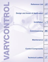
Contents · Innovation<br />
Innovation 2<br />
Functional description 3<br />
Construction · Dimensions 4<br />
Nomenclature 5<br />
Aerodynamic and acoustic quick selection<br />
6<br />
2<br />
Type VFC – The System<br />
<strong>Flow</strong> rate adjustment<br />
manual<br />
<strong>Volume</strong> flow controller type VFC<br />
<strong>Flow</strong> rate adjustment<br />
with potentiometers<br />
Air-regenerated noise 7<br />
Case-radiated noise 8<br />
<strong>Flow</strong> rate adjustment 9<br />
Technical data · Wiring examples 10<br />
Order details 11<br />
<strong>Flow</strong> rate adjustment<br />
with mechanical stops<br />
<strong>TROX</strong> type VFC <strong>Volume</strong> <strong>Flow</strong> <strong>Controller</strong> – the innovative solution<br />
Selection according to nominal size of the duct system<br />
<strong>Flow</strong> rate adjustment without special tools<br />
For low velocity systems<br />
Suitable for constant and variable volume flow systems and for ‡ min/‡ max changeover<br />
Lip seal included<br />
Retrofit of actuator easily possible
<strong>TROX</strong> type VFC volume flow controllers are mechanical<br />
system-powered controllers and were developed for the control<br />
of flow rates in constant and variable volume systems with<br />
low velocities. The controllers are suited for both supply and<br />
extract air use. Each controller has been subjected to an aerodynamic<br />
function test. The required flow rate can be easily set<br />
using a scale.<br />
There are 3 configurations of controllers:<br />
Constant flow rate<br />
Variable flow rate, with potentiometers<br />
Variable flow rate, with mechanical stops<br />
The controller operates without external power supply. A control<br />
damper blade mounted in bearings is adjusted by the aerodynamic<br />
forces such that the preset flow rate is held constant<br />
over the entire differential pressure range. Aerodynamic forces<br />
from air flow create a closing force on the damper blade. Selfinflating<br />
bellows amplify this force, acting simultaneously as an<br />
oscillation damper. This closing force is counteracted by a leaf<br />
spring. The result is that as the pressure differential changes,<br />
the damper blade adjusts to keep a constant flow rate within<br />
close tolerances.<br />
VFC, Constant flow rate<br />
<br />
VFC, Variable flow rate,<br />
actuator with potentiometers<br />
<br />
VFC, Variable flow rate,<br />
actuator with mechanical stops<br />
<br />
<br />
<br />
<br />
<br />
<br />
<br />
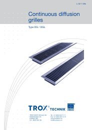
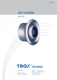
Functional Description<br />
On the internet there is an on-line programme “Air terminal<br />
units” for the design and selection of our units.<br />
Control damper<br />
blade<br />
<strong>Flow</strong> rate scale<br />
<strong>Flow</strong> rate characteristic<br />
curve<br />
Hand wheel<br />
Closing force<br />
Leaf spring<br />
For constant flow rate<br />
<strong>Flow</strong> rate adjustment with hand wheel<br />
For variable flow rates or ‡ min/‡ max changeover<br />
<strong>Flow</strong> rate adjustment with potentiometers<br />
Actuator height 85 mm<br />
For variable flow rates or ‡ min/‡ max changeover<br />
<strong>Flow</strong> rate adjustment with mechanical stops<br />
Compact installation height of actuator 35 mm<br />
Bellows<br />
Actuator,<br />
flow rate adjustment<br />
with potentiometers<br />
Actuator,<br />
flow rate adjustment<br />
with mechanical stops<br />
3
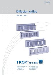
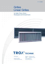
Construction · Dimensions<br />
Characteristics<br />
– Mechanical system-powered, without external power supply<br />
– Suitable for supply or extract air<br />
– <strong>Volume</strong> flow range maximum 10 : 1<br />
– Tolerances on flow rate approx. ± 10 % relative to ‡ nom<br />
– <strong>Flow</strong> rate adjustment using pointer on external scale<br />
– Differential pressure range 30 to 500 Pa<br />
– Correct operation even under unfavourable upstream<br />
and downstream conditions (straight lenght required<br />
upstream 1D)<br />
– Independent of orientation<br />
– The damper blade mechanisms maintenance free<br />
– Operating temperature range 10 to 50 °C<br />
Constructional features<br />
– Circular spigot on both ends with lip seal, suitable for circular<br />
connecting ducts to DIN EN 1506 or DIN EN 13180<br />
– Damper blade shaft supported in bearings<br />
– Casing air leakage complies with DIN EN 1751, class A<br />
– Casing made of galvanized sheet steel<br />
– Stainless steel leaf spring<br />
4<br />
Manual flow rate adjustment<br />
D a<br />
Actuator flow rate adjustment,<br />
V . min and V . max setting with potentiometers<br />
D a<br />
232<br />
232<br />
50<br />
50<br />
– Polyurethane bellows<br />
– Plastic damper blade<br />
Actuators<br />
– For setpoint readjustment or for variable volume flow<br />
– 24 V or 230 VAC power<br />
– Potentiometers or mechanical stops<br />
– Factory fitted, retrofit of actuator easily possible<br />
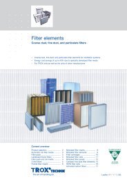
Secondary silencer<br />
– Suitable for VFC<br />
– Rigid circular silencer type CS<br />
– Flexible circular silencer type CF<br />
– See leaflet 6/5/EN/... for dimensions and technical data<br />
Air heater<br />
– Suitable for VFC<br />
– See leaflet 5/20/EN/... for dimensions and technical data<br />
15<br />
Keep clear to provide access for setting<br />
85<br />
Keep clear to provide access to the actuator<br />
approx. 300<br />
approx. 200<br />
approx. 300<br />
approx. 200
Nomenclature<br />
Nomenclature · Construction · Dimensions<br />
fm in Hz: Octave band centre frequency<br />
LW in dB: Sound power level of air-regenerated noise in<br />
the room (low pressure) side ducting<br />
LW2 in dB: Sound power level of case radiated noise<br />
LpA in dB(A): A-weighted sound pressure level of air-regenerated<br />
noise in the room, system attenuation<br />
taken into account<br />
LpA1 in dB(A): A-weighted sound pressure level of air-regenerated<br />
noise in the room with CS050/CF050<br />
circular silencer, system attenuation taken into<br />
account<br />
LpA2 in dB(A): A-weighted sound pressure level of case<br />
radiated noise in the room, system attenuation<br />
taken into account<br />
‡ nom in m3/h or l/s: Nominal flow rate (100 %)<br />
‡ in m3 /h<br />
or l/s: <strong>Flow</strong> rate<br />
Actuator flow rate adjustment,<br />
V . min and V . max setting with mechanical stops<br />
D a<br />
232<br />
50<br />
‡ min unit in m3 /h<br />
or l/s: Minimum unit flow rate<br />
pg in Pa: Total pressure differential<br />
All sound power levels based on 1pW, all sound pressure levels<br />
on 20 µPa.<br />
All noise levels measured in a reverberation chamber.<br />
The sound power data was determined and corrected<br />
according to DIN EN ISO 5135, February 1999.<br />
35<br />
Keep clear to provide access to the actuator<br />
approx. 300<br />
approx. 200<br />
Dimensions in mm Weight in kg<br />
Nominal size<br />
Ø D a<br />
<strong>Flow</strong> rate<br />
constant variable<br />
80 79 0.5 0.8<br />
100 99 0.6 0.9<br />
125 124 0.7 1.0<br />
160 159 0.8 1.1<br />
200 199 1.0 1.3<br />
250 249 1.3 1.6<br />
5
Aerodynamic and Acoustic Quick Selection<br />
6<br />
V .<br />
System attenuation in dB/Oct. acc. to VDI 2081 (values incorporated into the quick selection table)<br />
f m in Hz 63 125 250 500 1000 2000 4000 8000<br />
Duct attenuation 0 0 1 2 3 3 3 3<br />
Room attenuation 5 5 5 5 5 5 5 5<br />
End reflection 10 5 2 0 0 0 0 0<br />
Correction for distribution into the duct system (values incorporated into the quick selection table)<br />
l/s 150 200 250 300 360<br />
m 3 /h 540 720 900 1080 1296<br />
dB per octave 0 2 3 3 4<br />
Nominal<br />
size<br />
Correction for other pressure differentials (averaged values)<br />
∆ p g in Pa 50 100 200 400 500<br />
80<br />
100<br />
125<br />
160<br />
200<br />
250<br />
dB – 6 0 6 12 16<br />
V . 1)<br />
l/s m 3 /h<br />
6 22<br />
10 36<br />
20 72<br />
42 151<br />
6 22<br />
15 54<br />
30 108<br />
65 234<br />
10 36<br />
20 72<br />
45 162<br />
100 360<br />
18 65<br />
45 162<br />
85 306<br />
185 666<br />
25 90<br />
60 216<br />
120 432<br />
250 900<br />
37 133<br />
100 360<br />
185 666<br />
370 1332<br />
Quick selection of sound pressure level in dB(A) with ∆ p g = 100 Pa<br />
without<br />
Air-regenerated noise<br />
with circular silencer type CS050/CF050<br />
circular LpA1 silencer Length in mm<br />
LpA 500 1000 1500<br />
Case-radiated noise 2)<br />
31 17 10 8 13<br />
34 20 12 10 15<br />
39 26 17 16 18<br />
44 31 21 19 23<br />
34 19 9 6 17<br />
38 24 15 13 20<br />
41 29 21 19 22<br />
46 36 29 27 25<br />
27 15 6 4 5<br />
33 21 13 10 10<br />
39 29 22 20 15<br />
46 38 32 30 21<br />
32 22 14 11 20<br />
38 28 22 19 25<br />
42 33 28 25 28<br />
46 38 34 31 33<br />
33 22 14 11 18<br />
38 28 20 18 23<br />
42 32 26 24 28<br />
44 35 30 28 32<br />
37 27 18 15 23<br />
41 32 24 22 28<br />
43 34 26 24 31<br />
44 36 29 27 34<br />
1) The smallest value stated for each nominal size is referred to as V . min unit, the largest value as V . nom.<br />
2) 4 dB/octave ceiling reduction and 5 dB/octave room attenuation have been allowed for in the calculation of case-radiated noise.<br />
L pA2
VFC<br />
L W<br />
<br />
L W2 Case-radiated noise<br />
L pA2 Case-radiated noise<br />
Nominal size<br />
80<br />
100<br />
125<br />
160<br />
200<br />
250<br />
Room<br />
Microphone<br />
V .<br />
l/s m 3 /h<br />
6 22<br />
10 36<br />
20 72<br />
42 151<br />
6 22<br />
15 54<br />
30 108<br />
65 234<br />
10 36<br />
20 72<br />
45 162<br />
100 360<br />
18 65<br />
45 162<br />
85 306<br />
185 666<br />
25 90<br />
60 216<br />
120 432<br />
250 900<br />
37 133<br />
100 360<br />
185 666<br />
370 1332<br />
63<br />
<br />
without<br />
LpA circular silencer<br />
with<br />
LpA1 CS050/CF050<br />
circular silencer<br />
Nomenclature, see page 5<br />
125<br />
Air-regenerated Noise<br />
CS050/CF050 circular silencer<br />
End reflection based on diffuser<br />
Air-regenerated noise<br />
∆ pg = 100 Pa<br />
∆ pg = 200 Pa<br />
250<br />
L W in dB<br />
f m in Hz<br />
500<br />
1000<br />
2000<br />
4000<br />
8000<br />
63<br />
125<br />
250<br />
L W in dB<br />
f m in Hz<br />
500<br />
57 42 39 36 34 28 24 25 58 46 44 42 41 36 35 37 60 52 50 49 50 45 49 53<br />
57 47 44 40 37 31 25 25 59 51 48 46 43 38 36 37 61 56 54 53 52 48 50 53<br />
58 52 50 45 40 34 26 25 59 57 54 51 47 42 37 37 61 62 60 58 56 51 51 53<br />
58 58 56 50 44 38 27 24 60 62 61 56 50 45 38 36 62 68 67 64 59 55 52 52<br />
52 39 39 40 38 32 30 27 53 42 43 44 43 39 38 37 55 46 48 50 51 48 50 51<br />
55 48 46 44 41 35 31 28 56 51 50 48 47 42 39 38 58 55 55 54 54 51 51 52<br />
57 56 51 47 44 38 32 29 58 59 55 52 49 45 40 39 60 63 60 57 56 54 52 53<br />
60 64 56 51 46 41 33 30 61 67 60 55 52 48 41 40 63 71 65 61 59 57 53 54<br />
47 34 32 33 30 24 22 21 49 37 36 38 36 32 32 34 51 42 42 45 44 43 46 50<br />
51 43 40 39 35 30 26 24 53 47 44 44 41 38 36 37 56 52 49 50 50 49 50 54<br />
56 54 48 45 41 36 30 28 58 57 52 50 47 44 41 40 61 62 58 56 56 55 55 57<br />
61 64 57 51 47 42 35 31 63 68 61 56 53 51 45 44 66 73 66 62 62 62 59 61<br />
47 41 38 38 34 30 28 28 49 44 42 43 41 38 37 38 52 48 47 50 50 49 50 52<br />
53 50 46 43 40 35 32 31 55 53 50 48 47 43 41 41 57 57 55 55 56 54 53 54<br />
57 57 51 47 44 38 34 33 59 60 55 52 51 47 43 43 61 64 60 59 60 58 56 56<br />
62 64 58 52 49 43 37 35 64 67 62 57 56 51 47 45 66 71 67 64 65 62 59 59<br />
44 39 37 39 37 32 26 24 47 43 42 44 43 40 35 34 51 48 49 51 52 50 48 48<br />
51 48 44 43 41 38 31 27 53 51 49 48 47 46 41 38 57 56 55 55 56 56 54 52<br />
56 54 49 46 44 43 35 30 58 58 54 51 51 51 45 41 62 63 60 58 60 61 58 55<br />
61 61 54 49 48 48 39 34 64 65 59 55 55 56 49 44 67 70 66 62 63 66 62 58<br />
46 37 39 43 40 36 31 27 48 41 43 47 46 43 40 37 52 45 50 53 55 53 52 52<br />
54 45 45 46 44 42 36 31 56 49 49 50 50 50 45 42 60 53 55 56 58 60 58 56<br />
59 50 48 48 46 46 39 34 61 53 53 52 52 54 48 45 65 58 59 58 60 64 61 59<br />
64 55 53 50 48 51 42 37 67 59 57 55 55 58 52 48 70 64 63 61 63 68 64 63<br />
1000<br />
2000<br />
4000<br />
8000<br />
63<br />
125<br />
250<br />
∆ p g = 500 Pa<br />
L W in dB<br />
f m in Hz<br />
500<br />
1000<br />
2000<br />
4000<br />
8000<br />
7
Case-radiated Noise<br />
Example<br />
Given: ‡ max = 45 l/s or 162 m 3 /h<br />
p g = 200 Pa<br />
Required sound pressure level in the room 35 dB(A)<br />
For further assumptions, see calculation procedure<br />
Calculation procedure<br />
Quick selection: VFC 125<br />
Air-regenerated noise LpA = 39 + 6 = 45 dB(A)<br />
Specification is not met, so circular silencer required<br />
VFC 125 with CF050/125 x 500<br />
Air-regenerated noise LpA1 = 29 + 6 = 35 dB(A)<br />
Case-regenerated noise LpA2 = 15 + 6 = 21 dB(A)<br />
8<br />
Nominal size<br />
80<br />
100<br />
125<br />
160<br />
200<br />
250<br />
V .<br />
l/s m 3 /h<br />
6 22<br />
10 36<br />
20 72<br />
42 151<br />
6 22<br />
15 54<br />
30 108<br />
65 234<br />
10 36<br />
20 72<br />
45 162<br />
100 360<br />
18 65<br />
45 162<br />
85 306<br />
185 666<br />
25 90<br />
60 216<br />
120 432<br />
250 900<br />
37 133<br />
100 360<br />
185 666<br />
370 1332<br />
63<br />
125<br />
Case-radiated noise calculation procedure<br />
fm 63 125 250 500 1000 2000 4000 8000<br />
LW2 (Page 8) 32 27 22 26 25 24 25 28<br />
Ceiling reduction 4 4 4 4 4 4 4 4<br />
Room attenuation 6 6 6 5 5 5 5 5<br />
A-weighting –26 –16 –9 –3 0 1 1 –1<br />
Corrected level –4 1 3 14 16 16 17 18<br />
Result: L pA2 approx. 23 dB(A)<br />
Case-radiated noise<br />
∆ pg = 100 Pa<br />
∆ pg = 200 Pa<br />
250<br />
L W2 in dB<br />
f m in Hz<br />
500<br />
1000<br />
2000<br />
4000<br />
8000<br />
63<br />
125<br />
250<br />
L W2 in dB<br />
f m in Hz<br />
500<br />
20 8 6 14 16 16 12 15 21 12 11 20 23 24 23 27 23 18 17 27 32 33 37 43<br />
20 13 11 18 19 19 13 15 22 17 15 24 25 26 24 27 24 22 21 31 34 36 38 43<br />
21 18 17 23 22 22 14 15 22 23 21 29 29 30 25 27 24 28 27 36 38 39 39 43<br />
21 24 23 28 26 26 15 14 23 28 28 34 32 33 26 26 25 34 34 42 41 43 40 42<br />
17 7 8 19 21 20 18 17 18 10 12 23 26 27 26 27 20 14 17 29 34 36 38 41<br />
20 16 15 23 24 23 19 18 21 19 19 27 30 30 27 28 23 23 24 33 37 39 39 42<br />
22 24 20 26 27 26 20 19 23 27 24 31 32 33 28 29 25 31 29 36 39 42 40 43<br />
25 32 25 30 29 29 21 20 26 35 29 34 35 36 29 30 28 39 34 40 42 45 41 44<br />
21 4 2 9 8 4 6 9 23 7 6 14 14 12 16 22 25 12 12 21 22 23 30 38<br />
25 13 10 15 13 10 10 12 27 17 14 20 19 18 20 25 30 22 19 26 28 29 34 42<br />
30 24 18 21 19 16 14 16 32 27 22 26 25 24 25 28 35 32 28 32 34 35 39 45<br />
35 34 27 27 25 22 19 19 37 38 31 32 31 31 29 32 40 43 36 38 40 42 43 49<br />
22 18 18 20 24 21 19 24 24 21 22 25 31 29 28 34 27 25 27 32 40 40 41 48<br />
28 27 26 25 30 26 23 27 30 30 30 30 37 34 32 37 32 34 35 37 46 45 44 50<br />
32 34 31 29 34 29 25 29 34 37 35 34 41 38 34 39 36 41 40 41 50 49 47 52<br />
37 41 38 34 39 34 28 31 39 44 42 39 46 42 38 41 41 48 47 46 55 53 50 55<br />
23 22 22 24 23 21 17 15 26 26 27 29 29 29 26 25 30 31 34 36 38 39 39 39<br />
30 31 29 28 27 27 22 18 32 34 34 33 33 35 32 29 36 39 40 40 42 45 45 43<br />
35 37 34 31 30 32 26 21 37 41 39 36 37 40 36 32 41 46 45 43 46 50 49 46<br />
40 44 39 34 34 37 30 25 43 48 44 40 41 45 40 35 46 53 51 47 49 55 53 49<br />
27 22 25 29 27 25 22 18 29 26 29 33 33 32 31 28 33 30 36 39 42 42 43 43<br />
35 30 31 32 31 31 27 22 37 34 35 36 37 39 36 33 41 38 41 42 45 49 49 47<br />
40 35 34 34 33 35 30 25 42 38 39 38 39 43 39 36 46 43 45 44 47 53 52 50<br />
45 40 39 36 35 40 33 28 48 44 43 41 42 47 43 39 51 49 49 47 50 57 55 54<br />
1000<br />
2000<br />
4000<br />
8000<br />
63<br />
125<br />
250<br />
∆ p g = 500 Pa<br />
L W2 in dB<br />
f m in Hz<br />
500<br />
1000<br />
2000<br />
4000<br />
8000
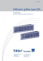
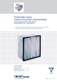
Characteristic curve for determination of flow rate<br />
10<br />
9<br />
8<br />
7<br />
6<br />
5<br />
VFC 160<br />
4<br />
3<br />
18 40 60 80 100 120 140 160 l/s 185<br />
65100<br />
200 300 400 3 500 m /h 600 666<br />
Constant flow rate control, flow rate adjustment with hand wheel<br />
Hand wheeel<br />
Locking screw<br />
<strong>Flow</strong> Rate Adjustment<br />
The required flow rate must be set by the customer using<br />
the hand wheel. For delivery, setting is a value of 5.<br />
Variable flow rate control, flow rate control with actuator, V . min and V . max setting with potentiometers<br />
‡ max potentiometer<br />
‡ min potentiometer<br />
The flow rate range must be set at the actuator ‡ min and ‡ max<br />
potentiometers by the customer. For delivery, settings are<br />
‡ min = 4 and ‡ max = 8.<br />
Variable flow rate control, flow rate control with actuator, V . min and V . max setting with mechanical stops<br />
Mechanical<br />
stop for ‡ min<br />
Mechanical<br />
stop for ‡ max<br />
On each VFC, a flow rate characteristic curve is shown in<br />
order to determine the settings on site (see example nominal<br />
size 160 opposite).<br />
‡ min values of less 3 cause a system pressure-dependent,<br />
uncontrolled flow rate which does not exceed ‡ min unit.<br />
To adjust the flow rate range the mechanical stops of the<br />
actuator are set corresponding to the values determined<br />
from the characteristic curve. For delivery, settings are<br />
‡ min = 4 and ‡ max = 8.<br />
9
Technical Data · Wiring Examples<br />
10<br />
Variable flow rate control, flow rate control with actuator,<br />
V . min and V . max adjustment with potentiometers<br />
Actuator 24 V, V .<br />
Indicator light Potentiometer<br />
Example: Variable flow rate control<br />
24 V<br />
Variable flow rate control, flow rate control with actuator,<br />
V . min and V . max adjustment with mechanical stops<br />
Mechanical stops<br />
Room temperature<br />
controller<br />
y<br />
1 2 3<br />
VFC<br />
Example: V . min/V . max changeover,<br />
single-wire-control<br />
N L<br />
1 2 3<br />
Switch position: ‡ max<br />
VFC<br />
Service button<br />
min/V .<br />
max changeover<br />
Supply voltage : 24 VAC ± 20 %, 50/60 Hz<br />
or 24 VDC ± 10 %<br />
Power rating : max. 3 VA (for a.c. voltage)<br />
max. 3 W (for d.c. voltage)<br />
Control signal : 1- or 2-wire control<br />
Protection level: IP 42<br />
Actuator 24 V, variable flow rate<br />
Supply voltage and power rating as above.<br />
Control signal : 0 to 10 VDC, Ri > 100 kΩ<br />
Protection level: IP 42<br />
Actuator 230 VAC, V .<br />
min/V .<br />
max changeover<br />
Supply voltage : 230 VAC ± 20 %, 50/60 Hz<br />
Power rating : 3 VA<br />
Control signal : 1- or 2-wire control<br />
Protection level: IP 42<br />
Functional testing<br />
– Press service button<br />
– Actuator turns towards ‡ min<br />
– Actuator turns towards ‡ max<br />
– Actuator returns to control mode<br />
Indicator light provides functional information<br />
– permanently on : Position set<br />
– blinking once a second : Actuator operating<br />
– blinking twice a second: Actuator is stationary<br />
– off : No supply voltage<br />
Actuator 24 V, V .<br />
max changeover<br />
Supply voltage : 24 VAC ± 20 %, 50/60 Hz<br />
or 24 VDC ± 20 %<br />
Power rating : max. 1 VA (for a.c. voltage)<br />
max. 0.5 W (for d.c. voltage)<br />
Protection level: IP 54<br />
Actuator 230 VAC, V .<br />
min/V .<br />
max changeover<br />
Supply voltage : 110 ... 230 VAC ± 20 %, 50/60 Hz<br />
Power rating : 3 VA<br />
Control signal : 1- or 2-wire control<br />
Protection level: IP 54<br />
min/V .
Specification text*<br />
Circular volume flow controllers for constant or variable<br />
volume flow low velocity systems, mechanical systempowered<br />
(external power supply not required), for supply<br />
or extract air, in 6 nominal sizes. Consists of casing with a<br />
control damper blade shaft mounted, supported on bearings<br />
with a bellows, leaf spring and adjustment mechanism.<br />
Special features:<br />
– For constant or variable volume flow systems<br />
– <strong>Flow</strong> rate adjustment without special tools<br />
– Independent of orientation and maintenance free<br />
– Retrofit of actuator easily possible<br />
Spigots suitable for ducts complying with DIN EN 1506 or<br />
DIN EN 13180, with lip seal.<br />
Differential pressure range 30 to 500 Pa, flow rate range<br />
maximum 10 : 1.<br />
Order code<br />
Type<br />
<strong>Volume</strong> flow controller VFC<br />
Order example<br />
Make: <strong>TROX</strong><br />
Type: VFC / 100<br />
VFC / 100 /<br />
80<br />
100<br />
125<br />
160<br />
200<br />
250<br />
Nom. size<br />
Order Details<br />
Materials:<br />
Casing in galvanized sheet steel, control damper blade and<br />
other components in plastic, polyurethane bellows.<br />
* Text for basic construction<br />
Control function<br />
Basic construction (manual setting), no entry required<br />
E01 24 V, ‡ min/‡ max changeover, with potentiometers<br />
E02 230 VAC, ‡ min/‡ max changeover, with potentiometers<br />
E03 24 V, variable volume flow, with potentiometers,<br />
control signal 0 to 10 VDC<br />
M01 24 V, ‡ min/‡ max changeover, with mechanical stops<br />
M02 230 VAC, ‡ min/‡ max changeover, with mechanical stops<br />
11<br />
Design changes reserved · All rights reserved © <strong>TROX</strong> GmbH (04/2008)